

Page 1

Miranda Router Configurator v3.7.0
User’s Guide
UG0051-02
www.miranda.com
Page 2

Copyright & Trademark Notice
Copyright © 2014 Grass Valley. All rights reserved.
Belden, Belden Sending All The Right Signals, and the Belden logo are trademarks or
registered trademarks of Belden Inc. or its affiliated companies in the United States and
other jurisdictions. Grass Valley, NVISION, and Miranda Router Configurator are trademarks or
registered trademarks of Grass Valley. Belden Inc., Grass Valley, and other parties may also
have trademark rights in other terms used herein.
Terms and Conditions
Please read the following terms and conditions carefully. By using Miranda Router
Configurator documentation, you agree to the following terms and conditions.
Gr ass Valley he reby grant s pe rmi ssi on and licen se t o owners of M ira nda Rou ter Conf igu rator
routers to use their product manuals for their own internal business use. Manuals for Grass
Valley products may not be reproduced or transmitted in any form or by any means,
electronic or mechanical, including photocopying and recording, for any purpose unless
specifically authorized in writing by Grass Valley.
A Grass Valley manual may have been revised to reflect changes made to the product during
its manufacturing life. Thus, different versions of a manual may exist for any given product.
Care should be taken to ensure that one obtains the proper manual version for a specific
product serial number.
Information in this document is subject to change without notice and does not represent a
commitment on the part of Grass Valley.
Warranty information is available in the support section of the Grass Valley web site
(www.grassvalley.com).
Title MRC User’s Guide
Part Number UG0051-02
Revision 1.2 (11 Nov 14)
ii
Page 3
Miranda Router Configurator
User’s Guide
Change History
Rev Date ECO Description of Changes Approved By
1.0 24 Apr 13 18826 Initial release with MRC v3.3.1 D.Cox
1.1 03 Fe b 14 19133 Conforms to MRC v3.5.0 and v3.5.2 hybrid firmware.
Added material for pass-through and stereo audio,
for frame sync cards, and for Sony’s ROT-16 protocol.
1.2 11 Nov 14 19356 Conforms to MRC v3.7.0 D.Cox
D.Cox
FCC Statement
This equipment has been tested and found to comply with the limits for a Class A digital
device, pursuant to part 15 of the FCC Rules. These limits are designed to provide reasonable
protection against harmful interference when the equipment is operated in a commercial
environment. This equipment generates, uses, and can radiate radio frequency energy and,
if not installed and used in accordance with the instruction manual, may cause harmful
interference to radio communications. Operation of this equipment in a residential area is
likely to cause harmful interference in which case the user will be required to correct the
interference at his own expense.
Declaration of Conformance (CE)
All of the equipment described in this manual has been designed to conform with the
required safety and emissions standards of the European Community. Products tested and
verified to meet these standards are marked as required by law with the CE mark.
When shipped into member countries of the European Community, this equipment is
accompanied by authentic copies of original Declarations of Conformance on file in the
Grass Valley offices in Grass Valley, California USA.
Software License Agreement and Warranty Information
Contact Grass Valley for details on the software license agreement and product warranty.
iii
Page 4

iv
Page 5

Table of Contents
1 Getting Started. . . . . . . . . . . . . . . . . . . . . . . . . . . . . . . . . . . . . . . . . 1
PC Requirements. . . . . . . . . . . . . . . . . . . . . . . . . . . . . . . . . . . . . . . . . . . . . . . . . . . . . . . . . . . . . . . . . . . . . . . . . . . . . . . . 2
Assigning IP Address to PC . . . . . . . . . . . . . . . . . . . . . . . . . . . . . . . . . . . . . . . . . . . . . . . . . . . . . . . . . . . . . . . . . . . . . . 2
Installing MRC . . . . . . . . . . . . . . . . . . . . . . . . . . . . . . . . . . . . . . . . . . . . . . . . . . . . . . . . . . . . . . . . . . . . . . . . . . . . . . . . . . 6
Verifying Your Installation . . . . . . . . . . . . . . . . . . . . . . . . . . . . . . . . . . . . . . . . . . . . . . . . . . . . . . . . . . . . . . . . . . 9
2 Using MRC . . . . . . . . . . . . . . . . . . . . . . . . . . . . . . . . . . . . . . . . . . . . 11
Overview of MRC. . . . . . . . . . . . . . . . . . . . . . . . . . . . . . . . . . . . . . . . . . . . . . . . . . . . . . . . . . . . . . . . . . . . . . . . . . . . . . . 11
MRC Tools . . . . . . . . . . . . . . . . . . . . . . . . . . . . . . . . . . . . . . . . . . . . . . . . . . . . . . . . . . . . . . . . . . . . . . . . . . . . . . . . 13
Network Setup . . . . . . . . . . . . . . . . . . . . . . . . . . . . . . . . . . . . . . . . . . . . . . . . . . . . . . . . . . . . . . . . . . . . . . . 14
Configuration . . . . . . . . . . . . . . . . . . . . . . . . . . . . . . . . . . . . . . . . . . . . . . . . . . . . . . . . . . . . . . . . . . . . . . . . 14
Router Tools. . . . . . . . . . . . . . . . . . . . . . . . . . . . . . . . . . . . . . . . . . . . . . . . . . . . . . . . . . . . . . . . . . . . . . . . . . 15
Configurator Tools . . . . . . . . . . . . . . . . . . . . . . . . . . . . . . . . . . . . . . . . . . . . . . . . . . . . . . . . . . . . . . . . . . . 15
Selecting a Control Card. . . . . . . . . . . . . . . . . . . . . . . . . . . . . . . . . . . . . . . . . . . . . . . . . . . . . . . . . . . . . . . . . . . . . . . . 15
Control Card State Indicators . . . . . . . . . . . . . . . . . . . . . . . . . . . . . . . . . . . . . . . . . . . . . . . . . . . . . . . . . . . . . . 16
Refreshing the Control Card Display . . . . . . . . . . . . . . . . . . . . . . . . . . . . . . . . . . . . . . . . . . . . . . . . . . . . . . . 17
Saving Configuration Changes . . . . . . . . . . . . . . . . . . . . . . . . . . . . . . . . . . . . . . . . . . . . . . . . . . . . . . . . . . . . . . . . . 17
The MRC Interface. . . . . . . . . . . . . . . . . . . . . . . . . . . . . . . . . . . . . . . . . . . . . . . . . . . . . . . . . . . . . . . . . . . . . . . . . . . . . . 18
Using Tabbed Tables . . . . . . . . . . . . . . . . . . . . . . . . . . . . . . . . . . . . . . . . . . . . . . . . . . . . . . . . . . . . . . . . . . . . . . 18
Table Commands. . . . . . . . . . . . . . . . . . . . . . . . . . . . . . . . . . . . . . . . . . . . . . . . . . . . . . . . . . . . . . . . . . . . . 20
Keyboard Commands . . . . . . . . . . . . . . . . . . . . . . . . . . . . . . . . . . . . . . . . . . . . . . . . . . . . . . . . . . . . . . . . . . . . . 22
Icons. . . . . . . . . . . . . . . . . . . . . . . . . . . . . . . . . . . . . . . . . . . . . . . . . . . . . . . . . . . . . . . . . . . . . . . . . . . . . . . . . . . . . . 22
Setting Preferences . . . . . . . . . . . . . . . . . . . . . . . . . . . . . . . . . . . . . . . . . . . . . . . . . . . . . . . . . . . . . . . . . . . . . . . . . . . . 23
Screen Size . . . . . . . . . . . . . . . . . . . . . . . . . . . . . . . . . . . . . . . . . . . . . . . . . . . . . . . . . . . . . . . . . . . . . . . . . . . . . . . 23
Other Topics . . . . . . . . . . . . . . . . . . . . . . . . . . . . . . . . . . . . . . . . . . . . . . . . . . . . . . . . . . . . . . . . . . . . . . . . . . . . . . . . . . . 23
Context Menu . . . . . . . . . . . . . . . . . . . . . . . . . . . . . . . . . . . . . . . . . . . . . . . . . . . . . . . . . . . . . . . . . . . . . . . . . . . . 23
Nomenclature . . . . . . . . . . . . . . . . . . . . . . . . . . . . . . . . . . . . . . . . . . . . . . . . . . . . . . . . . . . . . . . . . . . . . . . . . . . . 25
3 Configuring Routers . . . . . . . . . . . . . . . . . . . . . . . . . . . . . . . . . . . 27
Firmware Page . . . . . . . . . . . . . . . . . . . . . . . . . . . . . . . . . . . . . . . . . . . . . . . . . . . . . . . . . . . . . . . . . . . . . . . . . . . . . . . . 28
Using the Firmware Page . . . . . . . . . . . . . . . . . . . . . . . . . . . . . . . . . . . . . . . . . . . . . . . . . . . . . . . . . . . . . . . . . . 29
Choosing a Firmware file . . . . . . . . . . . . . . . . . . . . . . . . . . . . . . . . . . . . . . . . . . . . . . . . . . . . . . . . . . . . . . . . . . 30
‘Used on This Control Card’ Option. . . . . . . . . . . . . . . . . . . . . . . . . . . . . . . . . . . . . . . . . . . . . . . . . . . . 30
‘All Available’ Option . . . . . . . . . . . . . . . . . . . . . . . . . . . . . . . . . . . . . . . . . . . . . . . . . . . . . . . . . . . . . . . . . 31
The ‘Available’ Column . . . . . . . . . . . . . . . . . . . . . . . . . . . . . . . . . . . . . . . . . . . . . . . . . . . . . . . . . . . . . . . 31
Context Menu . . . . . . . . . . . . . . . . . . . . . . . . . . . . . . . . . . . . . . . . . . . . . . . . . . . . . . . . . . . . . . . . . . . . . . . . 32
Updating Firmware. . . . . . . . . . . . . . . . . . . . . . . . . . . . . . . . . . . . . . . . . . . . . . . . . . . . . . . . . . . . . . . . . . . . . . . . 32
Creating a Module Selection Rule . . . . . . . . . . . . . . . . . . . . . . . . . . . . . . . . . . . . . . . . . . . . . . . . . . . . . 32
Viewing and Saving Update Logs . . . . . . . . . . . . . . . . . . . . . . . . . . . . . . . . . . . . . . . . . . . . . . . . . . . . . . . . . . 37
Router Levels Page . . . . . . . . . . . . . . . . . . . . . . . . . . . . . . . . . . . . . . . . . . . . . . . . . . . . . . . . . . . . . . . . . . . . . . . . . . . . 37
Using the Router Levels Page . . . . . . . . . . . . . . . . . . . . . . . . . . . . . . . . . . . . . . . . . . . . . . . . . . . . . . . . . . . . . . 38
Network Frame Summary . . . . . . . . . . . . . . . . . . . . . . . . . . . . . . . . . . . . . . . . . . . . . . . . . . . . . . . . . . . . . . . . . 39
Physical Levels . . . . . . . . . . . . . . . . . . . . . . . . . . . . . . . . . . . . . . . . . . . . . . . . . . . . . . . . . . . . . . . . . . . . . . . . . . . . 39
Level Types . . . . . . . . . . . . . . . . . . . . . . . . . . . . . . . . . . . . . . . . . . . . . . . . . . . . . . . . . . . . . . . . . . . . . . . . . . 40
Special Case for NV8500 Hybrid Routers. . . . . . . . . . . . . . . . . . . . . . . . . . . . . . . . . . . . . . . . . . . . . . . 41
v
Page 6

Table of Contents
Adding and Updating Levels . . . . . . . . . . . . . . . . . . . . . . . . . . . . . . . . . . . . . . . . . . . . . . . . . . . . . . . . . . 41
Deleting Levels. . . . . . . . . . . . . . . . . . . . . . . . . . . . . . . . . . . . . . . . . . . . . . . . . . . . . . . . . . . . . . . . . . . . . . . 42
Special Audio Sources . . . . . . . . . . . . . . . . . . . . . . . . . . . . . . . . . . . . . . . . . . . . . . . . . . . . . . . . . . . . . . . . . . . . . 43
Regions of the Special Audio Section. . . . . . . . . . . . . . . . . . . . . . . . . . . . . . . . . . . . . . . . . . . . . . . . . . 44
Null Audio Source . . . . . . . . . . . . . . . . . . . . . . . . . . . . . . . . . . . . . . . . . . . . . . . . . . . . . . . . . . . . . . . . . . . . 44
Pass-Through Audio Sources. . . . . . . . . . . . . . . . . . . . . . . . . . . . . . . . . . . . . . . . . . . . . . . . . . . . . . . . . . 45
Input Attributes Page . . . . . . . . . . . . . . . . . . . . . . . . . . . . . . . . . . . . . . . . . . . . . . . . . . . . . . . . . . . . . . . . . . . . . . . . . . 48
Card Selection . . . . . . . . . . . . . . . . . . . . . . . . . . . . . . . . . . . . . . . . . . . . . . . . . . . . . . . . . . . . . . . . . . . . . . . . . . . . 49
Caveats . . . . . . . . . . . . . . . . . . . . . . . . . . . . . . . . . . . . . . . . . . . . . . . . . . . . . . . . . . . . . . . . . . . . . . . . . . . . . . . . . . . 49
Nomenclature . . . . . . . . . . . . . . . . . . . . . . . . . . . . . . . . . . . . . . . . . . . . . . . . . . . . . . . . . . . . . . . . . . . . . . . . . . . . 50
Context Menu. . . . . . . . . . . . . . . . . . . . . . . . . . . . . . . . . . . . . . . . . . . . . . . . . . . . . . . . . . . . . . . . . . . . . . . . . . . . . 50
Output Attributes Page . . . . . . . . . . . . . . . . . . . . . . . . . . . . . . . . . . . . . . . . . . . . . . . . . . . . . . . . . . . . . . . . . . . . . . . . 50
Using the Output Attributes Page . . . . . . . . . . . . . . . . . . . . . . . . . . . . . . . . . . . . . . . . . . . . . . . . . . . . . . . . . 51
AES Reference Options . . . . . . . . . . . . . . . . . . . . . . . . . . . . . . . . . . . . . . . . . . . . . . . . . . . . . . . . . . . . . . . 52
Dual Video Reference Options . . . . . . . . . . . . . . . . . . . . . . . . . . . . . . . . . . . . . . . . . . . . . . . . . . . . . . . . 52
Output Range . . . . . . . . . . . . . . . . . . . . . . . . . . . . . . . . . . . . . . . . . . . . . . . . . . . . . . . . . . . . . . . . . . . . . . . . 53
The Attributes Table . . . . . . . . . . . . . . . . . . . . . . . . . . . . . . . . . . . . . . . . . . . . . . . . . . . . . . . . . . . . . . . . . . 53
Output Attributes Context Menu. . . . . . . . . . . . . . . . . . . . . . . . . . . . . . . . . . . . . . . . . . . . . . . . . . . . . . 54
Configuring and Updating Output Attributes . . . . . . . . . . . . . . . . . . . . . . . . . . . . . . . . . . . . . . . . . . . . . . 55
Redundant Crosspoint Page . . . . . . . . . . . . . . . . . . . . . . . . . . . . . . . . . . . . . . . . . . . . . . . . . . . . . . . . . . . . . . . . . . . . 56
Manual Redundant Switchover . . . . . . . . . . . . . . . . . . . . . . . . . . . . . . . . . . . . . . . . . . . . . . . . . . . . . . . . . . . . 59
NV8140 Switchover. . . . . . . . . . . . . . . . . . . . . . . . . . . . . . . . . . . . . . . . . . . . . . . . . . . . . . . . . . . . . . . . . . . 59
NV8144 Switchover. . . . . . . . . . . . . . . . . . . . . . . . . . . . . . . . . . . . . . . . . . . . . . . . . . . . . . . . . . . . . . . . . . . 60
NV8280 Switchover. . . . . . . . . . . . . . . . . . . . . . . . . . . . . . . . . . . . . . . . . . . . . . . . . . . . . . . . . . . . . . . . . . . 61
NV8576 and NV8576-Plus Switchover . . . . . . . . . . . . . . . . . . . . . . . . . . . . . . . . . . . . . . . . . . . . . . . . . 63
Miscellaneous Page . . . . . . . . . . . . . . . . . . . . . . . . . . . . . . . . . . . . . . . . . . . . . . . . . . . . . . . . . . . . . . . . . . . . . . . . . . . . 65
Serial Port Settings . . . . . . . . . . . . . . . . . . . . . . . . . . . . . . . . . . . . . . . . . . . . . . . . . . . . . . . . . . . . . . . . . . . . . . . . 66
Viewing Serial Port Settings. . . . . . . . . . . . . . . . . . . . . . . . . . . . . . . . . . . . . . . . . . . . . . . . . . . . . . . . . . . 66
Router Serial Settings . . . . . . . . . . . . . . . . . . . . . . . . . . . . . . . . . . . . . . . . . . . . . . . . . . . . . . . . . . . . . . . . . 67
Control Card Settings. . . . . . . . . . . . . . . . . . . . . . . . . . . . . . . . . . . . . . . . . . . . . . . . . . . . . . . . . . . . . . . . . . . . . . 67
Ethernet Protocol Settings. . . . . . . . . . . . . . . . . . . . . . . . . . . . . . . . . . . . . . . . . . . . . . . . . . . . . . . . . . . . . . . . . 68
Configuring Serial Ports . . . . . . . . . . . . . . . . . . . . . . . . . . . . . . . . . . . . . . . . . . . . . . . . . . . . . . . . . . . . . . . . . . . 69
How to Configure Serial Ports . . . . . . . . . . . . . . . . . . . . . . . . . . . . . . . . . . . . . . . . . . . . . . . . . . . . . . . . . 69
Expansion Settings . . . . . . . . . . . . . . . . . . . . . . . . . . . . . . . . . . . . . . . . . . . . . . . . . . . . . . . . . . . . . . . . . . . . . . . . 69
How to Set a Frame as Main or Expansion . . . . . . . . . . . . . . . . . . . . . . . . . . . . . . . . . . . . . . . . . . . . . 70
Module Types . . . . . . . . . . . . . . . . . . . . . . . . . . . . . . . . . . . . . . . . . . . . . . . . . . . . . . . . . . . . . . . . . . . . . . . . . . . . . . . . . 71
Selecting Slots . . . . . . . . . . . . . . . . . . . . . . . . . . . . . . . . . . . . . . . . . . . . . . . . . . . . . . . . . . . . . . . . . . . . . . . . . . . . 73
Context Menus. . . . . . . . . . . . . . . . . . . . . . . . . . . . . . . . . . . . . . . . . . . . . . . . . . . . . . . . . . . . . . . . . . . . . . . . . . . . 73
Hybrid Routers Table . . . . . . . . . . . . . . . . . . . . . . . . . . . . . . . . . . . . . . . . . . . . . . . . . . . . . . . . . . . . . . . . . 73
Module Type Table . . . . . . . . . . . . . . . . . . . . . . . . . . . . . . . . . . . . . . . . . . . . . . . . . . . . . . . . . . . . . . . . . . . 74
Setting the Card Type. . . . . . . . . . . . . . . . . . . . . . . . . . . . . . . . . . . . . . . . . . . . . . . . . . . . . . . . . . . . . . . . . 74
Resetting Card Types after a Firmware Update. . . . . . . . . . . . . . . . . . . . . . . . . . . . . . . . . . . . . . . . . 75
Using the Module Types Page . . . . . . . . . . . . . . . . . . . . . . . . . . . . . . . . . . . . . . . . . . . . . . . . . . . . . . . . . . . . . 75
Viewing a Subset of the Modules. . . . . . . . . . . . . . . . . . . . . . . . . . . . . . . . . . . . . . . . . . . . . . . . . . . . . . 75
Assigning Module Types. . . . . . . . . . . . . . . . . . . . . . . . . . . . . . . . . . . . . . . . . . . . . . . . . . . . . . . . . . . . . . . . . . . 75
Troubleshooting Module Type Errors . . . . . . . . . . . . . . . . . . . . . . . . . . . . . . . . . . . . . . . . . . . . . . . . . . . . . . 76
Copy Settings Page . . . . . . . . . . . . . . . . . . . . . . . . . . . . . . . . . . . . . . . . . . . . . . . . . . . . . . . . . . . . . . . . . . . . . . . . . . . . 78
vi
Page 7

Miranda Router Configurator
4 Router Tools . . . . . . . . . . . . . . . . . . . . . . . . . . . . . . . . . . . . . . . . . . 83
Crosspoints Page . . . . . . . . . . . . . . . . . . . . . . . . . . . . . . . . . . . . . . . . . . . . . . . . . . . . . . . . . . . . . . . . . . . . . . . . . . . . . . 84
Diagnostic Levels. . . . . . . . . . . . . . . . . . . . . . . . . . . . . . . . . . . . . . . . . . . . . . . . . . . . . . . . . . . . . . . . . . . . . . . . . . 85
Context Menus. . . . . . . . . . . . . . . . . . . . . . . . . . . . . . . . . . . . . . . . . . . . . . . . . . . . . . . . . . . . . . . . . . . . . . . . . . . . 85
“Live” Changes . . . . . . . . . . . . . . . . . . . . . . . . . . . . . . . . . . . . . . . . . . . . . . . . . . . . . . . . . . . . . . . . . . . . . . . . . . . . 86
Salvos. . . . . . . . . . . . . . . . . . . . . . . . . . . . . . . . . . . . . . . . . . . . . . . . . . . . . . . . . . . . . . . . . . . . . . . . . . . . . . . . . . . . . 86
Locks and Protects . . . . . . . . . . . . . . . . . . . . . . . . . . . . . . . . . . . . . . . . . . . . . . . . . . . . . . . . . . . . . . . . . . . . . . . . 86
Takes . . . . . . . . . . . . . . . . . . . . . . . . . . . . . . . . . . . . . . . . . . . . . . . . . . . . . . . . . . . . . . . . . . . . . . . . . . . . . . . . . . . . . 87
Takes for Non-Existent Ports (for NV8500 Series Routers). . . . . . . . . . . . . . . . . . . . . . . . . . . . . . . 87
Takes for Ports Belonging to Empty Slots . . . . . . . . . . . . . . . . . . . . . . . . . . . . . . . . . . . . . . . . . . . . . . 87
Caveats . . . . . . . . . . . . . . . . . . . . . . . . . . . . . . . . . . . . . . . . . . . . . . . . . . . . . . . . . . . . . . . . . . . . . . . . . . . . . . 89
Using the Crosspoints Page. . . . . . . . . . . . . . . . . . . . . . . . . . . . . . . . . . . . . . . . . . . . . . . . . . . . . . . . . . . . . . . . 90
Icons and Context Menu Options . . . . . . . . . . . . . . . . . . . . . . . . . . . . . . . . . . . . . . . . . . . . . . . . . . . . . 91
Locating Outputs. . . . . . . . . . . . . . . . . . . . . . . . . . . . . . . . . . . . . . . . . . . . . . . . . . . . . . . . . . . . . . . . . . . . . 92
Selecting a Level . . . . . . . . . . . . . . . . . . . . . . . . . . . . . . . . . . . . . . . . . . . . . . . . . . . . . . . . . . . . . . . . . . . . . 93
Viewing a Crosspoint Matrix . . . . . . . . . . . . . . . . . . . . . . . . . . . . . . . . . . . . . . . . . . . . . . . . . . . . . . . . . . . . . . . 94
Performing Takes . . . . . . . . . . . . . . . . . . . . . . . . . . . . . . . . . . . . . . . . . . . . . . . . . . . . . . . . . . . . . . . . . . . . . . . . . 95
Single Input to Single Output . . . . . . . . . . . . . . . . . . . . . . . . . . . . . . . . . . . . . . . . . . . . . . . . . . . . . . . . . 95
Range Takes . . . . . . . . . . . . . . . . . . . . . . . . . . . . . . . . . . . . . . . . . . . . . . . . . . . . . . . . . . . . . . . . . . . . . . . . . 96
Diagonal Takes . . . . . . . . . . . . . . . . . . . . . . . . . . . . . . . . . . . . . . . . . . . . . . . . . . . . . . . . . . . . . . . . . . . . . . . 98
Incrementing Takes Tab . . . . . . . . . . . . . . . . . . . . . . . . . . . . . . . . . . . . . . . . . . . . . . . . . . . . . . . . . . . . . . . . . . 100
How to Perform Incremental Takes. . . . . . . . . . . . . . . . . . . . . . . . . . . . . . . . . . . . . . . . . . . . . . . . . . . 101
History Tab. . . . . . . . . . . . . . . . . . . . . . . . . . . . . . . . . . . . . . . . . . . . . . . . . . . . . . . . . . . . . . . . . . . . . . . . . . . . . . . 102
The History Tools . . . . . . . . . . . . . . . . . . . . . . . . . . . . . . . . . . . . . . . . . . . . . . . . . . . . . . . . . . . . . . . . . . . . 104
Single Takes Tab . . . . . . . . . . . . . . . . . . . . . . . . . . . . . . . . . . . . . . . . . . . . . . . . . . . . . . . . . . . . . . . . . . . . . . . . . 104
How to Perform Single Takes. . . . . . . . . . . . . . . . . . . . . . . . . . . . . . . . . . . . . . . . . . . . . . . . . . . . . . . . . 105
How to Perform Chop Takes . . . . . . . . . . . . . . . . . . . . . . . . . . . . . . . . . . . . . . . . . . . . . . . . . . . . . . . . . 106
Copying and Pasting Crosspoint Data . . . . . . . . . . . . . . . . . . . . . . . . . . . . . . . . . . . . . . . . . . . . . . . . . . . . . 106
Copy . . . . . . . . . . . . . . . . . . . . . . . . . . . . . . . . . . . . . . . . . . . . . . . . . . . . . . . . . . . . . . . . . . . . . . . . . . . . . . . . 106
Paste. . . . . . . . . . . . . . . . . . . . . . . . . . . . . . . . . . . . . . . . . . . . . . . . . . . . . . . . . . . . . . . . . . . . . . . . . . . . . . . . 106
Using Salvos . . . . . . . . . . . . . . . . . . . . . . . . . . . . . . . . . . . . . . . . . . . . . . . . . . . . . . . . . . . . . . . . . . . . . . . . . . . . . 109
Creating and Updating a Salvo . . . . . . . . . . . . . . . . . . . . . . . . . . . . . . . . . . . . . . . . . . . . . . . . . . . . . . 111
Opening a Salvo and Uploading its Crosspoint Data . . . . . . . . . . . . . . . . . . . . . . . . . . . . . . . . . . 112
Deleting a Salvo. . . . . . . . . . . . . . . . . . . . . . . . . . . . . . . . . . . . . . . . . . . . . . . . . . . . . . . . . . . . . . . . . . . . . . . . . . 113
Logs Page . . . . . . . . . . . . . . . . . . . . . . . . . . . . . . . . . . . . . . . . . . . . . . . . . . . . . . . . . . . . . . . . . . . . . . . . . . . . . . . . . . . . 114
System Status . . . . . . . . . . . . . . . . . . . . . . . . . . . . . . . . . . . . . . . . . . . . . . . . . . . . . . . . . . . . . . . . . . . . . . . . . . . . . . . . 115
Status Panels. . . . . . . . . . . . . . . . . . . . . . . . . . . . . . . . . . . . . . . . . . . . . . . . . . . . . . . . . . . . . . . . . . . . . . . . . . . . . 116
Module Status Page . . . . . . . . . . . . . . . . . . . . . . . . . . . . . . . . . . . . . . . . . . . . . . . . . . . . . . . . . . . . . . . . . . . . . . . . . . 117
Network Frame Summary . . . . . . . . . . . . . . . . . . . . . . . . . . . . . . . . . . . . . . . . . . . . . . . . . . . . . . . . . . . . . . . . 118
List of Modules. . . . . . . . . . . . . . . . . . . . . . . . . . . . . . . . . . . . . . . . . . . . . . . . . . . . . . . . . . . . . . . . . . . . . . . . . . . 118
Individual Module State . . . . . . . . . . . . . . . . . . . . . . . . . . . . . . . . . . . . . . . . . . . . . . . . . . . . . . . . . . . . . . . . . . 120
Graphic . . . . . . . . . . . . . . . . . . . . . . . . . . . . . . . . . . . . . . . . . . . . . . . . . . . . . . . . . . . . . . . . . . . . . . . . . . . . . . . . . . 122
Selecting Modules. . . . . . . . . . . . . . . . . . . . . . . . . . . . . . . . . . . . . . . . . . . . . . . . . . . . . . . . . . . . . . . . . . . . . . . . 123
Using the Module Status Page . . . . . . . . . . . . . . . . . . . . . . . . . . . . . . . . . . . . . . . . . . . . . . . . . . . . . . . . . . . . 123
Troubleshooting Module Status Errors . . . . . . . . . . . . . . . . . . . . . . . . . . . . . . . . . . . . . . . . . . . . . . . . . . . . 123
View Change Report. . . . . . . . . . . . . . . . . . . . . . . . . . . . . . . . . . . . . . . . . . . . . . . . . . . . . . . . . . . . . . . . . 123
View Status Report . . . . . . . . . . . . . . . . . . . . . . . . . . . . . . . . . . . . . . . . . . . . . . . . . . . . . . . . . . . . . . . . . . 125
User’s Guide
vii
Page 8

Table of Contents
5 Network Setup . . . . . . . . . . . . . . . . . . . . . . . . . . . . . . . . . . . . . . . 127
NVISION Series Products Page . . . . . . . . . . . . . . . . . . . . . . . . . . . . . . . . . . . . . . . . . . . . . . . . . . . . . . . . . . . . . . . . . 128
Network Interfaces Button. . . . . . . . . . . . . . . . . . . . . . . . . . . . . . . . . . . . . . . . . . . . . . . . . . . . . . . . . . . . . . . . 129
Ethernet Settings Page . . . . . . . . . . . . . . . . . . . . . . . . . . . . . . . . . . . . . . . . . . . . . . . . . . . . . . . . . . . . . . . . . . . . . . . 129
Frame Sync Cards . . . . . . . . . . . . . . . . . . . . . . . . . . . . . . . . . . . . . . . . . . . . . . . . . . . . . . . . . . . . . . . . . . . . . . . . 130
Using the Page . . . . . . . . . . . . . . . . . . . . . . . . . . . . . . . . . . . . . . . . . . . . . . . . . . . . . . . . . . . . . . . . . . . . . . . . . . . 130
Entries for Control Cards . . . . . . . . . . . . . . . . . . . . . . . . . . . . . . . . . . . . . . . . . . . . . . . . . . . . . . . . . . . . . 131
Entries for Frame Sync Cards . . . . . . . . . . . . . . . . . . . . . . . . . . . . . . . . . . . . . . . . . . . . . . . . . . . . . . . . . 132
Adding and Removing Control Cards . . . . . . . . . . . . . . . . . . . . . . . . . . . . . . . . . . . . . . . . . . . . . . . . . . . . . 132
Adding Control Cards. . . . . . . . . . . . . . . . . . . . . . . . . . . . . . . . . . . . . . . . . . . . . . . . . . . . . . . . . . . . . . . . 132
Removing Control Cards . . . . . . . . . . . . . . . . . . . . . . . . . . . . . . . . . . . . . . . . . . . . . . . . . . . . . . . . . . . . . 132
Creating Virtual Control Cards . . . . . . . . . . . . . . . . . . . . . . . . . . . . . . . . . . . . . . . . . . . . . . . . . . . . . . . . . . . . 133
Locking and Unlocking Configurations . . . . . . . . . . . . . . . . . . . . . . . . . . . . . . . . . . . . . . . . . . . . . . . . . . . 136
Updating an IP Address. . . . . . . . . . . . . . . . . . . . . . . . . . . . . . . . . . . . . . . . . . . . . . . . . . . . . . . . . . . . . . . . . . . 137
6 Tutorials . . . . . . . . . . . . . . . . . . . . . . . . . . . . . . . . . . . . . . . . . . . . . 139
The MRC Network . . . . . . . . . . . . . . . . . . . . . . . . . . . . . . . . . . . . . . . . . . . . . . . . . . . . . . . . . . . . . . . . . . . . . . . . . . . . 139
What is an IP Address?. . . . . . . . . . . . . . . . . . . . . . . . . . . . . . . . . . . . . . . . . . . . . . . . . . . . . . . . . . . . . . . . . . . . 140
What is a Subnet? . . . . . . . . . . . . . . . . . . . . . . . . . . . . . . . . . . . . . . . . . . . . . . . . . . . . . . . . . . . . . . . . . . . . . . . . 140
What is a Subnet Mask?. . . . . . . . . . . . . . . . . . . . . . . . . . . . . . . . . . . . . . . . . . . . . . . . . . . . . . . . . . . . . . . . . . . 141
What is a Gateway IP Address?. . . . . . . . . . . . . . . . . . . . . . . . . . . . . . . . . . . . . . . . . . . . . . . . . . . . . . . . . . . . 141
Cabling . . . . . . . . . . . . . . . . . . . . . . . . . . . . . . . . . . . . . . . . . . . . . . . . . . . . . . . . . . . . . . . . . . . . . . . . . . . . . . . . . . 141
Using Switches . . . . . . . . . . . . . . . . . . . . . . . . . . . . . . . . . . . . . . . . . . . . . . . . . . . . . . . . . . . . . . . . . . . . . . . . . . . 141
Routing . . . . . . . . . . . . . . . . . . . . . . . . . . . . . . . . . . . . . . . . . . . . . . . . . . . . . . . . . . . . . . . . . . . . . . . . . . . . . . . . . . . . . . 141
What is a Router?. . . . . . . . . . . . . . . . . . . . . . . . . . . . . . . . . . . . . . . . . . . . . . . . . . . . . . . . . . . . . . . . . . . . . . . . . 142
The Crosspoint Matrix Inside the Router . . . . . . . . . . . . . . . . . . . . . . . . . . . . . . . . . . . . . . . . . . . . . . 143
Sources and Destinations . . . . . . . . . . . . . . . . . . . . . . . . . . . . . . . . . . . . . . . . . . . . . . . . . . . . . . . . . . . . 143
Signal Types . . . . . . . . . . . . . . . . . . . . . . . . . . . . . . . . . . . . . . . . . . . . . . . . . . . . . . . . . . . . . . . . . . . . . . . . . . . . . . . . . . 143
Available Signal Types. . . . . . . . . . . . . . . . . . . . . . . . . . . . . . . . . . . . . . . . . . . . . . . . . . . . . . . . . . . . . . . . . . . . 144
Levels . . . . . . . . . . . . . . . . . . . . . . . . . . . . . . . . . . . . . . . . . . . . . . . . . . . . . . . . . . . . . . . . . . . . . . . . . . . . . . . . . . . . . . . . 144
Mono and Stereo Switching . . . . . . . . . . . . . . . . . . . . . . . . . . . . . . . . . . . . . . . . . . . . . . . . . . . . . . . . . . . . . . . . . . . 145
Mono and Stereo in the NV8500 Hybrid Routers . . . . . . . . . . . . . . . . . . . . . . . . . . . . . . . . . . . . . . . . . . . 145
Mono and Stereo in Other Routers . . . . . . . . . . . . . . . . . . . . . . . . . . . . . . . . . . . . . . . . . . . . . . . . . . . . . . . . 145
Video Fields and Frames. . . . . . . . . . . . . . . . . . . . . . . . . . . . . . . . . . . . . . . . . . . . . . . . . . . . . . . . . . . . . . . . . . . . . . . 145
About Vertical Timing . . . . . . . . . . . . . . . . . . . . . . . . . . . . . . . . . . . . . . . . . . . . . . . . . . . . . . . . . . . . . . . . . . . . 145
SMPTE Standards for Switch Point. . . . . . . . . . . . . . . . . . . . . . . . . . . . . . . . . . . . . . . . . . . . . . . . . . . . 146
External References and Switch Point Configurations . . . . . . . . . . . . . . . . . . . . . . . . . . . . . . . . . 146
Redundant and Dual Video References . . . . . . . . . . . . . . . . . . . . . . . . . . . . . . . . . . . . . . . . . . . . . . . . . . . . . . . . 149
Switching “Rules” . . . . . . . . . . . . . . . . . . . . . . . . . . . . . . . . . . . . . . . . . . . . . . . . . . . . . . . . . . . . . . . . . . . . . . . . . . . . . 149
Null Audio . . . . . . . . . . . . . . . . . . . . . . . . . . . . . . . . . . . . . . . . . . . . . . . . . . . . . . . . . . . . . . . . . . . . . . . . . . . . . . . 149
Pass-Through Audio. . . . . . . . . . . . . . . . . . . . . . . . . . . . . . . . . . . . . . . . . . . . . . . . . . . . . . . . . . . . . . . . . . . . . . 149
AFV Partition . . . . . . . . . . . . . . . . . . . . . . . . . . . . . . . . . . . . . . . . . . . . . . . . . . . . . . . . . . . . . . . . . . . . . . . . . . . . . 149
Force Embedder On . . . . . . . . . . . . . . . . . . . . . . . . . . . . . . . . . . . . . . . . . . . . . . . . . . . . . . . . . . . . . . . . . . . . . . 150
Tally . . . . . . . . . . . . . . . . . . . . . . . . . . . . . . . . . . . . . . . . . . . . . . . . . . . . . . . . . . . . . . . . . . . . . . . . . . . . . . . . . . . . . 150
Understanding How the Rules Combine . . . . . . . . . . . . . . . . . . . . . . . . . . . . . . . . . . . . . . . . . . . . . . . . . . 150
Embedded Group Control . . . . . . . . . . . . . . . . . . . . . . . . . . . . . . . . . . . . . . . . . . . . . . . . . . . . . . . . . . . . . . . . . . . . . 151
Pass-Through Sources . . . . . . . . . . . . . . . . . . . . . . . . . . . . . . . . . . . . . . . . . . . . . . . . . . . . . . . . . . . . . . . . . . . . . . . . 152
Basic and Extended Pass-Through . . . . . . . . . . . . . . . . . . . . . . . . . . . . . . . . . . . . . . . . . . . . . . . . . . . . . . . . 152
Configuring Pass-Through. . . . . . . . . . . . . . . . . . . . . . . . . . . . . . . . . . . . . . . . . . . . . . . . . . . . . . . . . . . . . . . . 153
Basic Pass-Through Source. . . . . . . . . . . . . . . . . . . . . . . . . . . . . . . . . . . . . . . . . . . . . . . . . . . . . . . . . . . 153
Extended Pass-Through Sources . . . . . . . . . . . . . . . . . . . . . . . . . . . . . . . . . . . . . . . . . . . . . . . . . . . . . 153
Notes . . . . . . . . . . . . . . . . . . . . . . . . . . . . . . . . . . . . . . . . . . . . . . . . . . . . . . . . . . . . . . . . . . . . . . . . . . . . . . . 155
viii
Page 9

Miranda Router Configurator
Synchronous Stereo Audio Level . . . . . . . . . . . . . . . . . . . . . . . . . . . . . . . . . . . . . . . . . . . . . . . . . . . . . . . . . . . . . . 156
Stereo Port Numbers . . . . . . . . . . . . . . . . . . . . . . . . . . . . . . . . . . . . . . . . . . . . . . . . . . . . . . . . . . . . . . . . . . . . . 156
Crosspoint Page. . . . . . . . . . . . . . . . . . . . . . . . . . . . . . . . . . . . . . . . . . . . . . . . . . . . . . . . . . . . . . . . . . . . . . . . . . 156
Example 1. . . . . . . . . . . . . . . . . . . . . . . . . . . . . . . . . . . . . . . . . . . . . . . . . . . . . . . . . . . . . . . . . . . . . . . . . . . 157
Example 2. . . . . . . . . . . . . . . . . . . . . . . . . . . . . . . . . . . . . . . . . . . . . . . . . . . . . . . . . . . . . . . . . . . . . . . . . . . 157
IOXM Extended Status Data . . . . . . . . . . . . . . . . . . . . . . . . . . . . . . . . . . . . . . . . . . . . . . . . . . . . . . . . . . . . . . . . . . . 158
Module Types . . . . . . . . . . . . . . . . . . . . . . . . . . . . . . . . . . . . . . . . . . . . . . . . . . . . . . . . . . . . . . . . . . . . . . . . . . . . 158
Video Formats . . . . . . . . . . . . . . . . . . . . . . . . . . . . . . . . . . . . . . . . . . . . . . . . . . . . . . . . . . . . . . . . . . . . . . . . . . . 159
IOXM Extended Status Reporting . . . . . . . . . . . . . . . . . . . . . . . . . . . . . . . . . . . . . . . . . . . . . . . . . . . . . . . . . 159
Standard Input . . . . . . . . . . . . . . . . . . . . . . . . . . . . . . . . . . . . . . . . . . . . . . . . . . . . . . . . . . . . . . . . . . . . . . 159
Standard Output . . . . . . . . . . . . . . . . . . . . . . . . . . . . . . . . . . . . . . . . . . . . . . . . . . . . . . . . . . . . . . . . . . . . 159
Hybrid Output. . . . . . . . . . . . . . . . . . . . . . . . . . . . . . . . . . . . . . . . . . . . . . . . . . . . . . . . . . . . . . . . . . . . . . . 159
Hybrid Input . . . . . . . . . . . . . . . . . . . . . . . . . . . . . . . . . . . . . . . . . . . . . . . . . . . . . . . . . . . . . . . . . . . . . . . . 160
MADI Input. . . . . . . . . . . . . . . . . . . . . . . . . . . . . . . . . . . . . . . . . . . . . . . . . . . . . . . . . . . . . . . . . . . . . . . . . . 160
AES Input . . . . . . . . . . . . . . . . . . . . . . . . . . . . . . . . . . . . . . . . . . . . . . . . . . . . . . . . . . . . . . . . . . . . . . . . . . . 160
AES Output. . . . . . . . . . . . . . . . . . . . . . . . . . . . . . . . . . . . . . . . . . . . . . . . . . . . . . . . . . . . . . . . . . . . . . . . . . 160
Standard Crosspoint (EM0986) . . . . . . . . . . . . . . . . . . . . . . . . . . . . . . . . . . . . . . . . . . . . . . . . . . . . . . . 160
Standard Crosspoint (EM0662) . . . . . . . . . . . . . . . . . . . . . . . . . . . . . . . . . . . . . . . . . . . . . . . . . . . . . . . 160
Std Redundant XPT . . . . . . . . . . . . . . . . . . . . . . . . . . . . . . . . . . . . . . . . . . . . . . . . . . . . . . . . . . . . . . . . . . 161
Hybrid Crosspoint (144×144) . . . . . . . . . . . . . . . . . . . . . . . . . . . . . . . . . . . . . . . . . . . . . . . . . . . . . . . . 161
Glossary . . . . . . . . . . . . . . . . . . . . . . . . . . . . . . . . . . . . . . . . . . . . . . . . 163
User’s Guide
Index . . . . . . . . . . . . . . . . . . . . . . . . . . . . . . . . . . . . . . . . . . . . . . . . . . . 165
Contact Us . . . . . . . . . . . . . . . . . . . . . . . . . . . . . . . . . . . . . . . . . . . . . 175
ix
Page 10

Table of Contents
x
Page 11

Getting Started
The Miranda Router Configurator (MRC) is a software application that runs on your PC and
communicates with an NVISION series router
perform all configuration tasks through a comprehensive set of configuration pages and status
pages. (See Using MRC
This user’s guide assumes that you have basic computer skills and a basic understanding of
networks and NVISION series routers.
Topics
Before Configuring . . . . . . . . . . . . . . . . . . . . . . . . . . . . . . . . . . . . . . . . . . . . . . . . . . . . . . . . . . . . . . . . . . . . . . . . 1
PC Requirements . . . . . . . . . . . . . . . . . . . . . . . . . . . . . . . . . . . . . . . . . . . . . . . . . . . . . . . . . . . . . . . . . . . . . . . . . . 2
Assigning IP Address to PC . . . . . . . . . . . . . . . . . . . . . . . . . . . . . . . . . . . . . . . . . . . . . . . . . . . . . . . . . . . . . . . . . 2
Installing MRC . . . . . . . . . . . . . . . . . . . . . . . . . . . . . . . . . . . . . . . . . . . . . . . . . . . . . . . . . . . . . . . . . . . . . . . . . . . . . 6
Before Configuring
Before you can start using MRC to configure NV8500 routers, complete the following tasks:
Task Description Related Topic
Verify the router
installation
Connect serial
ports
1
through the router’s control cards. MRC lets you
on page 11.)
Make sure that the router being configured has input, output,
crosspoint, monitor and control cards installed and that all
required reference signal connections have been made.
Some third-party router control systems require a serial connection to the control card. Be sure that all of the router’s serial connections to the router control system have been made.
—
Miscellaneous
Page on page 65
Set up a network Set up a network that includes the PC on which MRC is installed,
an Ethernet switch, and the router(s) being configured. Contact
your system administrator for assistance.
Assign an IP
address to your
PC
Install MRC To install MRC, available on the SB0033 CD, insert the CD in your
1. MRC can also configure other devices that have an “NVISION series” control card.
Assign the appropriate IP address to the PC that will be running
MRC. After the PC is set up, MRC will discover all Ethernet connections automatically; usually no settings need be entered. All
control cards display on MRC’s ‘Ethernet Settings’ page.
CD drive, and choose ‘Configuration Software’ from the main
window that appears. Then click ‘Install MRC’ and follow the
directions. The installation takes less than a minute.
T
he MRC Network
on page 139
Assigning IP
Address to PC on
page 2
Verifying Your
Installation on
page 9
1
Page 12

Getting Started
PC Requirements
PC Requirements
MRC is installed on a PC with the following:
• Windows® 2000, Windows® XP, Windows® Vista or Windows® 7. A Macintosh or Linux version
can be made available if you request it. Contact Miranda customer service.
• A late model Pentium-class processor.
• At least 90 MB of disk space
• A CD drive (optional)
• 256 MB or more RAM
In addition, the following items are necessary to allow MRC and routers to communicate:
• A 100baseT Ethernet port in your configuration PC that can use a fixed IP address on the
same subnet as your routers and control panels.
• 100 Mb/s Ethernet switch with at least 4 ports.
• Ethernet cables (category 5 or better).
Assigning IP Address to PC
You must assign an IP address to the PC on which MRC will be installed. The PC must be
assigned an IP address on the subnet you intend to use for the MRC network. Typically, the
subnet is 192.168.1.xxx.
(For an overview of networks and subnets, see T
If you have multiple subnets in your router system, you might want to add those subnets to your
PC’s network configuration.
he MRC Network on page 139.)
How to Configure the PC IP Address
1 Depending on your operating system, from the PC’s Start menu, choose:
From the Windows XP Start menu,
Settings > Network Connections
or
All Programs > Accessories > Communications > Network Connections,
whichever is available.
From the Windows Vista or Windows 7 Start menu,
Control Panel > Network and Sharing Center.
2 Double-click ‘Local Area Connection’.
2
Page 13
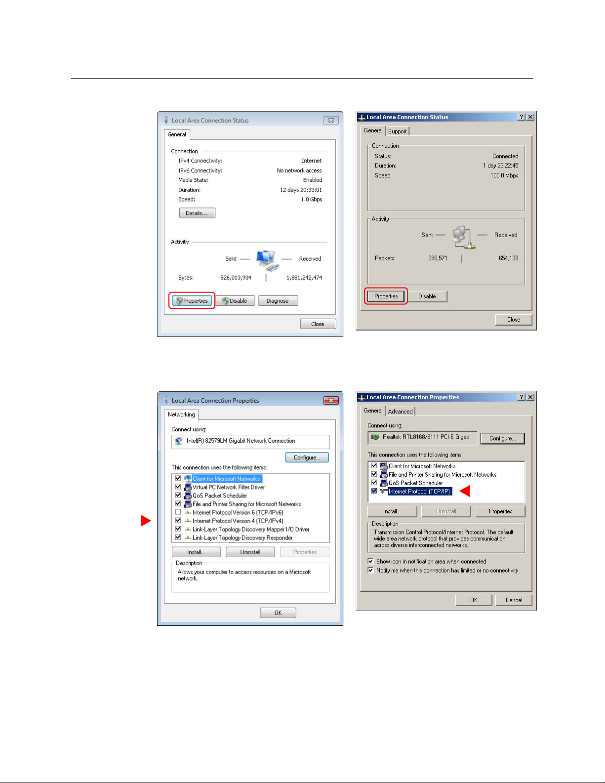
The ‘Local Area Connection Status’ window appears.
Windows 7
Windows XP
Windows 7
Windows XP
Miranda Router Configurator
User’s Guide
If multiple tabs display, select the General tab. Click Properties.
3 The ‘Local Area Connection Properties’ window appears.
Select Inter net Protocol Version 4 (TCP/IPv4) or Internet Protocol (TCP/IP). Click Proper-
ties.
3
Page 14
Getting Started
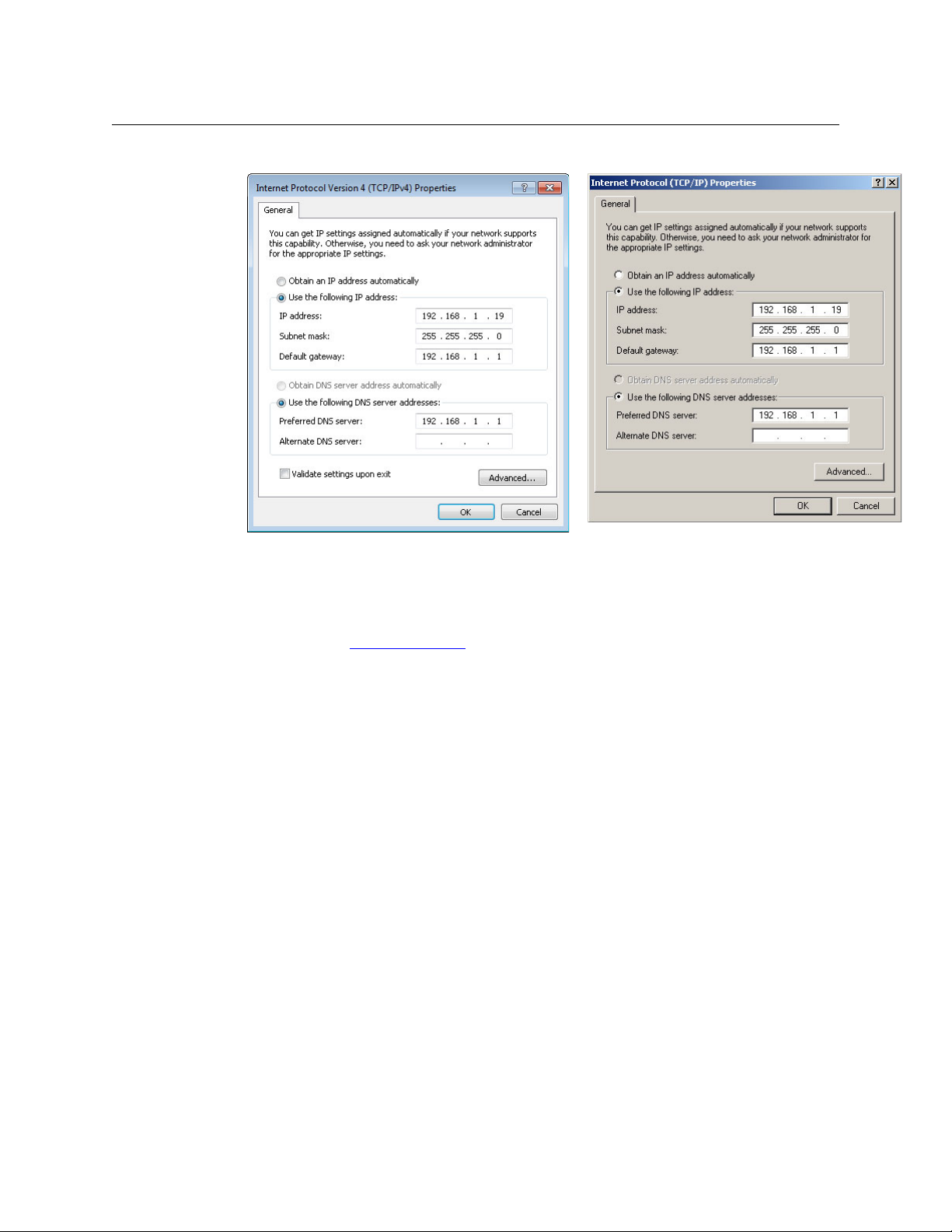
Windows 7
Windows XP
Assigning IP Address to PC
4 The ‘Internet Protocol (TCP/IP) Properties’ window appears.
5 Choose Use the following IP address and enter an IP address for your PC. It is recommended
that you use the IP address 192.168.1.19. The IP address must be unique on the MRC network. The subnet mask must be 255.255.255.0.
(For details, see T
he MRC Network on page 139.)
6Click OK to save your changes.
4
Page 15

How to Create Additional Subnets
Windows 7
Windows XP
1 Starting from step 5 in the preceding procedure, click Advanced.
Miranda Router Configurator
User’s Guide
2Click Add . . . and enter an IP address.
3 Repeat step 2 for additional IP addresses.
4 After adding IP addresses for your subnets, click OK.
5
Page 16
Getting Started
Installing MRC
Installing MRC
MRC is available on the SB0033 Software and Documentation CD. To install MRC:
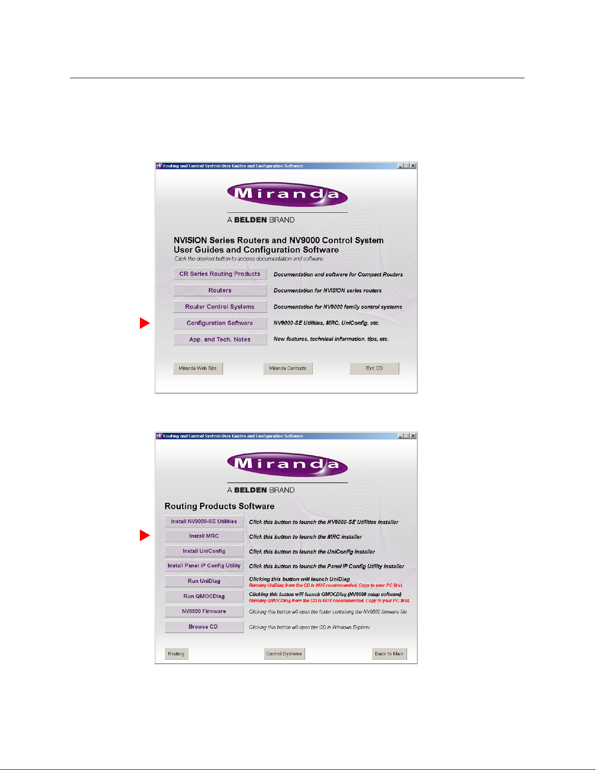
1 Insert the CD in your CD drive.
Wait for the initial screen:
Click the ‘Configuration Software’ button.
2 The ‘Routing Products Software’ page appears:
Click ‘Install MRC’.
6
Page 17
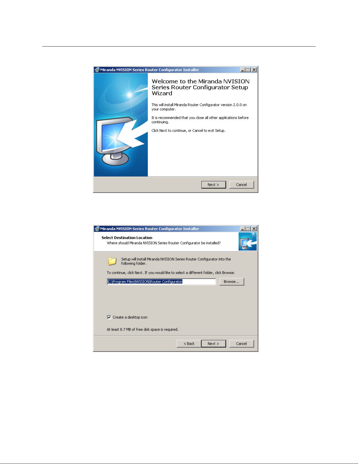
3 The installation script will begin to run:
Miranda Router Configurator
User’s Guide
Click ‘Next’.
4 A window appears in which you can designate the location on your PC in which to install
MRC:
The window presents the default location. If you prefer another location, click ‘Browse’ to
navigate to a different folder.
Uncheck ‘Create a desktop icon’ if you do not want an MRC shortcut to appear on your PC
desktop.
The window tells you the disk space needed for the installation. If you do not have that
much space, the installation will fail.
When you are satisfied with the pathname and options, click ‘Next’.
7
Page 18
Getting Started
Installing MRC
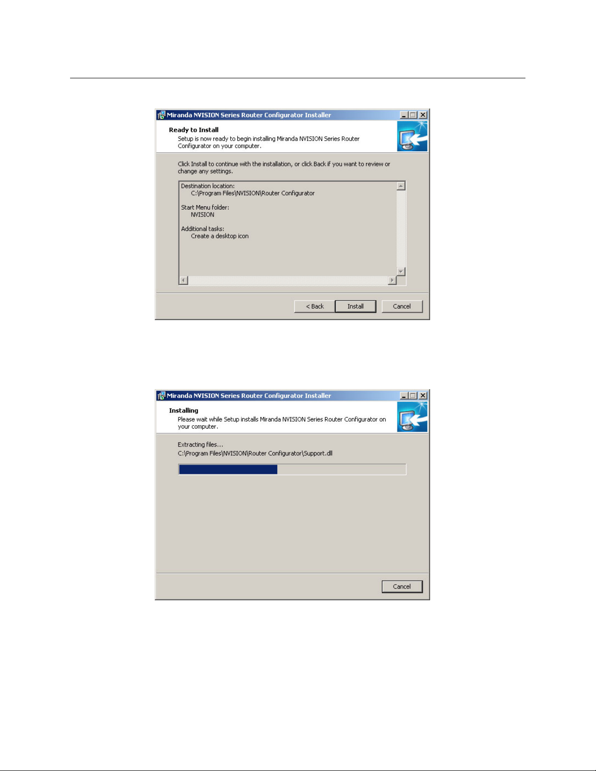
5 A confirmation window appears:
If the options presented are not correct, click ‘Back’ to go back to the previous window and
re-enter a pathname or change options.
Otherwise, click ‘Next’ to start the installation or click ‘Cancel’ to stop the installer.
When you start the installation, a progress window appears:
8
Page 19
Miranda Router Configurator
User’s Guide
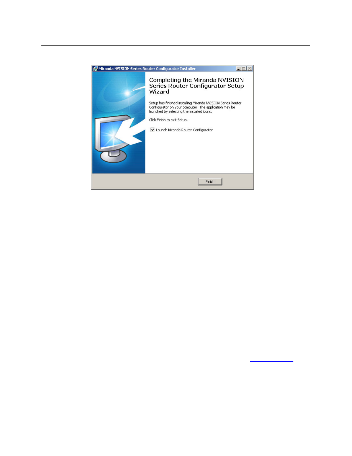
6 After several seconds, the installation will complete. The completion window appears:
Uncheck ‘Launch Miranda Router Configurator’ if you do not want to run MRC immediately.
7 Click ‘Finish’.
Verifying Your Installation
After you have installed MRC, launch MRC by clicking its desktop icon or selecting
‘NVISION > Miranda Router Configurator’ from the PC’s list of programs. Then, from MRC’s navigation pane, click ‘Ethernet Settings’ to open the ‘Ethernet Settings’ page and view a list of
control cards in the network.
Click ‘Refresh List’ in the ‘Ethernet Settings’ page.
Examine the list of control cards and note whether any of the following problems exist:
• No entries in the list.
Either you have no network, the network is not properly connected to the PC, or there are no
control cards on the network. Ensure that the PC has an Ethernet connection to the Ethernet
switch for the network.
Click the ‘Network Interfaces’ button in MRC’s ‘NVISION Series Products’ page to determine to
which subnets your configuration PC is connected.
One of your router frames might be disconnected or receiving no power. Check Ethernet
connections, power connections, and power supplies of the router.
• Entries read IP Conflict. There might be duplicate IP addresses on the network. To correct this,
find and change IP address so that all IP addresses are distinct. See T
page 139.
he MRC Network on
9
Page 20

Getting Started
Installing MRC
• Entries read Different Subnet. These entries are for devices that are detectable by MRC, but
are not on a currently available subnet. To view available subnets, hover your mouse over
“Different Subnet.” A popup context menu of available subnets appears.
There are several corrections for this type of entry:
• Change the IP address of the device to the current subnet.
• Change the IP address or subnet of the configuration PC.
• Change the IP address in some other way, but leaving the device on some other subnet.
• Physically remove the device from the network by disconnecting the connecting cables.
Correct any problems and click ‘Refresh List’ on the ‘Ethernet Settings’ page to view an updated
list of devices. Once the network is functioning properly, you are ready to use MRC to perform
configuration tasks.
10
Page 21
Using MRC
The Miranda Router Configurator (MRC) is a software application used to set up and modify
configuration settings and perform diagnostics for NV8500 series hybrid routers.
MRC also has limited (i.e., incomplete) support for other routers and for other devices that have
control cards. Routers other than NV8500 series hybrid routers should be configured with
UniConfig. In particular, NV8500 series standard routers should be configured with UniConfig.
Topics
Overview of MRC . . . . . . . . . . . . . . . . . . . . . . . . . . . . . . . . . . . . . . . . . . . . . . . . . . . . . . . . . . . . . . . . . . . . . . . . . 11
MRC Tools . . . . . . . . . . . . . . . . . . . . . . . . . . . . . . . . . . . . . . . . . . . . . . . . . . . . . . . . . . . . . . . . . . . . . . . . . . . . . . . . 13
Selecting a Control Card . . . . . . . . . . . . . . . . . . . . . . . . . . . . . . . . . . . . . . . . . . . . . . . . . . . . . . . . . . . . . . . . . . 15
Saving Configuration Changes . . . . . . . . . . . . . . . . . . . . . . . . . . . . . . . . . . . . . . . . . . . . . . . . . . . . . . . . . . . 17
The MRC Interface . . . . . . . . . . . . . . . . . . . . . . . . . . . . . . . . . . . . . . . . . . . . . . . . . . . . . . . . . . . . . . . . . . . . . . . . 18
Setting Preferences . . . . . . . . . . . . . . . . . . . . . . . . . . . . . . . . . . . . . . . . . . . . . . . . . . . . . . . . . . . . . . . . . . . . . . . 23
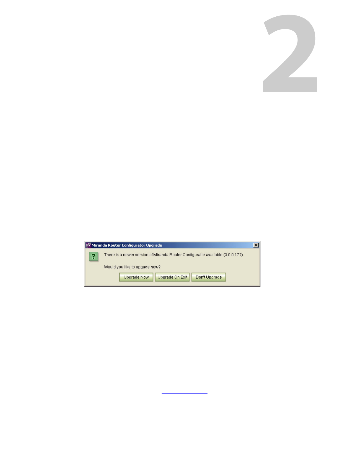
MRC is periodically updated at Miranda with new features and functionality. Miranda automatically notifies you of available updates whenever your copy of MRC is connected to the Internet
for longer than 5 minutes.
To obtain an update, click Upgrade Now or Upgrade On Exit on the dialog window that
appears. If you do not want to upgrade, click Don’t Upgrade. The next time you launch MRC, the
download options will appear again, allowing you to upgrade at that time.
Overview of MRC
MRC runs on a PC and communicates with the router’s control cards over Ethernet.
MRC configures the router by applying settings to the router’s control card, by updating firmware in the I/O cards, crosspoint cards, and monitor cards, and by changing settings in the
EEPROM on the router’s backplane. MRC communicates with the control cards through Ethernet
connections.
Some third-party router control systems use a serial protocol and require that serial connections
be configured within MRC. (See Serial Port Settings
NVISION Ethernet protocol is always available through the router’s Ethernet connections.
NVISION serial protocol is always available through the CTRL 2 serial ports. Other protocols can
be active on the CTRL 1 ports. The routers have two sets of ports, one for the primary control
on page 66.)
11
Page 22

Using MRC
Overview of MRC
card and one for the secondary (redundant) control card in the router frame. For details about
the serial ports, see the router’s documentation. The control card allows only one third-party
protocol to be loaded at any one time.
MRC fully supports these NV8500 series hybrid routers (i.e., those that use an EM0833 control
card):
NV8144 144 × 144
NV8140 144 × 288
NV8280 288 × 576
NV8576 576 × 1152
NV8576-Plus, single frame 576 × 576
NV8576-Plus, expanded (two frames) 1152 × 1152
For information about the NV8500 routers, see the NV8500 Series Routers User’s Guide.
MRC has limited support for all other NVISION series routers and some other devices that have
NVISION series control cards, such as the EC9535.
An NV8500 series standard router (one that uses an EM0666 control card), and all other routers
are configured primarily by UniConfig or UniDiag configuration software. Contact Miranda for
more information.
12
Page 23
Miranda Router Configurator
Navigation
Pane
Work Area
User’s Guide
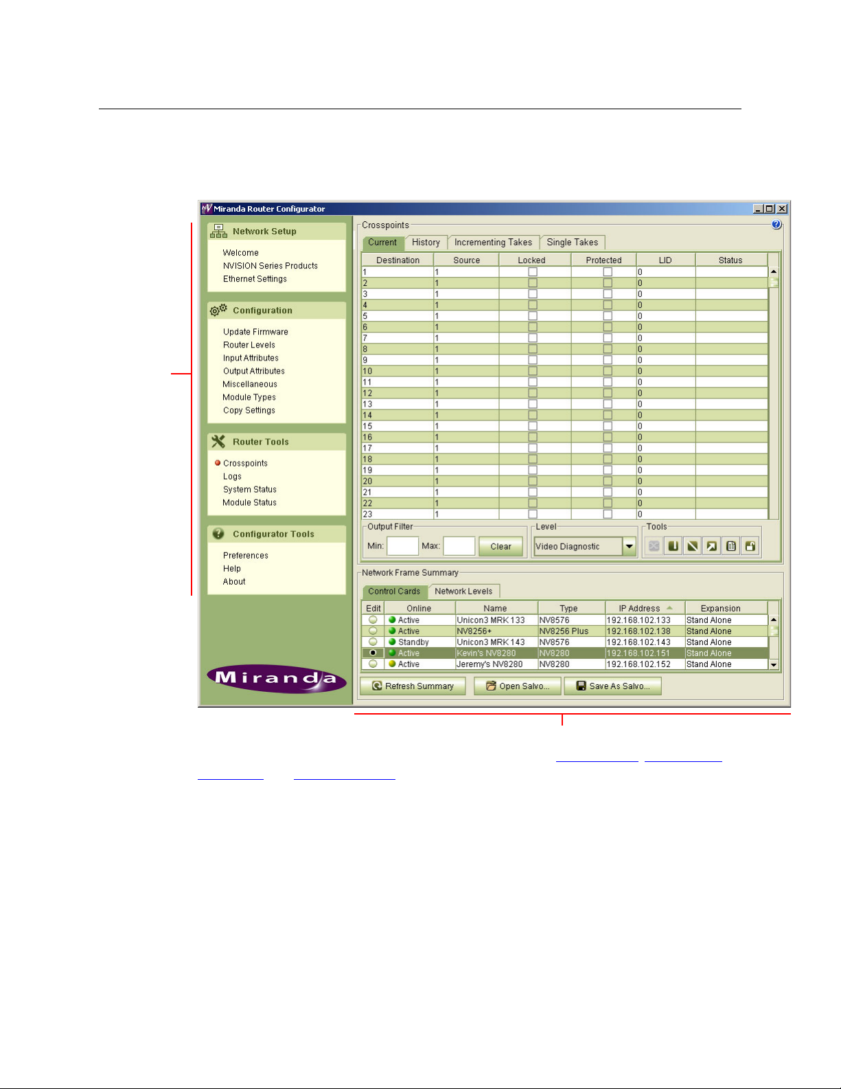
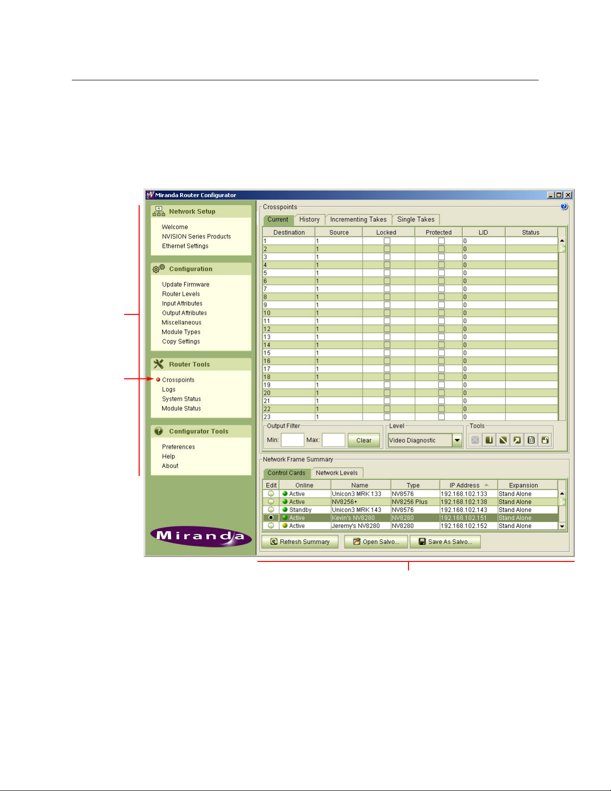
MRC Tools
After you launch MRC, it presents a window with two parts: a navigation pane to the left, and a
work area to the right.
The navigation area is divided into sections based on function: network setup, configuration,
router tools
perform specific tasks.
, and configurator tools. Within each of these sections are links to pages (tools) that
13
Page 24
Using MRC
Overview of MRC
Network Setup
The ‘Network Setup’ section provides an introduction to MRC, lists all devices detected by MRC
and supports control card management, including adding and removing, and creating “virtual”
cards, locking configurations, and updating IP addresses. These are its pages:
Page Description Related Topic
Welcome A brief introduction to MRC and a summary of MRC
tools.
NVISION Series
Products
Ethernet
Settings
Lists all NVISION series devices known to MRC. NVISION Series Products Page
Manages IP addresses, virtual control cards, and adding or removing cards.
—
on page 128
Ethernet Settings Page on
page 129,
he MRC Network on
T
page 139
Configuration
The ‘Configuration’ section provides tools for configuring a router by making settings in the
router’s control card. Control card configurations can be copied to another control card. These
are its pages:
Page Description Related Topic
Firmware Lists firmware, version information, and uploads new
firmware to control cards and IOXM cards.
Router Levels Configures router levels. A router control system uses
level information to communicate with the router
control cards and to manage the switching matrix.
Input Attributes Specifies “output embedder” settings for NV8500
hybrid router inputs.
Output
Attributes
Miscellaneous Manages router serial settings. Also configures which
Module Types Specifies which module belongs in a specific card
Copy Settings Either copies selected control card settings from one
Sets parameters for individual outputs. Different
video and audio formats require different switch
points to prevent switching artifacts.
Also makes reference settings.
router frame is main and which are expansion frames
for expanded routers.
slot in an NV8500 hybrid router frame. Allows for initial setup verification and future alarming if a module
is removed or an incorrect module is installed.
physical control card to another physical control card
or creates a “virtual” control card whose settings can
be imported to physical control cards.
Firmware Page on page 28
Routing on page 141.
Router Levels
page 37.
on page 144.
Levels
Signal Types
Input Attributes Page
page 48
Output Attributes Page
page 50.
Video Fields and Frames
page 145.
Redundant and Dual Video
References on page 149
M
iscellaneous Page on
page 65
Module Types
opy Settings Page on
C
page 78
on page 143
Page on
on
on
on
on page 71
14
Page 25
Miranda Router Configurator
User’s Guide
Router Tools
After your router is configured, you can use the pages of the ‘Router Tools’ section to monitor
system status and module status, manage the switching matrices, and view alarm messages.
These are its pages:
Page Description Related Topic
Crosspoints Displays, tests, and updates crosspoints. Testing and
updating is done by performing “takes.”
Logs Displays startup log data and current running log
data for a selected control card.
System Status Displays the “health” of a router’s active or standby
control card, frame, alarms, power supplies and fans.
The page also displays the overall health of all the
modules in the system and the state of the slot configuration.
Module Status Lists the modules physically installed in a router
frame and gives the location and “health” of each
module.
Crosspoints Page on page 84
Routing on page 141
Module Types on page 71
System Status
Module Status Page
page 117
on page 115
on
MRC automatically updates system and status information every 8 seconds.
Configurator Tools
The ‘Configurator Tools’ section provides preference settings, application version information,
and online Help.
Page Description Related Topic
Preferences Allows you to re-enable warning messages that you
have disabled.
Help Opens MRC’s online help. This entry in the ‘Configu-
rator Tools’ section does not correspond to an MRC
page.
About Presents version information, disclaimers, copyright,
and other product information.
These are “tools” that help you use MRC.
Selecting a Control Card
To perform configuration tasks, you must generally select a router’s control card.
When a control card is selected, it is selected in all MRC pages associated with that control card.
For example, if you select a control card on the Control Cards tab in the ‘Crosspoints’ page, that
same control card is automatically selected on all pages in which the Control Cards tab appears.
Setting Preferences on
page 23
—
—
15
Page 26
Using MRC
Selecting a Control Card
Typically, control cards are selected from the Control Cards tab. However, on the ‘Switch Points’
page and ‘Module Types’ page, only hybrid routers are configurable so it is the Hybrid Routers
tab that you use.
How To Select a Control Card
In the ‘Network Frame Summary’ section, click the Control Cards tab (or the Hybrid Routers
tab) to bring the page forward. Then click the radio button on the row listing the control card
you want. Control cards are identifiable both by name and by IP address.
Note: merely clicking on a row listing a control card highlights the row, but does not select the
control card.
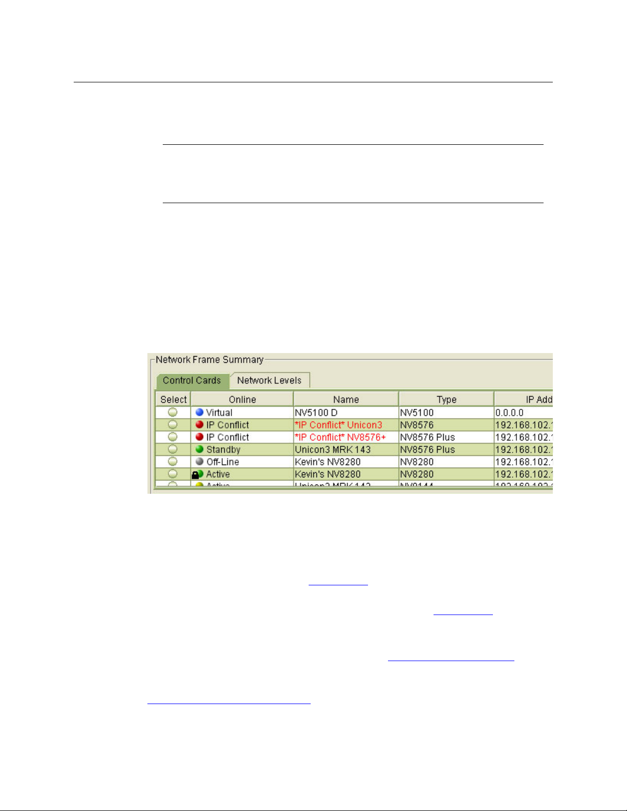
Control Card State Indicators
Control cards are listed one per row. On each row, a colored dot appears in the Online column.
IMPORTANT
Each control card in a router must be configured separately and identically.
With two control cards, one control card is active and the router can remain operational
while configuration changes are being made to the inactive control card.
16
The color of the dot indicates the state and type of card, as follows:
• Green — the control card is functioning normally. Communication between MRC and the
router is good and without interruption.
• Yellow — the control card is in an “unhealthy” state even though no interruption in commu-
nication between MRC and the router has occurred. You can open the ‘System Status’ page
to view diagnostic messages. (See System Status
on page 115.)
• Red — the control card is in a faulty state and all communication has been stopped. You can
open the ‘System Status’ page to view the extent of failure. (See System Status
on page 115.)
• Grey — the control card is offline and MRC cannot communicate with it.
• Blue — represents a virtual control card. A “virtual” control card is one that does not physi-
cally exist but for which there is a configuration. (See Creating Virtual Control Cards
page 133.)
A (black) lock icon indicates that a control card configuration has been locked. For details, see
Locking and Unlocking Configurations
on page 136.
on
Page 27
Refreshing the Control Card Display
In general, all control card information that displays in MRC is current. However, any time you
physically add or remove a control card from a router frame, you should click Refresh Summary.
Doing so ensures that changes in the router frame are communicated to MRC.
You can click Refresh Summary at any time.
Saving Configuration Changes
Configuration settings are stored in non-volatile memory (EEPROM) on the control card. The
EEPROM stores all configuration settings entered through MRC, but not crosspoint data.
Crosspoint data are stored on the control card in battery-backed RAM. Each control card has its
own memory and must be configured separately. All control cards of a router must have identical configurations.
Changes made in MRC are not automatically applied to the control card. For your changes to
take effect, you must click Update Control Card.
You can continue to use MRC while a control card updates.
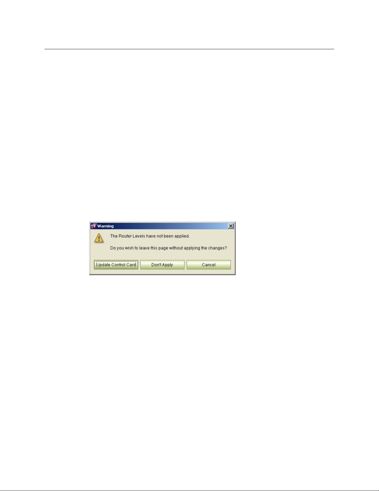
If you make changes and do not click Update Control Card, MRC will display a warning window
providing you with three options.
Miranda Router Configurator
User’s Guide
Click the option you want:
• Update Control Card — save all changes made in the current session and send the changes
to the control card.
• Don’t Apply — close the current page without saving any changes.
• Cancel — Return to the currently open page with all changes still displaying. Changes are
not sent to the control card.
17
Page 28
Using MRC
Navigation
Pane
Orange
dot
Work Area
The MRC Interface
The MRC Interface
The MRC window is divided into two main sections. In the left-hand section is the navigation
pane containing links to pages within MRC. To open a page, click a link in the navigation pane.
The corresponding page displays in the right-hand section.
An orange dot appears on the navigation pane to the left of the link indicating that the page is
open.
Using Tabbed Tables
All pages of the ‘Configuration’ and ‘Router Tools’ sections have a ‘Network Frame Summary’ at
the bottom of the page. The summary section is divided into tabs. To bring a tab to the front,
click the tab title.
Only tables that apply to the tasks to be performed appear in that particular page.
18
Page 29

Miranda Router Configurator
User’s Guide
The following is a list of all tabs that display in the Network Frame Summary:
• Control Cards — lists all control cards in the MRC system. This tab is used to select a control
card to configure.
• Hybrid Routers — used to select a control card in a hybrid router frame. When this tab
appears, functions are restricted to hybrid router frames.
• All Control Cards — lists all control cards in the MRC system. This tab is used for information
only; control cards cannot be selected in this tab. On pages where this tab appears, control
cards have been filtered to display on either the Hybrid Routers tab or the Video Routers
tab.
• Network Levels — lists all levels in the MRC system and their associated parameters. This tab
is for information only.
See Levels on page 144.
• Video Routers — used to select a control card in a video router frame. When this tab
appears, functions are restricted to control cards installed in video router frames.
(There are no tabs for audio routers or machine control routers.)
Each row of a tabbed table represents a single control card (or a single level). The table’s
columns either allow the selection of a control card or provides details about the control card or
the level listed on that row.
The following list describes the columns that appear in the tabbed tables:
Tabbed Table Column Description
‘Control Cards’
or
‘Hybrid Routers’
or
‘Video Routers’
Edit / Select Click the radio button to select the control card listed on that row.
Online Indicates whether the control card is currently active and commu-
nicating with the router control system. When the entry says
‘Ac ti ve’, the control card is the currently active card.
When the entry says ‘Standby’, the card is the inactive (on standby)
card.
The term ‘Virtual’ indicates a virtual control card. (See Creating Vir-
tual Control Cards on page 133.)
Name The name assigned to the router frame in which the control card is
installed.
Type The router model number, such as NV8280.
IP Address The IP address currently assigned to the control card.
Expansion Indicates whether the control card is installed in an expanded
router.
‘Stand Alone’ indicates that the frame is not connected to another
frame.
‘Expanded - Main’ indicates that the router is an expanded router
and the frame is the main frame.
‘Expanded - Expansion’ indicates that the router is an expanded
router and the frame is an expansion frame, not the main frame.
(See Expansion Settings
on page 69.)
19
Page 30
Using MRC
The MRC Interface
Tabbed Table Column Description
Network Levels Level The name of the level.
Signal Type The signal type associated with the level.
Router The router frame to which the level is assigned.
Physical Inputs The physical inputs on the router frame at which the level starts
and ends.
All Control
Cards
Controller
Sources
Physical Outputs The physical outputs on the router frame at which the level starts
Controller Dests Logical numbers in the router control system at which this level
Online Indicates whether the control card is currently active and commu-
Name The name of the router.
Type The router model number, such as NV8280.
IP Address The IP address currently assigned to the control card.
Subnet Mask The subnet mask currently assigned to the control card.
Logical numbers in the router control system at which this level
begins and ends, for source devices.
and ends.
begins and ends, for destination devices.
nicating with the router control system via the network.
‘Active’ in this field means that the control card is currently active
and considered the primary control card.
‘Secondary’ means that the card is the inactive control card.
‘Virtual’ means that the card is a virtual control card (and not a
physical card).
Creating Virtual Control Cards on page 133.
See
Table Commands
When you are using any of the tables, the following functions are available:
• Highlighting — Clicking anywhere in a row changes the color of the row to the highlight
color (deep green, as opposed to white or light green), making the row distinguishable from
the other rows. Highlighting a row does not select the item in the ‘Control Cards’ table, the
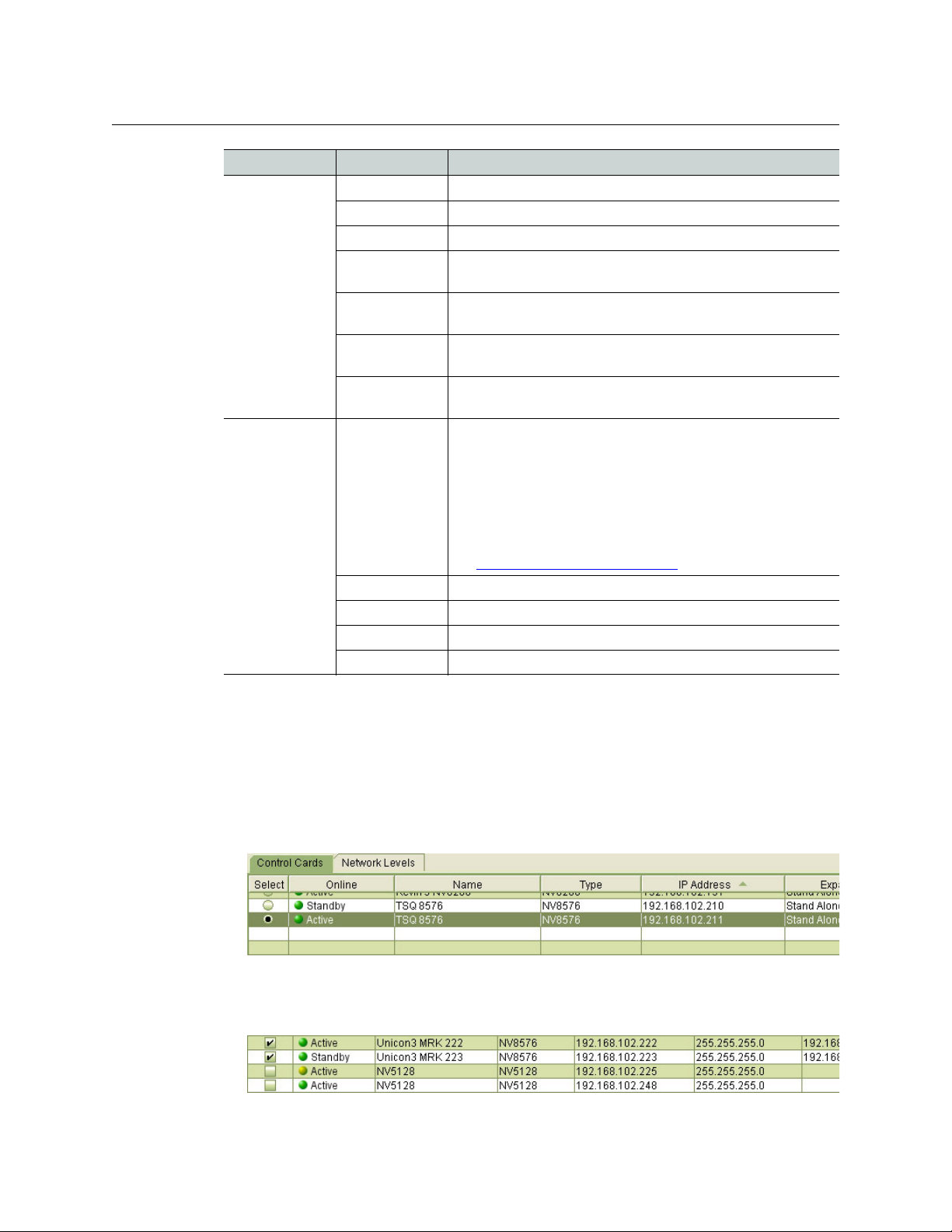
‘Hybrid Routers’ table, or the ‘Video Routers’ table. To select an item represented by a row, such
as a control card, click the radio button in that row:
• Check box — Click a check box to select the item in that row. Click the check box again to
unselect the item. You can check more than one check box at any one time. Checked items
are processed together when you issue a command.
20
Page 31

Miranda Router Configurator
A horizontal arrow cursor appears when you have
selected the column boundary.
User’s Guide
• Radio button — Click on a radio button to select the item in that row. You can select only one
row at a one time using radio buttons.
• Ordering — Clicking the title bar above a column toggle between placing the table in
ascending or descending order on the basis of the values in that column. An arrow appears
indicating the direction of the ordering.
If no arrow appears in the column heading, the table is not sorted with respect to that column.
• Tool tip s — In fields that are enabled for editing, when you hover your mouse over the field, a
“tool tip” appears. “Tool tips” are brief descriptions or instructions.
• Changing column size — Drag the line that divides two columns right or left to increase or
decrease the column width.
• Drop-down lists — Some column fields accept values presented in a drop-down list. These
fields have an arrow beside the field. Click the arrow to view the options in the list. Click on
an option in the list to apply it or to select it.
21
Page 32

Using MRC
The MRC Interface
Keyboard Commands
Standard keyboard and mouse commands are available in MRC.
• Mouse click — Use your mouse to click on an individual row or cell to select it or activate the
field for editing.
• Control (ctrl) key — To select non-consecutive multiple rows or items, press the control key
on your keyboard while using the mouse to click on each additional row or item you want to
select. Each row or item is highlighted. To deselect, click again on the row or item.
• Shift key — To select consecutive multiple rows or items, press the shift key while using the
mouse to click another row or item. All the rows (or items) from the previous selection to the
new row (or item) become selected. The rows or items are highlighted. To deselect, click anywhere in the series of rows or items.
• Right-click — Right-click on a row to use a context menu (if one is available).
For detailed instructions, see your operating system’s user’s guide.
Icons
You can click on an icon or use keyboard shortcuts, when they are available, to perform the
following tasks:
Menu Option Icon Equivalent Keyboard Actions
Copy Press Ctrl + C
Paste Press Ctrl + V
Delete Press the Delete key
Create Salvo —
Save As Salvo Press Ctrl + S
Crosspoint
Jump to Output —
Unlock All —
Range Take Press Ctrl + R
Audio Range Take —
Diagonal Take Press Ctrl + D
a. This might be labeled a “Take” button in MRC. It does not perform
a take, but sends crosspoint data to the router’s crosspoint matrix.
a
—
22
Page 33

Setting Preferences
MRC provides several message windows that warn you of irreversible actions, errors, or conditions. These windows are designed so that users do not perform certain actions that can have
unintended consequences. If you are familiar with MRC, you might find these messages unnecessary. These messages contain a check box that allows you to prevent the messages from
appearing again.
MRC’s ‘Preferences’ window allows you to re-enable the display of one or more of these
messages.
Click ‘Preferences’ (in the ‘Configurator Tools’ section of the navigation pane) to open the ‘Select
Errors, Warnings and Messages to Enable’ window and check or uncheck the ‘Enable’ check box
on the row listing the message that you want to re-enable. Then click OK. Click Cancel if you do
not want to save your changes.
Miranda Router Configurator
User’s Guide
Screen Size
To change MRC’s screen size, drag any corner or edge of the MRC window with your mouse. The
minimum size is 1024 × 768 (pixels).
MRC remembers its screen size and position the next time you launch MRC.
Other Topics
Context Menu
A “global” context menu appears when you right-click within the ‘Control Cards’ table or the
‘Hybrid Routers’ table of most configuration pages:
23
Page 34

Using MRC
Other Topics
The context menu has 3 or 4 options, depending on where you are in MRC. These are the
options:
• Configuration Locked.
This option has a check box. If the box is checked, the configuration of the control card you
have selected is locked.
Click on this option if you want to lock a control card configuration (and it is not already
locked). A warning appears:
Click YES to lock the configuration.
• Reset control card.
Click this option to reset the physical control card.
• Export configuration.
Click this option to save the control card configuration to a .zip file.
• Set Expansion frames.
When you are working with expanded routers (main plus expansion frames), you will work
with the main frame primarily. MRC does not yet have the ability to recognize which frame is
the matching expansion frame.
If you select a main frame, MRC will ask you to identify the expansion frame(s) in the following dialog:
24
You can use the same dialog with the ‘Set Expansion Frames’ command in the context menu.
Page 35

Nomenclature
Certain abbreviations are used throughout MRC:
IOXM Card classification: i
1
TDM
DEM Disembedder (or de-embedder)
EMB Embedder
UI Upper input
LI Lower input
UO Upper output
LO Lower output
SDI Means video (literally, serial digital interface)
SD Standard-definition
HD High-definition
3Gig Video at 2.97 or 2.967 Gb/s.
Means “MADI” (TDM is the way individual MADI signals are transported.)
nput, output, xpt (crosspoint) or monitor
Miranda Router Configurator
User’s Guide
1. Time domain multiplexing.
25
Page 36

Using MRC
Other Topics
26
Page 37

Configuring Routers
When its control card(s) are present in the MRC network, a router can be configured. MRC’s
‘Configuration’ section has several tools with which you can update firmware, create router
partitions, set reference and switch point parameters, govern communication between
connected router frames, and specify the location of modules within the router frame.
Topics
Firmware Page . . . . . . . . . . . . . . . . . . . . . . . . . . . . . . . . . . . . . . . . . . . . . . . . . . . . . . . . . . . . . . . . . . . . . . . . . . . 28
Router Levels
Input Attributes Page
Output Attributes Page
Redundant Crosspoint Page
M
iscellaneous Page . . . . . . . . . . . . . . . . . . . . . . . . . . . . . . . . . . . . . . . . . . . . . . . . . . . . . . . . . . . . . . . . . . . . . . . 65
Module Types
C
opy Settings Page . . . . . . . . . . . . . . . . . . . . . . . . . . . . . . . . . . . . . . . . . . . . . . . . . . . . . . . . . . . . . . . . . . . . . . . 78
The ‘Configuration’ section includes the following tools (or pages): ‘Firmware’, ‘Router Levels’,
‘Input Attributes’, ‘Output Attributes’, ‘Miscellaneous’, ‘Module Types’, and ‘Copy Settings’. Each
page lets you perform a specific set of configuration tasks:
Page . . . . . . . . . . . . . . . . . . . . . . . . . . . . . . . . . . . . . . . . . . . . . . . . . . . . . . . . . . . . . . . . . . . . . . . . 37
. . . . . . . . . . . . . . . . . . . . . . . . . . . . . . . . . . . . . . . . . . . . . . . . . . . . . . . . . . . . . . . . . . . . . 48
. . . . . . . . . . . . . . . . . . . . . . . . . . . . . . . . . . . . . . . . . . . . . . . . . . . . . . . . . . . . . . . . . . . 50
. . . . . . . . . . . . . . . . . . . . . . . . . . . . . . . . . . . . . . . . . . . . . . . . . . . . . . . . . . . . . . 56
. . . . . . . . . . . . . . . . . . . . . . . . . . . . . . . . . . . . . . . . . . . . . . . . . . . . . . . . . . . . . . . . . . . . . . . . . . . . 71
Task Description Related Topic
Upload the latest
router firmware
Create levels (partitions) for switching
Set switch points A “switch point” is a point in time at which a router output is to
Change redundant
crosspoint settings
Add serial port settings
The router’s firmware is essential to its correct operation. Firmware affects communication between the router control system and router control cards. The ‘Firmware’ page updates the
firmware currently loaded on control cards, I/O cards, monitor
cards, and crosspoint cards in the router frame.
Router control systems use level information to communicate
with the router and manage the crosspoint connections. Use
the ‘Router Levels’ page to configure levels.
be switched from its current input to a new input. The ‘Output
Attributes’ page lets you set different video and audio format
switch points to prevent switching artifacts.
Configure crosspoint priority or manually (or remotely) switch
the redundant crosspoint.
Some third-party router control systems require serial ports to
be configured for proper communication. The ‘Miscellaneous
Settings’ page governs serial port settings. This page also
establishes which frame is the “main” frame in an expanded
router.
Firmware Page
on page 28
Router Levels
Page on page 37
Output
Attributes Page
on page 50
Redundant Crosspoint Page on
page 56
iscellaneous
M
Page on page 65
27
Page 38

Configuring Routers
Firmware Page
Task Description Related Topic
Force embedders to
be on, as needed
Assign module types
to module slots
Copy control card
settings to another
control card
Firmware Page
The ‘Firmware’ page is a means to upload selected firmware to all the control cards, input and
output cards, monitor cards, and crosspoint cards installed in the router. A firmware update is a
rare but vital event. Control cards must have the correct firmware loaded to execute commands
from the router control system successfully and to communicate with MRC successfully. Firmware is pre-installed on the router at the factory.
This is the ‘Firmware’ page:
At times, it is necessary to force embedders (in hybrid output
cards) on for the duration of a route. You can specify for which
input ports this is done.
The ‘Module Types’ page assigns card types to the router’s card
slots. This helps verify that your initial installation is correct and
later warns you about potentially incorrect module changes.
This page makes configuration of multiple control cards easier.
The ‘Copy Settings’ page copies control card settings to
another physical card or to a “virtual” control card or from a
“virtual” control card.
Input Attributes
Page on page 48
Module Types
page 71
C
opy Settings
Page on page 78
on
28
Page 39

Miranda Router Configurator
User’s Guide
Grass Valley is continually improving firmware to make control card and other active module
communication the most effective and reliable it can be. In addition, changes in router configurations may necessitate new firmware be uploaded. Grass Valley makes an effort to notify
customers when firmware updates become available. You can also contact Grass Valley technical support at any time to verify that you have the latest versions.
IMPORTANT
Updating firmware causes the router’s control card to reset. A firmware update takes the
router offline. It is recommended that firmware updates be performed during a service
period when the router can be scheduled to be offline.
WAR NIN G
All routers must be disconnected from all router control systems during a firmware
update. If they are not disconnected, the router control system will continue to communicate with the router, interfering with the firmware update.
Using the Firmware Page
To update firmware in a router, you must select its control card (in the ‘Control Card’ table at the
bottom of the ‘Firmware’ page). If the router has two (or more) control cards, you must perform
the same updates for each control card.
After you select a control card, click Choose at the upper right to select a firmware (.rf) file. See
Choosing a Firmware file
When you select a control card, MRC scans all modules in the router frame and lists the currently
installed firmware versions in the ‘Firmware’ page. With respect to your selected firmware file, if
a module contain firmware for which a different version is available, MRC displays the module
name, version number, and description in bold red text.
on page 30.
29
Page 40

Configuring Routers
Firmware Page
Each column in the table provides the following options or information:
Column Description
Update Check the check box to select the module for updating. (This is just to select the mod-
Needs Update A check mark appears in the check box when a different version of the firmware exists
Name Type and location of the module being updated. (See Nomenclature
Version The version of the firmware currently loaded in the module.
Description A general description of the module, which may include its part number, router
Choosing a Firmware file
When it becomes necessary to update your router’s firmware, your Grass Valley service technician will send you a .rf file with new firmware. Store the .rf file in your PC’s file system. When you
perform the firmware update, a copy of the firmware is stored in the CF card on the router’s
control card. The CF card will store up to 5 recent versions of the firmware. It will also store the
names of all previous versions. If you ever want to revert to a previous version, you can choose
one of the previous versions available.
To select a firmware file, click ‘Choose’ at the upper right corner of the ‘Firmware’ page. The
‘Choose Router Firmware’ dialog appears. There are two choices in the dialog:
• Used on this control card.
• All available.
ule. Checking the box does not perform the update.)
for a particular module and updating is needed. Modules for which this box is
checked show red text.
on page 50.)
Note: if the CPLD or ROM displays in red, the chip must be updated, but cannot be
updated through MRC. Contact Grass Valley Technical Support
model, signal type, or function. (See Nomenclature on page 50.)
30
‘Used on This Control Card’ Option
The ‘Used on this Control Card’ option lists all previous versions, available or unavailable, on the
CF card:
You can choose any that is listed as “on router.” Click the radio button in the ‘Select’ column to
do so. Then click ‘OK’.
Page 41

Miranda Router Configurator
User’s Guide
‘All Available’ Option
If your intention is to install new firmware, choose ‘All Available’ and click the ‘Browse for RF
file . . .’ button to navigate to the folder that holds your new .rf file. Select that file.
The file now appears in the list and its availability now reads “MRC Cache.”
Click the radio button in the ‘Select’ column for the new firmware to select it. Then click ‘OK’.
The phrase “In Use” in the ‘Active’ column indicates which firmware is currently active in the
control card.
You could also choose any of the earlier firmware files listed if you wanted to revert to a previous
firmware version.
The ‘Available’ Column
Five different message can appear in the ‘Available’ column of the ‘Choose the Router Firmware’
dialog. The messages concern the availability of .rf files. This is what they mean:
• Not Available
You (or someone) had once used MRC to install this .rf file, but the file cannot be found in
known locations.
• On Router
The .rf file is located in the flash memory of the router’s control card. This message is typical
of .rf files that have been recently uploaded to the control card but are not available on your
PC. (They might be available on someone else’s PC.)
• On PC
The .rf file is located on your PC. This message is typical of .rf files that you are about to
upload.
• MRC Cache
The .rf file is located in MRC’s cache (on your PC). This message is typical of .rf files that you
have recently uploaded to the control card, but are not
memory of the router’s control card.
— for whatever reason — in the flash
31
Page 42

Configuring Routers
Firmware Page
• MRC & Router
Context Menu
When you have chosen the ‘All Available’ option, the dialog has a context menu. The context
menu has a single command ‘Delete from RF Cache’. This command is enabled for .rf files
present in MRC’s .rf file cache (on your PC). If you want to delete a file from the cache, right-click
a row in the list of .rf files that reads ‘MRC Cache’ or ‘MRC & Router’ in the ‘Available’ column:
Click the ‘Delete from RF Cache’ command. Respond ‘Yes’ to the confirmation message:
The .rf file is located both in MRC’s cache (on your PC) and in the flash memory of the router’s
control card. This message is typical of .rf files that you have recently uploaded to the control
card.
Updating Firmware
A large router can have hundreds of modules. Selecting which modules to update can be overwhelming. The ‘Firmware’ page provides you with several tools that make it easy to select
specific firmware. You can choose to update individual modules, all modules, or create a rule to
select only modules that match specific parameters.
The page has 4 selection buttons:
• ‘Select All’ — selects all modules.
• ‘Select None’ — deselects all modules
• ‘Select if Needs Update” — Selects only those modules that need updates.
• ‘Select . . .’ — Select modules by criterion. (This button opens a dialog in which you create a
“rule”, that is, specify the criterion.)
Selecting modules does not perform the update. You must press the ‘Update Firmware’ button
at the button of the page to start the update of selected modules:
Modules can take a significant amount of time to update. MRC shows a progress bar
(percentage complete) for modules that are updating.
Creating a Module Selection Rule
Click the ‘Select . . .’ button to open a dialog in which to create a rule for selecting modules. A
rule consists of one or more matching expressions. A module becomes selected either when it
matches any or when it matches all of the expressions. Only those modules that match the rule
are selected.
32
Page 43

Miranda Router Configurator
User’s Guide
The dialog contains one or more rows of entry fields. Each row has 3 entries that form an
expression:
The first entry field is a drop-down list in which you can select a target for matching. The targets
are names of the columns in the firmware table:
• ‘Needs Update’
• ‘Name’
• ‘Version’
• ‘Description’
• ‘Firmware’
The second entry is a drop-down list of matching behaviors. The third entry is the pattern to
match. In many cases, this is a text string that you can type. In most cases, the behavior is either
“contains” or “does not contain.” In the preceding illustration, the matching rule is
Description contains “EM0815”
Using this expression, modules are selected when their description field contains the string
“EM0815”.
The patterns and matching behaviors differ when you select different targets. For instance, if
you select ‘name’ instead of ‘Description’ for the target, the pattern drop-down list displays
entries from the ‘Name’ column.
33
Page 44

Configuring Routers
Firmware Page
You can add additional matching expressions by clicking the “+” box in the dialog. You can
delete a specific expression by clicking the “–” box in its row. When you have more than one
expression, the rule changes appearance slightly:
An additional drop-down menu appears where you may specify that the rule applies when a
module matches any expression or when it matches all the expressions.
In all cases, when you click OK, MRC performs the selection that you specify. You are free to
perform another selection if you make a mistake. MRC does not execute the update until you
click the ‘Update Firmware’ button at the bottom of the ‘Firmware’ page.
How To Create a Selection Rule
1Open the ‘Firmware’ page.
2 Click ‘Select . . .’ The ‘Select Firmware’ dialog appears:
The first drop-down list is the target. The second drop-down list is the behavior. The third
drop-down list (or entry field) is the pattern.
3 Select a target, behavior, and enter a pattern. Click the plus sign (
another parameter, action, and term. To remove a row, click its minus sign (
+) to add a row and select
–).
34
Page 45

Miranda Router Configurator
User’s Guide
The following is a list of targets and accompanying behaviors:
Tar ge t Action Meaning
Needs Update is checked
is not checked
Name contains
does not contain
Version contains
does not contain
Description contains
does not contain
Firmware is on
is not on
Generate a match if the module has (or does not have) a check
mark in the ‘Needs Update’ column.
Generate a match if the name of the module contains (or does
not contain) the text string you type.
Generate a match if the version of the module contains (or
does not contain) the selected version. You can specify a substring as the pattern.
Generate a match if the description field of the module contains (or does not contain) the selected text pattern. You can
specify a substring as the pattern.
Generate a match if the module is of the type you choose as
the pattern: that is, a control card, an input card, an output
card, monitor card, or a crosspoint card.
4 Choose how the modules that match the rule are selected. Because the choices are “radio
buttons,” you can select only one option:
Method Description
Select only modules
that match
Select only the first
module that matches
Add matches to current selection
Only modules that match the rule are selected. This the default method.
Only the first module that matches the rule is selected.
Any modules that match a (new) rule are added to the previously selected
modules.
5Click OK.
How To Update Firmware
1 Go to the ‘Firmware’ page. From the Control Cards table at the bottom of the page, click a
“radio button” to select a control card. Be certain it is the control card you want.
When you select a control card, MRC lists, in the upper part of the page, all the modules of
the router frame in which the control card is situated.
2 In the ‘Router Firmware File’ region click Choose to locate and select the firmware file you
want to use for the update. (Its file extension is .rf.)
The ‘Choose New Firmware’ dialog appears.
Click the ‘Browse for RF file . . .’ button to locate a new firmware file. Then choose the firmware file from the list. (You can choose an earlier version of firmware stored on the control
card if you want.)
See Choosing a Firmware file
on page 30 for more information.
35
Page 46

Configuring Routers
Firmware Page
3 In the ‘Current Firmware Versions’ region, select all the modules you want to update at one
4 (Optional) To force all selected modules to be updated, uncheck the ‘Only update if versions
5Click Update Firmware (at the bottom of the page). MRC starts the update of all selected
time.
Check individual check boxes in the ‘Update’ column,
Or, click Select All,
Or, click Select If Needs Update
to select only modules with a check mark in the ‘Needs
Update’ column,
Or. click Select . . . to select modules by a criterion,
Or, click Select None. (Note that when no modules are selected, an update cannot occur.)
are different’ check box. When this option is checked, modules are updated only when the
firmware version is different from the firmware currently loaded on the module.
modules.
One or more progress bars appear in the ‘Description’ field of modules being updated. When
a module is completed, “Update succeeded” appears in place of the progress bar.
When the update of all modules is complete, MRC displays a log of the update:
36
Note
If MRC fails to update certain cards, try the update again for those cards. If the update
fails repeatedly, contact Grass Valley Technical Support
.
Note
In practice, it is advisable to update each control card first, and then update IOXM cards.
6 Repeat this procedure for each control card of the router. (An expanded NV8576-Plus typi-
cally can have 4 control cards, 2 in each frame.)
Do not repeat this procedure of IOXM cards. It is not necessary and very time-consuming.
Page 47

Miranda Router Configurator
User’s Guide
Viewing and Saving Update Logs
Every time a module’s firmware is updated, a description of the update is logged in the MRC
database. To view a log of past updates, click View Past Update Logs (at the bottom of the ‘Firmware’ page). The button remains greyed out (i.e., inactive) until you have performed an update
that can be logged.
How to View and Save an Update Log
1Go to the ‘Firmware’ page.
2Click View Past Update Logs, at the bottom of the page. The ‘Update Status Log History’
window appears.
3 (Optional) To print the currently displaying log, click Print.
4Click Save. The ‘Save’ window appears.
Click Browse to specify where you want to save the file, enter a file name, and then click
Save to save the file and close the window.
5Click Close.
Router Levels Page
Creating levels is an important part of the configuration process. Router control systems use
level information to communicate with the router and manage the crosspoint connections. To
view and set router levels, use the ‘Router Levels’ page.
Note
The levels governed by this page are termed “physical levels” or “partitions” in other
software. The “physical” levels defined in this page must also be defined identically in
the router’s description in NV9000-SE Utilities.
Further, NV9000-SE Utilities defines what are called “virtual” levels. The levels governed
by this page are not “virtual” levels.
(Physical) levels are boundaries within the switching matrix that organize switching within the
router. Each level is assigned one or more signal types that represent the signals being switched
within that level. Signals can be switched only within the same level. The signal types assigned
to the level must match the actual signals being routed.
Remember that every router configuration must have at least one level and signals can be
switched only within a level, not between levels.
It is in the ‘Router Levels’ page that you can specify certain features of the NV8500 hybrid
routers:
• The null audio source.
• The basic pass-through audio source.
• Sixteen audio sources for extended pass-through.
See Special Audio Sources
on page 43.
37
Page 48

Configuring Routers
Special
Audio
Sources
Physical
Levels
Network
Frame
Summary
Router Levels Page
Using the Router Levels Page
This is a typical ‘Router Levels’ page:
38
Fig. 3-1: Router Levels Page (Sample Showing an NV8280)
It has 3 main sections:
• Special audio sources.
This section allows you to define the following items:
• The null audio source.
• The basic pass-through audio source.
• Sixteen audio sources for extended pass-through.
These are discussed in Special Audio Sources
The information displayed in the special audio sources section changes if you have
on page 43.
selected a ‘Synchronous Stereo Audio’ level of an NV8500 series hybrid router.
For other routers, this section is disabled.
• Physical level list.
Use this section to define the physical levels of your router.
Page 49

Miranda Router Configurator
User’s Guide
• Network Frame Summary.
This section has two tabs: ‘Control Cards’ and ‘Network Levels’. Use the ‘Control Cards’ tab to
select a router control card for the router you want to configure. (The ‘Network Levels’ tab
provides information only.)
Network Frame Summary
This section has two tabbed lists and two important buttons:
Use the ‘Control Cards’ tab to select a router control card for the router you want to configure.
(The ‘Network Levels’ tab provides information only. Its use is not required to perform any tasks.)
The buttons at the bottom of the section are:
• Refresh Summary
Click this button to ensure that the list of control cards contains current information.
• Update Control Card
Click this button after you have made changes to the configuration of the selected router
control card.
Physical Levels
To view or set levels, select a control card in the ‘Control Cards’ table of the router frame
summary.
When you have selected a control card, MRC displays its current level settings in the ‘Crosspoint
Ranges for Level Settings’ table in the middle of the page.
An invalid signal type can exist only in control cards configured with older versions of MRC.
See A
dding and Updating Levels on page 41.
39
Page 50

Configuring Routers
Router Levels Page
This illustration shows typical levels for a hybrid NV8280.
The table’s columns provides the following information:
Column Description
Level Number assigned to the level. A unique number is automatically assigned. If
Physical Input Start The physical input connector at which the level starts.
Physical Input End The physical input connector at which the level ends.
Controller Source Start The logical port number at which the level begins, for sources.
Controller Source End The logical port number at which the level ends, for sources. This number is cal-
Physical Output Start The physical output connector at which the level starts.
Physical Output End The physical output connector at which the level ends.
Controller Destination
Start
Controller Destination
End
Signal Type The signal type to be supported by the level. See Signal Types
you change the level, keep in mind that the level numbers must all be different.
culated. You cannot change it.
The logical port number at which the level begins, for destinations.
The logical port number at which the level ends, for destinations. This number
is calculated. You cannot change it.
on page 143.
40
Note: strictly speaking the “controller source” numbers and “controller destination” numbers are
really port numbers in the router control system, not source and destination numbers. Sources
and destinations in the router control system are aggregates of router ports, often spanning
multiple routers.
Level Types
There are many physical level types (corresponding to signal types as the column is labeled in
the table). The levels from which you may choose depend on the router you are configuring.
For the NV8500 family routers, these are the available level types:
• Asynchronous AES. Use a partition of this type if your NV8500 router has AES cards installed.
• Digital Video. Use a partition of this type for video signals of any type (e.g., 3Gig, HD, or SD).
• Monitor. Use a partition of this type to support input and output monitoring. (Monitor cards
must have been installed in your router.)
• Synchronous Audio. Use a partition of this type for NV8500 hybrid routers. Embedded (and
disembedded) audio and MADI signals are supported by this partition type.
Page 51

Miranda Router Configurator
User’s Guide
• Synchronous Stereo Audio. Use a partition of this type of you want to support the switching
of stereo pairs. (The ‘Synchronous Audio’ level supports independent switching of audio
channels. (This is called “mono” switching.) You may superimpose a stereo level on a “mono”
level; that is, the two levels may overlap).
The range values that specify a stereo partition are half those of a corresponding “mono”
partition because, in stereo, the audio channels are paired.
If you have defined, and selected, a stereo audio partition, the information displayed in
the ‘Pass-Thru Shuffle Audio Source table changes.
Special Case for NV8500 Hybrid Routers
If an NV8500 hybrid router has any MADI cards and uses DHP, you must add 40,000 to the MADI
port numbers in NV9000-SE Utilities. In addition, you must add 40,000 to the natural audio partition size.
If the natural audio partition is 9216 × 18432, then the audio partition for MADI under DHP must
be specified as 49,216 × 58,432 in NV9000-SE Utilities.
You m ust not add 40,000 to the partition size in MRC.
Adding and Updating Levels
Levels are created by specifying a range of inputs and a range of outputs. A range is denoted by
a starting number and an ending number. Inputs and outputs are referenced in two ways: (1) as
physical input connections and physical output connections on the router, and (2) as logical
ports (supporting sources and destinations) in the router control system.
The physical input and output numbers in the table represent the physical connections on the
router. The logical ports in a router control system always map to physical connections, but the
numbering might not be the same. For example, the router control system might have port 1
mapped to physical input 17, not physical input 1.
For information about router control system source and destination numbering, refer to your
router control system’s documentation.
IMPORTANT
Every control card in a router must be configured separately, but identically.
The levels defined in MRC must match the levels defined in your router control system.
If you change or delete a level in MRC, you must make a corresponding change in the
router control system’s configuration.
For each level, MRC generates a list of available signal types automatically according to the type
of router. These are available in the drop-down lists in the ‘Signal Type’ column of the table.
(See Signal Types
on page 143.)
How to Create or Update a Level
1 Go to the ‘Router Level’ page. From the Control Cards table at the bottom of the page, select
a control card. The level data for that control card appear in the ‘Crosspoint Ranges for Level
Settings’ table.
2 If you want to add a level, click Add Level.
41
Page 52

Configuring Routers
Router Levels Page
3 If you are updating a level, locate its table row.
4 In the ‘Signal Type’ entry for that row, select a signal type from the drop-down list. You must
5 Enter the remaining parameters for the level. Click in a cell to activate the editable field:
A new row appears in the table (unless the table is already at its maximum size).
do this before setting other parameters. The signal type determines the range of values for
the physical inputs and outputs. The signal type options vary according to the router type.
Column Description
Level By default, the next sequential number is assigned to a level, starting at 1.
Physical Input Start The range specified by the start and end values depends on your inten-
Physical Input End
Controller Source Start The logical port number in the router control system that maps to the
Controller Source End The logical port number in the router control system that maps to the
Physical Output Start The range specified by the start and end values depends on your inten-
Physical Output End
Controller Destination
Start
Controller Destination
End
tions, but cannot exceed the maximum range of the router.
physical input starting number.
physical input ending number. This number is calculated. You cannot
change it.
tions, but cannot exceed the maximum range of the router.
The logical port number in the router control system that maps to the
physical output starting number.
The logical port number in the router control system that maps to the
physical output ending number. This number is calculated. You cannot
change it.
6 Repeat steps 1–5 for other levels.
7Click Update Control Card
to send the level information to the control card.
8 Each control card must be configured separately and all control cards in the router must
have the same level settings.
Repeat this procedure for each control card in the router frame.
Or, copy the control card’s configuration to the remaining control card(s) in the router. See
C
opy Settings Page on page 78.
9 Each control card in the router must be configured separately and identically.
Either repeat this procedure for each control card in the router . . .
Or, finish making all changes to the control card and then copy its configuration to the
remaining control card(s) in the router. See C
opy Settings Page on page 78.
Deleting Levels
You can delete levels at any time, but be careful. Heed the following warning:
Every control card in a router must be configured separately, but identically.
The levels defined in MRC must match the levels defined in your router control system.
If you change or delete a level in MRC, you must make a corresponding change in the
router control system.
42
Page 53

Miranda Router Configurator
User’s Guide
Remember that every router configuration must have at least one level and signals can be
switched only within a level, not between levels.
How to Delete a Level
1 Go to the ‘Router Level’ page. From the Control Cards table at the bottom of the page, select
a control card.
2 In the ‘Crosspoint Ranges for Level Setting’ table, click on the row representing the level to
select it. Then click Delete Level.
(In the confirmation window, click YES.)
3 Repeat step 2 for other levels you want to delete.
4Click Update Control Card
5 Each control card in the router must be configured separately and identically.
Either repeat this procedure for each control card in the router . . .
Or, finish making all changes to the control card and then copy its configuration to the
remaining control card(s) in the router. See C
to send the level information to the control card.
opy Settings Page on page 78.
Special Audio Sources
The special audio sources section of the page applies only to NV8500 hybrid routers, and
then only to those hybrid routers that use disembedder/embedder output cards.
The special audio sources are artificial (or fictitious) sources that are recognized, and used, by
router firmware to perform special functions.
The special audio sources do not produce audio of any kind. What they do is signal to the router
control card that it must perform specific operations with regard to embedded audio output.
Because the special audio sources are fictitious, it is recommended, for any of the special audio
sources, that you specify one of the unused audio ports in your router. (They are included in the
port numbering, but there is no circuitry for those ports.) Note that a port committed to a
special audio function cannot be used as a normal audio port.
Regarding unused audio port numbers: always choose unused audio port numbers that are
greater than the number of video input ports of the router. Unused port number between
1152 and 2304 will work well for any NV8500 router. Figure 3-1 on page 38 for example
shows that audio ports in the range 1281–1296 were used.
The special audio sources are involved in the logic of disembedder/embedder cards. A card
output receives either (1) generated silence, (2) audio from the router’s audio matrix, (3) audio
disembedded from the video at the output.
Important: the different special audio sources
all have different values. The router will still function, but it might not function the way you
expect. In such cases, the router’s behavior is not easily definable.
— unless the fields are disabled or blank — must
43
Page 54

Configuring Routers
Router Levels Page
Regions of the Special Audio Section
The title of this section is ‘Audio Settings for Level’:
Fig. 3-2: Special Audio Section
The section has 3 parts that allow you to define the following items:
• The null audio source.
• The basic pass-through audio source.
• Sixteen audio sources for extended pass-through.
The port numbers in this section must all be unique. You may not have duplicates.
Null Audio Source
When used (by a control panel operator), a “null audio source” lets the router control card know
that null audio is required for an audio output (in an embedder or disembedder/embedder
output card).
The port you specify as the null audio source is not a source of audio. This “null audio source”
tells the router to use, instead, silence from an internal silence generator.
Null audio is generated silence, but is more than just silence because when all the channels
of an audio group are null, the group is omitted from the output altogether.
See Embedded Group Control
How to Specify a Null Audio Source
1 Check the ‘Null Audio Source’ check box. If this box is not checked, the null audio source field
is greyed out.
2 Enter one of the audio input ports of the hybrid router in the null audio source field. The field
actually accepts values in the range [0–65,535] but only valid audio port numbers will work
properly. Specify one of the unused audio ports of the router’s disembedder cards (or MADI
cards). Otherwise, if you specify a normal port, that port cannot be used for any real input.
Always choose an unused audio port number that is greater than the number of video
input ports of the router. Unused port number between 1152 and 2304 will work well for
any NV8500 router.
Uncheck the ‘Null Audio Source’ check box if you do not want to use null audio.
3 Perform other changes in the ‘Router Level’ page as required and click the ‘Update Control
Card’ button at the bottom of the page.
To be usable, the null audio source must also be configured in NV9000-SE Utilities.
on page 151 for more information.
44
Page 55

Miranda Router Configurator
User’s Guide
Pass-Through Audio Sources
Pass-through audio means audio taken from the video presently routed to the output.
When used (by a control panel operator), a “pass-through audio source” lets the router control
card know that pass-through audio is required for an audio output (in an embedder or disembedder/embedder output card).
A port you specify as a pass-through audio source is not a source of audio. When a control panel
operator chooses a pass-through audio source, what he or she means is “use the audio from the
video routed to the output.”
There are two forms of “pass-through” audio:
• Basic — governs all 16 audio channels of a video source as a unit.
The title of this field is ‘Pass-Thru Audio Source’.
When a control panel operator specifies this audio source, all 16 audio channels of the disembedder/embedder output are taken from the video routed to that output.
Under basic pass-through, the mapping of audio channels from the video source to the output is identity. That is, audio channel n goes to output channel n, where 1 < n < 16.
• Extended — allows you to specify 16 individual pass-through audio sources, one for each
audio output channel.
The title of this region is ‘Pass-Thru Shuffle Audio Source’.
The appearance and meaning of the fields of this region change when you select a
‘Synchronous Stereo Audio’ level. See Stereo vs. Mono
Under extended pass-through, the mapping of audio channels from the video source to the
output is any-to-any. That is, the source channels can be shuffled.
There is no check box that enables the pass-through audio sources of this section. Leave
blank the fields for those channels for which you do not want a pass-through audio source.
When a control panel operator specifies one of the pass-through audio sources that you
specify in this region, the audio source channel specified by the pass-through selection is
sent to the selected audio channel of the output.
For example, if, as in Figure 3-2, audio source 1283 is specified for channel 3, when a panel
operator “takes” audio port 1283 to the output, what happens is that audio channel 3 of the
video routed to the output is taken (or “passed through”) to the chosen audio channel of the
output.
The disembedder on the output cards makes those audio channels available. The multiplexer on the output card does the individual channel selection.
To be usable, any pass-through audio sources you define must also be configured in
NV9000-SE Utilities.
See P
ass-Through Sources on page 152 for additional information.
, following.
Stereo vs. Mono
The format of the ‘Pass-Thru Shuffle Audio Source’ table changes when you have selected a
‘Synchronous Stereo Audio’ level.
45
Page 56

Configuring Routers
Router Levels Page
If you have not selected a stereo level, or if you have none defined, the table has 16 entries as
shown here:
If you have selected a defined stereo level, only the first 8 entries of the table are enabled:
Table entries 9–16 are disabled. Entries 1–8 provide pass-through audio support for 8 stereo
pairs. Channels 1 and 2 are paired, channels 3 and 4 are paired, and so on.
The pass-through ports you specify are specified according to the mono port numbering.
Any ports you have used for table entries 9–16 (for mono pass-through) are disabled for stereo
pass-through.
How to Specify a Basic Pass-Through Audio Source
1 Check the ‘Pass-Thru Audio Source’ check box. If this box is not checked, the pass-through
audio source field is greyed out.
2 Enter one of the audio input ports of the hybrid router in the pass-through audio source
field. The field actually accepts values in the range [0–65,535] but only valid audio port numbers will work properly. We recommend that you specify one of the unused audio ports of
the router’s disembedder cards (or MADI cards). Otherwise, if you specify a normal port, that
port cannot be used for any real input.
Always choose an unused audio port number that is greater than the number of video
input ports of the router. Unused port number between 1152 and 2304 will work well for
any NV8500 router.
Uncheck the ‘Pass-Thru Audio Source’ check box if you do not want to use basic passthrough audio.
3 Perform other changes in the ‘Router Level’ page as required and click the ‘Update Control
Card’ button at the bottom of the page.
46
Page 57

Miranda Router Configurator
User’s Guide
How to Specify Extended Pass-Through Audio Sources for a Mono Partition
1 Ensure that you have not selected a ‘Synchronous Stereo Audio’ partition.
2 Go to the ‘Pass-Thru Shuffle Audio Source’ table. Take note of its contents. The table has 16
entries, each corresponding to an audio output channel (of any output of any disembedder/
embedder card in the router). The channels are identified.
3 Choose a channel. Enter one of the audio input ports of the hybrid router in the ‘Source’ field
for that channel. We recommend that you specify one of the unused audio ports of the
router’s disembedder cards (or MADI cards). Otherwise, if you specify a normal port, that
port cannot be used for any real input.
Always choose an unused audio port number that is greater than the number of video
input ports of the router. Unused port number between 1152 and 2304 will work well for
any NV8500 router.
The port must be in the range of the ‘Synchronous Audio’ inputs. The field must not be
blank.
Leave the ‘Source’ field blank if you do not want to use pass-through audio for that channel.
4 Repeat step 3 for any other audio channels for which you want pass-through audio.
5 Perform other changes in the ‘Router Level’ page as required and click the ‘Update Control
Card’ button at the bottom of the page.
How to Specify Extended Pass-Through Audio Sources for a Stereo Partition
1 Select a ‘Synchronous Stereo Audio’ partition.
2 Go to the ‘Pass-Thru Shuffle Audio Source’ table. Make a written note of its contents. The
table has 8 entries, on the left side of the table, each corresponding to a (stereo) pair of audio
output channels (of any output of any disembedder/embedder card in the router). The
channel pairs are identified.
3 Choose a channel pair. Enter one of the audio input ports of the hybrid router in the ‘Source’
field for that channel. The field actually accepts values in the range [0–65,535] but only valid
audio port numbers will work properly. We recommend that you specify one of the unused
audio ports of the router’s disembedder cards (or MADI cards). Otherwise, if you specify a
normal port, that port cannot be used for any real input.
Always choose an unused audio port number that is greater than the number of video
input ports of the router. Unused port number between 1152 and 2304 will work well for
any NV8500 router.
Leave the ‘Source’ field blank if you do not want to use pass-through audio for that channel.
4 Repeat step 3 for any other channel pairs for which you want pass-through audio.
5 Perform other changes in the ‘Router Level’ page as required and click the ‘Update Control
Card’ button at the bottom of the page.
47
Page 58

Configuring Routers
Input Attributes Page
Input Attributes Page
The ‘Input Attributes’ page applies only to NV8500 hybrid routers.
The page allows you to specify, for any video input, whether the embedder of any output to
which the input is routed is to be forced ON.
Normally, the audio embedder of an output is enabled or disabled automatically according to
internal switching rules. See Switching “Rules”
The table in this page gives you a choice for each input.
• Force embedder ON.
• Use switching rules.
Caution: if your router control system uses DHP to control the router, make sure that the setting
is ‘Use Switching Rules’ for all inputs.
This is a view of the page for an expanded NV8576-Plus:
on page 149.
48
The page has two regions. At the bottom is a ‘Network Frame Summary’ that contains tabbed
tables. In the ‘Hybrid Router’ table, you can select the control card of a router to configure.
Page 59

Miranda Router Configurator
User’s Guide
The upper region contains a table of input ports and their settings and a graphic image of the
router, front or back. If you select an input in the table, the input card is highlighted (in yellow) in
the graphic. You might have to scroll the graphics window to see the selection.
Choose a radio button below the graphic to switch between front and back views.
The table shows the following information for each input:
Column Description
Input The video input port number.
Output embedder
Attributes
Location The input slot in which this input is found.
Module If a slot is empty, this field is blank. Otherwise, the field shows the type of the
A drop-down menu exists for each input: There are two choices in the menu:
‘Force embedder ON’ — force the output’s embedder to be enabled.
‘Use Switching Rules’
Note that embedders in disembedder/embedder output cards are always on.
card in the slot, for that input.
— use the embedder’s automatically generated state.
Note
If you hover your mouse over an input in the input list, MRC displays a small information
window, showing the input card’s slot number and the audio ports that would correspond to
the input if the input slot held a disembedder card:
The audio ports display regardless of whether the input card is a standard card, disembedder
card, or MADI input card.
Card Selection
Use standard click, shift-click, and control-click methods to make input port selections in the
input list.
You can also click an input card in the drawing (front or rear) to select it. When you do so, the
card is highlighted in yellow and the first input of that card is highlighted in the input list.
Clicking an input card causes any previously selected inputs to become unselected.
Caveats
This table treats the entire input space of the router uniformly. Where there are disembedder
input cards and MADI input cards in the router, some of the video input ports listed do not exist
in the router. For empty slots, obviously, the input ports do not exist.
It is harmless to assign a value to a non-existent port (and MRC lets you do it) but you should not
forget that some of the ports listed might not exist in the router.
49
Page 60

Configuring Routers
Output Attributes Page
Nomenclature
The ‘Location’ column uses abbreviations for card locations. This is what they mean:
• I-nnn — input card in slot nnn (for NV8144s and NV8280s)
• LI-nnn — input card in slot nnn of the lower bay (for NV8576s and NV8576-Pluses)
• UI-nnn — input card in slot nnn of the upper bay (for NV8576s and NV8576-Pluses)
• Main: LI-nnn — input card in slot nnn of the lower bay of the main frame (for expanded
• Main: UI-nnn — input card in slot nnn of the upper bay of the main frame (for expanded
• Expansion: LI-nnn — input card in slot nnn of the lower bay of the expansion frame (for
• Expansion: UI-nnn — input card in slot nnn of the upper bay of the expansion frame (for
The ‘Module’ column also uses abbreviations. (See Nomenclature
Context Menu
NV8576-Pluses)
NV8576-Pluses)
expanded NV8576-Pluses)
expanded NV8576-Pluses)
on page 50.)
You can change input port settings on an individual basis. Use standard click, shift-click, and
control-click methods to make your selection.
You can also select any number of inputs and use the context menu to modify all the selected
inputs at one time. This is the context menu:
In the context menu, you can (1) select all inputs or (2) select all inputs of a particular type.
When you have selected one or more inputs, use the ‘Set selection: Output embedder’
command, and its submenu, to set their values.
Output Attributes Page
A “switch point” is the point in time in which a video output will be switched from its current
input to a new input. Switching of audio associated with the video signal is synchronized with
the video switch. Different video and audio formats require different switch points.
You can set switch point parameters for individual outputs in the ‘Output Attributes’ page.
The attributes table controls the type of switch point, but not the actual moment in time of the
switch, relative to the reference signal. Diagnostic equipment or specialized software is required
for that.
The ‘Output Attributes’ page also has reference signal controls. (Switch points are affected by
the reference signals.)
Reference signals are connected at reference connections on the router frame. Video reference
connects at two ports labeled VIDEO REF1 and VIDEO REF2. These connectors can receive the
50
Page 61

Miranda Router Configurator
User’s Guide
same signal or different signals. If they receive the same signal, the references are considered
redundant. Otherwise they are dual references.
(See Redundant and Dual Video References
Audio reference connects at two ports labeled AES REF1 and AES REF2. One or both connections
are connected to a stable AES source at 48
applied to both connectors, the connection is redundant.
For more information on reference connections, see the router’s documentation.
on page 149.)
kHz (48,000 samples per second). If AES reference is
Additional Information about Video and AES Reference
For information about output attribute settings and how to set them, review the following
material:
• Video Fields and Frames on page 145.
• About Vertical Timing on page 145.
• SMPTE Standards for Switch Point on page 146.
• External References and Switch Point Configurations on page 146.
• Redundant and Dual Video References on page 149.
Using the Output Attributes Page
To view or modify output attributes of video outputs in a router, select a control card for that
router in the ‘Video Routers’ table at the bottom of the page.
The output attributes page cannot be used for the expansion frame of an expanded router. Use
the corresponding main frame to access the outputs of the expansion frame.
When you select a control card, MRC presents (1) reference options and (2) a table of outputs for
the router. For the sake of discussion, we call this the attributes table.
51
Page 62

Configuring Routers
Redundant Reference Dual Reference
Output Attributes Page
This is a sample showing the data for an NV8280:
AES Reference Options
A check in the checkbox in this region means that an external AES reference must be present for
proper switching. If the box is unchecked, an external AES is not required:
If an AES reference is not present, the router uses its video reference. For NV8500 series routers,
an external AES reference is generally not required.
Dual Video Reference Options
In this region of the page, you can choose between redundant or dual video reference. The
contents of the region differ, depending on which you choose:
52
Page 63

Miranda Router Configurator
User’s Guide
You can choose among 3 reference rates. If you choose redundant reference, the reference rate
applies to both video reference ports. If you choose dual reference, you can have different rates
for the two ports.
For your router to work properly, your settings in this page and the actual video reference
connections must match.
See Redundant and Dual Video References
on page 149.
Output Range
The items in this region act as a filter to limit the amount of information displayed in the
attributes table at the right of the window:
There are two buttons in this region:
• Read Outputs
Specify a start and end value, then click this button. MRC displays the outputs in the range
indicated by the start and end values.
• Read All
Click this button to display parameters for all outputs in the router. MRC shows the default
output range to the left of this button.
The Attributes Table
The attributes table shows the following information for each output displayed:
Column Description
Output The output port number.
*Re-clock/Bypass There are two choices in the drop-down menus in this field: ‘Use Re-clocker’
and ‘Bypass Reclocker’.
Bypassing the output’s reclocker retains the input signal’s current rate. This
option is available for standard SD and HD outputs.
This column affects only “Super Wide Band” outputs.
This option is available for standard outputs. Hybrid re-clockers cannot be
bypassed. (The drop-down menu for hybrid reclockers is disabled, and this is
indicated by the down arrow being dimmed.)
HD / SD There are two choices in the drop-down menus in this field: ‘Switch on SD Line’
and ‘Switch on HD Line’.
Choose Switch on SD Line for SD (or analog video) signals. Choose Switch on
HD Line for HD signals.
53
Page 64

Configuring Routers
Output Attributes Page
If you are configuring an NV8256 or an NV8256-Plus, the attributes table has one additional
column:
That is the ‘Field/Frame’ column. In the fields of this column, you specify whether the individual
router outputs are to switch on a field or frame basis.
See Video Fields and Frames
Note
If you hover your mouse over an output in the attributes table, MRC displays a small information
window, showing the output card’s slot number and the audio ports that would correspond to
the output if the output slot held an embedder card:
on page 145.
The audio ports display regardless of whether the output card is a standard card, embedder
card, or MADI output card.
Output Attributes Context Menu
In addition to the drop-down menus for individual outputs, the attributes table provides a
context menu. Right-click anywhere within the table to display the context menu:
The context menu lists 2 settings: Reclock/Bypass and HD/SD.
To apply a setting to a single output, right-click on the output and then choose a setting from
the context menu.
To apply a setting to all outputs, right-click anywhere in the list of outputs and click Select All.
Then make your settings.
For a description of each setting, see How to
Configure Output Attributes on page 55.
54
Page 65

Miranda Router Configurator
User’s Guide
Configuring and Updating Output Attributes
Switch points can be configured for video outputs. MRC displays only fields that apply to the
type of signals a specific router can switch.
To ensure proper switching of video signals require that the router be connected to a video
reference source.
A switch point is accurate only if the input signals to the router are (vertically) timed to the
applied reference signals. The router calculates an output’s switch point using the reference
signal: line 10 for SD or analog signals at 525i, line 6 for SD or analog signals at 625i, and line 7
for all HD and 3Gig standards.
For example, if an input’s line 1 is displaced 100 lines from the reference, the switch occurs at
line 110 (SD, 525i), 106 (SD, 625i), or 107 (HD or 3Gig). However, because of automatic timing in
downstream devices the need for precise timing of sources at the router inputs is usually
unnecessary.
After you have initially configured a number of switch points, you can update the router’s
configuration at any time. Click the Update Control Card button at the bottom of the page to
do so. Changes are immediately written to the control card and affect the router’s switching
matrix.
Note
Every control card in a router must be configured separately, but identically.
How to Configure Output Attributes
1 Go to the ‘Output Attributes’ page. From the Video Routers table at the bottom of the page,
select a control card.
The attributes table controls the type of switch point, but not the actual moment in time of the
switch, relative to the reference signal. Diagnostic equipment or specialized software is required
for that.
2 If your router’s audio signals are locked to an external AES reference, check the ‘Require
External AES Reference’ check box.
3 In the ‘Dual Video Reference Option’ region, select Redundant or Dual:
Redundant
If one fails, the other is used as a fail-over. Choose a video rate that applies to both.
Or
Dual
(The choices for video rates are 1080i, 720p, or 1080p. See External References and Switch
Point Configurations on page 146.)
4 (Optional) Use the Output Range filter to limit the outputs that display:
Enter a start and end output number in the fields provided and click Read Outputs. Only the
outputs in the range you entered are displayed.
Or
Click Read All
— Both VIDEO REF 1 and VIDEO REF 2 ports on the router are used and identical.
— The reference signals can be different. Choose a video rate for each reference port.
to have the page display all outputs.
55
Page 66

Configuring Routers
Redundant Crosspoint Page
5 Define attributes for individual outputs:
Column Options Description
Re-clock / Bypass Use Re-clocker
HD / SD Switch on SD Line
Alternatively, use the context menu to define these parameters for any or all outputs.
6 After you have made the changes you wanted to make, click Update Control Card, at the
bottom of the page, to send your changes to the control card:
7 Each control card in the router must be configured separately and identically.
Either repeat this procedure for each control card in the router . . .
Or, finish making all changes to the control card and then copy its configuration to the
remaining control card(s) in the router. See C
Bypass Re-clocker
Switch on HD Line
Choose to re-clock the signal or to bypass the re-clocker,
retaining the signal’s current rate.
This option is available for standard outputs. Hybrid reclockers cannot be bypassed. (The drop-down menu is disabled for hybrid outputs.)
This column affects only Super Wide Band crosspoints.
Choose Switch on SD Line if the output is SD (or analog
video). Choose Switch on HD Line if the output is HD.
opy Settings Page on page 78.
Redundant Crosspoint Page
The ‘Redundant Crosspoint’ page has two main functions:
• Allow remote switching of a router’s redundant crosspoint card (if it has one).
• Enable or disable automatic switching of the redundant crosspoint module. When auto-
matic switching is enabled and a normal crosspoint card fails, the router’s control card
causes the redundant crosspoint module to take over for the failed crosspoint card.
Normal crosspoint cards can be assigned priority so that if two or more crosspoint cards fail,
the control card will cause the redundant crosspoint module to take over for the normal
crosspoint card of the highest priority.
When switching is automatic, the control card retains the current switchover state even if
power to the router is interrupted.
The left side of the page is for configuration (enabling/disabling automatic fail-over and prioritizing the normal crosspoints). You must click ‘Update Control Card’ if you wish to save the
crosspoint configuration.
The right side of the page is “live.” You can click the buttons in the image of the redundant crosspoint module to effect redundant crosspoint switchover at any time. The image also reflects
any switchovers effected by other operators.
The ‘Redundant Crosspoint’ page offers an additional capability: it can highlight the inputs and
output slots that correspond to a selected crosspoint card.
56
Page 67

Miranda Router Configurator
Crosspoint
View
Priority
List
Network
Frame
Summary
Buttons
Redundant
Crosspoint
Buttons
Router
View, to
Show
Affected
Slots
User’s Guide
This is a sample ‘Redundant Crosspoint’ page, showing the crosspoints for an NV8280:
Fig. 3-3: Redundant Crosspoint Page (Sample for an NV8280)
There are 6 sections in the page:
• Crosspoint view
In this section you can select a crosspoint card (by clicking on the image of it). When you do,
the crosspoint is highlighted in yellow or green and the I/O slots serviced by the crosspoint
are highlighted in the router view in the center of the page.
You can click on the image of the redundant crosspoint to deselect the selected crosspoint
card. Doing so also unhighlights the I/O slots in the router view.
• Priority List
This section includes a check box and a list.
Check the check box to enable automatic switchover of the redundant crosspoint. Clear the
check box to disable automatic switchover.
When an automatic switchover occurs, the redundant crosspoint substitutes for the failing
crosspoint that has the highest priority. It is here in this priority list that you can specify the
57
Page 68

Configuring Routers
NV8144
NV8576, NV8576-Plus
NV8140
Redundant Crosspoint Page
priorities of the different crosspoint card slots in the router. (The number of crosspoint card
slots varies with the router.)
You can change the priority of the crosspoint card slots by selecting one or more entries in
the list and dragging them up or down as required. The entries at the top of the list have
higher priorities; the entries at the bottom of the list have lower priorities. Use standard click,
ctrl-click, and shift-click to select crosspoint slots.
You can also drag your cursor through a number of crosspoint slots to select them.
To move selected crosspoint entries, click on those entries, pause a moment, then drag. The
pause is required to distinguish a move from a drag selection.
• Redundant Crosspoint Buttons
This section shows an image of the button panel of the router’s redundant crosspoint module. The image varies with the router type. Figure 3-3 on page 57 shows the graphic for an
NV8280. These figures shows the graphics for the NV8140, NV8144, NV8576, and NV8576Plus:
58
You can switch the redundant crosspoint manually by clicking one of the crosspoint buttons
in the graphic. The actual operation differs with the router.
The graphic also reflects crosspoint changes caused by other operators.
This section of the ‘Redundant Crosspoint’ page is “live”: clicking on buttons in this section
causes an immediate change in the router’s crosspoint cards. Changes made outside MRC
are reflected in this section in real time.
See Manual Redundant Switchover
on page 59 for details.
• Router View
The router view shows the I/O card slots of the selected router, either from the front or the
rear. When you click on one of the crosspoint cards in the crosspoint view, the router view
highlights the I/O card slots that correspond to the selected crosspoint.
Page 69

Miranda Router Configurator
User’s Guide
• Network Frame Summary
Use the ‘Hybrid Routers’ section of the network frame summary to select the control card of
the router of interest.
The page and its sections of course vary in appearance with the router that is chosen.
• Buttons
There are two buttons at the bottom of the “Redundant Crosspoint’ page: ‘Refresh Summary’ and ‘Update Control Card’.
Click ‘Refresh Summary’ to refresh the list of router control cards in the ‘Network Frame Symmary’ section.
Click ‘Update Control Card’ to save changes to the priority list or the automatic failover
option.
Manual Redundant Switchover
Normally, the redundant crosspoint is in standby operation and the normal crosspoint cards are
all active. If a normal crosspoint card fails, you can cause the redundant crosspoint module to
take over for the failed crosspoint card.
The redundant crosspoint card, the normal crosspoint cards, and the methods for switching the
redundant crosspoint manually differ according to the router involved.
NV8140 Switchover
The NV8140 has 3 crosspoint card slots. As viewed from the front of the router, slot 1 is on the
left, the redundant crosspoint card is in slot 2, and slot 3 is on the right:
ALARM
ACTIVE
POWER
REDUNDANT
OPERATION
ALARM
ACTIVE
POWER
REDUNDANT
OPERATION
PATH
LITE
Usually, the normal crosspoint cards are active and their active LEDs are on and the redundant
crosspoint card is in standby mode, its ‘Active’ LED is off, and its ‘Standby’ button is bright.
If the card in slot 1 fails or you want to remove it from the frame, press the button labeled 1 on
the redundant crosspoint card. Immediately, the redundant card takes over for the card in slot 1.
If the card in slot 1 is still powered up, its ‘Active’ LED turns off. The redundant card’s active LED
ALARM
ACTIVE
POWER
1
STANDBY
REDUNDANT
OPERATION
3
PATH
LITEPATH
LITE
59
Page 70

Configuring Routers
Redundant card standby;
both normal cards active.
Redundant card active and
substituting for card 1
Redundant card active and
substituting for card 3
Redundant Crosspoint Page
turns on, the button labeled 1 turns bright, and the ‘Standby’ button turns dim. The remaining
button turns off.
The same holds true for the card in slot 2.
You can place the redundant card in standby mode by pressing its ‘Standby’ button.
You can do the same kind of switching
in the ‘Redundant Crosspoint’ page. These three figures show the different states of the redundant crosspoint buttons:
— possibly remotely — using the redundant card image
NV8144 Switchover
The NV8144 has 2 crosspoint card slots. As viewed from the front of the router, slot 1 is on the
left and slot 2 is on the right:
The same crosspoint card is used in each slot. One of the cards is active and the other is standby.
If the card in slot 1 fails or you want to remove it from the frame, press the button on the other
crosspoint card. Immediately, the other card takes over for the card in slot 1. If the card in slot 1 is
60
Page 71

Miranda Router Configurator
Card 1 active; card 2 standby Card 1 standby; card 2 active
144 X 144
3Gig
Redundant
XPT
NV8500
ALARM
ACTIVE
POWER
1
2
3
4
7
8
9
10
STANDBY
PATH
LITE
REDUNDANT
OPERATION
ALARM
ACTIVE
POWER
ALARM
ACTIVE
POWER
ALARM
ACTIVE
POWER
ALARM
ACTIVE
POWER
ALARM
ACTIVE
POWER
ALARM
ACTIVE
POWER
ALARM
ACTIVE
POWER
ALARM
ACTIVE
POWER
User’s Guide
still powered up, its ‘Active’ LED turns off and its button turns dim. The second card’s active LED
turns on and its button turns bright.
The same holds true for the card in slot 2.
You can do the same kind of switching
— possibly remotely — using the crosspoint card image
in the ‘Redundant Crosspoint’ page. These two figures show the different states of the crosspoint buttons:
NV8280 Switchover
The NV8280 has 10 crosspoint card slots. As viewed from the front of the router, slot 1 is on the
left and slot 10 is on the far right. The redundant crosspoint module occupies the two middle
slots, numbered 5 and 6:
The normal crosspoints are numbered 1–4 on the left and 7–10 on the right. Usually, the normal
crosspoint cards are active and their active LEDs are on and the redundant crosspoint card is in
standby mode, its ‘Active’ LED is off, and its ‘Standby’ button is bright.
If one of the normal cards (for instance, in slot 3) fails or you want to remove it from the frame,
press the button labeled 3 on the redundant crosspoint card. Immediately, the redundant card
takes over for the card in slot 3. If the card in slot 3 is still powered up, its ‘Active’ LED turns off.
61
Page 72

Configuring Routers
Redundant card standby;
all normal cards active.
Redundant card active and
substituting for card 3
Gray buttons are those that
are disabled while a crosspoint is deactivated.
Redundant Crosspoint Page
The redundant card’s active LED turns on, the button labeled 3 turns bright, and the ‘Standby’
button turns dim.
The same holds true for any of the other crosspoint cards.
You can place the redundant card in standby mode by pressing its ‘Standby’ button.
You can do the same kind of switching
in the ‘Redundant Crosspoint’ page. These two figures show different states of the redundant
crosspoint buttons:
— possibly remotely — using the redundant card image
62
Page 73

Miranda Router Configurator
288 X 288
3Gig
Redundant
XPT
NV8500
ALARM
ACTIVE
POWER
1
2
3
4
7
8
9
10
STANDBY
PATH
LITE
REDUNDANT OPERATION
User’s Guide
NV8576 and NV8576-Plus Switchover
The NV8576 has 10 crosspoint card slots. As viewed from the front of the router, slot 1 is on the
left and slot 10 is on the far right. The redundant crosspoint module occupies the two middle
slots, numbered 5 and 6:
The normal crosspoints are numbered 1–4 on the left and 7–10 on the right. Usually, the normal
crosspoint cards are active and their active LEDs are on and the redundant crosspoint card is in
standby mode, its ‘Active’ LED is off, and its ‘Standby’ button is bright.
Each frame of the expanded NV8576-Plus has the same arrangement of crosspoint cards as the
NV8576 (shown above).
If one of the normal cards (for instance, in slot 2) fails or you want to remove it from the frame,
press the button labeled 2 on the redundant crosspoint card. Immediately, the redundant card
takes over for the card in slot 2. If the card in slot 2 is still powered up, its ‘Active’ LED turns off.
63
Page 74

Configuring Routers
Redundant card standby;
all normal cards active.
Redundant card active and
substituting for card 2
Gray buttons are those that
are disabled while a crosspoint is deactivated.
Redundant Crosspoint Page
The redundant card’s active LED turns on, the button labeled 2 turns bright, and the ‘Standby’
button turns dim.
The same holds true for any of the other crosspoint cards.
You can place the redundant card in standby mode by pressing its ‘Standby’ button.
You can do the same kind of switching
in the ‘Redundant Crosspoint’ page. These two figures show different states of the redundant
crosspoint buttons:
— possibly remotely — using the redundant card image
64
Page 75

Miscellaneous Page
The ‘Miscellaneous’ page manages communication settings for the routers in your system:
Miranda Router Configurator
User’s Guide
NVISION series routers typically use Ethernet connections to communicate with the NV9000
router control system and with MRC. Some third-party router control systems use serial connections and require that serial ports be configured within MRC.
Using this page, you can set the serial communication parameters for your router(s).
Some routers (such as the NV8256-Plus and the expanded NV8576-Plus) have two router frames
operating together. If you are configuring such a router, you can specify whether you are configuring the main or the expansion frame, or whether the frame is a standalone router.
The main frame is the one that is connected to the router control system. The expansion does not
communicate with the router control system, but receives commands from main frame.
A single NV8576-Plus frame can operate as stand-alone router.
For other routers, these issues do not exist and the corresponding portions of the ‘Miscellaneous Settings’ page are greyed out.
Certain NV8500 routers support Sony’s ROT-16 protocol. If your router does, the ROT-16 fields in
the ‘Ethernet Protocol Settings’ section will be enabled.
65
Page 76

Configuring Routers
Miscellaneous Page
Serial Port Settings
Two serial ports on the rear of the router frame, labeled CTRL 1 and CTRL 2, are available for
router control system serial communication.
You can also configure the diagnostic ports (labeled DIAG) on the router frame.
(MRC does not communicate through serial ports.)
A third-party router control system requires a specific protocol. The NVISION router you are
configuring will have the appropriate protocol installed on its control card(s).
The control card supports dual, simultaneous control so that it is possible to connect, for
example, a third-party router control system to CTRL 1 and an NV9000 router control system (or
other devices capable of running NVISION serial protocol) to CTRL 2.
Setting up serial communication does not disable Ethernet communication.
Viewing Serial Port Settings
The ‘Miscellaneous Settings’ page has 3 regions: ‘Router Serial Settings’ and ‘Control Card
Settings’, and ‘Ethernet Protocol Settings’. This illustration shows the settings for an NV8280:
66
For an NV8280, as illustrated here, there are no expansion options, so most of the control card
settings are greyed out.
For certain routers, some options do not apply and those will be disabled (greyed out). For
instance, the NV8500 series routers do not support the rear diagnostic port and that section of
the page will be disabled.
Page 77

Miranda Router Configurator
User’s Guide
Router Serial Settings
The ‘Router Serial Settings’ region provides the following information and options:
• Control 1 and 2 Baud Rate Setting
In this section, specify the Baud rate for both CTRL 1 and CTRL 2. The drop-down menu lists
the acceptable Baud rates. The default is 38400 Baud.
• Control 1 Settings
These settings affect the CTRL 1 serial port.
In the protocol field, you can choose the protocol with which the router communicates with
the control system.
In the second field, you can enable or disable this port. If the port is disabled, the other two
fields in this section are ignored.
In the ‘Reply When’ field, choose one of two values:
• Active only — Reply to control system commands and queries only when the control
card is the active card.
• Always — Always reply.
• Control 2 Settings
These settings affect the CTRL 2 serial port.
The protocol is always ‘NV Serial’.
In the second field, you can enable or disable this port. If the port is disabled, the other field
in this section are ignored.
In the ‘Reply When’ field, choose one of two values:
• Active only — Reply to control system commands and queries only when the control
card is the active card.
• Always — Always reply.
• Rear Diagnostic Port Settings
These settings affect the DIAG serial port.
In the ‘Port Type’ field, choose either RS485 or RS232.
In the Baud Rate field, choose a suitable Baud rate.
(For NV8500 routers, these options are disabled.)
Control Card Settings
The ‘Control Card Settings’ region applies only to certain routers. These are the sections of the
region:
• Expansion Settings
This section becomes enabled if you are configuring an expanded or expandable router
(such as the NV8256-Plus or an NV8576-Plus)
Choose one of the options:
• ‘Stand Alone’ — the router has a single frame.
• ‘Expanded - Main’ — the router has two frames and this one is the main frame.
• ‘Expanded - Expansion’ — the router has two frames and this one is the expansion frame.
67
Page 78

Configuring Routers
Miscellaneous Page
• Local Physical
• Control Card Bus Type
If this section is enabled, enter the starting and ending numbers for the inputs and outputs
of the frame you are configuring. This is a sample for the NV8256-Plus:
(For the NV8576-Plus, this section is disabled.)
When more than one control card is installed in a router, the control cards communicate
using an internal bus.
For certain routers, when the router frame is connected to another frame, communication
between the control cards on the two frames occurs through the 10Base2 connections on
the rear of the router frame. If that is the case for your router, this section will be enabled and
you can choose ‘10BASE2’: This is a sample for the NV8256-Plus:
In the ‘Index’ field, enter a number that serves as a frame “ID.” Each frame of a multi-frame
router must have a unique ID.
• Control Card Date Time
If the control card allows it, you can set the control card’s date and time values.
Check the ‘Use this computer’s date / time’ option if you want to use the date and time value
in your computer. When you click ‘Update Control Card’ — as you must do for any of your
settings to take effect — your computer’s values are sent to the control card. Thereafter the
check box becomes unchecked again.
• Configure Tally Status
You can specify whether the control card reports “effective status” or real status. Place a
check in the ‘Report Effective Status’ check box if panels are to report effective status.
Clear the ‘Report Effective Status’ check box if you want panels to report actual status.
“Effective status” applies to standard input cards (only). Audio sources from standard input
cards are tallied as if they were from a disembedding input card.
“Actual status” applies to disembedder cards or MADI input cards. Here, audio tally consists
of actual audio sources.
Effective Status is enabled by default.
Ethernet Protocol Settings
The ‘Ethernet Protocol Settings’ section has one section and that section is enabled if you are
configuring an NV8500 router that supports Sony’s ROT-16 protocol.
You must (1) check the ‘ROT-16 Protocol’ check box and (2) specify two parameters for the
protocol if you wish to use the protocol.
68
Page 79

Miranda Router Configurator
User’s Guide
These are the two parameters that apply:
• ‘Primary Station IP Address’
This is the IP address of the (Sony ROT-16) server with which the router will communicate.
• Secondary Station ID
This is an ID for the router. The ID is used by the server.
Refer to the Sony ROT-16 literature for further information.
Configuring Serial Ports
If your router is connected a to third-party router control system that requires serial ports, you
must configure the router’s serial ports.
How to Configure Serial Ports
1 Go to the ‘Miscellaneous Settings’ page. From the Control Cards table at the bottom of the
page, select a control card.
2 In the ‘Control 1 and 2 Baud Rate Setting’ section, select a baud rate from the ‘Baud Rate’
drop-down list.
3 In the ‘Control 1 Settings’ and the ‘Control 2 Settings’ sections, set serial port parameters.
In the ‘Protocol’ field, select either NV SERIAL or another installed protocol from the dropdown list. (The only protocol available for CTRL 2 is NV Serial.)
Enable or disable the port.
In the ‘Reply When’ field, select how the control card responds to queries and commands:
• Active only — the control card replies only when it is the active control card.
• Always — the control card replies even when it is not the active control card.
4 (Optional) In the ‘Rear Diagnostic Port Settings’ section, select a port type (RS-485 or RS-232)
and a Baud rate from the drop-down menus.
5Click Update Control Card, at the bottom of the page, to write changes to the control card,
overwriting any previous settings:
6 Each control card in the router must be configured separately and identically.
Either repeat this procedure for each control card in the router . . .
Or, finish making all changes to the control card and then copy its configuration to the
remaining control card(s) in the router. See C
opy Settings Page on page 78.
Expansion Settings
Certain routers comprise more than one frame. The NV8256-Plus and the NV8576-Plus are
examples.
69
Page 80

Configuring Routers
Miscellaneous Page
Two NV8576-Plus frames can be connected to form an “expanded NV8576-Plus” router. A single
NV8576-Plus frame can also operate as a stand-alone router.
When two router frames are connected, one frame is designated as the main frame and one
frame as the expansion frame. The main frame is the one that is connected to the router control
system. The expansion frame does not communicate with the router control system, but
receives commands from main frame.
Any changes made to the main frame’s crosspoints are automatically sent to the expansion
frame ensuring synchronization between the connected frames. Expansion frame configurations should not be updated independently of the main frame.
Each control card on each of the router frames must be configured separately and identically.
For routers with two frames, be sure to set all control cards on one frame as main and all control
cards on the remaining frame as expansion.
How to Set a Frame as Main or Expansion
1 Go to the ‘Miscellaneous Settings’ page. From the Control Cards table at the bottom of the
2 In the ‘Expansion Settings’ section, click a radio button for the frame you are configuring:
page, select a control card (for a router that has two frames).
• Expanded - Main — Designates the frame, for the control card you are modifying, as the
main frame.
• Expanded - Expansion — Designates the frame, for the control card you are modifying,
as the expansion frame.
3 The following settings are optional and do not apply to NV8500 routers:
a In the ‘Local Physical’ section, enter a start and end number for the router’s inputs and
outputs in this frame. This is an example for the NV8256-Plus:
b In the Control Card Bus section, if you router requires it, select the 10BASE2 radio button.
The frames of older two-frame routers, such as the NV8256-Plus, communicate through
their 10base2 connections. Choosing 10BASE2 is appropriate for these routers.
In the ‘Index’ field, enter a number that serves as a frame “ID.” Each frame of a multiframe router must have a unique ID.
70
Page 81

4Click Update Control Card, at the bottom of the page, to write changes to the control card,
overwriting any previous settings.
5 Each control card in the router must be configured separately and identically.
Either repeat this procedure for each control card in the router . . .
Or, finish making all changes to the control card and then copy its configuration to the
remaining control card(s) in the router. See C
Module Types
The ‘Module Types’ page is for NV8500 hybrid routers only. This is evidenced by the ‘Hybrid
Routers’ table at the bottom of the page. The table lists only hybrid routers and you can select
only control cards for hybrid routers in this table:
Miranda Router Configurator
User’s Guide
opy Settings Page on page 78.
71
Page 82

Configuring Routers
Module Types
The ‘Module Types’ page specifies the card types that are installed in the slots of the router or
are to be installed in the router at some future date. That you can specify a module type for a
card that is to be installed helps to ensure that the correct modules are installed in the slots.
The table includes data for all input, output, monitor, control, crosspoint, and power supply
modules. The page displays a picture of the router to the right of the table. When you select a
module, MRC highlights the card location in the picture in yellow. There are two “radio buttons”
under the picture of the router that allow you to view the router from the front or the rear. You
can scroll the router picture to view the card you selected.
Initially, the ‘Module Types’ page creates a list of all modules in your router frame. This is the
‘Module Type Settings’ table. This table has a row for every configurable slot in the router frame.
However, the table also has a filter so that you can restrict the display to slots of a certain type.
Choose one of the entries in the ‘Display’ drop-down menu to apply the filter:
If you are configuring an expanded NV8576-Plus, which has two frames, the table can show the
slots for both the main and expansion frames of the router. In this case, the page has an additional drop-down menu in which to choose whether to display slots for the main frame or the
expansion frame, or both:
Power supplies for the NV8280, NV8576, and NV8576-Plus are external and are not displayed in
the graphic.
Each table row has 3 fields, with the following meaning:
• ‘Location’
The text in this field identifies the slot in the router.
The text in this field is coded to be compact. See Nomenclature
on page 50.
• ‘Present’
A ‘Yes’ or ‘No’ in the check box of this field indicates that a card is present in the slot.
• ‘Module’
The text in this field gives the card type in the slot. If the field is blank, there is no card in the
slot.
The text in this field is coded to be compact. See Nomenclature
on page 50.
The color of the text in table of the table gives you information about the slots. The page shows
a key, at the top right, to these color codes in case you forget:
• Red text — the table entry shows an unexpected module change.
Either a card of a different type has been inserted in the slot or the card has been removed
from the slot.
For cards that have been removed, the ‘Module’ field can be modified
— the field has a drop-
down menu.
The key at the top of the page reads: ‘Unexpected Module Change in Location.’
• Black text — the table entry matches what is in the slot.
Bold black text means that the slot has an actual card of the indicated type. Fields with bold
black text cannot be modified.
72
Page 83

Miranda Router Configurator
User’s Guide
The key at the top of the page reads: ‘Expected Module in Expected Location.’
Plain black text means that the table entry has a proposed or pending card type and that
there is no card in the slot. The ‘Module’ field can still be modified.
As mentioned, if the ‘Module’ field is empty, there is no card in the slot.
The key at the top of the page reads: ‘Pending or Non-Reporting Module in Location.’
Selecting Slots
Selected rows (slots) are a darker green. Unselected rows are either white or light green.
You can use click, shift-click, and control-click techniques to select any or all rows in the table.
You can also use the context menu of the module table to perform selections.
You can also click any module in the drawing to select it. When you do so, the module is highlighted in yellow in the drawing and the module is highlighted in the module list.
Clicking a module in the drawing causes any previously selected modules to become
unselected.
Context Menus
There are two context menus that are important for this page, one for the ‘Hybrid Routers’ table,
and another for the module type table.
Hybrid Routers Table
The global context menu appears when you right-click a row in the ‘Hybrid Routers’ table at the
bottom of the page:
See Context Menu
on page 23 for information.
73
Page 84

Configuring Routers
Module Types
Module Type Table
This context menu appears when you right-click a row in the module type table at the top of the
page:
This context menu can help speed up the process of assigning module types. Many of the
commands in the context menu are bulk selection commands. Other commands in the menu let
you set the type of all selected cards. (See A
These are the selection commands:
• Clear all locations without actual modules — clear all rows for which the corresponding slot
• Select All — select all modules including the power supply modules.
• Select All Inputs Locations — select all (and only) input modules.
• Select All Outputs Locations — select all (and only) output modules
• Select All Crosspoint Locations — select all (and only) crosspoint modules.
• Select All Monitor Locations — select all (and only) monitor modules.
• Select All Control Card Locations — select all (and only) control cards.
• Select All Power Supply Locations — select all (and only) power supply modules.
ssigning Module Types on page 75.)
has no module installed. (The ‘Module’ fields of these rows become blank and the text of the
row turns black if it was red.)
74
Setting the Card Type
The context menu has several commands that allow you to apply a card type to selected slots:
• Set selected input locations to . . .
• Set selected output locations to . . .
• Set selected crosspoint locations to . . .
• Set selected monitor locations to . . .
• Set selected control card locations to . . .
• Set selected power supply locations to . . .
Clicking any of these commands causes a submenu of card types appropriate for the card class
to appear. Choose any card type. The selected slots acquire that card type.
Page 85

Miranda Router Configurator
User’s Guide
It is not possible to perform an incorrect card assignment using these commands. However, if
the card type you select does not match the physical card, the mismatch will be flagged.
(Your modification does not become effective until you click Update Control Card at the
bottom of the page.)
Resetting Card Types after a Firmware Update
After you perform a firmware update of an NV8500 series router control card, select the control
card in the ‘Hybrid Routers’ tab of the ‘Module Types’ page, then click Update Control Card in
the ‘Module Types’ page. MRC will repopulate the module list.
Using the Module Types Page
The ‘Module Types’ page provides a table of all the router’s module slot and what type of
module is configured for that slot.
Viewing a Subset of the Modules
To view modules, select an option from the ‘Display’ drop-down menu below the table and (if
the router is an expanded NV8576-Plus), the main/expansion drop-down menu:
• All Locations — show all modules installed in the frame. This is the default.
• Input Locations Only — show only input modules
• Non I/O Locations Only — show all control cards, monitor modules, crosspoint modules, and
power supply modules. No input or output modules are listed.
• Output Location Only — show only output modules.
If the router is an expanded NV8576-Plus, the main/expansion drop-down menu has 3 entries:
• Main and Expansion Frame — show slots of both the main frame and the expansion frame.
• Main Frame — show only slots of the main frame.
• Expansion Frame — show only slots of the expansion frame.
Assigning Module Types
In the module table, the ‘Module’ field for slots that have a card installed appears in bold black
text. All other slots are (physically) empty, and the rows for those slots have a drop-down menu
in the ‘Module’ field. For those rows, the ‘Module’ field might have text (red if the entry is invalid,
black if the entry is valid, but a proposed or pending card type).
You can assign a card type to any slot for which the row has a drop-down menu.
The simplest way to assign a card type to an empty slot is to click in the ‘Module’ field (which has
a drop-down menu) and select a module type from the drop-down menu. (See Nomenclature
on page 50.)
Only those modules that can be installed in that slot are listed.
75
Page 86

Configuring Routers
Module Types
Troubleshooting Module Type Errors
If a slot is configured to receive a specific card type, and someone installs a different card type or
removes the installed card, an alarm is triggered. Within MRC, alarm signals are distributed to
three separate pages: ‘Module Types’, ‘Module Status’, and ‘System Status’.
In the ‘Module Types’ page, a red dot appears on the ‘View Change Report’ button when the
router’s control card reports an unexpected module change. Click View Change Report, at the
bottom of the page, to view the error message(s) at any time.
This is a sample of the report:
Alarms are also sent through SNMP to the router control system and router alarm ports, which
might be connected to an external alarming circuit.
You can correct an error by:
• Changing the card type assigned to the slot so that it matches the card physically installed in
the slot.
• Removing the installed card and replacing it with a card that matches the card type assigned
to that slot.
How to Change Individual Modules
1 Go to the ‘Module Types’ page. From the Hybrid Routers table at the bottom of the page,
select a control card.
If module error(s) has been detected for this router, the ‘Unexpected Module Change Errors’
window appears. (You can click
it to a file.)
2 Scroll to the row for the slot you are modifying. (Only rows for which the ‘Module’ field has a
drop-down menu can be modified. That is, you can modify the card type only for empty
slots.)
3 Click the ‘Module Type’ field and select a card type from the drop-down menu that appears.
4 Repeat steps 1–3 for other slots you want to modify.
Print to print the error list for reference or click Save to save
76
Page 87

Miranda Router Configurator
User’s Guide
5Click Update Control Card, at the bottom of the page, to write changes to the control card:
6 Each control card in the router must be configured separately and identically.
Either repeat this procedure for each control card in the router . . .
Or, finish making all changes to the control card and then copy its configuration to the
remaining control card(s) in the router. See C
opy Settings Page on page 78.
How to Change the Type for a Group of Modules
This procedure assigns the same card type to all cards of a card class (input, output, etc.)
1 Go to the ‘Module Types’ page. From the Hybrid Routers table at the bottom of the page,
select a control card.
If module error(s) has been detected for this router, the ‘Unexpected Module Change Errors’
window appears. (You can click
it to a file.)
2 Select any or all slots you want to modify. You can do this manually or use the module table’s
context menu. You can perform additional selections or deselections after using the context
menu.
3 In the context menu, select one of the commands (such as ‘Set Selected Input Locations to’)
and choose a card type from the submenu that appears:
Print to print the error list for reference or click Save to save
4 Repeat step 3 for other card classes (such as output).
5Click Update Control Card
, at the bottom of the page, to write changes to the control card:
6 Each control card in the router must be configured separately and identically.
Either repeat this procedure for each control card in the router . . .
Or, finish making all changes to the control card and then copy its configuration to the
remaining control card(s) in the router. See C
opy Settings Page on page 78.
77
Page 88

Configuring Routers
Copy Settings Page
Copy Settings Page
The ‘Copy Settings’ page allows you to copy control card data.
The upper portion of the page contains a table of control cards. This is the ‘From Device’ table.
When you copy, it is from the control card you select in this table.
The lower portion of the page contains the ‘Copy To’ table and this is where you select the target
of the copy. You can copy control card configuration to 3 kinds of targets:
• Another control card, in the same router or in another router (of the same type).
• To a virtual control card. A “virtual” control card does not correspond to an actual router. It
can be used for whatever purpose you find. A virtual control card might, for example, contain a “master” configuration that you can copy to real control cards.
• An external file. Exporting a configuration to a file is a way to distribute the configuration or
to archive the configuration. Exporting a configuration is a necessity if you encounter problems configuring your router. If you report a problem, Grass Valley technical support will
want a copy of your configuration for diagnostic purposes. (Exported files are .zip files.)
The page has an ‘Import Configuration’ button with which you can import saved configurations.
78
Page 89

Miranda Router Configurator
User’s Guide
The middle portion of the page contains a set of check boxes in which you can enable or disable
parts of the configuration for copying.
Copying settings to all the control cards in a router frame ensures that the control cards have
identical configurations. This is important! Errors will occur if a router’s control cards have
differing configurations.
You can safely copy a main frame’s configuration to the control card of the expansion frame.
Making configuration settings on a virtual control card lets you make changes to a configuration
without adversely affecting a router. (Updating the control cards in a router that is in service can
be a complex procedure.)
79
Page 90

Configuring Routers
Copy Settings Page
How to Copy Control Card Settings
1 Go to the ‘Copy Settings’ page. In the ‘From Device’ table, select a control card. MRC will copy
2 In the ‘Copy To’ section, select a “target” to which the configuration and status data will be
3 If the ‘Settings to Be Copied’ region is not blank, select the data types to be copied. You can
configuration data from this control card.
copied.
You can copy to a virtual control card, or to a file, or to another control card. The other control card must be of the same type. For example, you cannot copy an NV8144 configuration
to an NV8280.
Note: if you are exporting a configuration, the ‘Settings to Be Copied’ region is blank.
click ‘Check All’ or ‘Uncheck All’ as a shortcut:
This is the ‘Settings to Be Copied’ section:
80
MRC disables any option that does not make sense for the copy. For instance, if you are copy
a control card configuration to another control card, it disables the ‘IP address and subnet
mask’ option.
If you are copying a main frame configuration to an expansion control card, it disables the
crosspoint options.
Page 91

Miranda Router Configurator
User’s Guide
This is what the ‘Network Settings’ check boxes mean:
Setting Description Related Topic
IP Address and
Subnet Mask
Network Gateway Address
Device Name The name assigned to the router frame in which the
Configuration
Lock
IP address currently assigned to the control card
Note: by default, this option is unchecked. Control
cards on a network must not have identical IP
addresses.
A gateway is a network router that allows two subnets to communicate. A gateway IP address identifies
the gateway, allowing a device to communicate with
the other subnet.
control card is installed.
Whether the control card configuration is locked. Locking and Unlocking
The MRC Network on
page 139
Ethernet Settings Page
page 129
—
Configurations on
page 136
This is what the ‘Configuration Settings’ check boxes mean:
Setting Description Related Topic
Router Levels Organizational partitions for different signal types Levels on page 144
Router Levels Page on
page 37
AES Reference
Setting
Dual Reference
Setting
Output
Attributes
Serial Communications Settings
Control Card
Expansion Settings
Module Types A table that enumerates the card types in the slots of
Whether an AES reference is required. Output Attributes Page on
page 50
Specifies whether the router has redundant or dual
reference inputs and their video rates.
Whether signals reclock or bypass the reclocker and
whether the output ports are HD or SD.
The serial port parameters for the router’s CTRL1,
CTRL2, and DIAG ports.
For expanded routers, whether the control card is in
the main frame or the expansion frame.
the router (for NV8500 hybrid routers only).
Redundant and Dual
Video References on
page 149
Output Attributes Page
page 50
Output Attributes Page on
page 50
iscellaneous Page on
M
page 65
Miscellaneous Page on
page 65
Module Types
on page 71
on
on
81
Page 92

Configuring Routers
Copy Settings Page
This is what the ‘Crosspoint Settings’ check boxes mean:
Setting Description Related Topic
Diagnostic Video
Crosspoints
Diagnostic
Hybrid Audio
Crosspoints
Diagnostic Mono
Audio Crosspoints
Diagnostic Monitor Crosspoints
The entire video crosspoint state without regard to
partitioning (for routers that switch video).
The entire hybrid audio crosspoint state without
regard to partitioning (for hybrid routers only).
The entire mono audio crosspoint state without
regard to partitioning (for routers that switch mono
audio).
The entire monitor crosspoint state without regard to
partitioning (for routers that have monitor levels).
—
—
—
—
This is what the ‘Read Only Status Data’ check boxes mean:
Setting Description Related Topic
Control Card
State
System Status The overall router status. System Status
Version Data The version numbers of the firmware running on the
RF File Version
Data
Available Protocols
Status of Modules
Serial EE Chip
Status
Control Card
Running Log
Control Card
Startup Log
The current state of the control card (e.g., online,
offline, active, stand-by, virtual, healthy, unhealthy).
control card.
The version number of the .RF file stored on the control card.
The native and third-party protocols currently available on the control card.
Status for all input, output, monitor, crosspoint, control, and power supply modules.
Status of the non-volatile memory (EEPROM) on the
control card.
The control card’s running event log. Logs Page on page 114
The control card’s startup event log. Logs Page
Control Card State Indicators on page 16
page 115
F
irmware Page on page 28
Firmware Page on page 28
Firmware Page on page 28
Module Status Page on
page 117
—
on page 114
on
82
Important: do not copy these data unless you are exporting a configuration or creating a virtual configuration.
4Click Copy Settings.
Then click Ye s
on the confirmation window.
If you are exporting to a file, a Browse dialog appears and you must designate a file in which
to save the configuration data. A confirmation window will appear. Click OK in the confirmation window.
Page 93

Router Tools
The pages in MRC’s ‘Router Tools’ section allow you to perform router management tasks after
configuration is complete. Using these pages, you can test crosspoint switching, create crosspoint salvos, view system logs, and view system and module statuses and alarms.
These are the ‘Router Tools’ pages:
• Crosspoints
• Logs
• System Status
• Module Status.
Each page handles a specific set of post-configuration tasks:
Task Description Related Topic
Test the crosspoint
matrix
Create “snapshots”
of the crosspoint
View logs The ‘Logs’ page displays the current running and startup logs
View system status
and alarms
View the status of
installed modules
Switching a signal from an input to an output occurs in the
crosspoint matrix.
Using the ‘Crosspoints’ page, you can view, test, and update a
router’s video (and audio) routes.
Salvos are “snapshots” of a crosspoint matrix. The salvo can be
used to reset a crosspoint.
of the selected control card. You can save logs for future reference.
The ‘System Status’ page provides a compact overview of the
“health” of a router’s control cards, modules, frame, power supplies, and fans. This page displays system alarms.
The ‘Module Status’ page lists the cards installed in a router’s
slots and gives the “health” of the card.
Crosspoints Page
on page 84
Using Salvos on
page 109
Logs Page
page 114
System Status
page 115
Module Status
Page on
page 117
on
Topics
Crosspoints Page . . . . . . . . . . . . . . . . . . . . . . . . . . . . . . . . . . . . . . . . . . . . . . . . . . . . . . . . . . . . . . . . . . . . . . . . . 84
Using Salvos . . . . . . . . . . . . . . . . . . . . . . . . . . . . . . . . . . . . . . . . . . . . . . . . . . . . . . . . . . . . . . . . . . . . . . . . . . . . . 109
Logs Page . . . . . . . . . . . . . . . . . . . . . . . . . . . . . . . . . . . . . . . . . . . . . . . . . . . . . . . . . . . . . . . . . . . . . . . . . . . . . . . 114
System Status . . . . . . . . . . . . . . . . . . . . . . . . . . . . . . . . . . . . . . . . . . . . . . . . . . . . . . . . . . . . . . . . . . . . . . . . . . . 115
Module Status Page . . . . . . . . . . . . . . . . . . . . . . . . . . . . . . . . . . . . . . . . . . . . . . . . . . . . . . . . . . . . . . . . . . . . . 117
on
83
Page 94

Router Tools
Crosspoints Page
Crosspoints Page
Routers switch input signals to selected outputs. The actual connection of an input to an output
occurs in the router’s crosspoint matrix. Every output
router can be viewed in the ‘Crosspoints’ page:
— whether video, audio, or other — in a
84
Using the ‘Crosspoints’ page, you can view, test, and update crosspoint connections. Making a
crosspoint connection is called performing a take. Within a router, a take occurs when an input is
switched to an output.
Note: in the ‘Crosspoints’ page, inputs are called sources and outputs are called destinations.
Please do not confuse these terms with the sources and destinations of the NV9000 router
control system.
The ‘Crosspoints’ page has two regions. The upper region is a work area. The lower region is the
‘Network Frame Summary’ which contains a ‘Control Cards’ table. Use the ‘Control Cards’ table
to select a control card of the router for which you want to view or test crosspoints.
Page 95

Miranda Router Configurator
User’s Guide
The upper region has 4 tabbed work areas:
• ‘Current’
This work area is a table that displays the crosspoint matrix for the currently selected level. At
the bottom of the table are fields where you can specify a filter to reduce the number of outputs displayed and a drop-down menu where you can select the level to display. The levels
you can select depend on the router. However, MRC also provides one or more diagnostic
levels in addition. Again, these depend on the router.
The ‘Current’ crosspoint table is “live” — changes made in the table are immediately sent to
the router. Changes made in the router’s crosspoint immediately become visible in the ‘Current’ table.
• ‘History’
This work area is a record of your actions using the ‘Crosspoints’ page. Using this tab, you can
revert the crosspoint to a previous state, as you would use an “undo” feature.
(See History
Tab on page 102.)
• ‘Incrementing Takes’
This work area lets you perform a series of takes on a range of destinations and sources in an
incrementing or decrementing sequence. This is especially helpful for performing tests.
(See Incrementing Takes
Tab on page 100.)
• ‘Single Takes’
This work area lets you perform either single takes or “chop” takes.
(See Single Takes
The creation of “salvos” can place additional tabs in the upper region. See Using Salvos
page 109.
Tab on page 104.)
on
Diagnostic Levels
The ‘Crosspoints’ page provides one or more diagnostic levels for your router in addition to the
physical levels you have defined. The diagnostic levels encompass the entire crosspoint space of
the router and are independent of the levels (or partitions) you have defined. They are useful for
testing.
Context Menus
The ‘Crosspoints’ page has two context menus.
The “global” context menu applies to the ‘Control Cards’ table at the bottom of the page;
See Context Menu
on page 23 for information.
85
Page 96

Router Tools
Crosspoints Page
The other is for use with the tables of the upper region.
“Live” Changes
Changes made in the ‘Current’ table result immediately in changes in the crosspoint matrix of
the router. (Use caution in the ‘Current’ table for a router that is on air.)
(See Routing
on page 141.)
Salvos
Using the ‘Crosspoints’ page, you can take a “snapshot” of a crosspoint matrix. MRC calls such
snapshots salvos. A salvo can be saved as a separate file. If a system failure occurs, the salvo can
be uploaded to reset the crosspoint matrix in the router.
For information on creating, updating, and deleting salvos, see Using Salvos
on page 109.
Locks and Protects
In the NV9000 router control system, and perhaps other router control systems, sources and
destinations can be (1) locked or (1) protected. The ‘Crosspoints’ page of MRC recognizes desti-
nation locks and protects, but does not recognize source locks and protects.
Destination Lock: no one, including the person who locked the destination, may route to
the destination until the destination is released (unlocked).
Destination Protect: no one except the person who locked the destination may route to the
destination until the destination is released (un-protected).
Locks and protects are applied in the router control system, usually at a control panel. Typically,
a lock or protect is “owned” by the person who set it and can be removed only by the owner or
an administrative user. The ‘Current’ table of the ‘Crosspoints’ page has a column labeled ‘LID’
for “lock ID” — that gives an ID representing the “owner.”
At present, locks and protects can only be released globally. The ability to release individual
locks and protects is planned for the future.
—
86
Page 97

Miranda Router Configurator
User’s Guide
How to Release All Locks and Protects
1 Go to the ‘Crosspoints’ page. From the ‘Control Card’ tab at the bottom of the page, select a
control card for the router of interest.
2 Either click the Unlock icon (accessible in the ‘Current’ tab):
or select Unlock All . . . from the context menu. All locks and protects are released.
Takes
An input can be routed to any or all outputs. An output, however, can take exactly one input.
In the following illustration, you can see that input 2 (called source 2) has been taken to almost
all the outputs visible in the window. Input 7 has been taken to output 5 and input 11 has been
take to output 19.
(You perform a take by typing an input number in the ‘Source’ column for the output (destination) of interest. When you do, the Status column reads “Success” for that output.
The columns ‘Locked’ and ‘Protected’ have check boxes that show whether the outputs are
locked or protected.
The ‘LID’ column shows an ID for the “owner” of the lock or protect. (The “owner” IDs are issued
by the NV9000 system.)
Takes for Non-Existent Ports (for NV8500 Series Routers)
In general, MRC reports takes (and the status of the takes) for any non-existent port (video or
audio) as if the ports exist.
Takes for Ports Belonging to Empty Slots
You will generally see “Invalid Src” or “Invalid Dst” for takes involving ports in empty slots. You
might also see an “Out of Range” message.
(If you have configured a provisionally card type for an empty slot, you will not see such errors.)
Output embedders can be affected by inputs “taken” from empty slots.
Because an empty slot is considered a “standard” card slot, inputs from those slots are considered standard inputs. The embedders in outputs to which these inputs are routed are bypassed
automatically (unless the input is set to force the embedder on).
Consequently, the table rows for such outputs show “embedder bypassed” in the ‘Destination’
column.
87
Page 98

Router Tools
Crosspoints Page
The following shows how video signals appear in the ‘Current’ table:
In the general case, audio crosspoints are treated the same way as video crosspoints.
However, for the NV8500 hybrid routers, audio is more complex because it can be embedded in
video signals and extracted and recombined at output and because the NV8500 hybrid routers
can have MADI input and output cards.
The hybrid disembedder (input) cards and hybrid embedder (output) cards support 16 channels
of embedded audio for each video input (or output).
The hybrid MADI input cards have one MADI input (64 audio channels) and the hybrid MADI
output cards have two MADI outputs (64 channels each).
88
Page 99

Miranda Router Configurator
User’s Guide
The ‘Crosspoints’ page displays the ‘Audio Diagnostics’ level for NV8500 routers uniquely:
The ‘Current’ table lists the port numbers normally but also lists them, in grey text, in parentheses, using m.n notation, where
m is a video port
n is one of the 16 embedded audio channels for video port m.
For instance, audio input 169 was taken to audio output 6. The m.n notation for port 169 is 11.9,
meaning the 9th audio channel for video port 11.
(MRC displays this notation only for the ‘Audio Diagnostic’ level.)
When performing takes in the audio diagnostic level, you can enter input port numbers in m.n
notation or plain notation as you prefer. For instance, port 37 is also known as port 3.5. You can
enter that port either way.
Caveats
The m.n notation is useful, but it applies only to the audio diagnostic level. It does not apply to
standard input and output or to MADI input and output. (It is also never present for routers
other than the NV8500 series.)
First Caveat
MRC displays, for the audio diagnostics level, the entire audio space of the router as if it were
fully populated with embedder and disembedder cards. For an NV8576-Plus, for instance, that
space is 18,432 outputs. Disembedder cards and embedder cards do not use all the ports in the
space. For example, an embedder card in slot 1 has 18 connectors, but only 16 inputs. The 9th
89
Page 100

Router Tools
Crosspoints Page
and 18th connectors are unused. Thus, ports 9.1 through 9.16 and 18.1 through 18.16 do not
exist in the router. However, they are listed in the ‘Current’ table as if they did exist.
You might be tempted to route to these ports. MRC will let you do it, but in the router, nothing
will happen.
You must remember that every ninth disembedder connector and every ninth embedder
connector goes unused. But the numbering is more complex than that. Refer to the NV8500
port diagrams (shipped with the router) for exact details of which ports are used and which are
not.
Second Caveat
The port (sub)space of any input card is 144 audio ports. MADI input cards provide 64 input
ports. The remaining 80 ports of the card are unused.
The port (sub)space of any output card is 288 audio ports. MADI output cards provide 128
output ports. The remaining 160 ports of the card are unused.
MRC does not indicate unused (or unusable) ports, and in fact allows you to route to or from
unused ports. In the actual router, nothing will happen.
Using the Crosspoints Page
You can use the ‘Crosspoints’ page to view or set crosspoints (i.e., perform “takes”) on any router
level. You can also save and load crosspoint matrix data.
Crosspoint changes you make in this page are immediately made in the crosspoint matrix of the
router.
The Current, History and Salvo tabs in the upper region display similar crosspoint information:
Column Description
Destination The number of a router output in the level that is displayed. (The term destination
means “output” and does not mean an NV9000 destination.)
Source The number of a router input in the level that is displayed. (The term source means
“input” and does not mean an NV9000 source.)
Locked A check in a checkbox in this column means the output is locked. If the checkbox is
clear, the output is unlocked.
Protected A check in a checkbox in this column means the output is protected. If the checkbox is
clear, the output is not protected.
LID An identification number for the user that applied a lock or protect.
Status When a take is performed, the column indicates the success of the take.
You can hover your mouse over an entry in the column to show the time the take
occurred and a summary of the take.
The History tab features an ‘Undo History’ section for selecting previous crosspoint states. (See
History
The Incrementing Takes tab lets you perform multiple takes in sequence. (See Incrementing
Tak es Ta b on page 100 for details.)
Tab on page 102.)
90
 Loading...