

Page 1
MPEG BOARD UPGRADE
Installation Manual
071-0169-01
SEPTEMB ER 2000
PROFILE FAMILY
VIDEO FILE SERVERS
Page 2

Copyright Copyright © 2000 Grass Valley Group Inc. All rights reserved. Printed in the United
States of America.
This do cument m ay not be copied i n whole o r in part , or other wise repr oduced
except as sp ec ifi ca ll y permitt ed un de r U. S. co py r i gh t law, withou t the prior wr it ten
consent of Grass Valley Group Inc., P.O. Box 59900, Nevada City, California
95959-7900
Trademarks Grass Valley, GRASS VALLEY GROUP, Profile and Profile XP are either
registe red trad em arks or trad ema rk s of Gras s Va ll ey Gr oup in the Uni ted Stat es
and/or other countries. Other trademarks used in this document are either
registered trademarks or trademarks of the manufacturers or vendors of the
associ ated pro du ct s. G rass V a lley G ro up prod uc ts ar e co ver ed by U .S. an d f or eig n
patents, issued and pending. Additional info rmation regarding
Grass Valley Grou p's tradem arks and oth er propri etary right s may be fou nd at
www.grassvalleygroup.com.
Disclaimer Product options and specifications subject to change without notice. The
informati on in this manual is furnished for informatio nal use only, is subjec t to
chang e witho ut notic e, an d shou ld not b e con strued a s a com mitme nt by G rass
Valley Group. Grass Valley Group assumes no responsibility or liability for any
errors or inaccuracies that may appear in this publicatio n.
U.S. Government
Restricted Rights
Legend
Revision Status
Use, duplication, or disclosure by the United States Government is subject to
restrictions as set forth in s ubparagraph (c )(1)(ii) of t he Rights in Tech nical Data
and Comp ut er Sof twa re clau se at DFA RS 25 2.277 -7 013 or in su bpara gra ph c(1 )
and (2) of the Comm ercial Co mputer So ftware Re stricte d Rights cl ause at FAR
52.227-19, as applicable. Manufacturer is Grass Valley Group Inc., P.O. Box
59900, Nevada City, California 95959-7900 U.S.A.
Rev Date Description
April 1998 Original issue. Manual Part Number 071-0169-00.
September 2000 Revised Product Support contac t informa tion.
Part Number 071-0169-01.
Page 3

Contents
Introduction .................................................................................................................. 1
System Software Requirements............................................................ ............... 2
Master and Slave EDR Memory Requirements ................................................... 3
Slave EDR Requirements.................................................................................... 3
Kit Contents.......................................................................................................... 4
Tools Required........................... .................................................... ...................... 4
Electro sta tic Precautio n s....................................................... ............................... 4
Installation Procedures........................................................... ...................................... 5
Removing the Profi l e Uni t fro m the Ins tr u men t Ra ck........................................... 6
Removing the Chassis Covers............................................................................. 8
Removing the Circuit Board Hold-down Brackets................................................ 10
Installi n g Board s in an Option MG Unit...................................... .................................. 12
Installing Boards in a non-Option MG Unit.................................................... ....... ........ 16
Installing Boards in an Early PDR 200 Unit .................................................................. 18
Removing Circui t Bo a r d s.................................... ...................................... ............ 18
Reinstalling the Boards ........................................................................................ 19
Audio Clock and Sharcnet Cabling .............................................................................. 21
General Shar cn et Rule s...... .................................................... ............................. 21
General Audio Clock Ru les........... ....................... ............................................. ... 21
Reassemblin g the Pro file Chassis ................... ...................................... ...................... 28
Installation Verification................................... ........................................................... ... 29
Using Configuration Manager to Verify Boards.................................................... 30
Board Location Guide ......................................... ......................................................... 32
Video Router to Motherboard Relationship .......................................................... 32
Video Router I/O Connections.............................................................................. 33
Selecting a Board Location.................................................................................. 36
MPEG Board Upgrade Installat ion iii
Page 4
Contents
iv MPEG Board Upgrade Installat ion
Page 5

Grass Valley Group Product Support
You can get technical assist ance, check on the status of problems, or report new
problems by contacting our Produc t Support Group.
Unit ed States and Ca nada
Monday–Friday 5:30AM–5:00PM Pa cific Time
(800) 547-8949
Europe
Monday–Friday 9:00AM–5:30PM
France
Germany 49 221 1791 234 Other +44 1753 218 777
Italy 02 25086606
01 45 29 73 00
Asia and South America
Australia
- from overseas
Beijing 86-10-62351230
Brazil 55-11-3741-8422 Taiwan 886-2-27571571
Hong Kong 852-2585-6579
02-9888 0100
61-2-9888 0100
ext. 711
World Wide
24-hour Emergency Hotline (530) 478-4148 (Contract and warranty customers)
Worl d Wide Web http://www.grassvalleygroup.com/support//
FTP Site ftp.grassvalleygroup.com
E-mail profile-users@grassvalleygroup.com
United Ki ngdom 01628 405830
Japan 81-3-3448-3111
Korea 82-2-528-5299
Mexico 52-5-666-6333
Singapore 65-356-3900
MPEG Board Upgrade Installat ion v
Page 6

General Safety Summary
Review the following safet y precautions to avoid personal injur y
and prevent damage to this product or any products c onnected to
it.
Only qualified personne l should perform service procedures.
While using this product, you may need to access other parts of the
system. Read the ge neral sa fety summary in ot her system manuals
for warnings and cautions related to operating the system.
Injury Precautions
Do Not Operate
Without Product
Covers in Place
Do Not Operate in
Wet/Damp
Conditions
Do Not Opera te i n an
Explosive
Atmosphere
Avoid Exposed
Circuitry
To avoid electric shock or fire hazard , do not operate this prod uct
with covers or panels removed.
To avoid electric shock, do not operate this product in wet or damp
conditions.
To avoid injur y or fire h azar d , do no t operat e this pr oduct in an
explosive atmosphere.
To avoid injury while serving, remove jewelry such as rings,
watches, and other metallic objects. Do not touch exposed
connections and components when power is present.
vi MPEG Board Upgrade Installat ion
Page 7
Product Damage Precautions
Product Damage Precautions
Use the Proper
Voltage Setting
Provide Proper
Ventilation
Do Not O p er ate If
You Suspect
Product Failures
Ensure that the line selector is in the proper posit ion for the power
source before applying power.
Prevent product overhea ting by pr oviding proper ventilation.
If you suspect ther e is damage to this product, have it ins pected by
qualified servic e personnel.
Safety Terms and Symbols
Terms in This
Manual
!
!
Terms on the
Product
These terms may appear in this manual:
WARNING: Warni ng statements identify conditions or practices
that can result in persona l injur y or loss of life.
CAUTION: Caution statements identify conditions or practices
that can result in damage to the equipment or other property.
These terms may appear on the product:
DANGER indicates a personal injury ha zard immediately
accessible as you read the marking.
WARNING indicates a personal injur y hazard not immediately
accessible as you read the marking.
CAUTION indicates a hazard to property, including the product.
MPEG Board Upgrade Installat ion vii
Page 8
Symbols on the
Product
The following symbols may appear on the produc t:
DANGER high voltage
Protective ground (ear th) terminal
!
ATTENTION – refer to manual
Service Safety Summary
!
Do Not Service
Alone
Disconnect Power To avoid electric shock, disconnect the main power by means of
Use Care When
Servicing With
Power On
WARNING: These instru ct ion s ar e for use b y qu alifi ed ser vice
personnel only. To avoid personal injury, do not perform any
servicing unless you are qualified to do so. Refer to all safety
summaries before performing se rvice.
Do not perform internal servi ce or adjustment of this product
unless another person capable of rendering first aid and
resuscitation is present.
the power cord.
Dangerous voltages or currents may exist in this product.
Disconnect power and remove batte ry (if applicable) before
removing protectiv e panels, soldering, or replaci ng components.
To avoid electric shock, do not touch exposed connections.
viii MPEG Board Upgrade Installation
Page 9

Certifications and Compliances
Certifications and Compliances
FCC Emission
Control
Canadian EMC
Notice of
Compliance
This equipment has been tested and found to comply with the
limits for a Class A digital device, pursuant to Part 15 of the FCC
Rules. These limits are des igned to provide reasonable prot ection
against harmful inter ference when the equipment is operated in a
commercial environm ent. This equipment g enerates, uses, a nd can
radiate radio frequency energy and, if not installed and used in
accordance with this insta llation manual, may cause harmful
interference to radio communications. Operation of this
equipment in a residentia l are a is likely to cause harmful
interferen ce in wh i ch cas e the us er w ill be requ ired to correct the
interference at his or her own expense. Changes or modifications
not expressly a pproved by Grass Valley Gr oup can affect emiss ion
compliance and could void the user’s authority to operate this
equipment.
This digital a pparat us does not exc eed the Class A limit s for radio
noise emissions from a digital apparatus set out in the Radio
Interference Regula tions of the Canadian Department of
Communications.
Le présent appareil numérique n’émet pas de bruits radioélectriques
dépassant les limites applicables aux appareils numériques de la
classe A préscrites dan s le Règlement sur le brouillage
radioélectrique édicté par le ministère des Communications du
Canada.
EN55022 Class A
Warning
For products that comply with Class A. In a domestic
environment, this product may cause radi o interference, in which
case the user may be required to take adequate measures.
MPEG Board Upgrade Installat ion ix
Page 10
Certification
Category Standard
Safety Designed/tested for compliance with:
UL1950 – Safety of Information Techn ology Equipment, including El ectrical
Business Equipment (Thi rd Edition, 1995)
IEC 950 – Safety of Informati on Technology Equipment, including Electrical
Business Equipment (Second edition, 1991)
CAN/CSA C22.2, No. 950-95 – Safety of Information Technology Equipment,
including Electrical Business Equipment
EN60950 – Safety of Information Technology Equipment, including Electrical
Business Equipment (includes Appendix ZB)
x MPEG Board Upgrade Installat ion
Page 11

MPEG Board Upgrade Installation
Introduction
NOTE: Profile system software version 2.4 or higher must be installed and
tested before you inst all any MPEG boards. For more information, see
“System Software Requirements” on page 2.
These instructi ons explain how to i nsta ll MPEG circui t board s in an MPEG-ready
(Option MG) PDR200 Video File Server. Instruct ions are also included for
installing MPEG boards in a PDR 200 that is not MPEG-ready. The MPEG field
kit comes with either of two boards, shown in Table 1.
Table 1. MPEG board nomenclature
MPEG Boa rd Features Nomencla ture
Encoder 1 encoder, 2
decoders
Decoder 4 decoders P2MPG04
In general, three configur ations are possible when instal ling MPEG boards:
1. In an MPEG-ready Option MG PDR200 (serial number B030000 or above).
For instructi on s, see “Installing Boards in an Option MG Unit” on page 12.
2. In a non-Option MG unit (serial number B030000 or above) . Ref e r to the
instructions in “Installing Boards in a non-Option MG Unit” on page 16.
3. In a early, non-MPEG ready unit (serial number B029999 or below). See
instructions under “Installing B oards in an Early PDR200 Unit” on page 18.
NOTE: It is stro ngly recommended that you read these instructions
thoroughly before attempting any part of the installation. The installation
process takes from t hree t o five hour s .
P2MPG12
MPEG Board Upgrade Installat ion 1
Page 12

MPEG Board Upgrade Installation
Depending on the field kit s you have orde red and how you pl an to configu re your
system, you most probably will be adding other boards, such as serial digital I/ O
boards or an Audio Signal Proces sing Board (ASPB). For example, if you instal l
two decoder boards, you will need four serial digital I/O boards to output eight
video channels. In such a case, it is also likely that you will install an additi onal
ASPB for a total of 32 channels of embedded audio. There is no reason not to
install all the field kits while the Profile chassis is open.
When this manual re fers to slot numbers, such as J8 and J12, refer to the label on
the back of the Profile unit to find wher e the physical slots are (see to Figure 10
on page 29).
System Software Requirements
The Profile system software installed in the Profile syste m must be version 2.4 or
higher to support MPEG boards. This software should have been ordered and
received along with this MPEG field kit. To chec k the softwa re version installed
in your Profile system, open the VrdPanel application and choose
VdrPanel
have version 2.4 or higher software, contact your Grass Valley Group
representative.
. The software version is listed in the disp layed window. If you do not
Help | About
NOTE: Aft er you install 2.4 or highe r software, you must update the firmware
of some Profile circuit boards with an in-system programming (ISP)
procedure described in the appropriate software release note s and in the
Profile utilities chapter of the Profile Family User Manual.
2 MPEG Board Upgrade Installat ion
Page 13
Master and Slave EDR Memory Requirements
Master and Slave EDR Memory Requirements
The Master Enhanced Disk Recorder (EDR) board and Slave EDR board (if
present) must be upgraded to 64 megabytes of memory with the EDR Memory
Upgrade kit. If you ordered you PDR200 recently, the Master and Slave may
already have 64 megabytes of memory each. To see the amount of memory you
have on the Master and Slave EDR boards, check the Profile log for messages
regarding memory size or choose
Diagnostics | Master EDR
from the Win dows NT 4.0 desktop. If your system do es
not have the required memory, you will need two serv ice kits— one kit for the
Master and one for the Slave—each with two 32-megabyte SIMMs.
If you have a large file syste m, it is recommended that you upgrade the local i 960
memory to 32 megabytes. You will need one kit for this upgrade, containing one
32-megabyte SIMM, replacing the existing 16-megabyte SIMM.
NOTE: You should have obtained service kits for these memory upgrades at
the same time you receiv ed the MPEG fiel d kit. If you hav e not install ed these
memory upgrades, in stal l them fir st t hing when doi ng the MPEG upgrad e; i f
for some reason you have not obtained the kits, contact your Grass Valley
Group representativ e.
Start | Programs | PDR Debug Tools | PDR
Slave EDR Requirements
You may or may not have a Slave EDR board installed in your system. Table 2
lists the cases whe re y ou need a Sl ave an d when y ou do n ’t.
Tabl e 2. Slave EDR requirements
MPEG Configuration Slave Needed
Two encoder boards Yes
Two decoder boards No
One encoder, one decoder Yes, but only with Fibre
One encoder only Yes, but only with Fibre
Channel; otherwise No
Channel; otherwise No
MPEG Board Upgrade Installat ion 3
Page 14

MPEG Board Upgrade Installation
Kit Contents
This upgrade kit includes the following:
• An MPEG board.
• A five-slotted PCI Inter connect board.
• Sharcnet cables for digi ta l embedded audio.
• Five antistatic bags for board storage.
• Replacement tie wraps for bundling cables.
• A set of stick-on identifi cation labels.
• This installation manual.
Tools Required
Tools required to install the board are (not supplied in this kit):
• A Torx tool with T10 and T15 tips.
• Electrostati c discharge (ESD) wrist grounding straps.
Electrostatic Precauti ons
CAUTION: All Profile system circuit boards h ave components that are h ighly
!
!
sensitive to electrostatic discharge (ESD). To protect these components from
damage and to maintain product reliability, take the following precautions
when handling the circuit board:
• Handle all circuit boards in a static -protected area capable of controlling
static charge on conductiv e materials, people, and nonconductive
materials. Stat ic-protect ed areas inclu de nonstatic table tops a nd nonstatic
floor mats.
• While out of the chassis, place boards in the ESD static-shielded bags
(provided with this kit) until you install them.
• Wear ESD grounding straps when handling boards outside of their ESD
static-shielded bags.
• Handle the circuit boards only by the edges and av oid touching the printed
wires on the back of the circuit board as much as possible.
4 MPEG Board Upgrade Installat ion
Page 15
Installation Procedures
The procedures that follow take you step-by-step through the installation of
MPEG boards. You can ins tall t he board with t he Profile c hassis fully e xtended on
the rack slides if the instrument rack is adequately anchored to preve nt tipping, and
if there is sufficie nt slack in the cables connected to the rear panel to allow the
chassis to fully extend on the sli des. If you decide to keep the chassis in the rack
during the installa tion, it is a good idea to loosen any screws that need to be
removed from the back of the Profile unit before sliding it forward on the racks.
You will have to read the appropriate installation procedure first to determine
which screws must be loosened.
WARNING: Unless the instrument rack is adequately anchored, the rack
!
could tip when the chassis is extended on the rack slides. To avoid possible
injury, make sure the rack is secured firmly before extending the Profile
chassis on the rack slides.
During the installat ion, you will be instructed to removed the three-slotted PCI
Interconnect boar d and replac e it with the f ive-s lotted boar d provided in thi s f ield
kit. The center slot on the f ive-slotted PCI board must be aligned with the Master
EDR board and the MPEG boards must be aligned with the outside slots of the PCI
board, that is, J8 and J12. See Table 3 for all PCI board locations.
Installation Procedures
Tabl e 3. PCI board locations
Board Slot
Master EDR J10
Slave EDR
(if present)
Fibre Channel
(if present)
MPEG enc oder
(preferred)
MPEG dec oder
(preferred)
J11
J9
J8
J12
MPEG Board Upgrade Installat ion 5
Page 16

MPEG Board Upgrade Installation
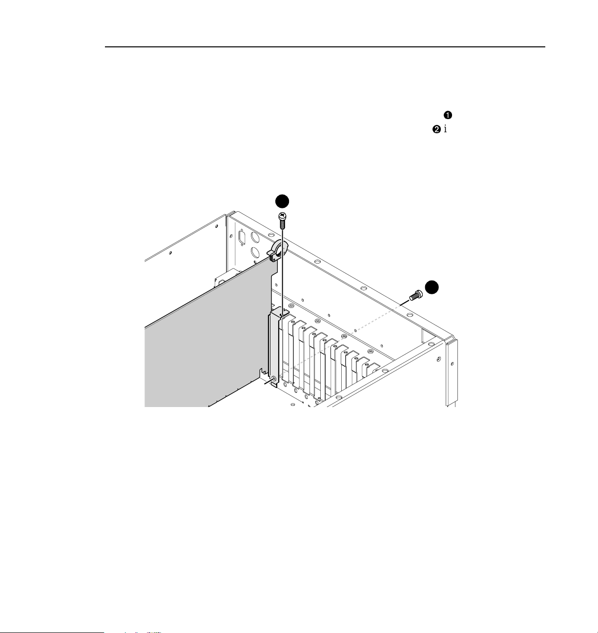
Removing the Profile Unit from the Instrument Rack
If you cannot or do not want to install MPEG boards with the Profile chassis
extended on the rack slide s, use the following procedure to remove the unit f rom
the instrument rack:
1. Remove all cables connected to the rear of the Profile unit. If you have not
done so already, label all cable s before removing them to make it easier to
reconnect them later.
2. Loosen the front-panel r etaining screw (
3. Grasp the handles and pull the chassis out (
latch. This holds the Profile chassis firmly in position.
WARNING: To avoid personal injury, at least two people must remove the
!
Profile chassis from the rack—it is too heavy for one person to lift.
4. With a person on each side of the unit, pre ss in both track stop latch buttons
(
in Figure 1) and carefully slide the Profile chassis free of the tracks (Í in
Ì
Figure 1).
5. Place the Pro f ile u nit on an ESD -p rot ect e d wo rk surface.
NOTE: No w is probably a good time to clean the front filter of your Profile
unit. With a strong vacuum, y ou can clean the filter through the front cover.
in Figure 1).
Ê
in Figure 1) until the slides
Ë
6 MPEG Board Upgrade Installat ion
Page 17

4
3
Stop latch button
(each side)
Removing the Profile Unit from the Instrument Rack
1
2
0169-2
Figure 1. Removing the Profi le unit from the instrument rack
MPEG Board Upgrade Installat ion 7
Page 18

MPEG Board Upgrade Installation
Removing the Chassis Covers
To remove the chassis covers f rom the Profile unit:
NOTE: The front cha ssis cov er must be removed first because it ov er laps the
rear cover.
1. Turn Profile system power off and remove the power cord .
2. Loosen the fr ont pa nel r etaining sc rew and pull the cha ssis out f rom the rack
until the slide secti ons latch. If the rack is not anchored firmly, remove the
chassis from the rack (see the instructions under “Removing the Profile Unit
from the Instrument Rack” on page 6).
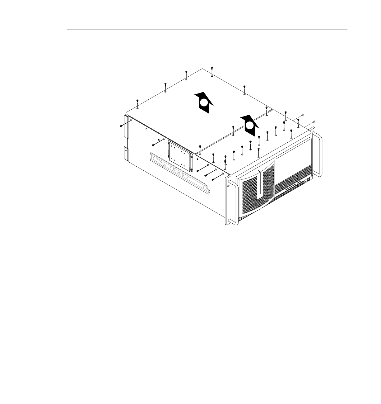
3. Use the Torx tool with the T10 tip to remove the top screws from the front
chassis cover (
round-headedside screws. Set the cover aside.
NOTE: Store the chassis screws in a container so that you do not lose them.
They must all be reinstalled as they are require d to meet the EMI
specificati ons for the disk recorder.
in Figure 2) and use the T15 tip to remove the
Ê
4. Use the Torx tool with the T10 tip to remove the rear chassis cover (
Figure 2). Set the cover aside.
8 MPEG Board Upgrade Installat ion
Ë
in
Page 19
9675-9
Removing the Chassis Covers
2
1
Figure 2. Removing the front and rear chassis covers
MPEG Board Upgrade Installat ion 9
Page 20

MPEG Board Upgrade Installation
Removing the Circuit Board Hold-down Brackets
There are two hold-down brackets loc a ted in the circuit board area of the chassis
that must be removed in order to install other boards.
To remove the board hold-down brackets:
1. Use the Torx tool with the T10 tip to remove the exterio r scr ew (
Figure 2) that secures the rear board hold-down bracket.
Ê
in
2. Lift the bracket (
3. Use the Torx tool with the T10 tip to remove the interior scre w (
Figure 2) that secures the front board hold-down bracket.
4. Lift the bracket (Í in Figure 2) up and out of the chassis and set it aside.
in Figure 2) up and out of the chassis and set it aside.
Ë
Ì
in
10 MPEG Board Upgrade Installat ion
Page 21

Removing the Circuit Board Hold-down Brackets
3
4
1
2
9675-2
Figure 3. Removing the circuit board hold-down brackets
NOTE: Now would be a good time to do the memory upgrades mentioned in
“Master and Slave EDR Memory Requirements” on page 3.
MPEG Board Upgrade Installat ion 11
Page 22

MPEG Board Upgrade Installation
Installing Boards in an Option MG Unit
To install one or two MPEG boards in an MPEG-ready PDR200 (Option MG with
serial number B030000 or above):
1. Remove the three-slotte d PCI Inte rconnect board and remove all cables
connected Profile boards, such as SCSI, Sharcnet, or audio clock cables
(look at Figure 7 on page 23 if you need help identifying the Shar cnet and
audio clock cable s). Label each cable befor e removing it and draw a sim ple
diagram to make it easier to reconnect the cabl es later. Remove any cable tie
wraps, if necessary.
CAUTION: Be certain to labe l the SCSI cables before removin g them s o that
!
!
you can reconnect them properly. If the A and C SCSI cables are reversed,
the file system will be corrupted.
2. Remove the slot cover for slot J8. If you are installing two MPEG boards,
also remove the slot cover for J12.
CAUTION: Forcing the board into the slot may result in bent connect ors on
!
!
the mother board. Carefully follow the instructions in step 3 to avoid
damaging hardware.
3. Install an encoder board (P2MPG12) in slot J8 and a decoder board
(P2MPG04) in J12. If you are installing two encoder boards or two decoder
boards, slot order doesn’t matter. To install the boards correctly:
- Align the board with the connectors on the motherboard. Make sure that
the board is in the board guide at the front edge.
- With the extractor on the front end of the board in the up position, press
down on the board firmly until it is seated.
- As you push the b oard i nto the conne ctors, yo u will feel the boa rd enga ge
first one, then another set of contacts in the connector. The board is
properly seate d when the top of the r ear mounting br acket is re sting on t he
rear chassis wall shelf.
12 MPEG Board Upgrade Installat ion
Page 23
Installing Boards in an Option MG Unit
4. Install the slot c over scre ws. Use the Torx tool with the T15 t ip to inst all the
mounting screws in the top o f the slot cover insid e thechassis(
and through the rear panel at the bottom of the slot cover (
in Figure 4)
Ê
in Figure 4).
Ë
1
2
Figure 4. Screw locati ons for board mounting sl ot cover
MPEG Board Upgrade Installat ion 13
9040-13
Page 24
MPEG Board Upgrade Installation
5. Connect the SCSI cables, as shown in Figure 5.
6. Install the five-slotted PCI Interconnect board. This board is a high-speed
bus used to move data be tween boards with PCI connectors. Align the center
keys on the PCI I nterconnect board wi th the keys on the Master EDR board
in slot J10. Using appropriate pressure, press down firmly on the
interconnect board to en sure that it is properly seated (see Figure 6).
SCSI D
SCSI B
Master EDR Board
Slave EDR Board
Figure 5. Reconnect the SCSI cables
14 MPEG Board Upgrade Installat ion
SCSI A
SCSI C
0169-6
Page 25

Installing Boards in an Option MG Unit
7. Connect the audio clock and Sharcnet c ables according to the diagram you
drew earlier or see “Audio Clock and Sharcnet Cabling” on page 21.
8. If you plan to install additiona l video I/O or audio boards, do so now using
the instructions pr ovided with each field installation kit.
9. Follow the reassembly instructions under the heading “Reassembling the
Profile Cha ssis ” on page 28.
WARNING: To avoid personal injury from electri cal shock and/or damage to
!
!
disk drives, do not apply power until all covers are in place and secured.
PCI Interconnect
Board
MPEG Board
Fibre Channel Board
Master EDR Board
Slave EDR Board
MPEG Board
Alignment Keys
Figure 6. Installing the five-slotted PCI Inter connect board
0169-1
MPEG Board Upgrade Installat ion 15
Page 26

MPEG Board Upgrade Installation
Installing Boards in a non-Option MG Unit
A non-Option MG PDR200 (with serial number B030000 or above) already has
the Master a nd Slave EDR boards in the corre ct slots (see Ta ble 3 on page 5), but
it is possible that you have analo g composite or serial digital component I/O
boards installe d in slots J8 or J12. These boar ds must be removed and installe d in
other slots in order to install MPEG boards.
To install MPEG boards in a non-Option MG PDR200:
1. Remove the three-slotte d PCI Inte rconnect board and remove all cables
connected t o Prof ile b oard s , su ch as SC SI, Sharcnet, or audio clock cab les
(look at Figure 7 on page 23 if you need help identifying the Shar cnet and
audio clock cable s). Label each cable befor e removing it and draw a sim ple
diagram to make it easier to reconnect the cabl es later. Remove any cable tie
wraps, if necessary.
CAUTION: Be certain to labe l the SCSI cables before removin g them s o that
!
!
you can reconnect them properly. If the A and C SCSI cables are reversed,
the file system will be corrupted.
2. If there a re analog co mposite or ser ial digita l component I/O boards i nstalled
in slots J8 or J12, remove the boards. For complete instruc tions on removing
circuit boards, see “Removing Circuit Boards” on page 18.
CAUTION: Forcing the board into the slot may result in bent connect ors on
!
!
the mother board. Carefully follow the instructions in step 3 to avoid
damaging hardware.
3. Install the MPEG boards . An encoder boar d (P2MPG12) should go in slot J8
and a decoder board (P2MPG04) in J12. If you are instal ling two encoder
boards or two de coder boards, slot order doesn’t matter . To instal l the boards
correctly:
16 MPEG Board Upgrade Installat ion
Page 27

Installing Boards in a non-Option MG Unit
- Align the board with the connectors on the motherboard. Make sure that
the board is in the board guide at the front edge.
- With the extractor on the front end of the board in the up position, press
down on the board firmly until it is seated.
- As you push the bo ard i nto the connecto rs, yo u will feel the boa rd enga ge
first one, then another set of contacts in the connector. The board is
properly seate d when the top o f the r ear mounting br acket is re sting on t he
rear chassis wall shelf.
4. Reinstall any video I/O or audio boards that you had to move out to make
room for the MPEG boards. (For information of appropriate slots for video
and audio boards, see Table 7 on page 34.)
5. Install the slot c over scre ws. Use the Torx tool with the T15 t ip to inst all the
mounting scre ws in the top of the slot cove r ins ide thechassis (
on page 13) and through the rear panel at the bottom of the slot cover (
Figure 4 on page 13).
6. Connect the SCSI cables, as shown in Figure 5 on page 14.
7. Install the five-slotted PCI Interconnect board. This board is a high-speed
bus used to move data be tween boards with PCI connectors. Align the center
keys on the PCI I nterconnect board wit h the keys on the Master EDR board
in slot J10. Using appropriate pressure, press down firmly on the
interconnect board to en sure that it is properly seated (see Figure 6 on
page 15).
8. Connect the audio clock and Sharcnet c ables according to the diagram you
drew earlier or see “Audio Clock and Sharcnet Cabling” on page 21.
9. Follow the reassembly instructions under the heading “Reassembling the
Profile Cha ssis ” on page 28.
in Figure 4
Ê
Ë
in
WARNING: To avoid personal injury from electri cal shock and/or damage to
!
!
disk drives, do not apply power until all covers are in place and secured.
MPEG Board Upgrade Installat ion 17
Page 28

MPEG Board Upgrade Installation
Installing Boards in an Early PDR200 Unit
If you have an early PDR200 (serial number B029999 or below), you can install
MPEG boards by following this procedure . I t may be necessa ry to remove some
or all of the boards in slots J5 through J15 in or der to follow the recommendati ons
for MPEG installation. In doing so, you may lose some slots otherwise used for
video I/O boards . To reinstal l EDR and Fibre cha nnel boards, fol low the sl ot order
shown in Table 3 on pa ge 5. Tabl e 3 a lso s hows wh ere th e MPEG boards must go.
For further guidance on board placement, refer to Table 7 on page 34. Follow the
instructions under “Selecting a Board L ocat i on ” on page 36. Also, it will be
helpful to make a copy of Table 8 on page 35 to chart the placement of boards in
their proper slots.
NOTE: If you decide to keep the chassis in the rack during the installation, it
is a good idea to loosen any screws that n eed to be remove d from the back of
the Profile unit before sliding it forward on the racks.
Removi ng Circuit Boards
Use the following procedure to remove one or more circuit boards—as many as
necessary—from the motherboard, in order to make room insta lling MPEG
boards:
1. Remove all cables connected to the rear of the Profile unit. If you have not
done so already, label each cable before removing it and draw a simple
diagram to make it easier to reconnect the cabl es later. Remove any cable tie
wraps, if necessary.
2. Remove the three-slotte d PCI Inte rconnect board and remove all cables
connected t o Prof ile b oard s , su ch as SC SI, Sharcnet, or audio clock cab les
(look at Figure 7 on page 23 if you need help identifying the Shar cnet and
audio clock cable s). Label each cable befor e removing it and draw a sim ple
diagram to make it easier to reconnect the cables later.
CAUTION: Be certain to labe l the SCSI cables before removin g them s o that
!
!
you can reconnect them properly. If the A and C SCSI cables are reversed,
the file system will be corrupted.
18 MPEG Board Upgrade Installat ion
Page 29
Reinstalling the Boards
3. It may be necessary remove the top slot cover screw that mounts any
adjacent circuit boards to al low more give so board removal is easier (re fer
to Figure 4 on page 13 for the location of the top screw). Use the Torx tool
with the T15 tip to do so.
4. Use the Torx tool with the T15 tip to remove the screws from the top of the
slot cover inside the chassis (
the slot cover through the rear panel outside the chassis (
CAUTION: To avoid damage to the circuit board when removing or
!
!
installing it:
- Do not rock the circuit board from side to side in the EISA bus
connector — pull straight up to remove.
- Do not grasp or push on the rear-panel connectors when removing or
installing circuit boards in the card slots.
5. Extract the circuit board:
- If the circuit board is tal l, use the extractio n lever on the front of the board
and the extractio n ring at the back of the board to lift the circuit board free
of the connectors on the motherboard.
- For shorter cir cuit boa rds, carefu lly grasp the board and lift upwa rd to f ree
the circuit board from the motherboa rd connectors. You might need to
remove an adjacent tall board to get enough room for a safe hold on the
shorter board.
in Figure 4) and the screw through bottom of
Ê
Ë
in Figure 4).
6. You may also need to remove slot covers for empty slots to prepare for the
installation of new or moved boards. If this is necessary, refer to step 4.
7. Place removed boards in the supplied antistatic bags. Fold the bags over to
protect the boards from any ESD exposure .
Reinstalling the Boards
Now that you have removed the boards from the chassis, you a re ready to reinstall
them, along with MPEG boards. See Table 3 on page 5 for placement of EDR,
Fibre Channel , and MPEG boards. For information on placing other boards, refer
to Table 7 on page 34.
CAUTION: Forcing a board into the slot m ay result in bent connectors on the
!
!
mother board. Carefully follow the instructions in step 1 to avoid damaging
hardware.
MPEG Board Upgrade Installat ion 19
Page 30

MPEG Board Upgrade Installation
1. Install the MPEG boards . An encoder boar d (P2MPG12) should go in slot J8
and a decoder board (P2MPG04) in J12. If you are instal ling two encoder
boards or two decoder boards, slot order doesn’t matter. Also, reinsta ll the
video I/O and audio boards that you had to move out to make room for the
MPEG boards. To install the boards correc tly:
- Align the boards with the connectors on the motherboard. Make sure the
board is in the board guide at the front edge.
- With the extractor on the front end of the board in the up position, press
down on the board firmly until it is seated.
- As you push the b oard i nto the conne ctors, yo u will feel the boa rd enga ge
first one, then a second set of contacts in the connector. The board is
properly seate d when the top of the r ear mounting br acket is re sting on t he
rear chassis wall shelf.
2. Install the slot c over scre ws. Use the Torx tool with the T15 t ip to ins tall the
mounting screws i n the top of the slot cover ins idethechassis (
on page 13) and through the rear panel at the bottom of the slot cover (
Figure 4).
3. Connect the SCSI cables, as shown in Figure 5 on page 14.
in Figure 4
Ê
Ë
in
4. Install the five-slotted PCI Interconnect board. This board is a high-speed
bus used to move data be tween boards with PCI connectors. Align the center
keys on the PCI I nterconnect board wi th the keys on the Master EDR board
in slot J10. Using appropriate pressure, press down firmly on the
interconnect board to en sure that it is properly seated (see Figure 6 on
page 15).
5. Connect the audio clock and Sharcnet c ables according to the diagram you
drew earlier or see “Audio Clock and Sharcnet Cabling” on page 21.
6. Follow the reassembly instructions under the heading “Reassembling the
Profile Cha ssis ” on page 28.
WARNING: To avoid personal injury from electri cal shock and/or damage to
!
!
disk drives, do not apply power until all covers are in place and secured.
20 MPEG Board Upgrade Installat ion
Page 31

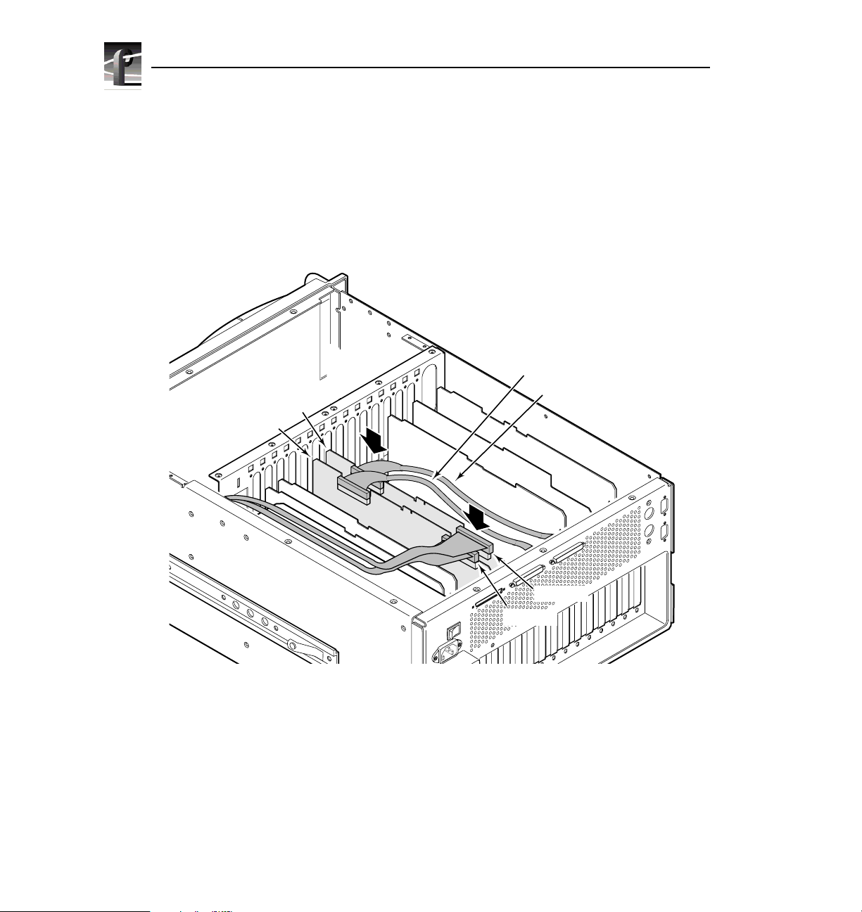
Audio Clock and Sharcnet Cabling
Audio Clock and Sharcnet Cabling
This section explains how to connect Sharcnet and audio clock cables between
Audio Signal Processing Boards (ASPB) and video I/O boards. Each ASPB has
four Sharcnet connec tors for embedded di gital audio, two S harcnet connectors f or
interconnection with another ASPB, four audio record clock connectors and two
reference clock inpu t connec tors. Serial digital I/O boar ds have two Sharcnet
connectors for input and output of embedded audio, and two record clock output
connectors. Analog composite I/O boards only have two record clock output
connectors, as they do not support embedded audio.
General Sharcnet Rules
Serial digi tal I/O boa rds extra ct embedded audi o, route it to the ASPB, and r eceive
audio output from the ASPB to be embedded in the serial digital stream.
Beginning with the ASPB in the lowest numbered slot, the fourth Sharcnet
connector from the rear panel is connected to the first Sharcnet connector (also
from the rear) on the serial digit al I/O board in the lowest numbered slot . Next, the
sixth connector from the rear on the ASPB is connected to the second connector
on the serial digital I/ O board.
If you have a second serial digital I/O board, the third connector on the ASPB is
connected to the first conn ector on the second serial digital I/O board; the n, the
fifth to the second. See an example of Sharcnet cabling for one serial digital I/O
board in Figure 7, for two boards in Figure 8, and for four boards in Figure 9.
NOTE: The Sharcnet conn ectors on the MPEG boards are not used at this
time.
General Audio Clock Rules
On an ASPB, there is one au d io rec o rd clock inpu t connection for each ban k of
four audio channels, so that ther e are four record clock input connectors fo r the
sixteen audio channels on an ASPB.The first input record clock connector, for the
first bank (channels 1 thr ough 4), is the one closest to the rear of the chassis, and
the next three c onnectors follo w the sequence f or banks 2, 3, and 4. The re maining
two connectors are not used.
MPEG Board Upgrade Installat ion 21
Page 32

MPEG Board Upgrade Installation
In general, the video board in the lowest-numbered slot must provide the audio
clock signal to the to the first audio bank (and the second bank if the vide o board
has two inputs) on the ASPB. The video I/O board installed in the next
higher-numbered slot should provide the audio record clock signals for the next
audio banks, and so on until all four audio banks have their record clocks
connected.
For example, if you have two anal og composite I/O video boards in slots J14 and
J15, the audio clock signal from the board in J14 should be connected to the first
and second audio record input cloc k signals on the ASPB while the signals from
J15 should be connected to the third and fourth co nnectors. See serial digital I/O
examples of audio clock cabli ng for one ser ial digital I/O board in Figure 7 on
page 23, for two boa rds in Figure 8 on page 25, and for four b oards in Figure 9 on
page 27.
If your Profile unit only has one ASPB, you can connect only four record clocks
to it. If your disk recorder has two ASPBs, eight record clocks are available. If
your Profile unit has more than four video inp uts, you should connect record
clocks from video inputs that mig ht record video that is not genlocked to your
house referenc e, such as remot e feeds fr om outside your facility. Any video inputs
that are not supplying a record clock to the ASPB should be locked to your house
reference, if audio is to be associated with those inputs. Otherwise, audio clock
errors could occur during r ecor ding.
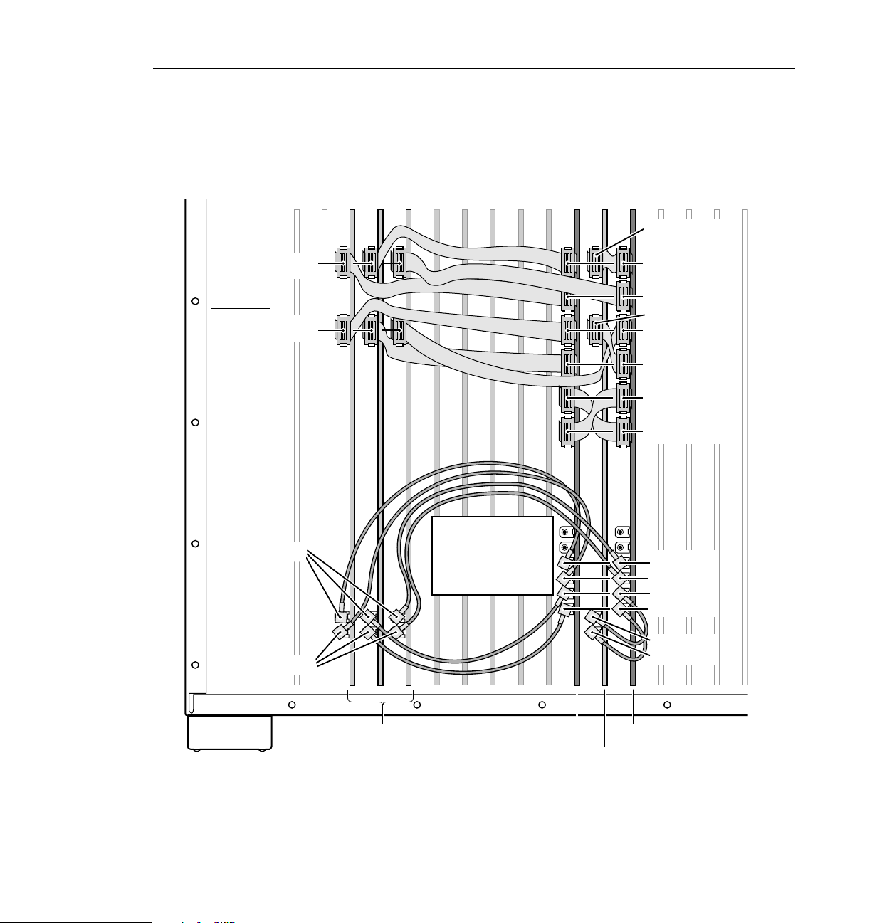
The first cabli ng example shows the ex t ernal aud io cl ock an d Sha rcn et cab l ing
necessary f or a single serial digital I/O board us ed with a single ASPB. The cable
connections are list ed in Table 4 and shown in Figure 7.
Table 4. Cabling for a serial digital I/O board and an ASPB
Cable Type From Serial
Sharcnet Sharcnet In Sharcnet Out 1
Sharcnet Sharcnet Out Sharcnet In 1
Audio clock Channel A Audio 1
Audio clock Channel B Audio 2
22 MPEG Board Upgrade Installat ion
To ASPB
Digital I/O
Page 33

General Audio Clock Rules
J17 J13J16
Sharcnet Out
J15 J14 J6J7
Sharcnet In
Channel B
J11 J9
J12
MPEG
PCI Interconnect Bd.
J10
Slave EDR
Master EDR
(Do not place cabling
on top of board.)
J8
J4 J3 J2
J5
Sharcnet Out 1
Sharcnet Out 2
Sharcnet In 2
Sharcnet In 1
Sharcnet
Expansion 1
Sharcnet
Expansion 2
Audio 4
Audio 3
Audio 2
Audio 1
J1
Channel A
Serial
Digital I/O
Figure 7. Cabling for a serial digital I/O board and an ASPB
MPEG Board Upgrade Installat ion 23
ASPB
0169-3
Page 34

MPEG Board Upgrade Installation
The second cabling e xample sho ws the exte rnal audi o clock and Shar cnet cablin g
necessary for two serial digital I/O boards used with an ASPB. The connections
are listed in Table 5 and shown in F igure 8.
Tabl e 5. Cabling for two serial digital I/O boards and an ASPB
Cable Type Serial Digital
I/O Slot
Sharcnet J14 Sharcnet In Sharcnet Out 1
Sharcnet J15 Sharcnet In Sharcnet Out 2
Sharcnet J14 Sharcnet Out Sharcnet In 1
Sharcnet J15 Sharcnet Out Sharcnet In 2
Audio clock J14 Channel A Audio 1
Audio clock J14 Channel B Audio 2
Audio clock J15 Channel A Audio 3
Audio clock J15 Channel B Audio 4
From Serial
Digital I/O
To ASPB
24 MPEG Board Upgrade Installat ion
Page 35

General Audio Clock Rules
J17 J13J16
Sharcnet In
Sharcnet Out
Channel B
J11 J9
J15 J14 J6J7
J12
MPEG
PCI Interconnect Bd.
J10
Slave EDR
(Do not place cabling
on top of board.)
Fibre Channel
Master EDR
J8
MPEG
J4 J3 J2
J5
Sharcnet Out 1
Sharcnet Out 2
Sharcnet In 2
Sharcnet In 1
Sharcnet
Expansion 1
Sharcnet
Expansion 2
Audio 4
Audio 3
Audio 2
Audio 1
J1
Channel A
Serial
Digital I/O
Figure 8. Cabling for two seri al digital I/O boards and an ASPB
ASPB
MPEG Board Upgrade Installat ion 25
0169-4
Page 36
MPEG Board Upgrade Installation
This final cabling example shows the external audio clock and Sharcnet cabling
for four ser ial di gital I/O boa rds use d with two ASPBs. The c onnection s a re liste d
in Table 6 and shown in Figure 9.
Tabl e 6. Cabling for four serial digital I/O boards and two ASPBs
Cable Type Serial Digital
I/O Slot
Sharcnet N/A N/A Sharcnet
Sharcnet N/A N/A Sharcnet
Sharcnet J6 Sharcnet In Sharcnet Out 1 N/A
Sharcnet J6 Sharcnet Out Sharcnet In 1 N/A
Sharcnet J13 Sharcnet In Sharcnet Out 2 N/A
Sharcnet J13 Sharcnet Out Sharcnet In 2 N/A
Sharcnet J14 Sharcnet In N/A Sharcnet Out 1
Sharcnet J14 Sharcnet Out N/A Sharcnet In 1
Sharcnet J15 Sharcnet In N/A Sharcnet Out 2
Sharcnet J15 Sharcnet Out N/A Sharcnet In 2
Audio clock J6 Channel A Audio 1 N/A
Audio clock J6 Channel B Audio 2 N/A
Audio clock J13 Channel A Audio 3 N/A
Serial Dig ital I/O ASPB 1 (J 5) ASPB 2 (J7)
Sharcnet
Expansion 2
Expansion 1
Expansion 1
Sharcnet
Expansion 2
Audio clock J13 Channel B Audi o 4 N/A
Audio clock J14 Channel A N/A Audio 1
Audio clock J14 Channel B N/A Audio 2
Audio clock J15 Channel A N/A Audio 3
Audio clock J15 Channel B N/A Audio 4
26 MPEG Board Upgrade Installat ion
Page 37
General Audio Clock Rules
J17 J13J16
Sharcnet In
Sharcnet Out
Channel B
J11 J9
J15 J14 J6J7
J12
MPEG
PCI Interconnect Bd.
J10
Slave EDR
(Do not place cabling
on top of board.)
Fibre Channel
Master EDR
J8
MPEG
J4 J3 J2
J5
Sharcnet In
Sharcnet Out 1
Sharcnet Out 2
Sharcnet Out
Sharcnet In 2
Sharcnet In 1
Sharcnet
Expansion 1
Sharcnet
Expansion 2
Audio 4
Audio 3
Audio 2
Audio 1
J1
Channel A
Channel B
Channel A
Serial
Digital I/O
Figure 9. Cabling for four serial digital I/ O boards and two ASPBs
ASPB2 ASPB1
Serial
Digital I/O
MPEG Board Upgrade Installat ion 27
0169-5
Page 38

MPEG Board Upgrade Installation
Reassembling the Profile Chassis
To reassemble the Profile chassis:
1. Apply stick-on labe ls on the Profile chassi s rear panel to help identif y all new
board locations (see Fig ure 10).
2. Bundle any loose cables with the tie wraps pr ovided.
3. Use the Torx tool with the T10 tip to reinstall the rear board hold-down
bracket (see Figure 3 on page 11). Make sure that boards in the chassis fit
into the grooves in the bracket .
CAUTION: To prevent damage to an Analog Composite Monitor board, do
!
!
not install a short board extensi on on the front hold-down bracket at the
Monitor board location.
4. If necessary, move or remove any sh ort board extensions on the front boa rd
hold-down bracket. Then use the Torx tool with the T10 tip to reinstall the
bracket (see Figure 3).
5. Use the Torx tool with the T10 tip to r einsta ll the re ar chassis c over wit h the
screws previously removed.
NOTE: When reinstalling rear and front chassis covers, start all the screws
before tighteni ng them. Th is ensures that the screw threads are properly
aligned, and will help avoid stripping threads or breaking screws.
6. Use the Torx tool with the T10 and T15 tips to reinstall the front chassis
cover with the screws previously removed.
7. Reinstall the Profile chassis in the rack and reconnect as labeled a ll external
cables previously removed.
8. Apply power to the Profile system and check the presence of the MPEG
boards with the procedure under “Installation Verification” on page 29.
28 MPEG Board Upgrade Installat ion
Page 39

Figure 10. Stick-on label location
Installation Verification
Verification for installation of the MPEG board consists of:
• Checking the Profile L og f or mess ages about t he pr esence of MPEG boa rds.
On the Windows NT 4.0 d esktop, double- click the
Start | Programs | PDR Applications | Pro fi le Log.
Installation Verification
9676-26
Labels
Profile Log icon or choose
• Using Configuration Manager to see if the system recognizes the newly
installed boards . For instructions, see “Using Configurat ion Manager to
Verify Boar ds ” on page 30.
• Using VdrPanel to verify that you can configure MPEG video and audio
resources, and then record and play on all available channels . This will help
detect any problems with the MPEG boards for video an d/or Sharcnet
cabling for audio. For information on configuring VdrPanel, as well as
recording and playing clips, see the chapter on VdrPanel in the Profile
Family User Manual.
• Using Media Manager to convert media with the Transcode Utility and to
perform media transfers over Fibre Channel, if a Fibre Channel board is
installed. For information on the Transcode Utility and copying or moving
media over Fibre Channel, see the chapter on Media Manager in the Profile
Family User Manual.
MPEG Board Upgrade Installat ion 29
Page 40

MPEG Board Upgrade Installation
Using Configura tion Mana ger to Verify Boards
You can use the Configuration Manager to verify the presence of MPEG encoder
and decoder boards. Look at the bottom of the Configu ration Manag er window to
ensure that the abbreviation MPEG appears in the slots where they were installed
(J8 and J12). Both encoder and decoder boards appear at the bottom of the
window. See Fi g ure 11 for an example.
Also, you should be able to see the decoder MPEG host boards listed in the
configuration tree. Encoder boards do not appear in the configuration tr ee since
there is no need to configure them with software.
If you have MPEG decoder boards installed in your Profile, you need to obtain a
timing signal from a video I/O board to synchr onize your output. See the
instructions on setting MPEG input timing in the chapter on Configuration
Manager in the Profile Family User Manual.
To check for recognition of added MPEG boards in a PDR200:
1. From the Windows NT 4.0 desktop, open the Configurat ion Manager
window by choosing
Manager
.
2. Check the configuratio n tree and the bottom of the window for the presenc e
of MPEG boards.
Start | Programs | PDR Applications | Configuration
3. Choose
30 MPEG Board Upgrade Installat ion
File | Exit.
Page 41

Using Configuration Manager to Verify Boards
MPEG Boards
Figure 11. Configuration Manager showing MPEG boards
MPEG Board Upgrade Installat ion 31
Page 42

MPEG Board Upgrade Installation
Board Location Guide
This board location guide is pro vided to help you install an MPEG board in a
PDR200 Video File Server that is not an Option MG, that is, not shipped from the
factory as MPEG ready. The board layout for an Option MG PDR200 eases
MPEG board installation, but other systems may require that you move existing
boards to accommodate the MPEG board. This guide will help you do that.
If you move any circuit boar ds, remember that some boards must oc cupy specific
slots, while others can be installed in almost any slot as long as their I/O
requirements ar e met (see Tabl e 7 on page 34). The board loc ation guide identifies
the video router inputs and outp uts of each Profile board currently available, as
well as the input and output connections on the video router connectors on the
motherboard.
This guide provides a general approach to board location. It explains the
relationship between the motherboard and video router connectors and provides
tables, charts and examples to as sist you in installing boards.
Video Router to Motherboard Relati onship
The video router provides and contr ols video data to twelve connectors on the
motherboard. These video dat a connectors are align ed with the main motherboard
connectors for s lots J5 through J16. Since the Referenc e Genlock (Ref Gen) boar d
must occupy J16 to pro vide the nece ssary syste m clocks, thi s discussi on excl udes
J16.
When choosing a slot for a board, the major constraint for a slot is how the board
connects to the video router . Not all boards require the same number of video I/O
connections, and not all video data connectors provi de the same number of vi deo
I/O connections. Therefore, you must know how many input and output
connections the board need s, if any, and the slots available that meet those needs.
Table 7 on page 34 lists each of the boards which may be installed in the Profile
system and the recommended slots, possi ble alternatives, and restrictions f or each
board. If more than one slot is recommended or possible for a board, those slots
are listed in the order of preference.
32 MPEG Board Upgrade Installat ion
Page 43

Video Router I/O Connections
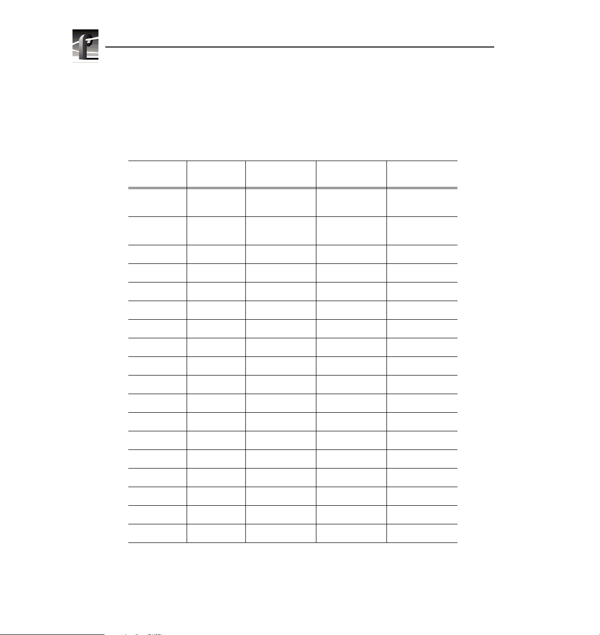
Now let’s look at the video router connections a vailable at slo ts J5–J15. Table 8 is
a blank board location chart tha t shows the video router input and output
connections. In this table:
Video Router I/O Connections
• The
Slot column lists each slot on the motherboard connected to the video
router.
• The
Board column is where you write the boards currentl y insta lled and the
name of the board you want to install.
• The
Input column identifies input connections available to the installed
boards from the video router. The numbers in the blocks correspond to the
order input connections are assigned at the video router connector.
• The
Output column identifies output connections available from the
installed boar ds to the video rou ter. The numbers in t he blocks corre spond to
the order output connections are assigned at the video router connect or.
• The shaded blocks in the diagram indicate video router connections shared
between slots. A shar ed connec tion is avail abl e to eithe r slot, but not both at
the same time. For instance:
- The shaded blocks between slots J5 and J6, slots J7 and J8, slots J10 and
J11, and slots J12 and J13 indicate shared input connections.
- The shaded blocks between slots J8 and J9, slots J10 a nd J11, a nd slots
J12 and J13 indicate shared output connections.
MPEG Board Upgrade Installat ion 33
Page 44

MPEG Board Upgrade Installation
Table 7. Board I/O requir em ents and restrictions for an MPEG-ready PDR200
Board Video Router
Connection
Requirements
Inputs Outputs
CPU n/a n/a J1 None Reserve d for PC car d only
VGA n/a n/a J2 None ISA only
LAN n/a n/a J3 None EISA only
SCSI n/a n /a J4 None EISA only
RefGen n/a n/a J16 None Reference genlock
RS-422 n/a n/a J17 None EISA only
Master E DR 2 2 J10 None Must be adjacent to Slave EDR and Fibre
Slave EDR 2 2 J11 None Must be adjacent to Master EDR and
Analog
Compos ite In
Analog
Composite
Decoder
Four Ch annel
Analog Out
Analog
Compos ite I/O
Analog
Composite
Monitor Out
Serial Digital I/O 2 2 J14, J15 J6, J7, J13 Cables must be able to reach ASPBs
CAV In None 1 J6 J7, J13,
MPEG encoder 1 2 J8, J12 None Must be adjacent to eithe r Slave EDR or
MPEG decoder None 4 J12, J8 None Must be adjacent to either Slave EDR or
Fibre Channel None None J9 None Must be adjacent to Master EDR. PCI
Mix Effe cts 6 2 J6 J7 Only J6 and J7 have 5 inputs; board m ust
Audio Signal
Processing
Board (ASPB)
None 1 J14 J15, J7 Must be ad ja cent to the An alog C ompos it e
None None J13 J14, J6 Must be adjacent to Analog Composite In
4 None J6 J7
2 2 J14, J15 J6, J7, J13
4 None J6 J7
None None J5 (1st)
Recommended
Slots
J7 (2nd)
Other
Possible
Slots
J14, J15
J6, J13,
J14, J15
Comments
Channel (if installed). PCI Interconnect
required.
MPEG (if installed). PCI Interconnect
required.
Decoder
Fibre Ch an ne l ( if in st a ll ed ) . P CI
Interconnect required.
Fibre Ch an ne l ( if in st a ll ed ) . P CI
Interconnect required.
Interconnect required.
be able to g et a s har ed i np ut (t he 6t h) f rom
an adja cent slot (J5 or J8)
Cables mus t be abl e to rea ch vide o board s
or additional ASPB. Second ASPB
necessa ry for 32 channels of audio.
34 MPEG Board Upgrade Installat ion
Page 45

Video Router I/O Connections
Table 8. Board location chart
Slot Board Input Output
J5
1
23
J6
J7 1 1
2
3
42
5
6
J8
J9 1
22
J10 1 1
2 34
J11
J12 1 1
22
3
4 34
J13
J14 1 1
23
J15 1 1
23
1
2
62
5
4
31
2
1
21
12
34
43
2
4 43
32
2
11
2 43
12
2
2
1
1
MPEG Board Upgrade Installat ion 35
Page 46

MPEG Board Upgrade Installation
Selecting a Board Location
Here’s how to use the tables to select a location for a board. Make a copy of
Table 8 to use as a template for recording information for board placement.
1. Write the board name in Table 8 and, referring to Table 7, put a check mark
3
) in each input and output block used by each board currently installed in
(
your Profile system. Start with the 1 block for each board.
2. Look in Table 7 to see the input and output requirements and both the
recommended slot and alternative slots for the board you want to install.
3. Look in Table 7 for a slot with the required video router connections
available. Starting with the 1 block, put a n 8 in each block that corresponds
to an input and output requirement for the newly added board. If the
recommended slot is occupie d, or there are not enough input or output blocks
available, lo ok at the al te rnat i ve slo ts.
4. If all input and output require ments f or the board match the available ones
for the slot, write the board na me in the
the board.
NOTE: If you can’t find an open slot with the I/O connections which meets
the I/O requirements of the board you want to install, you will have to move
existing boards. You can use Table 7 and Table 8 to experiment with various
board locations before deciding on one.
Board column for the slot and install
36 MPEG Board Upgrade Installat ion
 Loading...