

Page 1
Kayak
DIGITAL PRODUCTION SWITCHER
User Manual
SOFTWARE VERSION 6.9.1
071844705
MAY 2007
Page 2

Affiliate with the N.V. KEMA in The Netherlands
CERTIFICATE
Certificate Number: 510040.001
The Quality System of:
Grass Valley, Inc.
400 Providence Mine Road
Nevada City, CA 95945
United States
15655 SW Greystone Ct.
Beaverton, OR 97006
United States
10 Presidential Way
rd
3
Floor, Suite 300
Woburn, MA 01801
United States
Nederland B.V.
4800 RP BREDA
The Netherlands
Technopole Brest Iroise
CS 73808
29238 Brest Cedex 3
France
7140 Baymeadows Way
Suite 101
Jacksonville, FL 32256
United States
Weiterstadt, Germany
Brunnenweg 9
D-64331 Weiterstadt
Germany
17 rue du Petit Albi-BP 8244
95801 Cergy Pontoise
Cergy, France
Rennes, France
Rue du Clos Courtel
Cesson-Sevigne, Cedex
France
2300 South Decker Lake Blvd.
Salt Lake City, UT 84119
United States
Including its implementation, meets the requirements of the standard:
ISO 9001:2000
Scope:
The design, manufacture and support of video hardware and software products and
related systems.
This Certificate is valid until: June 14, 2009
This Certificate is valid as of: August 30, 2006
Certified for the first time: June 14, 2000
H. Pierre Sallé
President
KEMA-Registered Quality
The method of operation for quality certification is defined in the KEMA General Terms
And Conditions For Quality And Environmental Management Systems Certifications.
Integral publication of this certificate is allowed.
KEMA-Registered Quality, Inc.
4377 County Line Road
Chalfont, PA 18914
Ph: (215)997-4519
Fax: (215)997-3809
CRT 001 073004
Accredited By:
ANAB
Page 3
Kayak
DIGITAL PRODUCTION SWITCHER
User Manual
SOFTWARE VERSION 6.9.1
071844705
MAY 2007
Page 4
Contacting Grass Valley
International
Support Centers
Local Support
Centers
(available
during normal
business hours)
France
24 x 7
Australia and New Zealand: +61 1300 721 495 Central/South America: +55 11 5509 3443
Middle East: +971 4 299 64 40 Near East and Africa: +800 8080 2020 or +33 1 48 25 20 20
Europe
+800 8080 2020 or +33 1 48 25 20 20
+800 8080 2020 or +33 1 48 25 20 20
Hong Kong, Taiwan, Korea, Macau: +852 2531 3058 Indian Subcontinent: +91 22 24933476
Asia
Southeast Asia/Malaysia: +603 7805 3884 Southeast Asia/Singapore: +65 6379 1313
China: +861 0660 159 450 Japan: +81 3 5484 6868
Belarus, Russia, Tadzikistan, Ukraine, Uzbekistan: +7 095 2580924 225 Switzerland: +41 1 487 80 02
S. Europe/Italy-Roma: +39 06 87 20 35 28 -Milan: +39 02 48 41 46 58 S. Europe/Spain: +34 91 512 03 50
Benelux/Belgium: +32 (0) 2 334 90 30 Benelux/Netherlands: +31 (0) 35 62 38 42 1 N. Europe: +45 45 96 88 70
Germany, Austria, Eastern Europe: +49 6150 104 444 UK, Ireland, Israel: +44 118 923 0499
Copyright © Grass Valley. All rights reserved.
This product may be covered by one or more U.S. and foreign patents.
United States/Canada
24 x 7
+1 800 547 8949 or +1 530 478 4148
Grass Valley Web Site
The www.thomsongrassvalley.com web site offers the following:
Online User Documentation — Current versions of product catalogs, brochures,
data sheets, ordering guides, planning guides, manuals, and release notes
in .pdf format can be downloaded.
FAQ Database — Solutions to problems and troubleshooting efforts can be
found by searching our Frequently Asked Questions (FAQ) database.
Software Downloads — Download software updates, drivers, and patches.
4 Kayak — User Manual
Page 5

Contents
Preface. . . . . . . . . . . . . . . . . . . . . . . . . . . . . . . . . . . . . . . . . . . . . . . . . . . . . . . . . . . . . . . . . . . . 17
Section 1 — System Overview. . . . . . . . . . . . . . . . . . . . . . . . . . . . . . . . . . . . . . . . . . 19
Contents
About This Manual . . . . . . . . . . . . . . . . . . . . . . . . . . . . . . . . . . . . . . . . . . . . . . . . . . . . 17
Standard Documentation Set. . . . . . . . . . . . . . . . . . . . . . . . . . . . . . . . . . . . . . . . . . 17
Other Documentation . . . . . . . . . . . . . . . . . . . . . . . . . . . . . . . . . . . . . . . . . . . . . . . . 17
Introduction . . . . . . . . . . . . . . . . . . . . . . . . . . . . . . . . . . . . . . . . . . . . . . . . . . . . . . . . . . 19
Kayak HD Switcher Models. . . . . . . . . . . . . . . . . . . . . . . . . . . . . . . . . . . . . . . . . . . 19
Kayak DD Switcher Models. . . . . . . . . . . . . . . . . . . . . . . . . . . . . . . . . . . . . . . . . . . 20
Kayak DD-1. . . . . . . . . . . . . . . . . . . . . . . . . . . . . . . . . . . . . . . . . . . . . . . . . . . . . . . 20
Kayak DD-2. . . . . . . . . . . . . . . . . . . . . . . . . . . . . . . . . . . . . . . . . . . . . . . . . . . . . . . 21
Kayak HD Standard Features . . . . . . . . . . . . . . . . . . . . . . . . . . . . . . . . . . . . . . . . . 22
Kayak HD Options . . . . . . . . . . . . . . . . . . . . . . . . . . . . . . . . . . . . . . . . . . . . . . . . . . 23
Supported Control Protocols . . . . . . . . . . . . . . . . . . . . . . . . . . . . . . . . . . . . . . . . . . 24
System Components . . . . . . . . . . . . . . . . . . . . . . . . . . . . . . . . . . . . . . . . . . . . . . . . . . . 25
Kayak Control Surfaces . . . . . . . . . . . . . . . . . . . . . . . . . . . . . . . . . . . . . . . . . . . . . . 25
1 M/E Control Panel . . . . . . . . . . . . . . . . . . . . . . . . . . . . . . . . . . . . . . . . . . . . . . . 25
1.5 and 2 M/E Control Panel . . . . . . . . . . . . . . . . . . . . . . . . . . . . . . . . . . . . . . . . 26
2.5 and 3M/E Control Panel. . . . . . . . . . . . . . . . . . . . . . . . . . . . . . . . . . . . . . . . . 27
Kayak Video Processor Frames. . . . . . . . . . . . . . . . . . . . . . . . . . . . . . . . . . . . . . . . 28
Kayak HD 4 RU Frame . . . . . . . . . . . . . . . . . . . . . . . . . . . . . . . . . . . . . . . . . . . . . 28
Kayak HD 8 RU Frame . . . . . . . . . . . . . . . . . . . . . . . . . . . . . . . . . . . . . . . . . . . . . 29
KDD-PSU Power Supply Option . . . . . . . . . . . . . . . . . . . . . . . . . . . . . . . . . . . . . . 30
Video Signal Flow . . . . . . . . . . . . . . . . . . . . . . . . . . . . . . . . . . . . . . . . . . . . . . . . . . . . . 31
Section 2 — Concepts . . . . . . . . . . . . . . . . . . . . . . . . . . . . . . . . . . . . . . . . . . . . . . . . . . . 35
Introduction . . . . . . . . . . . . . . . . . . . . . . . . . . . . . . . . . . . . . . . . . . . . . . . . . . . . . . . . . . 35
Kayak System Configuration Overview . . . . . . . . . . . . . . . . . . . . . . . . . . . . . . . . . . 35
Installation (Engineering Setups) . . . . . . . . . . . . . . . . . . . . . . . . . . . . . . . . . . . . . . . . 36
Config — Application Control . . . . . . . . . . . . . . . . . . . . . . . . . . . . . . . . . . . . . . . . 36
Personal Settings . . . . . . . . . . . . . . . . . . . . . . . . . . . . . . . . . . . . . . . . . . . . . . . . . . . . 37
Signal Routing . . . . . . . . . . . . . . . . . . . . . . . . . . . . . . . . . . . . . . . . . . . . . . . . . . . . . . . . 37
Inputs and Sources . . . . . . . . . . . . . . . . . . . . . . . . . . . . . . . . . . . . . . . . . . . . . . . . . . 37
Kayak HD . . . . . . . . . . . . . . . . . . . . . . . . . . . . . . . . . . . . . . . . . . . . . . . . . . . . . . . . 37
Kayak DD . . . . . . . . . . . . . . . . . . . . . . . . . . . . . . . . . . . . . . . . . . . . . . . . . . . . . . . . 38
Source Definition . . . . . . . . . . . . . . . . . . . . . . . . . . . . . . . . . . . . . . . . . . . . . . . . . . . . 38
Button Assignment (Source to Button Mapping) . . . . . . . . . . . . . . . . . . . . . . . . . 39
Key Memory. . . . . . . . . . . . . . . . . . . . . . . . . . . . . . . . . . . . . . . . . . . . . . . . . . . . . . . . 39
Buses and Crosspoints . . . . . . . . . . . . . . . . . . . . . . . . . . . . . . . . . . . . . . . . . . . . . . . 39
Shifted Sources. . . . . . . . . . . . . . . . . . . . . . . . . . . . . . . . . . . . . . . . . . . . . . . . . . . . . . 41
Source Scalars (HD Only). . . . . . . . . . . . . . . . . . . . . . . . . . . . . . . . . . . . . . . . . . . . . 41
Mix/Effects (M/E) Stage . . . . . . . . . . . . . . . . . . . . . . . . . . . . . . . . . . . . . . . . . . . . . . . 42
Alternate Buses and Delegation . . . . . . . . . . . . . . . . . . . . . . . . . . . . . . . . . . . . . . . 42
Utility Bus . . . . . . . . . . . . . . . . . . . . . . . . . . . . . . . . . . . . . . . . . . . . . . . . . . . . . . . . . . 43
Effects Send . . . . . . . . . . . . . . . . . . . . . . . . . . . . . . . . . . . . . . . . . . . . . . . . . . . . . . . . 43
Kayak HD Outputs . . . . . . . . . . . . . . . . . . . . . . . . . . . . . . . . . . . . . . . . . . . . . . . . . . 44
Kayak — User Manual 5
Page 6

Contents
Kayak HD AUX Busses and Output Assignments . . . . . . . . . . . . . . . . . . . . . 44
Kayak DD Outputs . . . . . . . . . . . . . . . . . . . . . . . . . . . . . . . . . . . . . . . . . . . . . . . . . . 44
Kayak DD Program and Preview Output Busses . . . . . . . . . . . . . . . . . . . . . . 44
Kayak DD Aux Busses . . . . . . . . . . . . . . . . . . . . . . . . . . . . . . . . . . . . . . . . . . . . . 44
Resource Sharing and Point Of Use. . . . . . . . . . . . . . . . . . . . . . . . . . . . . . . . . . . . . . 45
Transition. . . . . . . . . . . . . . . . . . . . . . . . . . . . . . . . . . . . . . . . . . . . . . . . . . . . . . . . . . . . 45
Cut. . . . . . . . . . . . . . . . . . . . . . . . . . . . . . . . . . . . . . . . . . . . . . . . . . . . . . . . . . . . . . . . 46
Mix . . . . . . . . . . . . . . . . . . . . . . . . . . . . . . . . . . . . . . . . . . . . . . . . . . . . . . . . . . . . . . . 46
Full Additive Mix . . . . . . . . . . . . . . . . . . . . . . . . . . . . . . . . . . . . . . . . . . . . . . . . . . . 46
Wipes . . . . . . . . . . . . . . . . . . . . . . . . . . . . . . . . . . . . . . . . . . . . . . . . . . . . . . . . . . . . . 47
Other Wipe Pattern Generator Uses . . . . . . . . . . . . . . . . . . . . . . . . . . . . . . . . . . . 47
Preset Black . . . . . . . . . . . . . . . . . . . . . . . . . . . . . . . . . . . . . . . . . . . . . . . . . . . . . . . . 47
Fade to Black . . . . . . . . . . . . . . . . . . . . . . . . . . . . . . . . . . . . . . . . . . . . . . . . . . . . . . . 47
Transition Rate . . . . . . . . . . . . . . . . . . . . . . . . . . . . . . . . . . . . . . . . . . . . . . . . . . . . . 48
Flip Flop Background Buses . . . . . . . . . . . . . . . . . . . . . . . . . . . . . . . . . . . . . . . . . . 48
Look Ahead Preview . . . . . . . . . . . . . . . . . . . . . . . . . . . . . . . . . . . . . . . . . . . . . . . . 48
Current and Next Stack . . . . . . . . . . . . . . . . . . . . . . . . . . . . . . . . . . . . . . . . . . . . . . 48
Key Priority and Transitions. . . . . . . . . . . . . . . . . . . . . . . . . . . . . . . . . . . . . . . . . . 49
Half M/E and DSK Option . . . . . . . . . . . . . . . . . . . . . . . . . . . . . . . . . . . . . . . . . . . 49
Keying . . . . . . . . . . . . . . . . . . . . . . . . . . . . . . . . . . . . . . . . . . . . . . . . . . . . . . . . . . . . . . 49
Matte Fill Key Example . . . . . . . . . . . . . . . . . . . . . . . . . . . . . . . . . . . . . . . . . . . . . . 50
Shaping Video . . . . . . . . . . . . . . . . . . . . . . . . . . . . . . . . . . . . . . . . . . . . . . . . . . . . . . 51
Key Control Signal Adjustment . . . . . . . . . . . . . . . . . . . . . . . . . . . . . . . . . . . . . . . 52
Clip and Gain . . . . . . . . . . . . . . . . . . . . . . . . . . . . . . . . . . . . . . . . . . . . . . . . . . . . . . 52
High Gain, Low Gain, and Unity Gain . . . . . . . . . . . . . . . . . . . . . . . . . . . . . . . . . 53
Clip Hi and Clip Lo . . . . . . . . . . . . . . . . . . . . . . . . . . . . . . . . . . . . . . . . . . . . . . . . . 53
S-Shaped Key Signals. . . . . . . . . . . . . . . . . . . . . . . . . . . . . . . . . . . . . . . . . . . . . . . . 54
Additional Keying Controls . . . . . . . . . . . . . . . . . . . . . . . . . . . . . . . . . . . . . . . . . . 55
Key Invert. . . . . . . . . . . . . . . . . . . . . . . . . . . . . . . . . . . . . . . . . . . . . . . . . . . . . . . . 55
Masking . . . . . . . . . . . . . . . . . . . . . . . . . . . . . . . . . . . . . . . . . . . . . . . . . . . . . . . . . 55
Opacity . . . . . . . . . . . . . . . . . . . . . . . . . . . . . . . . . . . . . . . . . . . . . . . . . . . . . . . . . . 55
Key Positioning . . . . . . . . . . . . . . . . . . . . . . . . . . . . . . . . . . . . . . . . . . . . . . . . . . . 55
Key Size . . . . . . . . . . . . . . . . . . . . . . . . . . . . . . . . . . . . . . . . . . . . . . . . . . . . . . . . . 55
Coring . . . . . . . . . . . . . . . . . . . . . . . . . . . . . . . . . . . . . . . . . . . . . . . . . . . . . . . . . . . 56
Show Key . . . . . . . . . . . . . . . . . . . . . . . . . . . . . . . . . . . . . . . . . . . . . . . . . . . . . . . . 56
Linear Key . . . . . . . . . . . . . . . . . . . . . . . . . . . . . . . . . . . . . . . . . . . . . . . . . . . . . . . 56
Luminance Key and Self Key . . . . . . . . . . . . . . . . . . . . . . . . . . . . . . . . . . . . . . . . . 58
Chroma Key. . . . . . . . . . . . . . . . . . . . . . . . . . . . . . . . . . . . . . . . . . . . . . . . . . . . . . . . 59
Primary and Secondary Color Suppression . . . . . . . . . . . . . . . . . . . . . . . . . . . 60
Flare Suppression . . . . . . . . . . . . . . . . . . . . . . . . . . . . . . . . . . . . . . . . . . . . . . . . . 60
Chroma Key Shadow Generator. . . . . . . . . . . . . . . . . . . . . . . . . . . . . . . . . . . . . 60
Preset Pattern. . . . . . . . . . . . . . . . . . . . . . . . . . . . . . . . . . . . . . . . . . . . . . . . . . . . . . . 61
Split Key . . . . . . . . . . . . . . . . . . . . . . . . . . . . . . . . . . . . . . . . . . . . . . . . . . . . . . . . . . . 61
Properly and Improperly Shaped Video. . . . . . . . . . . . . . . . . . . . . . . . . . . . . . . . 62
Downstream Keyers (Half M/E and DSK Option) . . . . . . . . . . . . . . . . . . . . . . . 64
Flexible Chroma Keyers. . . . . . . . . . . . . . . . . . . . . . . . . . . . . . . . . . . . . . . . . . . . . . 65
3-D Digital Effects Concepts. . . . . . . . . . . . . . . . . . . . . . . . . . . . . . . . . . . . . . . . . . . .
Translation and Transformation. . . . . . . . . . . . . . . . . . . . . . . . . . . . . . . . . . . . . . . 65
Size . . . . . . . . . . . . . . . . . . . . . . . . . . . . . . . . . . . . . . . . . . . . . . . . . . . . . . . . . . . . . 65
Rotate . . . . . . . . . . . . . . . . . . . . . . . . . . . . . . . . . . . . . . . . . . . . . . . . . . . . . . . . . . . 66
Spin . . . . . . . . . . . . . . . . . . . . . . . . . . . . . . . . . . . . . . . . . . . . . . . . . . . . . . . . . . . . . 66
Aspect . . . . . . . . . . . . . . . . . . . . . . . . . . . . . . . . . . . . . . . . . . . . . . . . . . . . . . . . . . . 66
Skew . . . . . . . . . . . . . . . . . . . . . . . . . . . . . . . . . . . . . . . . . . . . . . . . . . . . . . . . . . . . 67
Perspective . . . . . . . . . . . . . . . . . . . . . . . . . . . . . . . . . . . . . . . . . . . . . . . . . . . . . . . 67
65
6 Kayak — User Manual
Page 7

Axis Location . . . . . . . . . . . . . . . . . . . . . . . . . . . . . . . . . . . . . . . . . . . . . . . . . . . . . . . 67
Source and Target Space. . . . . . . . . . . . . . . . . . . . . . . . . . . . . . . . . . . . . . . . . . . . . . 67
Post Transform Space . . . . . . . . . . . . . . . . . . . . . . . . . . . . . . . . . . . . . . . . . . . . . . . . 69
Front and Back, Near and Far . . . . . . . . . . . . . . . . . . . . . . . . . . . . . . . . . . . . . . . . . 70
Transform Numbering Systems . . . . . . . . . . . . . . . . . . . . . . . . . . . . . . . . . . . . . . . 70
Screen Coordinates . . . . . . . . . . . . . . . . . . . . . . . . . . . . . . . . . . . . . . . . . . . . . . . . . . 71
Size . . . . . . . . . . . . . . . . . . . . . . . . . . . . . . . . . . . . . . . . . . . . . . . . . . . . . . . . . . . . . . 72
Rotation . . . . . . . . . . . . . . . . . . . . . . . . . . . . . . . . . . . . . . . . . . . . . . . . . . . . . . . . . . 72
Spin . . . . . . . . . . . . . . . . . . . . . . . . . . . . . . . . . . . . . . . . . . . . . . . . . . . . . . . . . . . . . 72
Skew. . . . . . . . . . . . . . . . . . . . . . . . . . . . . . . . . . . . . . . . . . . . . . . . . . . . . . . . . . . . . 72
Aspect . . . . . . . . . . . . . . . . . . . . . . . . . . . . . . . . . . . . . . . . . . . . . . . . . . . . . . . . . . . 72
Perspective . . . . . . . . . . . . . . . . . . . . . . . . . . . . . . . . . . . . . . . . . . . . . . . . . . . . . . . 72
Spin and Rotation Relationship. . . . . . . . . . . . . . . . . . . . . . . . . . . . . . . . . . . . . . . . 73
Path Control . . . . . . . . . . . . . . . . . . . . . . . . . . . . . . . . . . . . . . . . . . . . . . . . . . . . . . . . 74
Paths. . . . . . . . . . . . . . . . . . . . . . . . . . . . . . . . . . . . . . . . . . . . . . . . . . . . . . . . . . . . . 74
Tension, Continuity, and Bias Controls . . . . . . . . . . . . . . . . . . . . . . . . . . . . . . . 75
Path Vectors . . . . . . . . . . . . . . . . . . . . . . . . . . . . . . . . . . . . . . . . . . . . . . . . . . . . . . 76
Vector Values . . . . . . . . . . . . . . . . . . . . . . . . . . . . . . . . . . . . . . . . . . . . . . . . . . . . . 76
Tension Control . . . . . . . . . . . . . . . . . . . . . . . . . . . . . . . . . . . . . . . . . . . . . . . . . . . . . 77
Continuity Control . . . . . . . . . . . . . . . . . . . . . . . . . . . . . . . . . . . . . . . . . . . . . . . . . . 79
Bias Control . . . . . . . . . . . . . . . . . . . . . . . . . . . . . . . . . . . . . . . . . . . . . . . . . . . . . . . . 81
Sure Touch . . . . . . . . . . . . . . . . . . . . . . . . . . . . . . . . . . . . . . . . . . . . . . . . . . . . . . . . . 83
Parallel Mode Example . . . . . . . . . . . . . . . . . . . . . . . . . . . . . . . . . . . . . . . . . . . . . 84
Converge Mode Example. . . . . . . . . . . . . . . . . . . . . . . . . . . . . . . . . . . . . . . . . . . . . 85
Comparing Parallel and Converge Modes. . . . . . . . . . . . . . . . . . . . . . . . . . . . . 87
Contents
Section 3 — Control Panels. . . . . . . . . . . . . . . . . . . . . . . . . . . . . . . . . . . . . . . . . . . . . 89
Overview Kayak-100 Panel . . . . . . . . . . . . . . . . . . . . . . . . . . . . . . . . . . . . . . . . . . . . . 89
Overview Kayak-200 Panel . . . . . . . . . . . . . . . . . . . . . . . . . . . . . . . . . . . . . . . . . . . . . 90
Background Bus Selection . . . . . . . . . . . . . . . . . . . . . . . . . . . . . . . . . . . . . . . . . . . . . . 91
Unshifted and Shifted Sources . . . . . . . . . . . . . . . . . . . . . . . . . . . . . . . . . . . . . . . . 91
Button and Bus Indications . . . . . . . . . . . . . . . . . . . . . . . . . . . . . . . . . . . . . . . . . . . 92
On Air . . . . . . . . . . . . . . . . . . . . . . . . . . . . . . . . . . . . . . . . . . . . . . . . . . . . . . . . . . . 92
Uncal / Asynchronous Sources . . . . . . . . . . . . . . . . . . . . . . . . . . . . . . . . . . . . . . 92
Miscellaneous Bus Selection . . . . . . . . . . . . . . . . . . . . . . . . . . . . . . . . . . . . . . . . . . . . 93
Available Bus Delegations . . . . . . . . . . . . . . . . . . . . . . . . . . . . . . . . . . . . . . . . . . . . 93
Key1 – Key4 . . . . . . . . . . . . . . . . . . . . . . . . . . . . . . . . . . . . . . . . . . . . . . . . . . . . . . 93
AUX1-AUX10 . . . . . . . . . . . . . . . . . . . . . . . . . . . . . . . . . . . . . . . . . . . . . . . . . . . . . 93
Utility. . . . . . . . . . . . . . . . . . . . . . . . . . . . . . . . . . . . . . . . . . . . . . . . . . . . . . . . . . . . 94
Macro . . . . . . . . . . . . . . . . . . . . . . . . . . . . . . . . . . . . . . . . . . . . . . . . . . . . . . . . . . . . 94
Macro Attachment . . . . . . . . . . . . . . . . . . . . . . . . . . . . . . . . . . . . . . . . . . . . . . . . . 94
Transition Control. . . . . . . . . . . . . . . . . . . . . . . . . . . . . . . . . . . . . . . . . . . . . . . . . . . . . 96
Overview . . . . . . . . . . . . . . . . . . . . . . . . . . . . . . . . . . . . . . . . . . . . . . . . . . . . . . . . . . 96
Main Transition Subpanel . . . . . . . . . . . . . . . . . . . . . . . . . . . . . . . . . . . . . . . . . . 97
Second Transition Subpanel. . . . . . . . . . . . . . . . . . . . . . . . . . . . . . . . . . . . . . . . . 97
Transition Elements. . . . . . . . . . . . . . . . . . . . . . . . . . . . . . . . . . . . . . . . . . . . . . . . 97
Transition Types . . . . . . . . . . . . . . . . . . . . . . . . . . . . . . . . . . . . . . . . . . . . . . . . . . . . 98
Performing Transitions. . . . . . . . . . . . . . . . . . . . . . . . . . . . . . . . . . . . . . . . . . . . . . . 99
Preset Black. . . . . . . . . . . . . . . . . . . . . . . . . . . . . . . . . . . . . . . . . . . . . . . . . . . . . . . . . 99
Transition Preview . . . . . . . . . . . . . . . . . . . . . . . . . . . . . . . . . . . . . . . . . . . . . . . . . 100
Transition Rates . . . . . . . . . . . . . . . . . . . . . . . . . . . . . . . . . . . . . . . . . . . . . . . . . . . . 100
Other Transition Control Interactions . . . . . . . . . . . . . . . . . . . . . . . . . . . . . . . . . 101
DD Mode Keyer Subpanel. . . . . . . . . . . . . . . . . . . . . . . . . . . . . . . . . . . . . . . . . . . . . 102
Kayak — User Manual 7
Page 8

Contents
Key 1...4 . . . . . . . . . . . . . . . . . . . . . . . . . . . . . . . . . . . . . . . . . . . . . . . . . . . . . . . . . . 102
Key Types. . . . . . . . . . . . . . . . . . . . . . . . . . . . . . . . . . . . . . . . . . . . . . . . . . . . . . . . . 102
Add Key . . . . . . . . . . . . . . . . . . . . . . . . . . . . . . . . . . . . . . . . . . . . . . . . . . . . . . . . 103
Lum Key . . . . . . . . . . . . . . . . . . . . . . . . . . . . . . . . . . . . . . . . . . . . . . . . . . . . . . . . 103
Lin Key . . . . . . . . . . . . . . . . . . . . . . . . . . . . . . . . . . . . . . . . . . . . . . . . . . . . . . . . . 103
Preset Pattern Key. . . . . . . . . . . . . . . . . . . . . . . . . . . . . . . . . . . . . . . . . . . . . . . . . . 103
Key Sources . . . . . . . . . . . . . . . . . . . . . . . . . . . . . . . . . . . . . . . . . . . . . . . . . . . . . . . 104
Matte Fill. . . . . . . . . . . . . . . . . . . . . . . . . . . . . . . . . . . . . . . . . . . . . . . . . . . . . . . . 104
Self/Couple Key Button / Split/Couple Key Button . . . . . . . . . . . . . . . . . . 104
Strategy for Manual Chroma Key Setup.. . . . . . . . . . . . . . . . . . . . . . . . . . . . . 105
Automatic Key Adjustment . . . . . . . . . . . . . . . . . . . . . . . . . . . . . . . . . . . . . . . . . 106
Auto. . . . . . . . . . . . . . . . . . . . . . . . . . . . . . . . . . . . . . . . . . . . . . . . . . . . . . . . . . . . 106
Automatic Chroma Key Adjustment . . . . . . . . . . . . . . . . . . . . . . . . . . . . . . . . 106
Border On. . . . . . . . . . . . . . . . . . . . . . . . . . . . . . . . . . . . . . . . . . . . . . . . . . . . . . . 107
FGD Fade . . . . . . . . . . . . . . . . . . . . . . . . . . . . . . . . . . . . . . . . . . . . . . . . . . . . . . . . . 107
Key Prior Button . . . . . . . . . . . . . . . . . . . . . . . . . . . . . . . . . . . . . . . . . . . . . . . . . . . 107
Key Over . . . . . . . . . . . . . . . . . . . . . . . . . . . . . . . . . . . . . . . . . . . . . . . . . . . . . . . . . 107
Key Invert . . . . . . . . . . . . . . . . . . . . . . . . . . . . . . . . . . . . . . . . . . . . . . . . . . . . . . . . 108
Mask Delegation Buttons. . . . . . . . . . . . . . . . . . . . . . . . . . . . . . . . . . . . . . . . . . . . 108
Key PVW . . . . . . . . . . . . . . . . . . . . . . . . . . . . . . . . . . . . . . . . . . . . . . . . . . . . . . . . . 108
Freeze Fill Button . . . . . . . . . . . . . . . . . . . . . . . . . . . . . . . . . . . . . . . . . . . . . . . . . . 108
Freeze Key Button. . . . . . . . . . . . . . . . . . . . . . . . . . . . . . . . . . . . . . . . . . . . . . . . . . 108
DPM Button. . . . . . . . . . . . . . . . . . . . . . . . . . . . . . . . . . . . . . . . . . . . . . . . . . . . . . . 108
Default Mode Keyer Subpanel . . . . . . . . . . . . . . . . . . . . . . . . . . . . . . . . . . . . . . . . . 109
Positioner Subpanel . . . . . . . . . . . . . . . . . . . . . . . . . . . . . . . . . . . . . . . . . . . . . . . . . . 111
Positioner . . . . . . . . . . . . . . . . . . . . . . . . . . . . . . . . . . . . . . . . . . . . . . . . . . . . . . . . . 112
Positioner Button . . . . . . . . . . . . . . . . . . . . . . . . . . . . . . . . . . . . . . . . . . . . . . . . . . 112
Positioner Delegation. . . . . . . . . . . . . . . . . . . . . . . . . . . . . . . . . . . . . . . . . . . . . . . 112
DPM (Digital Picture Manipulator) . . . . . . . . . . . . . . . . . . . . . . . . . . . . . . . . . 113
Key Wipe, Wipe1, Wipe2 . . . . . . . . . . . . . . . . . . . . . . . . . . . . . . . . . . . . . . . . . . 113
Axis Lock Buttons. . . . . . . . . . . . . . . . . . . . . . . . . . . . . . . . . . . . . . . . . . . . . . . . . . 113
Effects Subpanel . . . . . . . . . . . . . . . . . . . . . . . . . . . . . . . . . . . . . . . . . . . . . . . . . . . . . 114
DPM (Digital Picture Manipulator) . . . . . . . . . . . . . . . . . . . . . . . . . . . . . . . . . . . 115
Recalling a Register. . . . . . . . . . . . . . . . . . . . . . . . . . . . . . . . . . . . . . . . . . . . . . . 115
Enabling and Disabling Bank Mode. . . . . . . . . . . . . . . . . . . . . . . . . . . . . . . . . 115
Enabling Bank Mode . . . . . . . . . . . . . . . . . . . . . . . . . . . . . . . . . . . . . . . . . . . . . 115
Disabling Bank Mode . . . . . . . . . . . . . . . . . . . . . . . . . . . . . . . . . . . . . . . . . . . . . 116
Display . . . . . . . . . . . . . . . . . . . . . . . . . . . . . . . . . . . . . . . . . . . . . . . . . . . . . . . . . 116
Selecting a Register for Storing / Editing . . . . . . . . . . . . . . . . . . . . . . . . . . . . 117
Deleting a Register . . . . . . . . . . . . . . . . . . . . . . . . . . . . . . . . . . . . . . . . . . . . . . . 117
RAM Recorder. . . . . . . . . . . . . . . . . . . . . . . . . . . . . . . . . . . . . . . . . . . . . . . . . . . 118
MP (Media Player) . . . . . . . . . . . . . . . . . . . . . . . . . . . . . . . . . . . . . . . . . . . . . . . . . 119
Button Functions . . . . . . . . . . . . . . . . . . . . . . . . . . . . . . . . . . . . . . . . . . . . . . . . . 119
Hint . . . . . . . . . . . . . . . . . . . . . . . . . . . . . . . . . . . . . . . . . . . . . . . . . . . . . . . . . . . . 120
E-MEM . . . . . . . . . . . . . . . . . . . . . . . . . . . . . . . . . . . . . . . . . . . . . . . . . . . . . . . . . . . 120
E-MEM Operating Modes Description . . . . . . . . . . . . . . . . . . . . . . . . . . . . . . 120
E-MEM - DD Mode of Operation . . . . . . . . . . . . . . . . . . . . . . . . . . . . . . . . . . . 121
Definition of Terms. . . . . . . . . . . . . . . . . . . . . . . . . . . . . . . . . . . . . . . . . . . . . . . 122
Display . . . . . . . . . . . . . . . . . . . . . . . . . . . . . . . . . . . . . . . . . . . . . . . . . . . . . . . . .
Enabling and Disabling Bank Mode. . . . . . . . . . . . . . . . . . . . . . . . . . . . . . . . . 124
Selecting a Register While Storing . . . . . . . . . . . . . . . . . . . . . . . . . . . . . . . . . . 124
Selecting a Register While Recalling . . . . . . . . . . . . . . . . . . . . . . . . . . . . . . . . 124
Storing a Snapshot . . . . . . . . . . . . . . . . . . . . . . . . . . . . . . . . . . . . . . . . . . . . . . . 125
Deleting Snapshots and Timelines . . . . . . . . . . . . . . . . . . . . . . . . . . . . . . . . . . 125
123
8 Kayak — User Manual
Page 9

Dissolve Functions Depending on Snapshot or Timeline Preselection . . . . 125
Other Button Functions. . . . . . . . . . . . . . . . . . . . . . . . . . . . . . . . . . . . . . . . . . . . 126
Timeline Editing. . . . . . . . . . . . . . . . . . . . . . . . . . . . . . . . . . . . . . . . . . . . . . . . . . 127
E-MEM - Default Mode of Operation. . . . . . . . . . . . . . . . . . . . . . . . . . . . . . . . 133
Button Functionality . . . . . . . . . . . . . . . . . . . . . . . . . . . . . . . . . . . . . . . . . . . . . . 133
The Digit Buttons in TL Enable . . . . . . . . . . . . . . . . . . . . . . . . . . . . . . . . . . . . . 135
MaKe . . . . . . . . . . . . . . . . . . . . . . . . . . . . . . . . . . . . . . . . . . . . . . . . . . . . . . . . . . . . . 137
Selecting a Register for Record Start. . . . . . . . . . . . . . . . . . . . . . . . . . . . . . . . . 137
Recalling a Macro. . . . . . . . . . . . . . . . . . . . . . . . . . . . . . . . . . . . . . . . . . . . . . . . . 138
Menu Subpanel . . . . . . . . . . . . . . . . . . . . . . . . . . . . . . . . . . . . . . . . . . . . . . . . . . . . . . 140
Home . . . . . . . . . . . . . . . . . . . . . . . . . . . . . . . . . . . . . . . . . . . . . . . . . . . . . . . . . . . . . 140
Menu Lock . . . . . . . . . . . . . . . . . . . . . . . . . . . . . . . . . . . . . . . . . . . . . . . . . . . . . . . . 140
Live Mode. . . . . . . . . . . . . . . . . . . . . . . . . . . . . . . . . . . . . . . . . . . . . . . . . . . . . . . . . 140
Last Menu . . . . . . . . . . . . . . . . . . . . . . . . . . . . . . . . . . . . . . . . . . . . . . . . . . . . . . . . . 140
User 1 – User 4 . . . . . . . . . . . . . . . . . . . . . . . . . . . . . . . . . . . . . . . . . . . . . . . . . . . . . 141
Half M/E (HD Only) . . . . . . . . . . . . . . . . . . . . . . . . . . . . . . . . . . . . . . . . . . . . . . . . . 141
Feature Set of the Half M/E. . . . . . . . . . . . . . . . . . . . . . . . . . . . . . . . . . . . . . . . . . 142
Selecting Half M/E . . . . . . . . . . . . . . . . . . . . . . . . . . . . . . . . . . . . . . . . . . . . . . . . . 142
Operation Modes. . . . . . . . . . . . . . . . . . . . . . . . . . . . . . . . . . . . . . . . . . . . . . . . . . . 144
NORMAL Mode Description (Not coupled) . . . . . . . . . . . . . . . . . . . . . . . . . . 144
DSK Mode Description . . . . . . . . . . . . . . . . . . . . . . . . . . . . . . . . . . . . . . . . . . . . 145
Contents
Section 4 — Menu Overview. . . . . . . . . . . . . . . . . . . . . . . . . . . . . . . . . . . . . . . . . . . 147
Introduction . . . . . . . . . . . . . . . . . . . . . . . . . . . . . . . . . . . . . . . . . . . . . . . . . . . . . . . . . 147
Menu Panel Description. . . . . . . . . . . . . . . . . . . . . . . . . . . . . . . . . . . . . . . . . . . . . . . 147
Touch Screen . . . . . . . . . . . . . . . . . . . . . . . . . . . . . . . . . . . . . . . . . . . . . . . . . . . . . . 148
Soft Knobs (Digipots) . . . . . . . . . . . . . . . . . . . . . . . . . . . . . . . . . . . . . . . . . . . . . . . 148
Menu Screen Organization and Components. . . . . . . . . . . . . . . . . . . . . . . . . . . 149
Data Pads and Touch Buttons . . . . . . . . . . . . . . . . . . . . . . . . . . . . . . . . . . . . . . . . 150
Menu Title. . . . . . . . . . . . . . . . . . . . . . . . . . . . . . . . . . . . . . . . . . . . . . . . . . . . . . . . . 151
Menu Category Selection . . . . . . . . . . . . . . . . . . . . . . . . . . . . . . . . . . . . . . . . . . . . 151
Delegation Group . . . . . . . . . . . . . . . . . . . . . . . . . . . . . . . . . . . . . . . . . . . . . . . . . . 151
Mode Selection. . . . . . . . . . . . . . . . . . . . . . . . . . . . . . . . . . . . . . . . . . . . . . . . . . . . . 151
Parameter Control Area . . . . . . . . . . . . . . . . . . . . . . . . . . . . . . . . . . . . . . . . . . . . . 151
Menu Access Touch Button . . . . . . . . . . . . . . . . . . . . . . . . . . . . . . . . . . . . . . . . . . 152
Numeric Keypad . . . . . . . . . . . . . . . . . . . . . . . . . . . . . . . . . . . . . . . . . . . . . . . . . . . 152
Alphanumeric Keypad . . . . . . . . . . . . . . . . . . . . . . . . . . . . . . . . . . . . . . . . . . . . . . 153
Menu and Panel Interactions . . . . . . . . . . . . . . . . . . . . . . . . . . . . . . . . . . . . . . . . . 154
Section 5 — Kayak Menu Summaries. . . . . . . . . . . . . . . . . . . . . . . . . . . . . . . . . 155
Home Menu . . . . . . . . . . . . . . . . . . . . . . . . . . . . . . . . . . . . . . . . . . . . . . . . . . . . . . . . . 155
Mouse Access to Home Menu . . . . . . . . . . . . . . . . . . . . . . . . . . . . . . . . . . . . . . 156
Recall Preset . . . . . . . . . . . . . . . . . . . . . . . . . . . . . . . . . . . . . . . . . . . . . . . . . . . . . . . 157
Install Menus Overview. . . . . . . . . . . . . . . . . . . . . . . . . . . . . . . . . . . . . . . . . . . . . . . 158
Install - E-Box Misc Menu . . . . . . . . . . . . . . . . . . . . . . . . . . . . . . . . . . . . . . . . . . . 158
Store Preset . . . . . . . . . . . . . . . . . . . . . . . . . . . . . . . . . . . . . . . . . . . . . . . . . . . . . . 158
DD Modes . . . . . . . . . . . . . . . . . . . . . . . . . . . . . . . . . . . . . . . . . . . . . . . . . . . . . . . 159
Load / Save Install Data . . . . . . . . . . . . . . . . . . . . . . . . . . . . . . . . . . . . . . . . . . . 159
Install - Panel Misc Menu. . . . . . . . . . . . . . . . . . . . . . . . . . . . . . . . . . . . . . . . . . . . 160
Pgm/ Pst Pos . . . . . . . . . . . . . . . . . . . . . . . . . . . . . . . . . . . . . . . . . . . . . . . . . . . . 160
Cut/Auto Pos . . . . . . . . . . . . . . . . . . . . . . . . . . . . . . . . . . . . . . . . . . . . . . . . . . . . 160
Load / Save Install Data . . . . . . . . . . . . . . . . . . . . . . . . . . . . . . . . . . . . . . . . . . . 161
Kayak — User Manual 9
Page 10

Contents
System Setup Menu . . . . . . . . . . . . . . . . . . . . . . . . . . . . . . . . . . . . . . . . . . . . . . . . 161
Software Versions . . . . . . . . . . . . . . . . . . . . . . . . . . . . . . . . . . . . . . . . . . . . . . . . 161
Software Update . . . . . . . . . . . . . . . . . . . . . . . . . . . . . . . . . . . . . . . . . . . . . . . . . 162
Software Option Licenses . . . . . . . . . . . . . . . . . . . . . . . . . . . . . . . . . . . . . . . . . 163
Available Options and Configuration Licenses . . . . . . . . . . . . . . . . . . . . . . . 163
Installing Licenses. . . . . . . . . . . . . . . . . . . . . . . . . . . . . . . . . . . . . . . . . . . . . . . . 164
Config Menus . . . . . . . . . . . . . . . . . . . . . . . . . . . . . . . . . . . . . . . . . . . . . . . . . . . . . . . 165
Application Control . . . . . . . . . . . . . . . . . . . . . . . . . . . . . . . . . . . . . . . . . . . . . . . . 165
E-Box Configurations. . . . . . . . . . . . . . . . . . . . . . . . . . . . . . . . . . . . . . . . . . . . . . . 167
Config - GPI Menu . . . . . . . . . . . . . . . . . . . . . . . . . . . . . . . . . . . . . . . . . . . . . . . 168
Config - GPO / Tally Menu. . . . . . . . . . . . . . . . . . . . . . . . . . . . . . . . . . . . . . . . 169
Config - Input Menu . . . . . . . . . . . . . . . . . . . . . . . . . . . . . . . . . . . . . . . . . . . . . . 173
Config - AUX Couple Menu . . . . . . . . . . . . . . . . . . . . . . . . . . . . . . . . . . . . . . . 176
Config - M/E Menu . . . . . . . . . . . . . . . . . . . . . . . . . . . . . . . . . . . . . . . . . . . . . . 177
Config - M/E Couple Menu . . . . . . . . . . . . . . . . . . . . . . . . . . . . . . . . . . . . . . . 178
Config - DPM Menu . . . . . . . . . . . . . . . . . . . . . . . . . . . . . . . . . . . . . . . . . . . . . . 181
Config - Substitution Tables Menu. . . . . . . . . . . . . . . . . . . . . . . . . . . . . . . . . . 182
Config - Editor Menu . . . . . . . . . . . . . . . . . . . . . . . . . . . . . . . . . . . . . . . . . . . . . 183
Config - H/V Blanking Menu . . . . . . . . . . . . . . . . . . . . . . . . . . . . . . . . . . . . . . 184
Config Tally In Menu . . . . . . . . . . . . . . . . . . . . . . . . . . . . . . . . . . . . . . . . . . . . . 185
Config - Misc Menu . . . . . . . . . . . . . . . . . . . . . . . . . . . . . . . . . . . . . . . . . . . . . . 186
Config - Flexible Licenses Menu. . . . . . . . . . . . . . . . . . . . . . . . . . . . . . . . . . . . 190
Config - Scalar Menu . . . . . . . . . . . . . . . . . . . . . . . . . . . . . . . . . . . . . . . . . . . . . 191
Panel Assignment . . . . . . . . . . . . . . . . . . . . . . . . . . . . . . . . . . . . . . . . . . . . . . . . . . 192
Personal Settings Menus . . . . . . . . . . . . . . . . . . . . . . . . . . . . . . . . . . . . . . . . . . . . . . 195
Digipots and Low Light. . . . . . . . . . . . . . . . . . . . . . . . . . . . . . . . . . . . . . . . . . . . . 195
XBar Tally. . . . . . . . . . . . . . . . . . . . . . . . . . . . . . . . . . . . . . . . . . . . . . . . . . . . . . . . . 195
Macro Attachment . . . . . . . . . . . . . . . . . . . . . . . . . . . . . . . . . . . . . . . . . . . . . . . . . 196
Async Blinking . . . . . . . . . . . . . . . . . . . . . . . . . . . . . . . . . . . . . . . . . . . . . . . . . . . . 196
Wipes Menus. . . . . . . . . . . . . . . . . . . . . . . . . . . . . . . . . . . . . . . . . . . . . . . . . . . . . . . . 197
Point Of Use. . . . . . . . . . . . . . . . . . . . . . . . . . . . . . . . . . . . . . . . . . . . . . . . . . . . . . . 199
Wipe Pattern Number Code . . . . . . . . . . . . . . . . . . . . . . . . . . . . . . . . . . . . . . . . . 200
Page 1 – Basic Pattern . . . . . . . . . . . . . . . . . . . . . . . . . . . . . . . . . . . . . . . . . . . . . 200
Page 2 – Circle and Rotary . . . . . . . . . . . . . . . . . . . . . . . . . . . . . . . . . . . . . . . . 201
Page 3 – Stars and ZigZag. . . . . . . . . . . . . . . . . . . . . . . . . . . . . . . . . . . . . . . . . 202
Page 4 – Matrix Wipes. . . . . . . . . . . . . . . . . . . . . . . . . . . . . . . . . . . . . . . . . . . . 203
Wipe Modifier . . . . . . . . . . . . . . . . . . . . . . . . . . . . . . . . . . . . . . . . . . . . . . . . . . . . . 204
Keyer Menus . . . . . . . . . . . . . . . . . . . . . . . . . . . . . . . . . . . . . . . . . . . . . . . . . . . . . . . . 207
Key Mode. . . . . . . . . . . . . . . . . . . . . . . . . . . . . . . . . . . . . . . . . . . . . . . . . . . . . . . . . 208
Keyer Priority Misc Menu . . . . . . . . . . . . . . . . . . . . . . . . . . . . . . . . . . . . . . . . . . . 210
Keyer Mask Menu. . . . . . . . . . . . . . . . . . . . . . . . . . . . . . . . . . . . . . . . . . . . . . . . . . 211
Mask Preview . . . . . . . . . . . . . . . . . . . . . . . . . . . . . . . . . . . . . . . . . . . . . . . . . . . . . 211
Mask Sources. . . . . . . . . . . . . . . . . . . . . . . . . . . . . . . . . . . . . . . . . . . . . . . . . . . . . . 212
Keyer Mattes Menu . . . . . . . . . . . . . . . . . . . . . . . . . . . . . . . . . . . . . . . . . . . . . . . . 216
Chroma Key. . . . . . . . . . . . . . . . . . . . . . . . . . . . . . . . . . . . . . . . . . . . . . . . . . . . . . . 217
Preset Pattern. . . . . . . . . . . . . . . . . . . . . . . . . . . . . . . . . . . . . . . . . . . . . . . . . . . . . . 218
Background Mattes Menus . . . . . . . . . . . . . . . . . . . . . . . . . . . . . . . . . . . . . . . . . . . . 219
M/E Menus . . . . . . . . . . . . . . . . . . . . . . . . . . . . . . . . . . . . . . . . . . . . . . . . . . . . . . . . . 222
YUV Bus Correction Menus . . . . . . . . . . . . . . . . . . . . . . . . . . . . . . . . . . . . . . . . . . . 224
RGB Input Correction Menus. . . . . . . . . . . . . . . . . . . . . . . . . . . . . . . . . . . . . . . . . .
DPM Menus . . . . . . . . . . . . . . . . . . . . . . . . . . . . . . . . . . . . . . . . . . . . . . . . . . . . . . . . 228
DPM Live Mode . . . . . . . . . . . . . . . . . . . . . . . . . . . . . . . . . . . . . . . . . . . . . . . . . . . 228
Misc Setup Menu . . . . . . . . . . . . . . . . . . . . . . . . . . . . . . . . . . . . . . . . . . . . . . . . . . 229
Transform Menus . . . . . . . . . . . . . . . . . . . . . . . . . . . . . . . . . . . . . . . . . . . . . . . . . . 231
226
10 Kayak — User Manual
Page 11

Contents
Edit Gang. . . . . . . . . . . . . . . . . . . . . . . . . . . . . . . . . . . . . . . . . . . . . . . . . . . . . . . . 232
Path Type . . . . . . . . . . . . . . . . . . . . . . . . . . . . . . . . . . . . . . . . . . . . . . . . . . . . . . . 232
X, Y, Z Spin . . . . . . . . . . . . . . . . . . . . . . . . . . . . . . . . . . . . . . . . . . . . . . . . . . . . . . 233
Crop . . . . . . . . . . . . . . . . . . . . . . . . . . . . . . . . . . . . . . . . . . . . . . . . . . . . . . . . . . . . 234
Timeline Menus . . . . . . . . . . . . . . . . . . . . . . . . . . . . . . . . . . . . . . . . . . . . . . . . . . . . 235
Save / Recall Menu . . . . . . . . . . . . . . . . . . . . . . . . . . . . . . . . . . . . . . . . . . . . . . . 235
Save / Discard . . . . . . . . . . . . . . . . . . . . . . . . . . . . . . . . . . . . . . . . . . . . . . . . . . . 236
Recall . . . . . . . . . . . . . . . . . . . . . . . . . . . . . . . . . . . . . . . . . . . . . . . . . . . . . . . . . . . 236
Modify . . . . . . . . . . . . . . . . . . . . . . . . . . . . . . . . . . . . . . . . . . . . . . . . . . . . . . . . . . 237
Use Priority . . . . . . . . . . . . . . . . . . . . . . . . . . . . . . . . . . . . . . . . . . . . . . . . . . . . . . 237
Use Video Sources . . . . . . . . . . . . . . . . . . . . . . . . . . . . . . . . . . . . . . . . . . . . . . . . 237
Loop . . . . . . . . . . . . . . . . . . . . . . . . . . . . . . . . . . . . . . . . . . . . . . . . . . . . . . . . . . . . 238
Protect . . . . . . . . . . . . . . . . . . . . . . . . . . . . . . . . . . . . . . . . . . . . . . . . . . . . . . . . . . 238
Show Timeline Menu . . . . . . . . . . . . . . . . . . . . . . . . . . . . . . . . . . . . . . . . . . . . . . . 239
Delegation . . . . . . . . . . . . . . . . . . . . . . . . . . . . . . . . . . . . . . . . . . . . . . . . . . . . . . . 239
Sure Touch . . . . . . . . . . . . . . . . . . . . . . . . . . . . . . . . . . . . . . . . . . . . . . . . . . . . . . 240
Cursor Control . . . . . . . . . . . . . . . . . . . . . . . . . . . . . . . . . . . . . . . . . . . . . . . . . . . 241
Direct Mode . . . . . . . . . . . . . . . . . . . . . . . . . . . . . . . . . . . . . . . . . . . . . . . . . . . . . 241
Modify Keyframe. . . . . . . . . . . . . . . . . . . . . . . . . . . . . . . . . . . . . . . . . . . . . . . . . 242
Insert . . . . . . . . . . . . . . . . . . . . . . . . . . . . . . . . . . . . . . . . . . . . . . . . . . . . . . . . . . . 242
Delete Keyframe. . . . . . . . . . . . . . . . . . . . . . . . . . . . . . . . . . . . . . . . . . . . . . . . . . 243
Keyframe Duration . . . . . . . . . . . . . . . . . . . . . . . . . . . . . . . . . . . . . . . . . . . . . . . 243
Constant Duration . . . . . . . . . . . . . . . . . . . . . . . . . . . . . . . . . . . . . . . . . . . . . . . . 244
SpecFX Menu . . . . . . . . . . . . . . . . . . . . . . . . . . . . . . . . . . . . . . . . . . . . . . . . . . . . . . 245
SpecFX Kurl Menu. . . . . . . . . . . . . . . . . . . . . . . . . . . . . . . . . . . . . . . . . . . . . . . . 245
Selecting the Kurl Mode . . . . . . . . . . . . . . . . . . . . . . . . . . . . . . . . . . . . . . . . . . . 247
Page Turn / Roll Mode . . . . . . . . . . . . . . . . . . . . . . . . . . . . . . . . . . . . . . . . . . . . 248
Page Fold. . . . . . . . . . . . . . . . . . . . . . . . . . . . . . . . . . . . . . . . . . . . . . . . . . . . . . . . 249
Pos / Size Mode . . . . . . . . . . . . . . . . . . . . . . . . . . . . . . . . . . . . . . . . . . . . . . . . . . 250
Slits Mode . . . . . . . . . . . . . . . . . . . . . . . . . . . . . . . . . . . . . . . . . . . . . . . . . . . . . . . 254
Advanced Effect Options (HD-Only) . . . . . . . . . . . . . . . . . . . . . . . . . . . . . . . . . . 256
Glow Effect . . . . . . . . . . . . . . . . . . . . . . . . . . . . . . . . . . . . . . . . . . . . . . . . . . . . . . 256
Defocus Effect. . . . . . . . . . . . . . . . . . . . . . . . . . . . . . . . . . . . . . . . . . . . . . . . . . . . 257
Drop Shadow . . . . . . . . . . . . . . . . . . . . . . . . . . . . . . . . . . . . . . . . . . . . . . . . . . . . 259
Shadow Crop . . . . . . . . . . . . . . . . . . . . . . . . . . . . . . . . . . . . . . . . . . . . . . . . . . . . 261
Lighting Menu . . . . . . . . . . . . . . . . . . . . . . . . . . . . . . . . . . . . . . . . . . . . . . . . . . . 262
Source Pane. . . . . . . . . . . . . . . . . . . . . . . . . . . . . . . . . . . . . . . . . . . . . . . . . . . . . . 263
Ambient Shading Pane . . . . . . . . . . . . . . . . . . . . . . . . . . . . . . . . . . . . . . . . . . . . 263
Light Type Pane . . . . . . . . . . . . . . . . . . . . . . . . . . . . . . . . . . . . . . . . . . . . . . . . . . 263
Position . . . . . . . . . . . . . . . . . . . . . . . . . . . . . . . . . . . . . . . . . . . . . . . . . . . . . . . . . 264
Rotation . . . . . . . . . . . . . . . . . . . . . . . . . . . . . . . . . . . . . . . . . . . . . . . . . . . . . . . . . 264
Appearance. . . . . . . . . . . . . . . . . . . . . . . . . . . . . . . . . . . . . . . . . . . . . . . . . . . . . . 264
Flare . . . . . . . . . . . . . . . . . . . . . . . . . . . . . . . . . . . . . . . . . . . . . . . . . . . . . . . . . . . . 264
Independent Flare Intensity . . . . . . . . . . . . . . . . . . . . . . . . . . . . . . . . . . . . . . . . 264
Light Color / Flare Color . . . . . . . . . . . . . . . . . . . . . . . . . . . . . . . . . . . . . . . . . . 265
Path Control . . . . . . . . . . . . . . . . . . . . . . . . . . . . . . . . . . . . . . . . . . . . . . . . . . . . . 265
Lighting with Page Turn/Roll Effects . . . . . . . . . . . . . . . . . . . . . . . . . . . . . . . 265
Misc Menu . . . . . . . . . . . . . . . . . . . . . . . . . . . . . . . . . . . . . . . . . . . . . . . . . . . . . . . . 266
Setup . . . . . . . . . . . . . . . . . . . . . . . . . . . . . . . . . . . . . . . . . . . . . . . . . . . . . . . . . . . 266
Set to Defaults. . . . . . . . . . . . . . . . . . . . . . . . . . . . . . . . . . . . . . . . . . . . . . . . . . . . 266
Digital Effects Library. . . . . . . . . . . . . . . . . . . . . . . . . . . . . . . . . . . . . . . . . . . . . . . 268
Configuration Notes for DPM . . . . . . . . . . . . . . . . . . . . . . . . . . . . . . . . . . . . . . 268
How to Load the Effects to Your Switcher. . . . . . . . . . . . . . . . . . . . . . . . . . . . 269
Catalog of Effects . . . . . . . . . . . . . . . . . . . . . . . . . . . . . . . . . . . . . . . . . . . . . . . . . . . 272
Kayak — User Manual 11
Page 12

Contents
Naming . . . . . . . . . . . . . . . . . . . . . . . . . . . . . . . . . . . . . . . . . . . . . . . . . . . . . . . . . 272
C1fx – for Channel 1 Only . . . . . . . . . . . . . . . . . . . . . . . . . . . . . . . . . . . . . . . . . 273
C4fx for Kayak HD™ System . . . . . . . . . . . . . . . . . . . . . . . . . . . . . . . . . . . . . . 275
Notes . . . . . . . . . . . . . . . . . . . . . . . . . . . . . . . . . . . . . . . . . . . . . . . . . . . . . . . . . . . 277
HD RAM Recorder Menus . . . . . . . . . . . . . . . . . . . . . . . . . . . . . . . . . . . . . . . . . . 278
Stills Menu . . . . . . . . . . . . . . . . . . . . . . . . . . . . . . . . . . . . . . . . . . . . . . . . . . . . . . . . 279
Delegation Pane. . . . . . . . . . . . . . . . . . . . . . . . . . . . . . . . . . . . . . . . . . . . . . . . . . 279
Readout Pane . . . . . . . . . . . . . . . . . . . . . . . . . . . . . . . . . . . . . . . . . . . . . . . . . . . . 279
Clip Select Menu . . . . . . . . . . . . . . . . . . . . . . . . . . . . . . . . . . . . . . . . . . . . . . . . . . . 280
Clip Play Menu . . . . . . . . . . . . . . . . . . . . . . . . . . . . . . . . . . . . . . . . . . . . . . . . . . . . 281
Tape Motion Commands (TMC). . . . . . . . . . . . . . . . . . . . . . . . . . . . . . . . . . . . 281
Modify. . . . . . . . . . . . . . . . . . . . . . . . . . . . . . . . . . . . . . . . . . . . . . . . . . . . . . . . . . 282
Clip Record Menu. . . . . . . . . . . . . . . . . . . . . . . . . . . . . . . . . . . . . . . . . . . . . . . . . . 283
Tape Motion Commands (TMC). . . . . . . . . . . . . . . . . . . . . . . . . . . . . . . . . . . . 285
Clip/Still Transfer with Internet Explorer . . . . . . . . . . . . . . . . . . . . . . . . . . . . . 285
Active Area Menu. . . . . . . . . . . . . . . . . . . . . . . . . . . . . . . . . . . . . . . . . . . . . . . . . . 285
HD RAM Recorder Live Mode Menu . . . . . . . . . . . . . . . . . . . . . . . . . . . . . . . . . 286
Stills Recall / Clips Recall . . . . . . . . . . . . . . . . . . . . . . . . . . . . . . . . . . . . . . . . . 287
Setting the HD RAM Recorder IP Address. . . . . . . . . . . . . . . . . . . . . . . . . . . . . 288
E-MEM Menus . . . . . . . . . . . . . . . . . . . . . . . . . . . . . . . . . . . . . . . . . . . . . . . . . . . . . . 289
Default Mode of Operation . . . . . . . . . . . . . . . . . . . . . . . . . . . . . . . . . . . . . . . . . . 289
E-MEM Define Memo Menus . . . . . . . . . . . . . . . . . . . . . . . . . . . . . . . . . . . . . . . . 290
E-MEM Timeline Mode Menus . . . . . . . . . . . . . . . . . . . . . . . . . . . . . . . . . . . . . . 293
Graphical Timeline Representation . . . . . . . . . . . . . . . . . . . . . . . . . . . . . . . . . 293
Direct Mode and Digipots . . . . . . . . . . . . . . . . . . . . . . . . . . . . . . . . . . . . . . . . . 294
Modify Popup . . . . . . . . . . . . . . . . . . . . . . . . . . . . . . . . . . . . . . . . . . . . . . . . . . . 295
Insert Misc. Popup . . . . . . . . . . . . . . . . . . . . . . . . . . . . . . . . . . . . . . . . . . . . . . . 298
Delete Popup . . . . . . . . . . . . . . . . . . . . . . . . . . . . . . . . . . . . . . . . . . . . . . . . . . . . 304
Duration Popup. . . . . . . . . . . . . . . . . . . . . . . . . . . . . . . . . . . . . . . . . . . . . . . . . . 305
Save / Recall . . . . . . . . . . . . . . . . . . . . . . . . . . . . . . . . . . . . . . . . . . . . . . . . . . . . 306
Media Player Menus . . . . . . . . . . . . . . . . . . . . . . . . . . . . . . . . . . . . . . . . . . . . . . . . . 309
Clip Select Menu . . . . . . . . . . . . . . . . . . . . . . . . . . . . . . . . . . . . . . . . . . . . . . . . . . . 310
Clips Play Menu . . . . . . . . . . . . . . . . . . . . . . . . . . . . . . . . . . . . . . . . . . . . . . . . . . . 311
Machine Delegation . . . . . . . . . . . . . . . . . . . . . . . . . . . . . . . . . . . . . . . . . . . . . . 312
AUX Menus. . . . . . . . . . . . . . . . . . . . . . . . . . . . . . . . . . . . . . . . . . . . . . . . . . . . . . . . . 313
External Router Menu . . . . . . . . . . . . . . . . . . . . . . . . . . . . . . . . . . . . . . . . . . . . . . . . 314
Scalar Menu (HD Only). . . . . . . . . . . . . . . . . . . . . . . . . . . . . . . . . . . . . . . . . . . . . . . 316
Setting Up Scalar Inputs . . . . . . . . . . . . . . . . . . . . . . . . . . . . . . . . . . . . . . . . . . . . 316
Selecting Scalar Menu . . . . . . . . . . . . . . . . . . . . . . . . . . . . . . . . . . . . . . . . . . . . . . 317
Scalar Configuration. . . . . . . . . . . . . . . . . . . . . . . . . . . . . . . . . . . . . . . . . . . . . . . . 319
Additional Notes. . . . . . . . . . . . . . . . . . . . . . . . . . . . . . . . . . . . . . . . . . . . . . . . . . . 321
HD Scalar Characteristics. . . . . . . . . . . . . . . . . . . . . . . . . . . . . . . . . . . . . . . . . . 321
P-Bus Menus . . . . . . . . . . . . . . . . . . . . . . . . . . . . . . . . . . . . . . . . . . . . . . . . . . . . . . . . 322
P-Bus Installation . . . . . . . . . . . . . . . . . . . . . . . . . . . . . . . . . . . . . . . . . . . . . . . . . . 325
Configuration of Input Names . . . . . . . . . . . . . . . . . . . . . . . . . . . . . . . . . . . . . . . 325
Usage Rules . . . . . . . . . . . . . . . . . . . . . . . . . . . . . . . . . . . . . . . . . . . . . . . . . . . . . . . 326
Compatibility. . . . . . . . . . . . . . . . . . . . . . . . . . . . . . . . . . . . . . . . . . . . . . . . . . . . . . 327
Other Menus . . . . . . . . . . . . . . . . . . . . . . . . . . . . . . . . . . . . . . . . . . . . . . . . . . . . . . . . 327
Section 6 — System Operation. . . . . . . . . . . . . . . . . . . . . . . . . . . . . . . . . . . . . . . . 329
Introduction. . . . . . . . . . . . . . . . . . . . . . . . . . . . . . . . . . . . . . . . . . . . . . . . . . . . . . . . . 329
Matte Menu Controls. . . . . . . . . . . . . . . . . . . . . . . . . . . . . . . . . . . . . . . . . . . . . . . . . 330
Keyer Priority . . . . . . . . . . . . . . . . . . . . . . . . . . . . . . . . . . . . . . . . . . . . . . . . . . . . . . . 332
12 Kayak — User Manual
Page 13

Contents
To Change the Current Keyer Priority . . . . . . . . . . . . . . . . . . . . . . . . . . . . . . . . . 332
To Transition Between Different Keyer Priorities . . . . . . . . . . . . . . . . . . . . . . . 333
Chroma Key Operating Notes. . . . . . . . . . . . . . . . . . . . . . . . . . . . . . . . . . . . . . . . . . 335
Auto Setup . . . . . . . . . . . . . . . . . . . . . . . . . . . . . . . . . . . . . . . . . . . . . . . . . . . . . . . . 335
Chroma Key Using Auto Setup. . . . . . . . . . . . . . . . . . . . . . . . . . . . . . . . . . . . . . . 336
Chroma Key Using Auto Setup with FGD Fade. . . . . . . . . . . . . . . . . . . . . . . . . 337
Manual Chroma Key Adjustments . . . . . . . . . . . . . . . . . . . . . . . . . . . . . . . . . . . . 337
Primary Suppression. . . . . . . . . . . . . . . . . . . . . . . . . . . . . . . . . . . . . . . . . . . . . . . . 338
Key Controls. . . . . . . . . . . . . . . . . . . . . . . . . . . . . . . . . . . . . . . . . . . . . . . . . . . . . . . 340
FGD Fade . . . . . . . . . . . . . . . . . . . . . . . . . . . . . . . . . . . . . . . . . . . . . . . . . . . . . . . . . 341
Secondary Color Suppression . . . . . . . . . . . . . . . . . . . . . . . . . . . . . . . . . . . . . . . . 342
Other Chroma Key Controls . . . . . . . . . . . . . . . . . . . . . . . . . . . . . . . . . . . . . . . . . 344
Pattern Mix. . . . . . . . . . . . . . . . . . . . . . . . . . . . . . . . . . . . . . . . . . . . . . . . . . . . . . . . . . 345
To Create a Pattern Mix . . . . . . . . . . . . . . . . . . . . . . . . . . . . . . . . . . . . . . . . . . . . . 345
Section 7 — Sidepanel Menu Summaries . . . . . . . . . . . . . . . . . . . . . . . . . . . . 347
Introduction . . . . . . . . . . . . . . . . . . . . . . . . . . . . . . . . . . . . . . . . . . . . . . . . . . . . . . . . . 347
Sidepanel Glossary . . . . . . . . . . . . . . . . . . . . . . . . . . . . . . . . . . . . . . . . . . . . . . . . . 348
Sidepanel Menu . . . . . . . . . . . . . . . . . . . . . . . . . . . . . . . . . . . . . . . . . . . . . . . . . . . . 348
Color Coding . . . . . . . . . . . . . . . . . . . . . . . . . . . . . . . . . . . . . . . . . . . . . . . . . . . . . . 349
Fixed Softkeys . . . . . . . . . . . . . . . . . . . . . . . . . . . . . . . . . . . . . . . . . . . . . . . . . . . . . 350
Delegation . . . . . . . . . . . . . . . . . . . . . . . . . . . . . . . . . . . . . . . . . . . . . . . . . . . . . . . 350
Transfer . . . . . . . . . . . . . . . . . . . . . . . . . . . . . . . . . . . . . . . . . . . . . . . . . . . . . . . . . 351
Lock Menu . . . . . . . . . . . . . . . . . . . . . . . . . . . . . . . . . . . . . . . . . . . . . . . . . . . . . . 351
Digits . . . . . . . . . . . . . . . . . . . . . . . . . . . . . . . . . . . . . . . . . . . . . . . . . . . . . . . . . . . 352
Previous Menu . . . . . . . . . . . . . . . . . . . . . . . . . . . . . . . . . . . . . . . . . . . . . . . . . . . 352
Bar Graphics. . . . . . . . . . . . . . . . . . . . . . . . . . . . . . . . . . . . . . . . . . . . . . . . . . . . . . . 353
Digipot Designator . . . . . . . . . . . . . . . . . . . . . . . . . . . . . . . . . . . . . . . . . . . . . . . . . 354
Selection Box. . . . . . . . . . . . . . . . . . . . . . . . . . . . . . . . . . . . . . . . . . . . . . . . . . . . . . . 355
List Boxes and Index Cards . . . . . . . . . . . . . . . . . . . . . . . . . . . . . . . . . . . . . . . . . . 356
Typewriter . . . . . . . . . . . . . . . . . . . . . . . . . . . . . . . . . . . . . . . . . . . . . . . . . . . . . . . . 357
Using a Mouse . . . . . . . . . . . . . . . . . . . . . . . . . . . . . . . . . . . . . . . . . . . . . . . . . . . . . 358
Dialog Title . . . . . . . . . . . . . . . . . . . . . . . . . . . . . . . . . . . . . . . . . . . . . . . . . . . . . . . . 359
Menu Groups and Hierarchy. . . . . . . . . . . . . . . . . . . . . . . . . . . . . . . . . . . . . . . . . 360
Startup Menu . . . . . . . . . . . . . . . . . . . . . . . . . . . . . . . . . . . . . . . . . . . . . . . . . . . . . . . . 362
Selection of the Mainframe. . . . . . . . . . . . . . . . . . . . . . . . . . . . . . . . . . . . . . . . . . . 363
Selection of an Attached Panel . . . . . . . . . . . . . . . . . . . . . . . . . . . . . . . . . . . . . . . 363
Close / Minimize / Shut Down . . . . . . . . . . . . . . . . . . . . . . . . . . . . . . . . . . . . . . 364
Status Menu . . . . . . . . . . . . . . . . . . . . . . . . . . . . . . . . . . . . . . . . . . . . . . . . . . . . . . . . . 365
Selecting the M/E Main Menus. . . . . . . . . . . . . . . . . . . . . . . . . . . . . . . . . . . . . . . 365
Enable / Disable the Faders. . . . . . . . . . . . . . . . . . . . . . . . . . . . . . . . . . . . . . . . . . 366
User Definable Presets . . . . . . . . . . . . . . . . . . . . . . . . . . . . . . . . . . . . . . . . . . . . . . 366
Attached Macros . . . . . . . . . . . . . . . . . . . . . . . . . . . . . . . . . . . . . . . . . . . . . . . . . . . 367
M/E Menu . . . . . . . . . . . . . . . . . . . . . . . . . . . . . . . . . . . . . . . . . . . . . . . . . . . . . . . . . . 368
M/E Main Menu . . . . . . . . . . . . . . . . . . . . . . . . . . . . . . . . . . . . . . . . . . . . . . . . . . . 368
Select Trans Duration Time . . . . . . . . . . . . . . . . . . . . . . . . . . . . . . . . . . . . . . . . . . 369
Dialog Buttons . . . . . . . . . . . . . . . . . . . . . . . . . . . . . . . . . . . . . . . . . . . . . . . . . . . 369
Auto Times Menu . . . . . . . . . . . . . . . . . . . . . . . . . . . . . . . . . . . . . . . . . . . . . . . . . . 372
Function Buttons . . . . . . . . . . . . . . . . . . . . . . . . . . . . . . . . . . . . . . . . . . . . . . . . . 373
Color Background Menu . . . . . . . . . . . . . . . . . . . . . . . . . . . . . . . . . . . . . . . . . . . . 374
Function Buttons . . . . . . . . . . . . . . . . . . . . . . . . . . . . . . . . . . . . . . . . . . . . . . . . . 375
Keyers Menus . . . . . . . . . . . . . . . . . . . . . . . . . . . . . . . . . . . . . . . . . . . . . . . . . . . . . . . 377
Key Main Menu . . . . . . . . . . . . . . . . . . . . . . . . . . . . . . . . . . . . . . . . . . . . . . . . . . . . 377
Kayak — User Manual 13
Page 14

Contents
Key Matte Menu . . . . . . . . . . . . . . . . . . . . . . . . . . . . . . . . . . . . . . . . . . . . . . . . . . . 378
Key Mask Menu . . . . . . . . . . . . . . . . . . . . . . . . . . . . . . . . . . . . . . . . . . . . . . . . . . . 379
Chroma Key Main Menu . . . . . . . . . . . . . . . . . . . . . . . . . . . . . . . . . . . . . . . . . . . . 380
Chroma Key Suppression Menu . . . . . . . . . . . . . . . . . . . . . . . . . . . . . . . . . . . . . 381
Wipe Menus . . . . . . . . . . . . . . . . . . . . . . . . . . . . . . . . . . . . . . . . . . . . . . . . . . . . . . . . 382
Wipe Adjust Menu . . . . . . . . . . . . . . . . . . . . . . . . . . . . . . . . . . . . . . . . . . . . . . . . . 382
Wipe Select Menu . . . . . . . . . . . . . . . . . . . . . . . . . . . . . . . . . . . . . . . . . . . . . . . . . . 383
Color Background Menus . . . . . . . . . . . . . . . . . . . . . . . . . . . . . . . . . . . . . . . . . . . . . 384
Correction Menus. . . . . . . . . . . . . . . . . . . . . . . . . . . . . . . . . . . . . . . . . . . . . . . . . . . . 385
RAM Recorder Menus . . . . . . . . . . . . . . . . . . . . . . . . . . . . . . . . . . . . . . . . . . . . . . . . 386
RAM Recorder Status Menu . . . . . . . . . . . . . . . . . . . . . . . . . . . . . . . . . . . . . . . . . 386
RAM Recorder Clips Menu. . . . . . . . . . . . . . . . . . . . . . . . . . . . . . . . . . . . . . . . . . 387
RAM Recorder Stills Menu . . . . . . . . . . . . . . . . . . . . . . . . . . . . . . . . . . . . . . . . . . 388
RAM Recorder Transfer Menu . . . . . . . . . . . . . . . . . . . . . . . . . . . . . . . . . . . . . . . 389
Image Converter Menu . . . . . . . . . . . . . . . . . . . . . . . . . . . . . . . . . . . . . . . . . . . . . 391
Select Destination Format . . . . . . . . . . . . . . . . . . . . . . . . . . . . . . . . . . . . . . . . . 392
Source Pixel Format . . . . . . . . . . . . . . . . . . . . . . . . . . . . . . . . . . . . . . . . . . . . . . 393
Destination Pixel Format . . . . . . . . . . . . . . . . . . . . . . . . . . . . . . . . . . . . . . . . . . 394
Converting Size, Positioning, and Preview. . . . . . . . . . . . . . . . . . . . . . . . . . . 394
Untangle . . . . . . . . . . . . . . . . . . . . . . . . . . . . . . . . . . . . . . . . . . . . . . . . . . . . . . . . 395
AUX Menu. . . . . . . . . . . . . . . . . . . . . . . . . . . . . . . . . . . . . . . . . . . . . . . . . . . . . . . . . . 395
TiM/E Memo Menus. . . . . . . . . . . . . . . . . . . . . . . . . . . . . . . . . . . . . . . . . . . . . . . . . 397
TiM/E Memo Select Menu . . . . . . . . . . . . . . . . . . . . . . . . . . . . . . . . . . . . . . . . . . 397
Function Buttons . . . . . . . . . . . . . . . . . . . . . . . . . . . . . . . . . . . . . . . . . . . . . . . . . 397
Define Memo Menu . . . . . . . . . . . . . . . . . . . . . . . . . . . . . . . . . . . . . . . . . . . . . . . . 401
TiM/E Edit Menu . . . . . . . . . . . . . . . . . . . . . . . . . . . . . . . . . . . . . . . . . . . . . . . . . . 403
Function Buttons . . . . . . . . . . . . . . . . . . . . . . . . . . . . . . . . . . . . . . . . . . . . . . . . . 403
Selecting of the Modify All mode: . . . . . . . . . . . . . . . . . . . . . . . . . . . . . . . . . . 404
Object Overview and Parameter Entry . . . . . . . . . . . . . . . . . . . . . . . . . . . . . . 407
. . . . . . . . . . . . . . . . . . . . . . . . . . . . . . . . . . . . . . . . . . . . . . . . . . . . . . . . . . . . . . . . . . . . 410
Remote Menu . . . . . . . . . . . . . . . . . . . . . . . . . . . . . . . . . . . . . . . . . . . . . . . . . . . . . . . 411
Function Buttons . . . . . . . . . . . . . . . . . . . . . . . . . . . . . . . . . . . . . . . . . . . . . . . . . 411
GPI-Out Menu. . . . . . . . . . . . . . . . . . . . . . . . . . . . . . . . . . . . . . . . . . . . . . . . . . . . . 412
Function Buttons . . . . . . . . . . . . . . . . . . . . . . . . . . . . . . . . . . . . . . . . . . . . . . . . . 413
Remote P-Bus . . . . . . . . . . . . . . . . . . . . . . . . . . . . . . . . . . . . . . . . . . . . . . . . . . . . . 414
Function Buttons . . . . . . . . . . . . . . . . . . . . . . . . . . . . . . . . . . . . . . . . . . . . . . . . . 414
Media Player Menus . . . . . . . . . . . . . . . . . . . . . . . . . . . . . . . . . . . . . . . . . . . . . . . . . 417
MP Status Menu . . . . . . . . . . . . . . . . . . . . . . . . . . . . . . . . . . . . . . . . . . . . . . . . . . . 417
Dialog Buttons . . . . . . . . . . . . . . . . . . . . . . . . . . . . . . . . . . . . . . . . . . . . . . . . . . . 418
Media Player Clip Menu . . . . . . . . . . . . . . . . . . . . . . . . . . . . . . . . . . . . . . . . . . . . 419
Function Buttons . . . . . . . . . . . . . . . . . . . . . . . . . . . . . . . . . . . . . . . . . . . . . . . . . 419
DVE Menus . . . . . . . . . . . . . . . . . . . . . . . . . . . . . . . . . . . . . . . . . . . . . . . . . . . . . . . . . 421
DVE External. . . . . . . . . . . . . . . . . . . . . . . . . . . . . . . . . . . . . . . . . . . . . . . . . . . . . . 421
Dialog Buttons . . . . . . . . . . . . . . . . . . . . . . . . . . . . . . . . . . . . . . . . . . . . . . . . . . . 422
Function Buttons . . . . . . . . . . . . . . . . . . . . . . . . . . . . . . . . . . . . . . . . . . . . . . . . . 422
DPM Main . . . . . . . . . . . . . . . . . . . . . . . . . . . . . . . . . . . . . . . . . . . . . . . . . . . . . . . . 423
Inner Window . . . . . . . . . . . . . . . . . . . . . . . . . . . . . . . . . . . . . . . . . . . . . . . . . . . 424
Dialog Buttons . . . . . . . . . . . . . . . . . . . . . . . . . . . . . . . . . . . . . . . . . . . . . . . . . . . 425
Function Buttons . . . . . . . . . . . . . . . . . . . . . . . . . . . . . . . . . . . . . . . . . . . . . . . . . 425
DPM Edit Menu . . . . . . . . . . . . . . . . . . . . . . . . . . . . . . . . . . . . . . . . . . . . . . . . . . . 428
General Control Principles of the Index Cards. . . . . . . . . . . . . . . . . . . . . . . . 428
Cursor Modes . . . . . . . . . . . . . . . . . . . . . . . . . . . . . . . . . . . . . . . . . . . . . . . . . . . 428
Run Controls . . . . . . . . . . . . . . . . . . . . . . . . . . . . . . . . . . . . . . . . . . . . . . . . . . . . 433
Setup . . . . . . . . . . . . . . . . . . . . . . . . . . . . . . . . . . . . . . . . . . . . . . . . . . . . . . . . . . . 434
14 Kayak — User Manual
Page 15

Contents
Kurl-PS-Modulation . . . . . . . . . . . . . . . . . . . . . . . . . . . . . . . . . . . . . . . . . . . . . . 435
Timeline. . . . . . . . . . . . . . . . . . . . . . . . . . . . . . . . . . . . . . . . . . . . . . . . . . . . . . . . . 436
Save / Recall . . . . . . . . . . . . . . . . . . . . . . . . . . . . . . . . . . . . . . . . . . . . . . . . . . . . . 438
Misc / Priority . . . . . . . . . . . . . . . . . . . . . . . . . . . . . . . . . . . . . . . . . . . . . . . . . . . 439
Installation Menus. . . . . . . . . . . . . . . . . . . . . . . . . . . . . . . . . . . . . . . . . . . . . . . . . . . . 441
Install Main Menu . . . . . . . . . . . . . . . . . . . . . . . . . . . . . . . . . . . . . . . . . . . . . . . . . . 441
Saving Operation Preset Data . . . . . . . . . . . . . . . . . . . . . . . . . . . . . . . . . . . . . . 441
Selecting Default /DD Mode . . . . . . . . . . . . . . . . . . . . . . . . . . . . . . . . . . . . . . . 442
Install E-Box Menu . . . . . . . . . . . . . . . . . . . . . . . . . . . . . . . . . . . . . . . . . . . . . . . . . 443
Function Buttons . . . . . . . . . . . . . . . . . . . . . . . . . . . . . . . . . . . . . . . . . . . . . . . . . 443
Timing Index Card. . . . . . . . . . . . . . . . . . . . . . . . . . . . . . . . . . . . . . . . . . . . . . . . 444
Input Index Card . . . . . . . . . . . . . . . . . . . . . . . . . . . . . . . . . . . . . . . . . . . . . . . . . 445
GPI Index Card. . . . . . . . . . . . . . . . . . . . . . . . . . . . . . . . . . . . . . . . . . . . . . . . . . . 447
GPO Index Card. . . . . . . . . . . . . . . . . . . . . . . . . . . . . . . . . . . . . . . . . . . . . . . . . . 448
Ext. DVE Index Card . . . . . . . . . . . . . . . . . . . . . . . . . . . . . . . . . . . . . . . . . . . . . . 449
Router Index Card . . . . . . . . . . . . . . . . . . . . . . . . . . . . . . . . . . . . . . . . . . . . . . . . 450
AUX Bus Index Card . . . . . . . . . . . . . . . . . . . . . . . . . . . . . . . . . . . . . . . . . . . . . . 451
Tally Index Card . . . . . . . . . . . . . . . . . . . . . . . . . . . . . . . . . . . . . . . . . . . . . . . . . 452
AUX CP Index Card . . . . . . . . . . . . . . . . . . . . . . . . . . . . . . . . . . . . . . . . . . . . . . 454
Ext AUX Index Card . . . . . . . . . . . . . . . . . . . . . . . . . . . . . . . . . . . . . . . . . . . . . . 455
UMD Index Card . . . . . . . . . . . . . . . . . . . . . . . . . . . . . . . . . . . . . . . . . . . . . . . . . 456
Machine Index Card . . . . . . . . . . . . . . . . . . . . . . . . . . . . . . . . . . . . . . . . . . . . . . 457
Editor Index Card . . . . . . . . . . . . . . . . . . . . . . . . . . . . . . . . . . . . . . . . . . . . . . . . 458
P-Bus Index Card . . . . . . . . . . . . . . . . . . . . . . . . . . . . . . . . . . . . . . . . . . . . . . . . . 459
Install Panel Menu. . . . . . . . . . . . . . . . . . . . . . . . . . . . . . . . . . . . . . . . . . . . . . . . . . 461
Dialog Buttons . . . . . . . . . . . . . . . . . . . . . . . . . . . . . . . . . . . . . . . . . . . . . . . . . . . 461
Function Buttons / Index Cards . . . . . . . . . . . . . . . . . . . . . . . . . . . . . . . . . . . . 462
AUX CP Index Card . . . . . . . . . . . . . . . . . . . . . . . . . . . . . . . . . . . . . . . . . . . . . . 463
Misc Index Card . . . . . . . . . . . . . . . . . . . . . . . . . . . . . . . . . . . . . . . . . . . . . . . . . . 464
UPK (User-Programmable Keys/Buttons) Index Card . . . . . . . . . . . . . . . . . 465
UMD Index Card . . . . . . . . . . . . . . . . . . . . . . . . . . . . . . . . . . . . . . . . . . . . . . . . . 466
ME-Delegation Index Card. . . . . . . . . . . . . . . . . . . . . . . . . . . . . . . . . . . . . . . . . 467
GPI Index Card. . . . . . . . . . . . . . . . . . . . . . . . . . . . . . . . . . . . . . . . . . . . . . . . . . . 468
GPO Index Card. . . . . . . . . . . . . . . . . . . . . . . . . . . . . . . . . . . . . . . . . . . . . . . . . . 469
Sat Panel Index Card . . . . . . . . . . . . . . . . . . . . . . . . . . . . . . . . . . . . . . . . . . . . . . 470
Install System Menu . . . . . . . . . . . . . . . . . . . . . . . . . . . . . . . . . . . . . . . . . . . . . . . . 471
Hardware Option Index Card . . . . . . . . . . . . . . . . . . . . . . . . . . . . . . . . . . . . . . 471
Software Option Index Card . . . . . . . . . . . . . . . . . . . . . . . . . . . . . . . . . . . . . . . 472
Temporary License Index Card . . . . . . . . . . . . . . . . . . . . . . . . . . . . . . . . . . . . . 473
Drives Index Card . . . . . . . . . . . . . . . . . . . . . . . . . . . . . . . . . . . . . . . . . . . . . . . . 474
Devices Index Card . . . . . . . . . . . . . . . . . . . . . . . . . . . . . . . . . . . . . . . . . . . . . . . 475
Diagnosis Menu . . . . . . . . . . . . . . . . . . . . . . . . . . . . . . . . . . . . . . . . . . . . . . . . . . . . 476
Configuration Menus . . . . . . . . . . . . . . . . . . . . . . . . . . . . . . . . . . . . . . . . . . . . . . . . . 477
Config Main Menu . . . . . . . . . . . . . . . . . . . . . . . . . . . . . . . . . . . . . . . . . . . . . . . . . 477
Function Buttons . . . . . . . . . . . . . . . . . . . . . . . . . . . . . . . . . . . . . . . . . . . . . . . . . 478
Config Copy Simple . . . . . . . . . . . . . . . . . . . . . . . . . . . . . . . . . . . . . . . . . . . . . . 481
Config Copy Detailed Menu . . . . . . . . . . . . . . . . . . . . . . . . . . . . . . . . . . . . . . . 483
Config E-Box Menu . . . . . . . . . . . . . . . . . . . . . . . . . . . . . . . . . . . . . . . . . . . . . . . . . 485
Dialog Buttons . . . . . . . . . . . . . . . . . . . . . . . . . . . . . . . . . . . . . . . . . . . . . . . . . . . 485
Function Buttons . . . . . . . . . . . . . . . . . . . . . . . . . . . . . . . . . . . . . . . . . . . . . . . . . 485
Audio Index Card . . . . . . . . . . . . . . . . . . . . . . . . . . . . . . . . . . . . . . . . . . . . . . . . 486
Misc Index Card . . . . . . . . . . . . . . . . . . . . . . . . . . . . . . . . . . . . . . . . . . . . . . . . . . 488
Input Index Card . . . . . . . . . . . . . . . . . . . . . . . . . . . . . . . . . . . . . . . . . . . . . . . . . 491
GPI Index Card. . . . . . . . . . . . . . . . . . . . . . . . . . . . . . . . . . . . . . . . . . . . . . . . . . . 492
Kayak — User Manual 15
Page 16

Contents
GPO Index Card . . . . . . . . . . . . . . . . . . . . . . . . . . . . . . . . . . . . . . . . . . . . . . . . . 494
AUX CP Index Card . . . . . . . . . . . . . . . . . . . . . . . . . . . . . . . . . . . . . . . . . . . . . . 495
M/E Index Card . . . . . . . . . . . . . . . . . . . . . . . . . . . . . . . . . . . . . . . . . . . . . . . . . 499
Editor Index Card . . . . . . . . . . . . . . . . . . . . . . . . . . . . . . . . . . . . . . . . . . . . . . . . 501
Router Index Card. . . . . . . . . . . . . . . . . . . . . . . . . . . . . . . . . . . . . . . . . . . . . . . . 502
AUX Couple Index Card . . . . . . . . . . . . . . . . . . . . . . . . . . . . . . . . . . . . . . . . . . 503
Subst. Table Index Card . . . . . . . . . . . . . . . . . . . . . . . . . . . . . . . . . . . . . . . . . . . 504
Extern DVE Index Card . . . . . . . . . . . . . . . . . . . . . . . . . . . . . . . . . . . . . . . . . . . 506
DPM Index Card . . . . . . . . . . . . . . . . . . . . . . . . . . . . . . . . . . . . . . . . . . . . . . . . . 507
Aux Bus Index Card . . . . . . . . . . . . . . . . . . . . . . . . . . . . . . . . . . . . . . . . . . . . . . 508
Tally In Index Card. . . . . . . . . . . . . . . . . . . . . . . . . . . . . . . . . . . . . . . . . . . . . . . 509
Config Panel Menu. . . . . . . . . . . . . . . . . . . . . . . . . . . . . . . . . . . . . . . . . . . . . . . . . 510
Function Buttons / Index Cards . . . . . . . . . . . . . . . . . . . . . . . . . . . . . . . . . . . . 510
How to Store a Macro. . . . . . . . . . . . . . . . . . . . . . . . . . . . . . . . . . . . . . . . . . . . . 511
Macro Editor . . . . . . . . . . . . . . . . . . . . . . . . . . . . . . . . . . . . . . . . . . . . . . . . . . . . 513
Assign Index Card . . . . . . . . . . . . . . . . . . . . . . . . . . . . . . . . . . . . . . . . . . . . . . . 519
AUX CP Index Card . . . . . . . . . . . . . . . . . . . . . . . . . . . . . . . . . . . . . . . . . . . . . . 522
ME-Delegation Index Card . . . . . . . . . . . . . . . . . . . . . . . . . . . . . . . . . . . . . . . . 523
MP-Delegation Index Card . . . . . . . . . . . . . . . . . . . . . . . . . . . . . . . . . . . . . . . . 524
. . . . . . . . . . . . . . . . . . . . . . . . . . . . . . . . . . . . . . . . . . . . . . . . . . . . . . . . . . . . . . . . 525
GPI Index Card . . . . . . . . . . . . . . . . . . . . . . . . . . . . . . . . . . . . . . . . . . . . . . . . . . 526
ME-Delegation Index Card . . . . . . . . . . . . . . . . . . . . . . . . . . . . . . . . . . . . . . . . 527
Misc Index Card . . . . . . . . . . . . . . . . . . . . . . . . . . . . . . . . . . . . . . . . . . . . . . . . . 528
SatPanel Index Card . . . . . . . . . . . . . . . . . . . . . . . . . . . . . . . . . . . . . . . . . . . . . . 529
Attached Macros Menu . . . . . . . . . . . . . . . . . . . . . . . . . . . . . . . . . . . . . . . . . . . . . 530
Viewer for Attached Macros . . . . . . . . . . . . . . . . . . . . . . . . . . . . . . . . . . . . . . . 530
Principles of Macro Attachment . . . . . . . . . . . . . . . . . . . . . . . . . . . . . . . . . . . . 531
Personality Menu . . . . . . . . . . . . . . . . . . . . . . . . . . . . . . . . . . . . . . . . . . . . . . . . . . . . 534
Panel Index Card. . . . . . . . . . . . . . . . . . . . . . . . . . . . . . . . . . . . . . . . . . . . . . . . . 534
Side Panel Index Card . . . . . . . . . . . . . . . . . . . . . . . . . . . . . . . . . . . . . . . . . . . . 536
. . . . . . . . . . . . . . . . . . . . . . . . . . . . . . . . . . . . . . . . . . . . . . . . . . . . . . . . . . . . . . . . . . . . 537
Glossary . . . . . . . . . . . . . . . . . . . . . . . . . . . . . . . . . . . . . . . . . . . . . . . . . . . . . . . . . . . . . . . . . 539
Index. . . . . . . . . . . . . . . . . . . . . . . . . . . . . . . . . . . . . . . . . . . . . . . . . . . . . . . . . . . . . . . . . . . . . 547
16 Kayak — User Manual
Page 17

Preface
About This Manual
This Kayak User Manual includes Kayak HD and DD information and is
designed as a reference manual for operators of Kayak Production Switcher
systems.
Standard Documentation Set
The standard Kayak HD/DD documentation set consists of:
• User Manual
• Installation and Service Manual
• Release Notes
The User Manual contains background information about the Kayak HD/
DD Digital Production switcher and describes operating procedures. This
manual can be used while learning about Kayak HD/DD and for
enhancing your basic knowledge of the system.
The Installation and Service Manual contains information about installing,
configuring, and maintaining the system. The service section of this
manual is in preparation.
The Release Notes contain information about new features and system
enhancements for a specific software version, and also includes software
installation procedures. Always check the Release Notes for your current
system software before you begin operating your system.
Other Documentation
Communication protocols of Kayak HD/DD are available upon request for
developers and software engineers to use to design editor and other
external interfaces to the Kayak HD/DD system.
Kayak — User Manual 17
Page 18

Preface
18 Kayak — User Manual
Page 19

System Overview
Introduction
The Grass Valley Kayak digital production switcher is an affordable, compact, and flexible system that offers an array of high-end features for everything from live studio and mobile production to small corporate studios
and editing applications.
Kayak HD Switcher Models
Ten models are available:
Section 1
• Kayak HD 100C, which includes a 1 M/E Control Panel and a compact
4 RU Video Processor Frame
• Kayak HD 150C, which includes a 2 M/E Control Panel and a 4 RU
Video Processor Frame frame equipped with one M/E module
• Kayak HD 200C, which includes a 2 M/E Control Panel and a 4 RU
Video Processor Frame frame equipped with two M/E modules
• Kayak HD 200, which includes a 2 M/E Control Panel and a 8 RU Video
Processor Frame frame equipped with two M/E modules
• Kayak HD 250C, which includes a 2 M/E Control Panel and a 4 RU
Video Processor Frame frame equipped with two-and-a-half M/E
modules
• Kayak HD 250, which includes a 2 M/E Control Panel and an 8 RU
Video Processor Frame frame equipped with two-and-a-half M/E
modules
• Kayak HD 300, which includes a 3 M/E Control Panel and an 8 RU
Video Processor Frame frame equipped with three M/E modules
• Kayak HD 350, which includes a 3.5 M/E Control Panel and an 8 RU
Video Processor Frame frame equipped with three-and-a-half M/E
modules
Kayak — User Manual 19
Page 20

Section 1 — System Overview
Kayak DD Switcher Models
Two models are available:
Kayak DD-1
One M/E production switcher with the following features:
• Switch able between 525-line and 625-line formats
• Fully digital 10-bit, 4:2:2 inputs, outputs, and video processing
• Compact, lightweight 2 RU video processing frame
• Low power consumption
• Intuitive menu with touch screen
•16 inputs
• 5 fixed M/E outputs (2x PGM, 1x Preview, 1xClean, 1xCleanPVW)
• 10 timed auxiliary buses
• Internal frame optional RAMRecorder holds short clips and stills and
works as a frame synchronizer
• Remote monitoring support via optional NetCentral software
• Four keyers, each with linear, luminance and optional Chromatte™
chroma key functionality
• Optional RGB color correction
• Four channels of high-end digital effects (Option)
20 Kayak — User Manual
Page 21

Kayak DD-2
Two M/E production switcher with the following features:
• Switch able between 525-line and 625-line formats
• Fully digital 10-bit, 4:2:2 inputs, outputs, and video processing
• Compact, lightweight 3 RU video processor frame
• Low power consumption
• Intuitive menu with touch screen
•32 inputs
• 10 fixed M/E outputs (2x PGM, 1x Preview, 1xClean, 1xCleanPVW per
• 10 timed auxiliary buses
• Internal frame optional RAMRecorder holds short clips and stills and
• Remote monitoring support via optional NetCentral software
Introduction
M/E)
works as a frame synchronizer
• Four keyers, each with linear, luminance and optional Chromatte™
chroma key functionality per M/E
• Optional RGB color correction
• Four channels of high-end digital effects (Option) per M/E
Kayak — User Manual 21
Page 22

Section 1 — System Overview
Kayak HD Standard Features
• Switchable between several HD formats
• Supports SD production
• Fully digital 10-bit, 4:2:2 inputs, outputs
• Compact 4 RU and 8 RU lightweight frames
• Low power consumption
• Hot swappable, front removable modules and power supplies
• Intuitive menu with touch screen
• One DPM Channel standard with planar 3D effects, remaining chan-
• Two high-quality chroma keyers standard
•Number of M/Es:
nels optional, adding non-linear effects (Software License Key (SLK)
• One for Kayak HD 100C
• 1.5 for Kayak HD 150C
• Two for Kayak HD 200, 200C
• 2.5 for Kayak HD 250, 250C
• Three for Kayak HD 300
• 3.5 for Kayak HD 350
Note .5 M/E includes cuts and mixes, no wipes or iDPM, with simple linear/lumi-
nance keyers and no chroma keys.
•Number of inputs:
• 24 to 48 for Kayak HD 100C, 150C
• 48 for Kayak HD 200C, 250C
• 48 to 96 for Kayak HD 200, 250
• 72 to 96 for Kayak HD 300, 350
• Number of outputs:
• 12 to 24 for Kayak HD 100C, 150C
• 24 for Kayak HD 200C, 250C
• 24 to 48 for Kayak HD 200, 250
• 36 to 48 for Kayak HD 300, 350
• Video outputs programmable as M/E, Program or AUX bus outputs
22 Kayak — User Manual
Page 23

Introduction
• GPI (General Purpose Interface) inputs:
• Eight to 16 for Kayak HD 100C, 150C
• 16 for Kayak HD 200C, 250C
• 16-32 for Kayak HD 200, 250
• 24-32 for Kayak HD 300, 350
• GPI/Tally Outputs:
• 32-64 for Kayak HD 100C, 150C
• 64 for Kayak HD 200C, 250C
• 64-128 for Kayak HD 200, 250
• 96-128 for Kayak HD 300, 350
• Four full-function keyers per full M/E, each with linear and luminance
keying
• Five background generators include black, white, and three color back-
grounds
• Test Pattern Generator
• Two analog reference inputs (tri-level sync and black burst) and
HD/SD serial digital input reference
• White or colored pushbutton keycaps (factory installed, choose when
ordered)
• Freeze frame buffer on every full-function keyer
• Two main wipe generators and 4 keyer wipe generators per M/E
• YUV Color correction on every keyer and background bus
• Internal four-port Gigabit Ethernet (10/100/1000 base T) switch
• Eight serial ports for external machine control
Kayak HD Options
• Internal six-channel RAMRecorder option for video clips and stills
• Three additional iDPMs and Kurl effects package with Page Turn, Page
Roll, Spheres, Ripples, Splits, Mirrors, and Slits
• DPM Kurl per M/E. Adds Kurl effects to all of the enabled DPMs in one
M/E.
• DPM Spektra Defocus and Glow. Adds Spektra effects to all of the
enabled DPMs in one M/E.
• RGB color correction option (SLK) on every keyer and background bus
Kayak — User Manual 23
Page 24

Section 1 — System Overview
• Dual Chromatte™ chroma keyers, with flexible licenses allowing
• Remote monitoring and diagnostic support via NetCentral software
• KHD-PSU internal redundant power supply unit
• KDD-PSU rack-mounted remote power supply unit for remote (or
• MatchDef™ Dual Video Source Scalar for converting 2 SD or HD
• DSK (Downstream Keyer)/ Half M/E option for full M/E systems.
• Full M/E Upgrade Option. Adds one Mix/Effects module to any
assignment of Chroma keys to different keyers
additional) control panels
sources to the production format, maximum of 4 for up to 8 sources.
One Mix/Effects or IOXPAND option required for every two
MatchDef™ options. Scalars accept either HD or SD input. Each M/E
is capable of supporting up to 4 Scalar inputs with this license option.
• Adds four DSKs for up to 20 keyers for 4.5 M/Es in the 8RU frame
• Adds four DSKs for up to 12 keyers in the 4RU frame or Half M/E
Mode with A/B background mix and four Lin/Lum keyers
Kayak HD chassis. Order one or more options to get the total M/Es
required. The 4RU chassis holds up to two M/E modules and/or I/O
Expander modules. One M/E upgrade option can be added to a Kayak
HD 1-M/E or 1.5-M/E system if it does not also have an I/O Expander
module. The 8RU chassis holds up to four M/E modules and/or I/O
Expander modules. One or two upgrade options can be added to a
Kayak HD or SD 2-M/E system, less any I/O Expander modules in the
chassis.
Supported Control Protocols
• VTRs (BVW-75)
• AMP (Advanced Media Protocol). For Profile PVS, XP, K2, M Series,
and Turbo DDRs. Available for RS422 Serial.
• Servers (Louth VDCP, Odetics)
• Routers/Routing Control Systems (Trinix™, Venus™, Triton™, and
third party routers; Jupiter™ and Encore™ router control systems)
• Control Systems (Grass Valley Andromeda™ and third-party systems)
• Grass Valley Under Monitor Displays (Serial tally for UMD. Requires
Grass Valley Andromeda™ system or third-part tally box such as Tally
Display Corp. or Image Video.)
• Grass Valley external Remote AUX Panels (CP-300 Series)
• ESAM II for audio-follow-video applications
• Edit controllers (native and Grass Valley Model 100 and 200)
24 Kayak — User Manual
Page 25
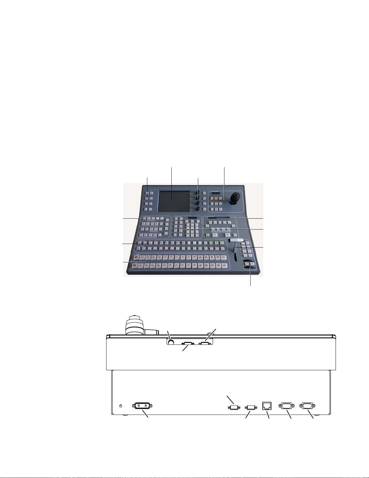
System Components
Kayak Control Surfaces
Kayak Production Switcher systems use a control panel with an integrated
menu display (color TFT with touch-screen). The Sidepanel program,
which runs on a user-supplied Windows PC, can also be used to control the
Kayak system.
1 M/E Control Panel
Figure 1. 1 M/E Control Panel, Top View
Graphical Display
Digipots and
Digipots and Menu ButtonsMenu Navigation Buttons
Menu Buttons
System Components
Positioner Subpanel
Keyers Subpanel
Misc Delegation
and Crossbar Selection
Program/Preset
Program/Preset
Crossbar Selection
Crossbar Selection
Figure 2. 1 M/E Control Panel, Rear View
PS/2 Port
(Future use)
Kayak DD-1 Panel
Main Transition
Subpanel
Effect Subpanel
Transition Lever
2nd Transition Subpanel
USB #4
(Future use)
48V DC Power In (from Frame)
USB #2
LAN RS 485 RS 232
Kayak — User Manual 25
8448_04_r0
Page 26
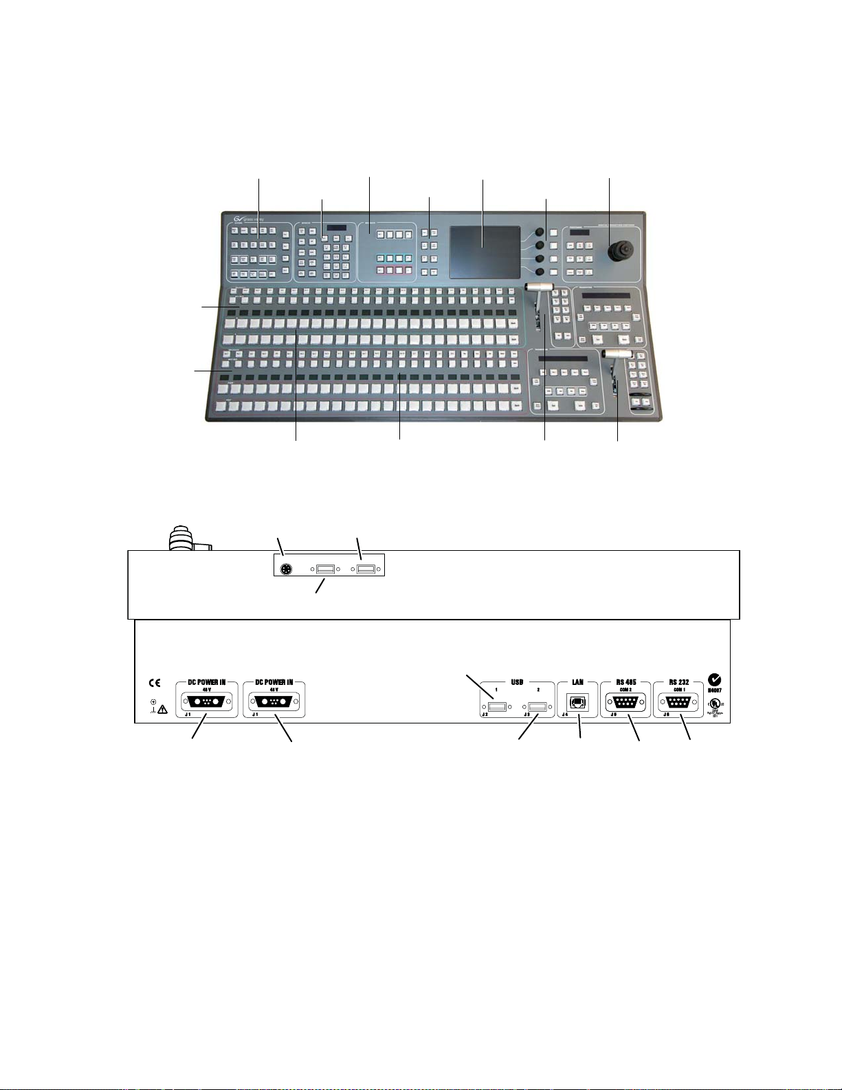
Section 1 — System Overview
1.5 and 2 M/E Control Panel
Figure 3. Kayak 2 M/E Control Panel
M/E1
P/P
Delegation SubpanelKeyers Subpanel
Effect Subpanel
Graphical Display
Menu Navigation Buttons
Positioner Subpanel
Digipots and Menu Buttons
Kayak DD-2 Panel
48V DC Power In
(from Frame)
M/E1
Misc Delegation
and Crossbar Selection
P/P
Misc Delegation
and Crossbar Selection
Figure 4. 2 M/E Control Panel, Rear View
PS/2 Port
USB #4
3
USBP/S 2
4
(Future use)
(Future use)
Redundant
DC Power In
Transition Lever M/E1
Transition Subpanels
LAN RS 485 RS 232USB #2
Transition Lever P/P
Transition Subpanels
8448_05_r0
26 Kayak — User Manual
Page 27
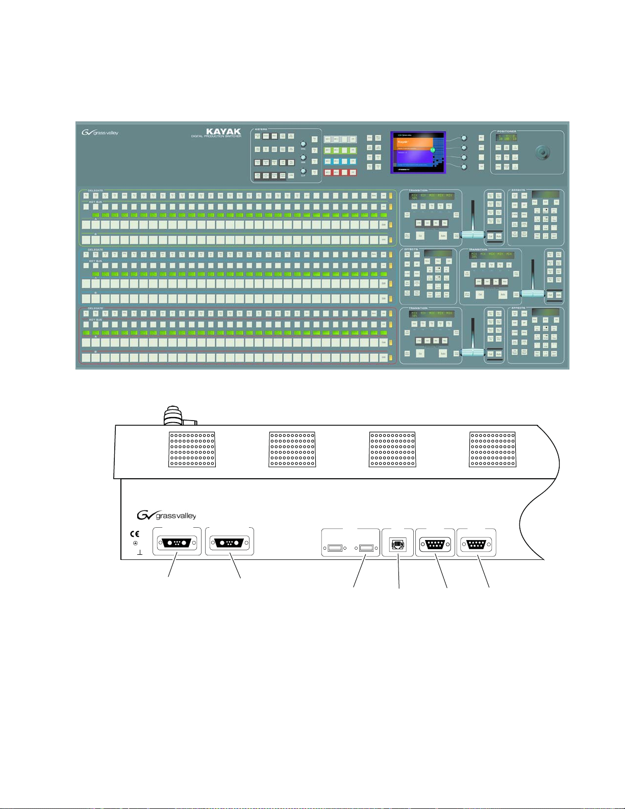
2.5 and 3M/E Control Panel
Figure 5. Kayak HD 250C, 250, and 300 Control Panel
System Components
TE
8448_12_r0
48V DC Power In
(from Frame)
Figure 6. 3 M/E Control Panel, Rear View
KAYAK
DC POWER IN
48V/1.3A max. 48V/1.3A max.
J1A J1B
DIGITAL PRODUCTION SWITCHER
RED. DC POWER IN
USB
1
Spare
J2 J3
Redundant
DC Power In LANUSB
2
LAN RS 485
J4
COM 2
J5
J5
RS 485 RS 232
RS 232
COM 1
Kayak — User Manual 27
Page 28
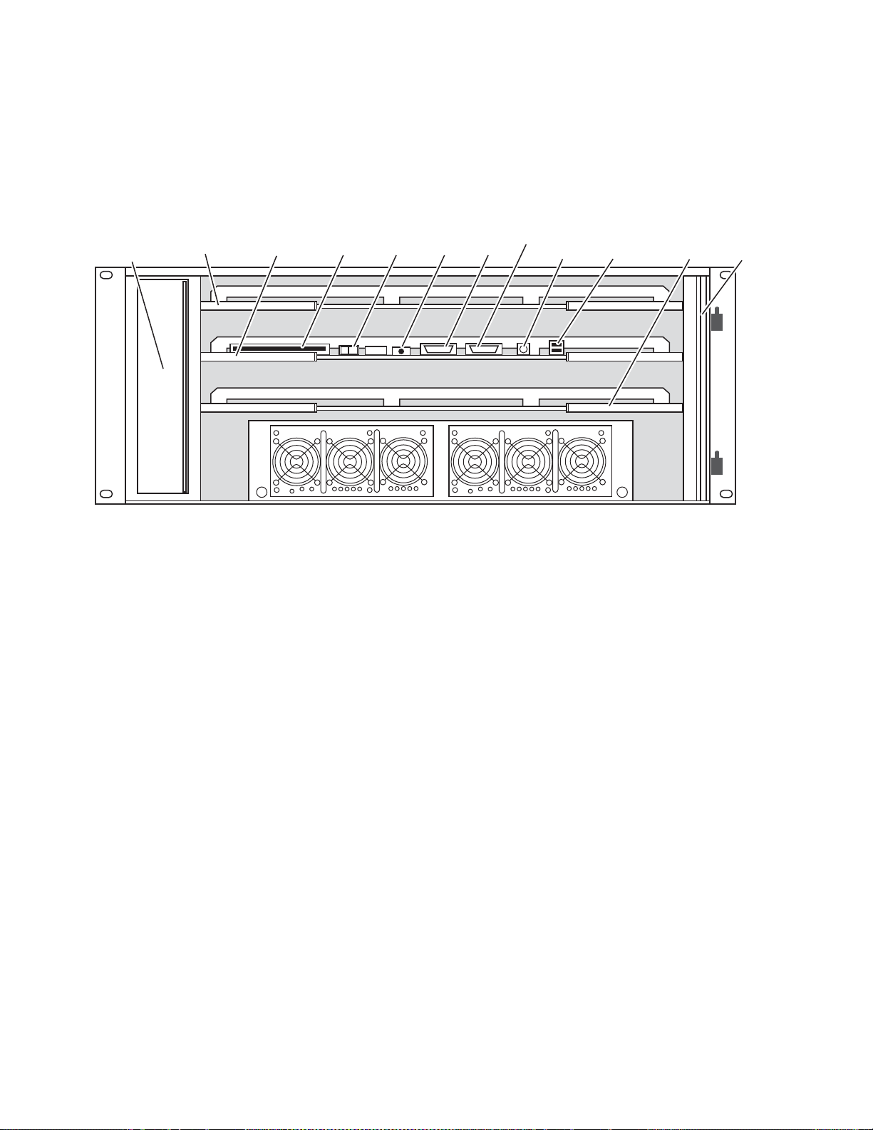
Section 1 — System Overview
Kayak Video Processor Frames
Kayak HD 4 RU Frame
Figure 7. Kayak 4RU Frame, Front View with Door Removed
Fan Assembly
Top M/E Slot
M/E 0 (PP)
Controller
(and 0.5 M/E)
Flash
Memory
ON
OFF
Power
Switch
Reset
Button
RS-232
VGA
PS2
Keyboard
2 USB
(unused)
Bottom M/E Slot
(M/E 1)
Air Filter
Power Supply Unit 1 Redundant Power Supply Unit 2 (option)
8448_01_r1
28 Kayak — User Manual
Page 29
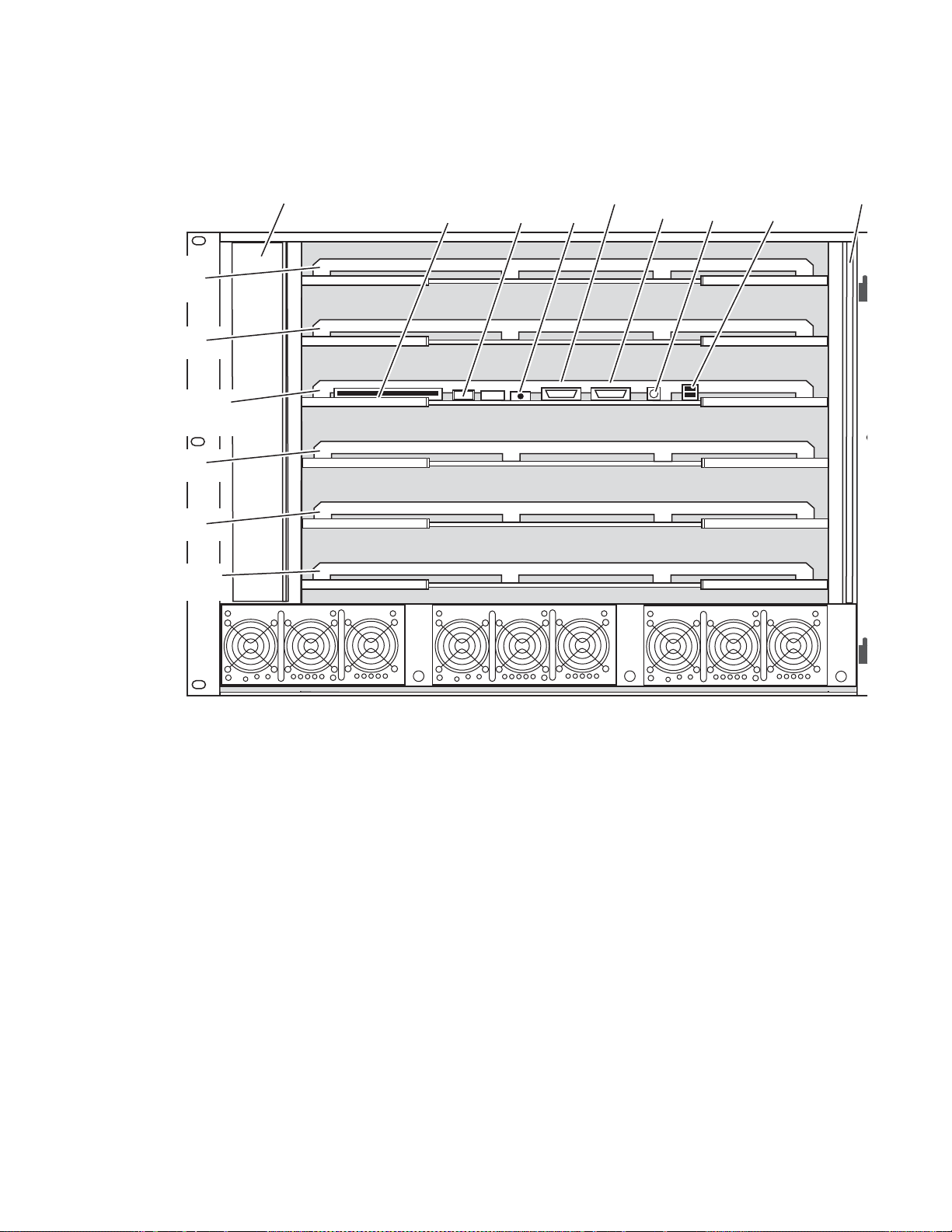
M/E 0
(PP)
M/E 1
Controller
(and 0.5 M/E)
M/E 2
Kayak HD 8 RU Frame
Figure 8. Kayak 8RU Frame, Front View with Door Removed
Fan Assembly Flash
Memory
OFF
System Components
Power
Switch
ON
RS-232 PS2
Reset
Button
VGA
Keyboard
2 USB
(unused)
Air Fi
M/E 3
Expansion
Slot
Power Supply Unit 1 Power Supply Unit 2 Power Supply Unit 3 (Optional)
Kayak — User Manual 29
Page 30
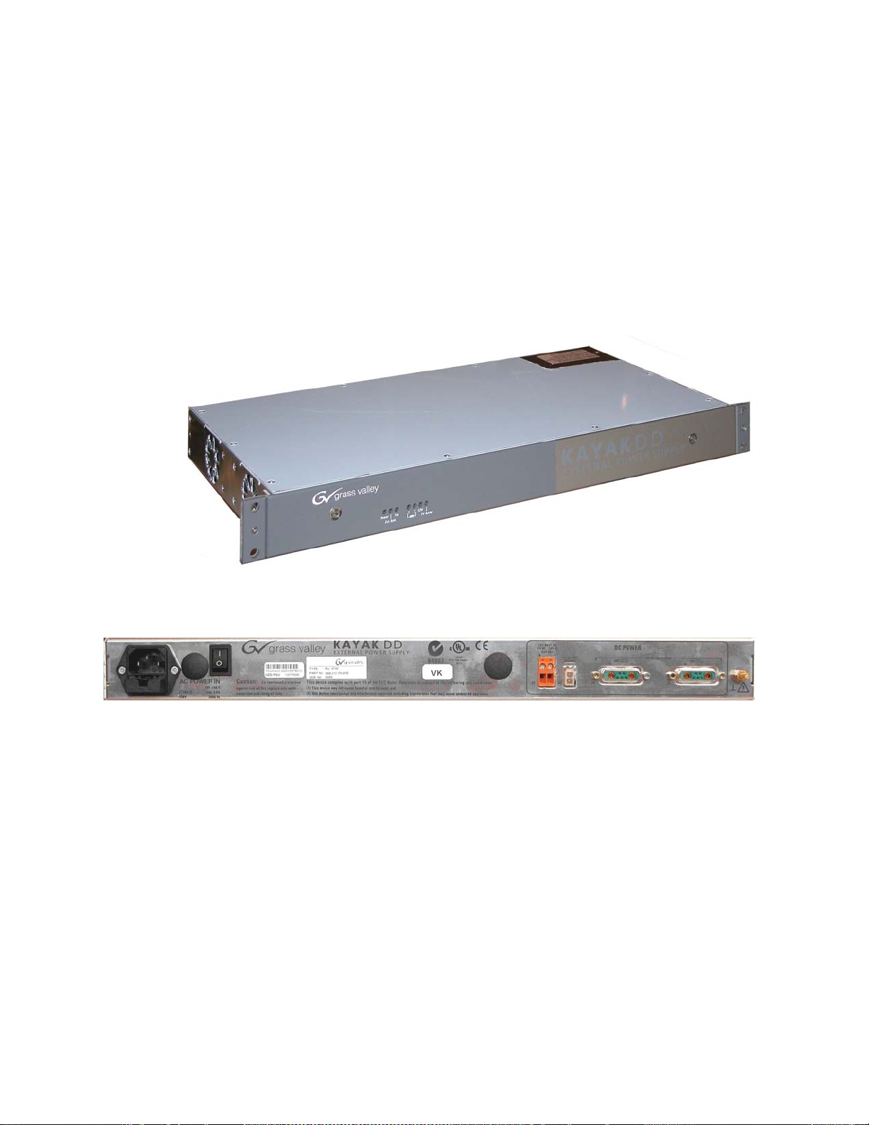
Section 1 — System Overview
KDD-PSU Power Supply Option
The KDD-PSU option is a one-rack unit, wide range AC power supply providing power for a remotely-mounted Kayak Control Panel or for each
additional Control Panel connected to the same processor chassis.
Power output is sufficient for two 1 M/E systems or one 2 M/E system.
Grass Valley recommends that customers purchase this option if the distance from the Frame to the Control Panel is more than 100 meters.
Figure 9. KDD-PSU
KDD-PSU-Front-Left
Figure 10. KDD-PSU Rear View
8448_17_r0
30 Kayak — User Manual
Page 31

Video Signal Flow
The basic video signal flow (Figure 11 on page 32) of the Kayak system has
been designed for operational flexibility. For example, all the outputs from
the M/E are routed back to the video crosspoint matrix, making all these
signals accessible to the entire system.
The video inputs to the Video Processor frame can be mapped to any of the
crosspoint buttons.
Internally generated white, black and three color backgrounds are also
available sources, as are the six RAMRecorder outputs. This source-tobutton mapping is performed through the touch screen menu and can be
stored as a user profi le fo r any numb er o f ind ivid ual user s. Bu tton map ping
is the same on all buses.
The selected video on each bus is deserialized and reclocked before
entering the video processing circuitry. Video processing is available for
each separate M/E background, Key, and Utility bus. In addition, contrast,
brightness, and hue can be adjusted on a bus-by-bus basis.
Video Signal Flow
Each M/E has four full-function keyers with optional internal Digital
Picture Manipulator effects. Each keyer has access to its own wipe generator as well as a pair of standard flexible chroma keyers which may be
assigned to any keyers in the system. Two complex wipe generators serve
each M/E, providing a wide range of wipe choices with modulation, rotation and multiplication of each one. Wipe signals can also be taken from the
two Utility buses on the M/E.
The outputs from M/E Program, Preview, and clean feed are fed back to the
crosspoint circuitry for the selection on the Auxiliary buses as well as the
clean feed output.
The AUX bus outputs can be utilized in a number of ways. Every AUX bus
provides individually adjustable safe area and crosshair (center cross)
capability. Each AUX bus is timed to the reference.
Kayak — User Manual 31
Page 32

Section 1 — System Overview
Figure 11. KayakHD Video Signal Flow
Main Board
1
2
3
4
5
6
7
8
9
10
11
12
13
14
15
16
17
18
19
20
21
22
23
24
Crosspoint
144 x 144
M/E 1 Mix Eect Board
M/E 1 Key 1 Video
M/E 1 Key 1 Key
M/E 1 Key 2 Video
M/E 1 Key 2 Key
M/E 1 Bkg A
M/E 1 Bkg B
M/E 1 Key 3 Video
M/E 1 Key 3 Key
M/E 1 Key 4 Video
M/E 1 Key 4 Key
M/E 1 Bkg C
M/E 1 Bkg D
Eect Send Return 1
Eect Send Return 2
Eect Send Return 3
Eect Send Return 4
M/E 1 Pgm A
M/E 1 Pvw A
M/E 1 Pgm B
M/E 1 Pvw B
M/E 1 Eect Send 1
M/E 1 Eect Send 2
Section A
Section B
A T
Des
A T
Des
A T
Des
A T
Des
A T
Des
A T
Des
2 Complex Wipe Gen
A T
Des
A T
Des
A T
Des
A T
Des
A T
Des
A T
Des
2 Complex Wipe Gen
A T
Des
A T
Des
A T
Des
A T
Des
Σ
Σ
Σ
Σ
2 Key Wipe Gen
Σ
Σ
Σ
Σ
Σ
Σ
2 Key Wipe Gen
Σ
Σ
Σ
Σ
Σ
Σ
Key
Processing
Background
Processing
Key
Processing
Background
Processing
Variable Delay
Des
Variable Delay
Des
Variable Delay
Des
Variable Delay
Des
Variable Delay
Des
Variable Delay
Des
Variable Delay
Des
Variable Delay
Des
Variable Delay
Des
Variable Delay
Des
Variable Delay
Des
Variable Delay
Des
Mixer
Σ
Σ
Σ
Σ
Σ
Σ
Σ
Σ
Σ
Σ
Σ
Σ
Transform
Transform
Eects Send 1
Eects Send 2
Eects Send 3
Eects Send 4
Σ
Σ
Engine
Σ
Σ
Engine
Σ
Σ
Σ
Σ
Video Proc
Video Proc
Video Proc
Video Proc
Video Proc
Video Proc
Video Proc
Video Proc
Video Proc
Video Proc
Video Proc
Video Proc
Pgm A
Pvw A
Pgm B
Pvw B
Ser
Ser
Ser
Ser
Ser
Ser
Ser
Ser
Ser
Ser
Ser
Ser
Ser
Ser
Ser
Ser
Ser
Ser
Ser
Ser
1
2
3
4
5
6
7
8
9
10
11
12
Future Use
25
to
48
Analog HD Reference
Analog SD Reference
Ram Recorder/
Stillstore
Background
Generator
Sync Generator
Timing Analyzer
Ch 1
Ch 2
Ch 3
Ch 4
Ch 5
Ch 6
Ch 1
Ch 2
Ch 3
Ch 4
Ch 5
Ch 6
Bgk 1
Bgk 2
Black
White
Des
Σ
Des
Σ
Des
Σ
Des
Σ
Des
Σ
Des
Σ
Ser
Σ
Ser
Σ
Ser
Σ
Ser
Σ
Ser
Σ
Ser
Σ
Ser
Σ
Ser
Σ
Ser
Σ
Ser
Σ
Digital Reference
Des
Σ
Timing Analyzer
Des
Σ
M/E 2 Mix Eect Board
HM/E Key 1 Video
HM/E Key 1 Key
HM/E Key 2 Video
HM/E Key 2 Key
HM/E Key 3 Video
HM/E Key 3 Key
HM/E Key 4 Video
HM/E Key 4 Key
HM/E Bkg A
HM/E Bkg B
HM/E Pgm A
HM/E Pvw A
HM/E Pgm B
HM/E Pvw B
Float 1 Key Video
Float 1 Key Key
Float 1 Bkg
Float 2 Key Video
Float 2 Key Key
Float 2 Bkg
Float 1 Mix
Float 2 Mix
A T
Des
A T
Des
A T
Des
A T
Des
A T
Des
A T
Des
A T
Des
A T
Des
A T
Des
A T
Des
A T
Des
A T
Des
A T
Des
A T
Des
A T
Des
A T
Des
Variable Delay
Des
Variable Delay
Des
Float
Σ
Half M/E
Σ
DSK
Σ
Σ
Σ
Σ
Σ
Σ
Σ
Σ
Pgm A
Ser
Σ
Pvw A
Ser
Σ
Pgm B
Ser
Σ
Pvw B
Ser
Σ
Video Proc
Σ
Video Proc
Σ
Des
Deserializer
Auto Timer
A T
Σ
Diagnostic Checksum Accumulator
Ser
Serializer
1.485 Gb/s or 270 Mb/s Dierential Serial
SMPTE SD or HD SDI
Various Parallel Video Buses
Kayak HD
2½ M/E Simplied
Ser
Ser
Video Block Diagram
Float
Keyer
Mixer
Float
Keyer
Mixer
Float 1 Mix
Ser
Σ
&
Float 2 Mix
Ser
Σ
&
Σ
Σ
Σ
Σ
Σ
Σ
32 Kayak — User Manual
13
to
48
8448_02_r0
Page 33

iDPM
iDPM
Video
Proc
Video
Proc
AUX
Proc
PP: Single Mixer Eect (Plug-In Board) RY 3720
ME: Single Mixer Eect (Plug-In Board) RY 3930
Main Board RY 3910
Figure 12. KayakDD Vidoe Signal Flow
Video Signal Flow
8448_62
Kayak — User Manual 33
Page 34

Section 1 — System Overview
34 Kayak — User Manual
Page 35

Concepts
Introduction
Section 2
In general, any video switcher receives multiple video inputs, performs
signal processing on selected input signals, and then outputs the processed
video. Efficient real time switcher operation is essential for live production,
and can save valuable time in post production environments as well.
Several innovative concepts are employed in the KayakDigital Production
Switcher to enhance its operational speed and flexibility. Understanding
these concepts, as well as basic switcher fundamentals, will help you take
full advantage of the exceptional power of the Kayak system.
Kayak System Configuration Overview
The Kayak Digital Production Switcher is designed for operational flexibility, and can be configured to fit various applications. Different Kayak
systems can have different capabilities, or the same Kayak system can be reconfigured to have different capabilities at different times.
The way a Kayak Digital Production Switcher is wired into your facility
affects the Kayak system’s capabilities. For example, the number of sources
physically connected to the system obviously determines what video the
system can handle. However, because Kayak system video/key inputs and
AUX Bus outputs can be configured, once video cables are physically connected they need not be moved. Configuration settings also control many
other capabilities that affect Kayak system behavior.
Kayak Digital Production Switcher configuration information is divided
into three areas:
• Installation (Engineering Setups) (settings established by the engineer
in charge that affect the entire system, which never need to be changed
by operators),
• Configuration (settings for e.g. a production that affect all the operators
working in that suite, that are designed to suit a particular show or production style and ensure a consistent working environment), and
Kayak — User Manual 35
Page 36

Section 2 — Concepts
• Personality Setting (settings that give the operator the ability to customize his individual work surface to meet his personal preferences).
All Kayak settings are non-volatile. Disk save and load operations are
available via the Sidepanel Program that allows users to store configuration information on the hard disk of a PC or on a movable media for easy
transport and for use as backup copies.
Installation (Engineering Setups)
Engineering Setups control how the Kayak Digital Production Switcher’s
major components behave and interact, and how the Kayak system interacts with the rest of the facility.
Engineering Setups are not likely to change on a daily basis and so are
grouped separately from Configurations and Personality Settings. Facility
maintenance personnel or the engineer in charge of a production truck generally manages Engineering Setups. These parameters are usually set
during installation.
Engineering Setups information includes:
• Networking (IP addresses),
• Timing, Type of Reference signal
• External device interfaces (DDRs, VTRs, DPM, Router, AUX Control
Panels, etc.),
• Various other system functions
Config — Application Control
The configuration defines how the control surfaces associated with a Kayak
suite behave. A configuration can substantially change system behavior,
not just a user’s view of the system. The configuration is saved in applications and is intended for day-to-day or session-to-session changes in Kayak
system operating behavior. Applications are open for modification by operators.
Loading and Storing applications can be performed using the Sidepanel
(
Config) and also with the Control Panel Menu (Config / Appli Control).
Config Applications include:
• E-MEM
• Macros
• Key Memory
• Pattern Memory
36 Kayak — User Manual
Page 37

• Safe title behavior
• Video specifications (such as aspect ratio)
• Various other suite functions
Personal Settings
Personal Settings allow users to customize a Kayak control surface to suit
their personal operational style. User Preferences do not change Kayak
system capabilities. Loading and Storing Personal Settings is possible via
the Sidepanel Program
Personal Settings include:
• Menu delegation behavior,
• Shift preferences
• Various other user functions.
General Rule:
Signal Routing
Signal Routing
Inputs and Sources
• All setup changes, which will not work without an physical change of
a device, are part of Installation (menu).
• All setup changes, which will work without an physical change of a
device, are part of Configuration (menu).
Setting up the type, the address, and the connection port for an auxiliary
control panel is part of Installation. Configuring the behavior and the
button assignment of this AUX CP is part of a configuration.
Kayak HD
Incoming video signals are connected to the Kayak HD system via BNC
connectors on the rear of the Kayak HD Digital Processor frame. All inputs
are serial digital (SMPTE 274M, SMPTE 296M, SMPTE RP211). Signals from
external devices not operating in this standard will need to be converted.
Some devices (for example, a camera providing serial digital output) may
provide a video signal that can be received on a single connector. However,
other devices may output multiple signals.
Kayak — User Manual 37
Page 38

Section 2 — Concepts
Kayak DD
For example, a character generator usually provides a signal with two components (commonly called video and key). Some incoming signals may also
originate from devices the Kayak HD system can control (Router, DPM,
DDR).
For a Kayak HD Digital Production Switcher, the term source refers to all the
video signals and other attributes associated with a device. This is a fundamental concept. The Kayak HD system is based on sources, not input
signals or crosspoints. Each source can be given a descriptive name, but has
an ID Number for absolute identification. The Kayak HD system uses ID
numbers, not source names or input connectors, to identify each source.
Defining each source is an important aspect of the Kayak HD system.
Incoming video signals are connected to the KayakDD system via BNC
connectors on the rear of the KayakDD Digital Processor frame. All inputs
are serial digital (SMPTE 259M, CCIR 601). Signals from external devices
not operating in this standard will need to be converted.
Some devices (for example, a camera providing serial digital output) may
provide a video signal that can be received on a single connector. However,
other devices may output multiple signals.
For example, a character generator usually provides a signal with two components (commonly called video and key). Some incoming signals may also
originate from devices the KayakDD system can control (Router, DPM,
DDR).
For a KayakDD Digital Production Switcher, the term source refers to all the
video signals and other attributes associated with a device. This is a fundamental concept. The KayakDD system is based on sources, not input
signals or crosspoints. Each source can be given a descriptive name, but has
an ID Number for absolute identification. The KayakDD system uses ID
numbers, not source names or input connectors, to identify each source.
Defining each source is an important aspect of the KayakDD system.
Source Definition
The source definition process includes assigning a name to each input
source. Once sources are defined, you can then select the source by name in
the control panel menu. Sources that use separate video and key signals are
coupled in the Input menu to allow a single button to select the video-key
pair from the switcher control panel. Tally relays can be assigned to the corresponding inputs in the
of a configuration and may change from production to production.
Config - GPO/Tally menu. All these settings are part
38 Kayak — User Manual
Page 39

Button Assignment (Source to Button Mapping)
Source to button mapping makes it possible to organize sources on Kayak
control panels to suit your personal preferences. For example, cameras can
be grouped into a set of buttons on the left side or the right side of a button
row, or in any way that is desired or convenient.
Source mapping is distinct from source definition, as source mapping only
involves the location of sources on the control panel and does not affect the
inputs or names defined for the sources.
For details on how to assign sources to buttons please refer to the Kayak
Installation and Service Manual.
Note E-MEM effects store Source IDs, not the source select buttons, so remapping
sources does not change the appearance of recalled effects.
You can also assign sources to buttons using the Sidepanel program.
Signal Routing
Key Memory
Key parameters can be saved to a separate key memory for every Kayak
system source. These parameters can be applied automatically whenever
that source is selected.
Buses and Crosspoints
A bus is technically defined as a signal path where one of several available
inputs can be selected to feed a single output. A crosspoint is an electronic
switch that allows a signal to pass when the switch is closed. On video
switchers, a bus can be constructed containing a series of crosspoints,
which permits selecting which one of several incoming signals will be sent
out the bus. In Figure 13 on page 39, source 2 has been selected on the back-
ground A bus. This signal can now be called background video and is avail-
able for further processing.
Figure 13. Buses with Crosspoints
8447_01r0
Kayak — User Manual 39
Page 40

Section 2 — Concepts
Buttons on a control panel can be used to control the switching of crosspoints. The buttons are usually arranged horizontally, making it easy to
imagine the available signals coming in from the top, and the single bus
output signal going out the right side. In earlier generation switchers, the
terms crosspoint button and crosspoint bus have been used in reference to
control panel source selection.
For a Kayak system, the terms source button and source bus will be used.
These terms better reflect a system operating philosophy that is source
rather than crosspoint based.
The Kayak system does not directly associate a source select button with a
physical crosspoint. The association goes first through source to button
mapping, then through source definition to find the physical inputs.
On the Kayak system, a single source button can control crosspoints on different buses simultaneously. For example, during keying, both the video
and key signals of a source can be selected with a single button press.
In this case two different crosspoints on separate buses (key fill bus and key
cut bus) are actually switched when the button is pressed.
In the upper part of Figure 14 below, the video component of source 2 in the
figure has been selected on the key fill bus and becomes the key fill signal
for subsequent keying. The key component of source 2 selected on the key
cut bus becomes the key cut signal for keying. The lower part of Figure 14
below shows how the same source (source 4) can be selected for both the
key fill and key cut signals.
Figure 14. Multiple Crosspoint Control
8324_07_r1
40 Kayak — User Manual
Page 41

Shifted Sources
An operator may need to quickly access many sources during a production.
However, a control panel has size limitations, since all the source selection
buttons must remain within reach. The Kayak system provides shifted
buttons to allow access to more input sources from the control panel.
For example, on the Kayak HD-100 system, up to 28 sources can be mapped
at one time, 14 to the unshifted source selection, and 14 to the shifted buttons. A dedicated
button (Crosspoint 15) for every bus. Two shift modes are available:
Normal and Latched.
In Normal mode, shifted or unshifted status of the bus is indicated by the
state of the
a source button always selects the shifted source for that bus.
The
Signal Routing
Shift button is provided as the farthest right crosspoint
Shift button light. Holding down the Shift button while pressing
Shift button will light when the row of buttons to its left are shifted.
In Latched mode, the
Caps Lock button on a standard keyboard. When on, it lights to indicate
the
that the subsequent selection(s) on the crosspoint selector row will be made
from the shifted set of sources (15 through 28). When off, the subsequent
selection(s) come from the unshifted set (1 through 14). If the user toggles
the
Shift button to the state that is opposite from the shift state for the cur-
rently selected input, then the crosspoint selector button blinks to indicate
this “out of sync” condition.
A useful configuration is to have sources normally used for backgrounds
(e.g. VTRs) mapped to unshifted buttons, and sources normally used as
keys (e.g. character generators) mapped to shifted buttons. Then you can
then set all the background buses to an unshifted preference, and all the key
buses to a shifted preference. All normal source selections can then be made
without having to use the shift modifier buttons.
It is also possible to have a different assignment for background and key
buses.
Source Scalars (HD Only)
Each Mix Effects (M/E) has 4 scalars that can be used for scaling video
sources of the same frame rate but different resolutions than the video
being processed.
Shift button toggles on and off in a manner similar to
The scalars are software enabled options. Two scalars are enabled on one
option, up to 2 options per M/E maximum. The scalars are fixed to a specific M/E.
Kayak — User Manual 41
Page 42

Section 2 — Concepts
Mix/Effects (M/E) Stage
Each M/E of the Kayak system can create a composite of two or more pictures. It includes multiple source selection buses and provides transition
(mix and wipe) and keying capabilities on the selected signals.
The M/E can be organized with the keying circuitry separate from the
mixing circuitry, which permits Effect Send capabilities (see Effects Send on
page 43 for more information).
A simple basic M/E used in a typical switcher will be used as an example
in the following discussion. The Kayak M/E has added capabilities, but the
basic principles described here will apply.
Figure 15. Simplified Mix Effects (M/E) Subsystem
Source Signal Inputs
Wipe
Generator
M/E
Outputs
M/E Program
M/E Preview
061_00_22_r1
Crosspoint
Matrix
Key Fill
Key Cut
Background A
Background B
Keyer
Mixer
The basic M/E shown in Figure 15 on page 42 has an A and a B background
bus. These buses select the background video signals sent to the output of
the M/E.
Generally the source on the background A bus is the current background
output, and the source on the background B bus is the background video
that will be used next. During most transitions, portions of both backgrounds are output simultaneously. The keyers in the M/E allow the inclusion of additional material over the background. Wipe generators also
exist, which create patterns used by the mixer for wipe transitions, or used
by the keyers to modify the signals it sends the mixer.
The processed signal in an M/E is then sent to an M/E output, typically
program or preview (or can be selected as input in the second M/E).
Alternate Buses and Delegation
Many earlier generation switchers had M/Es equipped with two keyers,
and each M/E could accept two background sources. This permitted
mixing or wiping between two backgrounds, and keying up to two additional sources over the background. Dedicated rows of control panel
buttons were used to select these key and background signals.
42 Kayak — User Manual
Page 43

Mix/Effects (M/E) Stage
The Kayak system M/E actually has four keyers, each handling a fill and a
key signal, and it can accept three background sources (A, B, and Utility).
Providing individual source selection rows for each bus is impractical, as
the panel would become too large. For ease of use, Kayak panels have alternate buses accessed by delegation, using Key and PVW/AUX delegation
via the Miscellaneous Bus selection subpanels.
Utility Bus
Besides the standard A and B background inputs, each Kayak also accepts
two Utility inputs. The Utility buses can be used to select signals for special
purposes, and has no relation to the background buses. For example, a
video signal selected on the Utility bus can be used to feed a custom pattern
into a wipe generator, or create a custom border wash pattern.
Effects Send
Effects Send provides a method of integrating digital effects devices into
the M/E. Effects Send switches the key cut and key fill outputs of the keyer
of the M/E to a digital effects device for manipulation. The manipulated
key cut and key fill outputs are then received and sent directly to the inputs
of the mixer circuits of the M/E. Effects Send allows you to process a key
effect as though the digital effects circuits were located inside the M/E
itself.
On the Kayak system, Effects Send is integrated into the M/E and is an
extension of the keying control system.
Figure 16. Effects Send Diagram
Digital
Source Signal Inputs
Source
Selection
Buses
Keyer
M/E
Effects
System
Mixer
M/E
Outputs
0618_00_24
If the Kayak system is equipped with the optional Digital Picture Manipulator option, the effects become part of the internal M/E’s mixer.
Kayak — User Manual 43
Page 44

Section 2 — Concepts
Kayak HD Outputs
Kayak HD AUX Busses and Output Assignments
Kayak DD Outputs
Video production switchers generate several different video outputs (such
as Program, Preview, AUX busses, and others). A final program output
(Main or DSK) is typically sent to the transmitter for broadcast and/or to
output devices for recording.
AUX Bus outputs may also be used for special purposes.
Kayak HD switchers provide 12 outputs per M/E. This means you can
have up to 24 outputs in the compact frame and up to 48 in the large frame.
For installed M/E boards the rear BNC outputs are active.
Any internal source can be assigned to these AUX bus outputs for monitoring. Safe Title can also be enabled on any of these AUX busses.
Video production switchers generate several different video outputs (Program, Preview, etc.). A final program output from PGM is typically sent to
the transmitter for broadcast and/or to output devices for recording.
Aux Bus outputs may also be used for special purposes.
Kayak DD Program and Preview Output Busses
For each M/E, the KayakDD system has dedicated BNC output connectors
for the following signals:
2x Program
•
• 1x Preview
• 1x Clean
• 1x Clean Preview
In addition
• 1x Aux 1 … Aux 10
Kayak DD Aux Busses
Video production switcher Aux Buses can be used to select and route
sources to specific destinations. For example, a source selected on an Aux
bus can be sent to an recorder for instant replay. This can be done directly
by the Technical Director while he/she switches the program.
Remote Aux panels can be used to give different operators control over one
or more Aux buses.
44 Kayak — User Manual
Page 45

The KayakDD system has 1 dedicated BNC output connector per aux bus.
Resource Sharing and Point Of Use
The Kayak system can share some resources for use at different locations.
The location where a resource is being used is called a point of use.
The wipe pattern generator resources can be used for an M/E wipe transition, as a preset pattern, as a mask, or at other points of use. It is also possible to assign the output of the same wipe pattern generator to different
points of use at the same time.
For efficient operation, the Kayak system has divided the parameters controlling wipe pattern generators and related utility bus functions into two
categories; shared generator parameters and point of use parameters.
The set of parameters for the shared generator are used by all points of use,
so changing one of these parameters will affect all locations where that
wipe pattern generator is being used at that time. Separate sets of point of
use parameters, however, are maintained for each Kayak system point of
use.
Resource Sharing and Point Of Use
Transition
These settings are used only by each individual points of use, so changing
them will not affect any other point of use.
For example, a wipe shape (box, circle, etc.) is a generator parameter, but
the softness of the shape’s edges is a point of use parameter. If the same
wipe generator is used by both an M/E wipe transition and a preset pattern, adjusting softness at one point of use will not affect the other’s softness settings. However, changing the pattern shape affects both locations.
A transition is a change from one image to another. The Kayak system supports three basic types of transitions:
•Cut
•Mix
•Wipe
•DPM (optional)
A transition can be applied to the entire picture, or to only the background
or keyed elements of the picture, and can include multiple elements.
Kayak — User Manual 45
Page 46

Section 2 — Concepts
Cut
Mix
A cut is an instantaneous switch from one image to another (between successive video fields or frames). The simplest type is a hot cut, accomplished
by selecting a different source on a bus feeding an M/E output. This only
changes that bus’s contribution to the output, and does not change what
elements may be involved in the output (the same buses are involved).
The Kayak system also provides cut transitions, where the elements
involved in a composite can be changed instantaneously. Different buses
can be included or excluded, causing changes in the resulting composite
image. Background cut transitions on The M/E are first selected on the
Background B bus to allow previewing the upcoming picture before it is cut
On Air.
A mix is a transition from one picture to another where the new picture
fades in as the existing picture fades out. During a standard mix transition
a superimposition of both pictures, each at a lower intensity, is visible.
The Kayak system allows mixing from one background to another and to
mix up to four separate keys on or off over a background. Background and
key mixes can be done separately or simultaneously.
Full Additive Mix
Full Additive Mix (FAM) is a special mix transition that the Kayak system
supports besides normal crossfade transitions. Picture elements in FAM
transitions are composited differently through the time of the transition.
Figure 17. Normal and FAM Mixes
8447_05r0
46 Kayak — User Manual
Page 47

Wipes
Transition
FAM transitions first fade a new picture to full intensity and then fade the
old picture out, but both full intensity pictures are mixed together to the
output during the transition. The resulting signal is clipped at white level
to prevent generating illegal video.
A wipe is a transition from one picture to another in which the edge of a
shape moves across the screen, revealing the new picture. Wipe transitions
can be applied to backgrounds, to keys, or to both simultaneously. A wipe
transition shape can be selected from a variety of patterns, and these patterns can be adjusted in several ways (position, aspect ratios, edge
attributes, etc.).
Each Kayak M/E has two separate transition wipe systems, each of which
can be assigned a different wipe pattern and be adjusted independently.
These systems can each use one of the two available complex wipe pattern
generators with advanced capabilities. It is also possible to combine these
wipes to create extremely complicated wipe transition shapes, and generally this is used only by advanced operators. Utility bus video signals can
also be used to generate a custom pattern for a wipe transition or other purposes.
Other Wipe Pattern Generator Uses
Wipe pattern generator circuitry can be used for purposes that do not
involve transitions. Each Kayak M/E has the two complex wipe pattern
generators described above, and each of its four Keyers also has a simple
pattern generator and a box pattern generator, making a total of six wipe
generators. These pattern generators can also be used for Preset Pattern,
Masking, and Matte Washes.
Preset Black
Preset Black is a special type of transition, where the picture transitions to
black, and then transitions out of black to the new picture. Preset Black is
really two transitions, one to and one from black, and so requires two operator commands to complete. Preset Black can be used with any transition
type (cut, mix, or wipe). The entire picture goes to black, even if all the transition elements involved in the picture were not selected.
Fade to Black
The Fade to Black control in the DSK allows the Program output of the
switcher to be brought down to black at a predetermined transition rate.
Kayak — User Manual 47
Page 48

Section 2 — Concepts
Transition Rate
Flip Flop Background Buses
Cut transitions are instantaneous, but mix and wipe transitions have durations.
Transition durations can be set in advance to a specific transition rate, and
be initiated by pressing a button on the control panel. It is also possible to
manually control transitions using a lever arm.
On the Kayak system, one transition rate can be assigned to the main transition of the M/E. This type of transition can be controlled by that M/E’s
lever arm. Each of the four keyers on the M/E can also be assigned its own
transition rate, initiated with a separate
At the completion of a transition, the background buses swap their source
selections (flip flop). This makes the upper bus always act as the on-air bus,
and the lower bus act as a preset bus. The operator can reliably setup the
next source on the lower bus without disturbing the source selected on the
on-air upper bus.
Key Mix button.
For example, if a transition begins with source 1 on Background A and goes
to source 2 on Background B, as soon at the transition to source 2 completes,
source 2 will be taken to the Background A bus (without disturbing the
output of the M/E). The source 1 selection will also be immediately taken
to the Background B bus.
Look Ahead Preview
If a preview monitor is configured for Look Ahead Preview mode, the end
result of the upcoming transition can be viewed on that monitor. This lets
the operator know in advance what will occur for that next transition.
Current and Next Stack
Kayak uses a current and next stack approach for transitions that involve
multiple elements. The current stack is the current M/E output including
any keys that are on. The next stack is defined by the current stack and
whatever next transition elements have been selected. Look ahead preview
always displays the next stack. Next transition elements affecting stacks are
Keys 1 - 4, background, and key priority.
Kayak transitions always occur from the current stack to the next stack.
For example, if the current stack has Key 1 over Background A, and the next
stack specifies Key 2 over Background B, a mix transition will occur
between the composites (Key 1 over A to Key 2 over B). This is different
48 Kayak — User Manual
Page 49

Keying
from mixing Key 1 off, Key 2 on, and mixing between A and B at the same
time, which would cause the keys to go transparent over their background
during the transition.
On the Kayak system, opacity is retained throughout the transition, so
midway through this example Key 1 remains fully keyed over Background
A, and Key 2 is fully keyed over Background B. The transition occurs
between these two fully keyed composites.
If multiple keys are faded in or out using the separate
has it’s opacity changed with relation to all other keys. This means that
keyer transitioned this way or no longer considered part of the composite
and will show transparency.
Key Priority and Transitions
The four keyers on a Kayak M/E can be assigned priorities. This determines the layering of the keys. The highest priority key appears on top,
while keyers with lower priority may be partially or fully hidden behind
those with higher key priorities. The backgrounds always have the lowest
priority. Changes in key priority can be included as a part of a transition.
Like any other transition, the current stack will transition to the key priority
of the next stack. For example, suppose the current stack has Keys 1, 2, and
3 in that key priority order over Background A, and the next stack specifies
key priority order 3, 2, 1. A mix transition will occur between the 1, 2, 3
composite order to the 3, 2, 1 composite order. All three keys will remain
fully keyed over the background, and will mix to their new key priority
order.
Mix button each keyer
Half M/E and DSK Option
The Half M/E and DSK option is available that adds an additional M/E
with cuts and mixes on backgrounds and keyers. The output of this Half
M/E can be re-entered into any other M/E, and/or be assigned to an Aux
output. The Half M/E is controlled by delegating any switcher bank with
a single button press.
DSK capabilities that adds four extra keyers is also included with this
option. Half M/E and DSK functionality cannot be used simultaneously,
however.
Keying
Keying inserts part of one picture into another to create a composite picture.
Kayak — User Manual 49
Page 50

Section 2 — Concepts
Keying involves three signals:
• Background,
• Key cut, used to specify where to cut a hole in the background, and
• Key fill, used to fill the hole in the background.
The fill can be an incoming video signal or it can be an internally generated
matte fill. A separate key cut input signal is not necessarily required for
keying. For example, a self key (also called a video key) uses the same input
signal for both key cut and key fill.
The Kayak system supports the following types of keys:
• Additive Key
• Luminance Key
•Linear Key
•Chroma Key
• Preset Pattern
The Kayak system also supports self keys and split keys.
Matte Fill Key Example
One of the earliest keying techniques was to use an art card and camera to
perform a luminance key with a matte fill. This type of key is a good
example for explaining basic keying principles because three separate and
independent incoming signals are used.
To insert a green logo into background video, the logo can be printed in
white on black paper and a camera can be focused on it. The signal from the
camera can be selected as the key cut signal and green matte video can be
selected as the key fill signal sent to the keyer. The key cut signal is then
adjusted (clipped) to ignore the black paper and use only the white logo
shape to cut a hole in the background video. The keyer then shapes the key
fill to precisely match the logo-shaped hole cut in the background and fills
it with green matte video. This creates a green logo inserted into the background (Figure 18). Because luminance values of the key cut signal are used
to cut the hole in the background this is called a luminance key.
50 Kayak — User Manual
Page 51

Figure 18. Matte Fill Luminance Keying Example
LOGO
LOGO
Background
Keying
Shaping Video
LOGO
Key Cut
Key Fill
In this keying discussion illustrations rather than actual screen images are
used for simplicity, and because the printing process has difficulty capturing the subtleties of soft key edges.
In the matte key example above, the key fill signal was a full raster color
that did not match the shape of the key cut signal. This key fill signal is
accurately called non-shaped video, but may also be referred to as unshaped
video since both signal types are processed identically during keying.
LOGO
Background with Matte Key Inserted
0618_00_32_r1
Some external devices (e.g., character generators) provide a key cut signal
and an already processed companion key fill signal. A key fill signal that
correctly matches the key cut signal is called shaped video. During keying,
properly shaped key fill video can be summed with a background signal
(with a hole cut) and achieve the desired result.
The appropriate key mode for this type of signal is the additive key.
If a key fill does not match the hole in the background (like in the matte key
example above), the key fill needs to be shaped by the switcher. By multiplying the key fill signal with the key control signal the unwanted areas of
the fill can be made black, shaping the video to match the hole before it is
summed with the background. Key fill video must be shaped using the key
Kayak — User Manual 51
cut signal actually used to create the hole in the background. Video shaped
with a different key cut signal will not key correctly.
The appropriate key mode for this type of signal is the Linear key or Luminance Key.
Page 52

Section 2 — Concepts
Key Control Signal Adjustment
See the section on Properly and Improperly Shaped Video on page 62 for more
information.
Note that an unshaped signal viewed directly will show harsh edge artifacts due to dividing by a small number. This is normal and expected.
Keying this signal will clean up its appearance.
During keying, the selected key cut signal can be converted into a key
control signal. It is the key control signal that actually cuts the hole in the
background video. Adjusting the key control signal (Clip and Gain) is
essential in the keying process. The art of setting up a good key is to use just
enough Gain to suppress any imperfections in the incoming key signals.
Setting Gain too high can cause ragged key edges.
The Kayak system provides two methods for adjusting the key control
signal, Clip and Gain, and Clip Hi and Clip Lo. Note that the same basic
keying process is controlled by either of these methods.
Clip and Gain
Video
Retained
Mix of
Background
and Fill Video
Clip
Video
Removed
The Clip and Gain operation selects a threshold of the selected key cut
video that will be used to cut the hole in the background video. Clip controls the threshold, and Gain controls the softness of the key edges and any
translucent areas. High portions of the key cut signal specifies what video
is retained, and low portions determine what video is removed. Intermediate levels specify a soft blend of the background and fill video.
Figure 19. Key Clip, Gain, and Key Control Signal
Background Video
Removd
Gain
Key Control
Signal
Key Cut
Signal
Key Control
Signal
Inverted
(Hole Cutter)
Background Video
Retained
0618_00_31_r1
52 Kayak — User Manual
Page 53

Clip and Gain control is appropriate for high gain keys (see below), to
easily adjust where the relatively hard transition from background to fill
occurs. In this mode, changing the Clip control moves the threshold up and
down without affecting Gain, which is adjusted separately with its own
Gain control.
High Gain, Low Gain, and Unity Gain
A high gain key has a narrow range, creating harder key edges. A low gain
key has a wider range, creating softer key edges. Linear keys typically use
minimal gain (also called unity gain) to completely preserve the soft edges
of the keys (Figure 20). Note that the Kayak system also supports keys that
go below unity gain.
Figure 20. Keying Gain Values
Gain
Gain
Keying
Gain
Clip
High Gain Low Gain
On the Kayak system, Gain has a percentage value. A Gain value of 50%
requires a luminance change of 50% of the distance between black and
white to produce a keying signal ranging from transparent to opaque. A
gain value of 100% (unity gain) uses the entire range between black and
white for this transparent to opaque transition. A gain value of 0% produces the hard key edges (a high gain key).
Clip Hi and Clip Lo
The Kayak system also supports a Clip Hi and Clip Lo mechanism. With
Clip Hi and Clip Lo, two thresholds are established. The upper threshold
specifies at what point video will be completely removed from the background, and the lower threshold determines at what point background
video will be retained completely intact.
Clip
Clip
Unity Gain
0618_00_30_r1
Kayak — User Manual 53
Page 54

Section 2 — Concepts
Figure 21. Key Hi, Clip Lo vs. Clip and Gain
Clip Hi
Clip Lo
Key Cut
Signal
Clip
Gain
0618_00_29
In this mode, Gain changes when either control is adjusted. The difference
between the upper and lower keying thresholds is equivalent to gain:
• Clip Hi = Clip + Gain/2
• Clip Lo = Clip – Gain/2
Clip Hi and Lo control is more appropriate for low gain keys, to allow independent control of the two thresholds. For example, when adjusting a
linear key the operator wants to control where the fill becomes opaque
(Clip Hi) and where the fill becomes transparent (Clip Low). In Clip Hi/Lo
mode adjusting the point of opacity does not change the point of transparency, and vice versa.
Clip, Gain, Clip Hi and Clip Low adjustments always interact. Changing
one always results in changes to two other values. Changing Clip Hi or Clip
Low changes both Clip and Gain, not just Gain.
S-Shaped Key Signals
On the Kayak system, an S-shaping function is applied to the edges of luminance keys. S-shaping smooths the sharp corners of a luminance key
control signal, which helps prevent banding artifacts. S-shaping a signal
minimally affects the key edges, and does not move key thresholds or affect
the overall gain of the key.
Figure 22. S-Shaped Luminance Key Control Signal
Key Control Signal
S-Shaped
Key Control Signal
0618_01_33_r1
54 Kayak — User Manual
Page 55

S-shaping is generally not applied to linear keys because the external
device usually applies an S-shaping function when it generates the key cut
and key fill signals. S-shaping should not be applied twice.
Additional Keying Controls
The following additional controls are available for keying.
Key Invert
Keys can be inverted, causing holes to be cut in the background where a
normal key retains the background, and vice versa. Key invert makes the
white areas of the key cut signal produce transparency, and the black areas
produce opacity, the opposite of a standard key.
Masking
Masking defines areas that are protected from keying (Inhibit Mask) or
always key (Force Mask). The shape of the mask can originate from a wipe
pattern generator or by a selected mask signal (typically a key fill signal
delivered via the Utility bus).
Keying
With the Kayak RAM Recorder (Still Store), the mask signal can be a frozen
page of video or a key fill. Complex mask shapes are often easier to draw
by hand than to create with multiple wipe patterns.
Opacity
The opacity of a key can be adjusted. When opacity is reduced below 100%
some background video is allowed to show through areas where it is normally excluded. Key opacity is an adjustment to the overall intensity of the
key, and is separate from Clip and Gain controls. Note that a common
mistake is to set opacity to zero and forget that adjustment was made,
which can cause confusion later when that key is selected but not visible.
Key Positioning
Key positioning allows slight adjustment of the horizontal position of the
key cut signal relative to the key fill signal. This is useful if the timing of the
two signals at the switcher inputs are not matched properly. This is generally only a problem if the cut or fill follow analog paths from source to
switcher or if the source has video/key timing adjustments which have
been set to compensate for other delays within the facility.
Key Size
Key size allows the key cut signal to be narrowed slightly. This can greatly
enhance self keys and chroma keys that have been reshaped.
Kayak — User Manual 55
Page 56

Section 2 — Concepts
Coring
Show Key
Linear Key
Coring helps reduce video noise in chroma keys. Coring is used when a key
fill signal has noise in areas that are supposed to be transparent. When
noise exists in these areas it can appear in the background portion of the
keyed composite. Coring replaces the noisy black areas outside the shaped
fill with clean black before it is summed, eliminating the noise.
Although the key control signal is not directly visible in the final video
output, this signal can be previewed as a black and white image using the
Show Key function. White areas of a show key indicate areas of complete
opacity, black indicate complete transparency, and gray areas indicate
translucent areas of the key. The whiter the show key signal, the more
opaque the key will be. This key preview signal reflects all the adjustments
that have been made to the key control signal.
A linear key typically uses separate key cut and key fill input signals that
are intended to be used for linear keying. The key cut and key fill are
usually anti-aliased (soft edged) shaped signals created by a character generator or graphics system. There may also be translucent areas intended to
allow some background to show through the key (watermarks). The level
of the key cut signal determines where and how deeply the hole will be cut
into the background. The intended soft edge and translucency of the key
can then be faithfully reproduced.
56 Kayak — User Manual
Page 57

Figure 23. Linear Keying
LOGO
LOGO
0
LOGO
LOGO
LOGO
Keying
LOGO
Background Video
LOGO
Key Cut Key Control
Clip
Gain
Key Fill
Note The soft edges in the illustrations in this part of the manual are simulated. The
LOGO
(typically unchanged)
key edges are actually gradients, which allows these edges to blend smoothly
with the background. In the Kayak System the Linear Key is just a special
parameter setup of the Luminance Key
Key Hole in Background
x
Invert
+
Completed
Linear Key
618_00_61
Kayak — User Manual 57
Page 58

Section 2 — Concepts
Luminance Key and Self Key
A luminance key uses the luminance of an incoming source to specify
where to cut the hole in the background. The earlier example of a matte fill
key is a type of luminance key. Luminance keying is typically done on
sources that do not have an accompanying key cut signal, like a video
camera. The key cut signal must be generated from the incoming video
signal, using clip and gain controls. When only one source is used for both
key cut and key fill, the key is called a Self key or Video key. The same key
source signal is multiplied by the key cut signal to create the key fill, and
then the signals are summed.
Figure 24. Luminance Keying (Self Key)
Background Video
Key Source
(video only)
Key Hole in Background
x
Invert
Clip
Gain
Key Control
+
Completed
Luminance Key
Key Fill
x
Clip and Gain (or Clip Hi/Lo) controls for luminance keys offer wide
adjustment ranges. On the Kayak system, an S-shaping function is also
applied to the edges of luminance keys.
619_00_62
58 Kayak — User Manual
Page 59

Chroma Key
Keying
A chroma key is a key that detects color (rather than luminance) in a video
image and replaces it with a new background. For example, a reporter may
be in a studio sitting in front of a backdrop with a blue or green backing
color, and the new background can be a mountain scene. The completed
chroma key consists the mountain scene replacing the backing color, creating the illusion that the reporter is sitting in front of the mountain.
Figure 25. Chroma Key (Additive or Multiplicative)
Background Video
Chroma Key Source
(video only)
Backing Colors Selected Key Control
Chroma Key
Primary
Suppression
Chroma Key Fill
Backing Color Suppressed
Invert
Clip
Gain
Chroma Key Fill
Backing Color Removed
x
Multiplicative Chroma Key
Key Hole in Background
x
Invert
+
Completed
Chroma Key
Chroma Key
Secondary
Suppression
Additive Chroma Key
The terms foreground and background are often a source of confusion
when used for chroma keys. Foreground refers to the people or objects in a
chroma key scene that are in front of the colored backdrop. Background
refers to the scene that will replace the backing color (same as a linear or
luminance key) in the final picture. Background does not refer to the backdrop of the foreground scene.
Kayak — User Manual 59
0618_00_63
Page 60

Section 2 — Concepts
Primary and Secondary Color Suppression
Chroma keys are performed by suppressing the backing color in the foreground scene, cutting a hole in the background, and then combining the
two processed signals. When conditions are ideal, complete suppression of
the backing color is possible and the hole cut in the background will match
the suppressed foreground, permitting these two signals to be added successfully.
This is called an additive chroma key (used when the Kayak system Foreground Reshaping feature is off). When conditions do not permit adequate
backing color suppression, the foreground with its backing color suppressed can be multiplied by the keying signal to prevent contaminating
areas of the background outside the keyed area. This is called a multiplicative chroma key (used when the Kayak system Foreground Reshaping
feature is on). Setting up a successful chroma key setup involves many
more adjustments than other keys. No amount of adjustment, however, can
overcome problems caused by an improperly set up studio chroma key
scene.
As described above, chroma key primary color suppression replaces the
old backing color with black before replacing it with the new background
video. It usually has a very low selectivity and therefore suppresses a wide
range of colors. The goal is to suppress as much of the backing color as possible without affecting foreground regions.
Secondary suppression is essentially a second chroma keyer that can be
used to deal with areas where the backing color passes through some translucent portion of the foreground object, like smoke or liquid. This also
includes hair since fine detail often mixes with the backing color. The goal
of secondary suppression is to restore the natural color of the foreground
object. In general, medium to high selectivity values will be used.
Primary and secondary suppression adjustments are used to select the hue
to be replaced and for adjusting the luminance and chrominance levels in
the areas of the picture where suppression is applied.
Flare Suppression
Flare suppression can be used to compensate for backing color reflected
onto foreground objects, or for lens flare (backing color reflections within
the camera lens). In these cases, the foreground object will take on a slight
greenish or bluish tint. Flare suppression subtracts a slight amount of the
primary suppression color from the foreground.
Chroma Key Shadow Generator
The Kayak system has a shadow generator that can be used to include
shadows that fall on the backing area of the scene in the background.
60 Kayak — User Manual
Page 61

Preset Pattern
Keying
Shadow offset, range, and density controls are also available that offer
control over the placement and appearance of the added shadow.
A preset pattern uses a wipe pattern generator, rather than an incoming key
cut signal to define the hole cut in the background. Key clip and gain controls are not available for a preset pattern, but controls over the location,
size, border, opacity, and edge softness are available.
Figure 26. Preset Pattern
Background
Split Key
Pattern Key Cut
Background with Preset Pattern Inserted
Key Fill
A split key uses an alternative key cut signal for keying. On the Kayak
system, a key split is performed by holding down the
selecting the desired key cut signal.
Split keys should normally treat the fill as unshaped since by definition a
split key uses a fill that is not related to the cut; that means the normal mode
for keying is Luminance or Linear Key Mode.
0618_00_71_r1
Key Split button and
Kayak — User Manual 61
Page 62

Section 2 — Concepts
Properly and Improperly Shaped Video
The following illustrations show the results of using correctly and incorrectly shaped video. In these examples, the video fill comes from a DPM
that provides both a key signal and a fill video signal (a linear key). The
DPM’s key signal, fill video that has been set as a shaped output, and fill
video set as unshaped is shown in Figure 30 on page 63.
Figure 27. Video and Key Signals from DPM
8447_03r0
When the shaping is done properly (using either shaped (Additive Key) or
unshaped (Luminance Key) key fill) the desired output is the result
(Figure 24 on page 58).
Figure 28. Correctly Shaped DPM Key Example
8447_04r0
62 Kayak — User Manual
Page 63

Figure 29. Incorrect Key with Dark Halo
Figure 30. Incorrect Keying with Shaped Input
Keying
8447_06r0
Background Key Hole in Background
Correct Key
x
Invert
+
Key Control
x
Shaping Circuit On
Shaped
Key Fill
In this case the shaped input is incorrectly shaped again, sometimes called
a double-multiply. Luminance Key was used for shaped key fill signal.
When the DPM provides an unshaped video output but the key is processed as though it were shaped, excessive luminance occurs where the key
fill video and key hole edges overlap, producing a white halo around the
key. Additive Key was used for unshaped key fill signal.
Doubly-Shaped
Video
Incorrect Key
with Dark Halo
0618_00_34
Kayak — User Manual 63
Page 64

Section 2 — Concepts
Figure 31. Incorrect Key With White Halo
8447_07r0
In this case the unshaped video fails to be shaped at all.
Figure 32. Incorrect Keying with Unshaped Key Fill
Background Key Hole in Background
x
Invert
+
Key Control
Shaping Circuit Off
Unshaped
Key Fill
Recognizing the appearance of improperly shaped video helps you know
how to correct the problem should it occur.
Downstream Keyers (Half M/E and DSK Option)
Besides the four standard full-function keyers, an additional four simple
(Linear and Luminance only) Downstream Keyers are available as an
option (as part of the Half M/E and DSK Upgrade). These DSKs can be
coupled to any M/E in the system to operate downstream of that M/E. The
DSKs do not support chroma keys or DPM effects.
Unshaped
Video
Correct Key
Incorrect Key
with White Halo
0618_00_35
64 Kayak — User Manual
Page 65

A Half M/E that provides additional mix and cut functions is also included
0
with this option. Half M/E and DSK functionality cannot be used simultaneously, however.
Flexible Chroma Keyers
Additional Dual Chromatte flexible chroma keyers are also available as an
option. Two chroma keyers are included with each option. Each chroma
keyer can be flexibly assigned to any desired keyer in any M/E.
3-D Digital Effects Concepts
The Kayak Digital Picture Manipulator options provide 3-D planar image
translation and transformation from within each M/E of the Kayak system.
Image translation has special basic concepts and terminology you should
understand in order to get the most out of using the option.
3-D Digital Effects Concepts
Translation and Transformation
Translation is a subset of transformation, and involves picture movement
along the X, Y, and Z axis. The picture is simply relocated to a different
place and does not change in actual size or shape.
Figure 33. Picture Translation
Y
X
Z
X Axis Translate Y Axis Translate Z Axis Translate
Transformation includes translation, and also includes these other functions:
Size
Enlargement and reduction of the picture area while it remains in the same
plane in 3-D space. This is different from picture translation in the Z axis,
where the picture retains its original size, but appears smaller when moved
away, and larger when moved closer.
0865_1
Y
X
Z
(moved farther away)
Y
X
Z
Kayak — User Manual 65
Page 66

Section 2 — Concepts
1
0865_11
Rotate
Picture rotation about the reference axis in the X, Y, and Z dimensions
(Figure 34). Rotate is limited to ± one half revolution, and will always take
the shortest path to the new position. Rotate uses Quaternion math to calculate the move with increased accuracy. Multiple rotations are performed
with the Spin function.
Figure 34. Rotate
0865_12_r
Spin
Y
X
Z
Y
X
Z
Z Axis Rotate
X Rotate
(Around Y Axis)
Y
X
Z
Y Rotate
(Around X Axis)
Supports multiple rotations about the reference axis in the X, Y, and Z directions. Spin supports fractional values, and is similar to Rotate when the
move is less than ±. one half revolution. Spin uses Euler math to calculate
the move, which is not quite as precise as Quaternion, but permits multiple
rotations. Spin applies transform values in Z, X, Y order, so editing effects
in this axis order provides the best control of the effect.
Note Following broadcast conventions, moving the Joystick forward or back along
the Joystick’s Y axis rotates the top of the picture forward or back (a rotation
about the X reference axis). Similarly, moving the Joystick left or right along
the Joystick’s X axis rotates the side picture left or right (a rotation about the
Y reference axis).
Figure 35. Aspect, Skew, Perspective
Aspect
Y
X
Z
Skew
Y
X
Z
Y
X
Z
Perspective
Aspect
Scaling the X or Y components of the picture. X axis changes affect horizontal size, Y axis changes affect vertical size (Figure 35). Z axis changes
affect both X and Y dimensions, and is the same as Size.
66 Kayak — User Manual
Page 67

Skew
Different Axis Locations
Perspective
Axis Location
3-D Digital Effects Concepts
Slanting the picture in the X (horizontal) and Y (vertical) directions
(Figure 35).
Changing the viewer’s apparent viewpoint of a picture. This only applies
when a picture is tilted so part of it is farther from the viewer.
The farther portion appears smaller than the closer portion, and the
amount of perspective controls how much smaller the distant part is
(Figure 35 on page 66). Multi-channel perspective is discussed later in this
section.
The axis location of the channel determines the center point of translations,
spins, and rotations for that channel. You can move the axis to a new location to change the behavior of that channel. The axis location can be within
or outside the screen area.
Z Axis Rotation at Different Axis Locations
Figure 36. Frame of Reference Axis Locations
Y
X
Z
Axis at
Center of Picture
Source and Target Space
The Kayak Digital Picture Manipulator uses source and target space frames
of reference.
• Source space for a control channel uses that channel’s coordinate
system for reference.
• Target space for a channel uses the next higher level’s coordinate
system for reference.
Y
X
Z
Axis Off
Center of Picture
Y
X
Z
Axis Off Screen
Being able to use both source and target space can help make effects editing
easier. One frame of reference may offer a simple and easy to understand
context for a picture transform, while in another frame of reference the
Kayak — User Manual 67
Page 68

Section 2 — Concepts
3
4
same transform may be difficult to understand and control. Kayak Digital
Picture Manipulator effects can also employ both source and target space
directed transforms simultaneously, which can create complex and beautiful effects.
The simplest example for source and target space concerns a channel that
has been rotated while the global channel remains unchanged.
Figure 37. Source and Target Space
Z
0865_0
Y
Source
Transformed
Picture
X
Y
X
Target
Monitor Screen
Z
In this example the source space for the channel is referenced to the picture
itself (tilted back at an angle) while the target space is referenced to the
monitor screen (straight). X axis translations will move this picture differently, depending on whether source or target space is being used.
Figure 38. Source and Target Space Translation
0865_0
Z
Y
X
Y
X
Z
Source Translate
Along X Axis
Target Translate
Along X Axis
If the channel is controlled by a global channel, and the global channel itself
has been rotated, an X axis translation will depend on whether the channel
itself or the global channel is being manipulated, and whether source or
target space is being used (Figure 40 and Figure 40). Note that the target
translate of the channel is the same as a source translate of the global
channel.
68 Kayak — User Manual
Page 69

Figure 39. Channel Translate with Global Rotated
05
6
9
Z
Y
X
3-D Digital Effects Concepts
0865_
Global Channel
Logical Channel Source Translate
Figure 40. Global Channel Translate with Global Rotated
Global Channel
Global Channel Source Translate
Post Transform Space
Along X Axis
Y
Z
X
Along X Axis
Global Channel
Y
Z
X
Logical Channel Target Translate
Along X Axis
Global Channel
Y
X
Z
Camera Channel
Global Channel TargetTranslate
Along X Axis
0865_0
Post transform (Post Xform) is a special transform function that only affects
size and location operations. It does not change the perspective of the
image (Figure 41). This can be used as a convenient method to quickly
project pictures onto new locations of the screen. For example, if an image
has the right perspective but is partially off screen, it can be brought back
on screen without changing the perspective.
Figure 41. Post Transform Translation
0865_0
X Axis Translation
with Locate 3-D
X Axis Translation
with Post Xform
Kayak — User Manual 69
Page 70

Section 2 — Concepts
Front and Back, Near and Far
All post transform functions are made relative to the monitor screen frame
of reference. For example, a positive X post transform always moves to the
right side of the screen.
Pictures manipulated by a Kayak Digital Picture Manipulator have front
and back sides, each of which is revealed in turn as the picture spins or
rotates. After a picture has been translated it can be difficult to determine
which side was originally on the front and which was originally on the
back. This distinction can be important when, for example, different
sources are being selected for different sides of an effect.
The Kayak system uses a Near and Far convention to ease system operation. Near is always the side of the picture that is visible (facing toward the
viewer), and Far is the hidden side of the picture (facing away from the
viewer). The current Near side can be either the front side or the back side
of the picture, depending on orientation. For example, to change the source
on the visible image, just change the Near side. To change the source on the
hidden side, change the Far side. You don’t need to know whether the
image being changed is actually the front or back side.
Transform Numbering Systems
The Kayak Digital Picture Manipulator uses the following numbering
systems to precisely define picture locations, picture size, and picture rotation and spin.
70 Kayak — User Manual
Page 71

Screen Coordinates
1
The Kayak Digital Picture Manipulator accommodates two different aspect
ratios, 4 x 3 and 16 x 9, selectable via the Video Standards menu. In 4 x 3
mode, the screen is six units high and eight units wide. In 16 x 9 mode, the
screen is 18 units high and 32 units wide. The numbering system begins in
the center of the screen, and has the standard horizontal X axis and the vertical Y axis (Figure 42). For simplicity, examples in this manual use the 4 x
3 aspect ratio.
These coordinates can be used for monitor screen locations (channel target
space with default global channel), or they can be applied to picture locations (channel source space).
Figure 42. Screen Coordinates
+3Y
3-D Digital Effects Concepts
+9Y
0865_0
0
+4X-4X
-16X
0
+16X
-9Y
-3Y
Screen units are also used to define Z axis dimension depth in 3-D space.
Positive Z axis values are back behind the picture, and negative values are
in front of the picture (Figure 43).
Figure 43. Viewer Location in 3-D Space
Source
+Z
Source
X
Target
-Z
+ 16.67 Screen Units
0865_02
Viewer
- 16.67 Screen Units
Kayak — User Manual 71
Page 72

Section 2 — Concepts
Size
Rotation
For perspective calculations the factory default viewpoint places the
viewer -16.67 screen units from the monitor screen surface (4 x 3 aspect
ratio). In this case, moving a full screen image 16.67 screen units back
behind the screen makes the picture appear half its normal size to the
viewer.
Picture size is defined relative to picture screen units. A size of 0.50 indicates a picture is one-half its full size in linear edge measures. It is one
quarter of its full size area.
Rotation is measured fractionally with respect to 360°. A value of 0.25 indicates a rotation of 90 degrees; 0.50 indicates 180 degrees (maximum rotation).
Rotation values can be positive or negative, which determines the direction
of rotation.
Spin
Spins are measured in number of 360° rotations (up to 999). Fractional spin
values are also supported. A single axis 0.50 spin is the same as a single axis
0.50 rotation. Spin values can be positive or negative, which determines the
direction of spin.
Skew
Skew supports values of ±999, though extreme values will probably rarely
be used.
Aspect
Aspect values are in percentage of the original size, with 1.0 = 100%, 0.5 =
50%, etc.
Perspective
Perspective supports values from 0-100, with 0.06 as the default in 4x3
operation and 0.015 in 16x9.
72 Kayak — User Manual
Page 73

Spin and Rotation Relationship
It is possible to use both Spin and Rotation at the same time in an effect.
When both are used, the transforms are nested so that the values of one
transform are applied after the previous transform values have been calculated.
This nesting provides increased control of the effect dynamics. Source and
Target space also affects the transform nesting order.
Figure 44. Spin and Rotate Transform Nesting
3-D Digital Effects Concepts
Spin
Source
Rotate
Source
Rotate
Target
Spin
Target
0618_04_138_r0
Kayak — User Manual 73
Page 74

Section 2 — Concepts
Path Control
Paths
Keyframes specify parameter values at specific times in an effect. Most of
the duration of an effect, however, occurs between these keyframes. The
Kayak system interpolates parameter values between keyframes (inbetweening).
The trajectory, or path, a manipulated picture travels between keyframes is
determined by how these in-between values are interpolated. The Kayak
system offers you several path controls (Figure 45 on page 74):
• HOLD — No interpolation. Keyframes hold their values for their durations, then change all at once for the next keyframe.
• LINEAR — Applies a linear interpolation between keyframes; no acceleration or deceleration is applied. Movement is mechanical with a constant velocity.
• S-LINEAR — Applies a linear or straight line motion between keyframes, with acceleration and deceleration applied at the beginning and
end of each keyframe. At each S-Linear keyframe the motion is stopped
for two fields.
• CURVE — This selection causes a rounded path through the keyframe.
Paths are user adjustable with path modifiers (tension, continuity, and
bias) described below.
Figure 45. Path Types
KF1
KF1
Slow
KF2
KF3
Hold Linear
KF2
Stop
Fast
Fast
Slow
KF1
Constant
KF 1
Fast
Slow
Speed
Slow
Fast
Slow
KF2
KF3
KF2
KF3
S-Linear Curve
KF3
0721_06_45_r1
74 Kayak — User Manual
Page 75

The path concept can also be applied to functions that do not move a
picture across the screen, like matte hue changes. For these functions, the
rate of change of the parameter follows the same path types above. For
example, an S-Linear hue rotation will accelerate and decelerate the speed
of the hue change at the beginning and end of the keyframe.
Tension, Continuity, and Bias Controls
When the Curve parameter is selected, additional fine-tuning path controls
become available:
• TENSION — Controls the length of the tension vector. At a setting of 0.0,
this imaginary line extends an equal distance into and out of the keyframe, and the path through the middle keyframe is curved.
• CONTINUITY — Determines the angle of the path into and out of the
keyframe.
• BIAS — Determines whether the path will be pulled towards the pre-
vious or the following keyframe. In the following examples, a physical
path is shown between three keyframes. The first keyframe (KF1) is the
upper left square; the last keyframe (KF3) is the lower right square. The
adjustments in these examples are applied to the middle keyframe only
(KF2).
3-D Digital Effects Concepts
Kayak — User Manual 75
Page 76

Section 2 — Concepts
Path Vectors
With respect to the path between keyframes, each keyframe is made up of
three vector parameters as shown below. The soft knob controls act on these
vector parameters to adjust the path into (entry) and out of (exit) the keyframe. The path through KF2 is parallel to an imaginary line drawn
between KF1 and KF3.
Figure 46. Path Vectors
KF1
Tension
Vector
–
Continuity
Vector
–
KF2
+
+
Bias
Vector
Vector Values
Path vector setting values of ± 1.0 are available, same as the Thomson Grass
Valley Kaleidoscope DPM.
KF3
0721_06_46_r1
76 Kayak — User Manual
Page 77

Tension Control
In the example below, the keyframes comprise a right angle, so the
TENSION control operates on a 45° line drawn through the keyframe. This
line is referred to as the Tension Vector and is parallel to a line drawn
between adjacent keyframes (Figure 47).
The TENSION soft knob controls the length of the tension vector. The
length of the tension vector is inversely proportional to its parameter value.
For example, at a Tension setting of 0 (zero), this imaginary line extends an
equal distance into and out of the keyframe, and the path through the
middle keyframe is curved. The unmodified KF2 is said to have a correction value of 0.0.
Figure 47. Tension Control Setting Zero
KF1 KF2
3-D Digital Effects Concepts
Tension
Vector
Tension = 0.0
KF3
In the example below, the TENSION control is increased to 1.0, so that the
Tension vector is shortened to non-existence through KF2 (Figure 48). The
path enters and leaves the middle keyframe in a straight line as it takes on
an S-Linear motion; decelerating as it enters the middle keyframe and
accelerating as it leaves.
0721_06_47_r0
Kayak — User Manual 77
Page 78

Section 2 — Concepts
Figure 48. Tension Control Setting 1.0
No Tension Vector
KF1
Tension = 1.0
KF2
KF3
0721_06_48_r0
In the example below, the TENSION control has been set to -1.0. This
lengthens the Tension vector, causing the path through the middle keyframe to be longer and broader (Figure 49). The longer path will appear to
make the image speed up through KF2 as it travels from KF1 to KF3.
Figure 49. Tension Control Setting - 1.0
Tension
Vector
KF1
Tension = -1.0
KF2
KF3
0721_06_49_r0
78 Kayak — User Manual
Page 79

Continuity Control
The continuity adjustment determines the angle of the path into and out of
the keyframe. It is represented by a vector 90 degrees to the tension vector
(Figure 50). The unmodified path shown is identical to the unmodified
path of the other controls.
Figure 50. Continuity Control Setting Zero
KF1 KF2
3-D Digital Effects Concepts
+
Continuity
Vector
–
Continuity = 0.0
KF3
0721_06_50_r0
With continuity set to 1.0, the entry path through the keyframe is pulled
positively along the continuity vector. The effect of 1.0 continuity is that of
motion dropping into and then out of the keyframe, similar to a bouncing
ball (Figure 50 on page 79).
Figure 51. Continuity Control Setting 1.0
+
KF1
Continuity
Vector
Continuity = 1.0
KF2
–
KF3
0721_06_51_r0
Kayak — User Manual 79
Page 80

Section 2 — Concepts
With continuity set to -1.0, the paths between the keyframes become
straight lines, accelerating into the keyframe and decelerating as it leaves
the keyframe.
Figure 52. Continuity Control Setting - 1.0
+
KF1
Continuity
Vector
Continuity = -1.0
KF2
–
KF3
0721_06_52_r0
80 Kayak — User Manual
Page 81

Bias Control
3-D Digital Effects Concepts
The BIAS control determines whether the path will be pulled towards the
previous or the following keyframe. With extreme settings, all of the
biasing will occur either before or after KF2. With bias set to 0 (zero), the
curve through the keyframe is gentle as shown in Figure 53.
Note A Tension vector must be present for Bias control to be available.
Figure 53. Bias Control Setting Zero
-
Tension
Vector
+
Bias
KF1
KF2
Vector
Bias = 0.0
KF3
0721_06_53_r0
With the bias set to 1.0, the path is pulled towards the following keyframe.
Entry into and exit from the keyframe is a straight line from the previous
keyframe, and the path of the effect travels completely through KF2 before
turning towards KF3.
Kayak — User Manual 81
Page 82

Section 2 — Concepts
Figure 54. Bias Control Setting 1.0
KF1
Bias = 1.0
-
+
Entry
Bias
KF2
Tension
Vector
KF3
0721_06_54_r0
With the bias set to -1.0, the path is pulled towards the previous keyframe.
Entry into and exit from the keyframe is a straight line to the following keyframe.
Figure 55. Bias Control Setting - 1.0
Tension
Vector
KF1
Bias = -1.0
Exit Bias
-
+
KF2
KF3
0721_06_55_r0
82 Kayak — User Manual
Page 83

Sure Touch
3-D Digital Effects Concepts
Sure Touch changes the way in which effects behave during recall and playback, providing more control and flexibility. An effect can be safely recalled
using two new modes which eliminate abrupt changes: hence the name
Sure Touch is being used. When using a Sure Touch mode, the effect adapts
itself to the switcher’s current state. Upon recall of any effect, no changes
are made to the current state, regardless of the nature or the composition of
the effect. Then, when the effect is run, the relative changes from the interpolated effect are applied instead of the traditional absolute output. Only
elements which changed over the course of the original effect are affected.
One way of thinking about safe touch is to think of it as running an effect
in “relative” mode.
These changes can be applied in different ways, allowing the effect to interpolate on a path parallel to the original effect (
that converges the changing state smoothly to the actual end state of the
original effect (
prior to recalling an effect, or it can be saved with the effect to be used automatically.
Converge mode). A safe touch mode can be “forced on” just
Parallel mode), or on a path
This feature changes the paradigm of control for effects, allowing effects to
be applied under more flexible set of conditions and also to be used as specialized functions to perform specific actions.
Within the DPM timeline system, when an effect is first created, a snapshot
of all values is saved. For any subsequent keyframes, only values which
have changed are then saved. Those values that have changed are referred
to as “bound elements” and are subject to interpolation as the effect runs.
When an effect is recalled in a sure touch mode, the current states of the
bound elements are read by the timeline system. These values are compared with the original first keyframe (snapshot) of the effect, and an
“offset” or “new zero” is established for each bound element of the effect.
This “offset” is then applied during all subsequent fields of the effect. A
new “offset” is established each time the effect is recalled. The result is that
a “new effect” is established each time the effect is recalled.
The essential result is this: When an effect is recalled in a safe touch mode,
only those values which underwent changes after the first key-frame of the
original effect are touched, and only changes in values are applied.
Kayak — User Manual 83
Page 84

Section 2 — Concepts
Parallel Mode Example
For example, suppose we have the following effect.
• Effect 3: The channel is at 50% size and on screen in the upper left. It is
moved off screen to the right.
• Keyframe 1: locate X = -2.0, locate Y = 1.0, size = 50%.
Keyframe 2: locate X = 8.0.
Figure 56. Parallel Mode Example
KF- 1
KF-2
KF- 1
Now suppose that the image is centered and size = 30%. Next, effect 3 is
recalled in sure touch “parallel” mode. The result would look like this:
KF-2
8447_08r0
84 Kayak — User Manual
Page 85

Converge Mode Example
Sure touch converge mode begins in the same way as parallel mode, but the
effect converges to the absolute end state of the effect over the course of the
effect.
• Effect 2: Starts with the image centered and 30% size. Image is spun off
screen to the right and down
• Keyframe 1: size = 30%
• Keyframe 2: locate X = 8.0, locate Y = -6.0, spin Z = 1.875.
Figure 57. Converge Mode Example
KF-1
3-D Digital Effects Concepts
KF-2
8447_09r0
Kayak — User Manual 85
Page 86

Section 2 — Concepts
Now suppose the starting image is moved up and right and then effect 2 is
recalled with sure touch “converge” mode. The result would appear as
shown here. The effect converges towards the original effect over the duration of the effect. The final keyframe of the effect would set the location and
spin Z to exactly the same values as in the original effect.
Figure 58. Converge Mode Example (continued)
KF-1
KF-2
8447_10r0
86 Kayak — User Manual
Page 87

Comparing Parallel and Converge Modes
Suppose we have an effect 5 which is as follows:
• Effect 5: The channel is 5% size, off screen to the left, and moves in a
sweeping path towards the lower left screen and finally ending in
upper right at 25% size.
• Keyframe 1: size = 5%, locate X = -6.0.
• Keyframe 2: size = 15%, locate X = -2.0, locate Y = -2.0.
• Keyframe 3: size = 25%, locate X = 2.0, locate Y = 1.5.
Figure 59. Comparing Parallel and Converge Modes
KF-3
KF-1
3-D Digital Effects Concepts
8447_11r0
KF-2
The result of moving the starting image location and recalling this effect in
parallel mode (red) and converge mode (green) is shown here.
Figure 60. Comparing Parallel and Converge Modes (continued)
KF-3
KF-1
8447_12r0
KF-2
Obviously, there are ways to use sure touch which would create a bad
result, as in the red case.
Kayak — User Manual 87
Page 88

Section 2 — Concepts
88 Kayak — User Manual
Page 89

Control Panels
Overview Kayak-100 Panel
• Sources are selected in the crossbar section on the left bottom side of the
panel.
• Basic key control, DPM / Ram / MP / E-MEM / MaKe selection and
transition control are handled in the middle sections.
• The graphical menu in the top section allows full control and edit facil-
ities.
• The positioner subpanel in the upper right provides easy positioning of
DPM, wipes, and pattern keys.
•The separate
control independent from the transition section.
Section 3
Cut/Auto buttons in the bottom right section allow keyer
Keyers Subpanel
Misc Delegation
and Crossbar Selection
Program/Preset
Program/Preset
Crossbar Selection
Crossbar Selection
Figure 61. Overview Kayak-100 Control Panel
Graphical Display
Digipots and
Digipots and Menu ButtonsMenu Navigation Buttons
Menu Buttons
Positioner Subpanel
Kayak DD-1 Panel
Main Transition
Subpanel
Effect Subpanel
Transition Lever
2nd Transition Subpanel
Kayak — User Manual 89
Page 90

Section 3 — Control Panels
Overview Kayak-200 Panel
• The top section of the panel with Keyer subpanel, Effect subpanel, Positioner subpanel, Display and gadgets buttons can be delegated to M/E
or P/P,
• Sources are selected in the M/E1 and P/P crossbar section on the left
bottom side of the panel.
• The graphical menu allows full control and edit facilities.
• The positioner subpanel provides easy positioning of DPM, wipes, and
pattern keys.
• Transition control for M/1 and P/P are handled in the right sections of
the panel.
Keyer
Subpanel
•The separate
Figure 62. Overview Kayak-200 Control Panel
Effects
Subpanel
M/E 1
Miscellaneous Delegation
and Crossbar Selection
Cut/Auto buttons on the right of the transition lever allow
keyer control independent from the transition section.
Subpanel Delegation
M/E 1 - PP
Program / Preset
Miscellaneous Delegation
and Crossbar Selection
Menu Navigation
Buttons
Menu
Screen
Digipots and
Delegation Buttons
8447_13r0
Positioner
Subpanel
M/E 1 Transition
Subpanels
Program / Preset
Transition
Subpanels
90 Kayak — User Manual
Page 91

Background Bus Selection
Figure 63. Subpanel Background Bus Selection
Background Bus Selection
8447_15r0
Example: Kayak HD-100
Sources are selected on the PGM and PST row. Each row contains 15 source
buttons and a
bus on the row of interlocked buttons. If more than one button on a row is
pressed, the last pressed one will be executed.
Holding down a source select button when recalling an E-MEM register
performs a source override. That source will be held on that bus even if a
register is recalled and/or run that specifies a different source as long as the
source button is held.
Shift button. Only one source at a time can be selected for each
Unshifted and Shifted Sources
When the Shift button is not pressed, the row of source selection buttons
accesses inputs 1 to 12. When the
row of crosspoints now accesses inputs 13 to 16. If a selection is made on
the shifted bus, the
shifted. If another selection is made without holding down the
the row returns to an unshifted state and the
Shift button remains lit to indicate the tallied input is
Shift button is held down, it lights and the
Shift button,
Shift button light goes off.
Kayak — User Manual 91
Page 92

Section 3 — Control Panels
Button and Bus Indications
On Air
Uncal / Asynchronous Sources
Buttons involved in the output picture are indicated with a red.
Asynchronous (non-synchronous) sources and color corrected sources are
indicated by the Uncal sign on the right of the bus.
1. A blinking Uncal sign indicates an asynchronous source.
2. A constantly lit indicator indicates a color corrected source. This
function is unaffected by the “Async Blinking” button, i.e. you still get
a constantly lit indicator for a color corrected source when “Async
Blinking” is turned off. Turning off “Async Blinking” completely
disables the indication of asynchronous sources via the Uncal lamps.
For details refer to the section on Personal Settings Menus on page 195
Note Asynchronous picture signals are instantaneously switched through by the
switcher.
92 Kayak — User Manual
Page 93

Miscellaneous Bus Selection
Figure 64. Miscellaneous Bus Selection
Miscellaneous Bus Selection
8447_16r0
Example: Kayak HD-1
The top row of this section is the bus delegation row. Since there are more
than 16 buses to be delegated, a
sponding delegations. Within the bus delegation row the buttons can be
unshifted and shifted in the same manner as the Background buses.
Buttons which have a shifted layer are marked blue in the drawing above.
When a bus is selected in the bus delegation row, the currently selected
source or the last recalled macro will light on the bus selection row.
Selecting a different source / macro will change the bus selection.
Available Bus Delegations
Key1 – Key4
A button press in the bus selection row selects the fill signal and the
coupled key signal for the corresponding keyer. This coupled key signal is
defined in the key couple table in the setup menu. For use of a separate key
signal see the description in the Key Section.
AUX1-AUX10
Shift button is used to access the corre-
The AUX buses can be delegated in two groups, unshifted Aux1-Aux5,
shifted Aux6-Aux10.
Kayak — User Manual 93
Page 94

Section 3 — Control Panels
Utility
Macro
Selecting the Util button delegates the selection bus to be the Utility bus
source selector. A crosspoint selected on the Utility bus can be used as a key
signal.
Selecting the Macro button delegates the selection bus to be a set of macro
function buttons. Only in Macro delegation the two buttons
to the
the bus selection row while holding down the
macro at that button position. Any previously stored macro at that position
is cleared.
Macro button (gray in the drawing) are active. Selecting a button in
Rec button starts recording a
Rec and Del left
Selecting a button in the bus selection row while holding down the
button deletes the macro at the corresponding button position.
Holding down the
with active macros in the bus selection row.
While recording a macro you can insert a pause. To do so press
simultaneously. Now you can enter the time for the pause using the key
pad in the
need longer pauses you can add more than one pause.
With macro delegation all 16 buttons serve as macro positions, that means,
also the button labeled
a total of 16 macros.
Within all other delegations, the bus selection row can be unshifted and
shifted in the same manner as the Background buses.
Macro Attachment
It is useful to execute a macro together with the function of another button.
E.g. when selecting a VTR which is under Machine Control on the Preset
Bus it could be useful to cue the machine to the Mark In point.
Del
Macro button for longer than 2 seconds lights all buttons
Rec and Del
Effect section. The maximum pause time is 25.5 seconds. If you
Shift is a macro button, allowing to record and play
Consider selecting a store output and select the readout with the same
button push. For such uses the Macro Attachment is very effective. With
macro attachment the macro can be added to the normal button function.
In this case a macro can be executed before the normal function (pre–
macro); it can be executed after the normal function (post–macro) or both
pre–macro and a post–macro can be activated. A macro can also replace the
94 Kayak — User Manual
Page 95

Miscellaneous Bus Selection
normal function of the button. This can be created in Macro attachment
Play mode for all the macro attachments made.
• Function only regardless whether a macro has been attached or not only
the normal function is executed.
• Function and macros if a macro is attached, the normal function and the
macro is executed.
• Macros only if a macro is attached, only the macro is executed.
The macro attachment is done in the following steps:
Record the macro(s)
Pre–macro: Press and hold the button where the macro will be recorded
and simultaneously press and hold the button where the macro will be
attached.
After 2 seconds a beep and flashing buttons indicate the attachment is
stored. Both buttons can then be released.
Post–macro: Press and hold the button where the macro will be attached
and simultaneously press and hold the button where the macro will be
recorded.
After 2 seconds a beep and flashing buttons indicate the attachment is
stored. Both buttons can then be released.
• Pre–macro and post–macro: First attach the pre–macro. Then proceed to
attach the post–macro.
Note During the process of attaching the macro and the button’s function will be
executed.
Kayak — User Manual 95
Page 96

Section 3 — Control Panels
Transition Control
Overview
Figure 65. Subpanel Transition Control
8447_17r0
Example: Kayak HD-1
The transition control is performed in 3 sections.
• Main Transition Subpanel with all main controls for transitions
• Transition Lever Arm (Fader) for manual transition control
• 2nd Transition Subpanel with separate cut/mix per keyer and fade to
black
96 Kayak — User Manual
Page 97

Main Transition Subpanel
The transition controls are used to select the signal elements that will be
involved in the transition (background or keys), define the type of transition, and perform the transition.
Second Transition Subpanel
These transition controls allow the operator to cut or mix the separate
keyers with individual transition times. The
bottom or used to cut or auto trans Fade to Black.
Transition Control
Cut and Auto buttons at the
This Fade to Black function can be enabled with the
Main Transition Subpanel.
Note In a later software version the Fade to Black, Cut, and Auto buttons as well
as most buttons of the Main Transition Subpanel will be user-programmable.
Transition Elements
The Key 1 – 4 and BGD buttons select the elements that will change during the
next transition. Pressing these buttons does not change the current output
of the switcher, but prepares for a change (the next transition).
Pressing one transition element button automatically turns off the others in
this group. More than one transition element can be selected by holding
down one button while pressing another in the group. Elements not
selected remain in their current state when the transition is performed. For
example, if
remain on during and after the transition.
BGD button selects a change in the background buses. The result will be
The
a transition from the current source on the PGM bus to the source selected
on the PST bus. After the transition, the buses will flip flop, so the PGM bus
always remains the on-air bus. The PGM bus selection remains the background source if this button is not selected as part of the next transition.
FTB Enable button in the
Key 1 is on and is not selected as part of the next transition, it will
Key 1-4 buttons selects the keyers that will be involved in the next tran-
The
sition. The keys currently visible on the output of the switcher are identified by the
but not visible (for example, half way through a preset black transition).
Prior Trans button selects a change in the key priority. The layering order
The
(stack) of the keys will transition from the current stack to a new stack specified by the operator. The new key priority stack is defined using the Keyers
subpanel or via a menu.
Kayak — User Manual 97
On indicator lights below each button. Note that a key may be on
Page 98

Section 3 — Control Panels
Transition Types
The DPM, Mix, and Wipe transition type buttons select what type of transition
will be used on the elements selected above for the next transition. Pressing
these buttons does not change the appearance of the current output of the
switcher. Only one transition type can be selected at a time.
•The
The behavior of a
In a mix/wipe transition the
amount of the keyer. In a DPM transition the
control the timeline of the DPM effect selected for this keyer.
When the key was off at transition start, the video amount of the keyer is
fully switched on at transition start, allowing to fly the key in.
When the key was on at transition start, the video amount of the keyer is
fully switched off at the end of the transition, allowing to fly the key out.
Note The DPM effects used for transitions should be build in a way that the last
•The Mix button selects a mix as the next transition.
•The
DPM button is only available for Key Transitions. If the Background
is selected for next transition in combination with keyers, the background will perform an add/mix/wipe transition, depending on the
last transition type selected prior to the DPM selection. This type will
be indicated in the display above the
DPM Key Transition is as follows:
Lever Arm or the Auto Trans control the video
keyframe is out of screen or size zero.
Wipe button selects a wipe as the next transition. Each wipe is pre-
defined using either the complex wipe generators or the Utility buses
as the wipe shape. Wipe pattern selections are made in the Wipe menu.
BGD button.
Lever Arm or the Auto Trans
Note Additive Mix transitions, intended to be selected with the Add button, are not
supported in v6.8.6 software. The Add button will illuminate when pressed,
but no change in operation results.
98 Kayak — User Manual
Page 99

Performing Transitions
The Cut and Auto Trans buttons and the Transition Lever Arm are used to
perform main transitions. After a transition completes, the background
source selections flip-flop, readying the PST bus for the next source selection. The progress of a transition is indicated by the up and down arrows
to the left of the lever arms.
The
Cut button instantaneously replaces the selected elements with their
new sources or states, regardless of the transition type selected. The button
will light briefly to confirm the operator's action.
The
Auto Trans button starts an automatic transition of a predetermined rate.
The button will light during the transition. Pressing
during a transition stops the transition at that point. The transition can then
be completed by pressing the button a third time or by moving the
Lever Arm
The
move the lever in either direction to run a transition due to the flip-flop
architecture of the buses. Moving the lever from one limit to the other performs a complete transition. It is possible to start a transition with the lever,
then stop moving the lever at any point, reverse its direction, and even
return it to the original limit without completing the transition.
to its opposite limit.
Transition Lever Arm is used to manually perform a transition. You can
Transition Control
Auto Trans a second time
Transition
Preset Black
Transition Lever Arm is not in an end position when recalling an effect or
If the
performing an
resting lever arm way to complete the transition in the direction of the
arrow. Moving the lever arm in the opposite direction allows the operator
to resync the arm to an end position without affecting the output signal.
The Preset Black button modifies a main transition so that it will go through
black, instead of going directly to the new state. This is an alternate action
button (pressed to turn it either on or off). The Preset Black button lights
when it has been selected.
Two successive transition commands (
Transition Lever Arm action) are used for a complete preset black transition.
The first command transitions the switcher to black (first stage). When in
black, both the PGM and PST bus selections will go low tally. The second
command transitions from black to the final stage, completing the preset
black transition.
Auto Trans the lever arm is resynced by recalculating the
Auto Trans button, & button, or
The preset black function is canceled automatically at the end of the second
transition.
Kayak — User Manual 99
Page 100

Section 3 — Control Panels
The transition type can be changed when the M/E has reached its first
preset black stage, allowing for example a wipe to and a mix from preset
black. While in preset black, the key ON indicators report the states the
keys will have when the second transition command completes. The keys
involved can be changed at this time, if desired. The source on the PST bus
can also be changed while in the preset black stage.
A preset black transition can be canceled by pressing the
a second time. If cancelled while at the preset black stage, the system will
switch back the original signal. Pressing a source button on the PGM bus
will also cancel a preset black transition. The source pressed on the A bus
will immediately be placed on air without any keys, even if the next transition had specified key changes.
Transition Preview
The transition preview feature allows a main transition to be previewed
without affecting the program output. A transition preview cannot be performed if the Transition Lever Arm or main transition is off limit, if an auto
transition is in progress, or when Preset Black has been selected.
Pressing
disables program transitions on that M/E, leaving the existing program
output unchanged. Pressing
with
setting of wipe parameters or adjusting auto transition times before actually performing that transition. Transition preview overrides whatever
preview mode is currently selected.
Preset Black button
Trns Pvw routes the main transition video to preview output and
Auto Trans or moving the Transition Lever Arm
Trns Pvw active will show the transition only on preview, allowing the
Transition preview may be canceled at any time by pressing the lit
button. If an auto transition preview is in progress, it will be aborted. If the
transition lever arm was used for the transition preview, canceling the
preview part way through will cause the lever arm to resync by recalculating the resting lever arm way to complete the transition in the direction
of the arrow. Moving the lever arm in the opposite direction allows to
resync the arm to an end position without affecting the output signal.
Transition Rates
Auto transition rates are set using the Tra n s R at e button and keypad located
on that Effects subpanel.
When the
subpanel and the four
Transition Subpanel will flash and the Effects readout prompts for the rate
to be set.
Trns Pvw
Trans Rate button is pressed, the Auto button in the Main Transition
Key 1-4 Mix buttons and the Auto button in the 2nd
100 Kayak — User Manual
 Loading...