

Page 1
KARRERA
VIDEO PRODUCTION CENTER
User Manual
Software Version 4.0
071880500
MARCH 2012
Page 2

CERTIFICATE
Certificate Number: 510040.001
The Quality System of:
Grass Valley USA, LLC and its Grass Valley Affiliates
Headquarters:
400 Providence Mine Road
Nevada City, CA 95945
United States
15655 SW Greystone Ct.
Beaverton, OR 97006
United States
Brunnenweg 9
D-64331 Weiterstadt
Germany
Kapittelweg 10
4827 HG Breda
The Nederlands
2300 So. Decker Lake Blvd.
Salt Lake City, UT 84119
United States
Including its implementation, meets the requirements of the standard:
ISO 9001:2008
Scope:
The design, manufacture and support of video and audio hardware and software products and related
systems.
This Certificate is valid until: June 14, 2012
This Certificate is valid as of: December 23, 2010
Certified for the first time: June 14, 2000
H. Pierre Sallé
President
KEMA-Registered Quality
The method of operation for quality certification is defined in the KEMA General Terms And Conditions For
Quality And Environmental Management Systems Certifications. Integral publication of this certificate is allowed.
KEMA-Registered Quality, Inc.
4377 County Line Road
Chalfont, PA 18914
Ph: (215)997-4519
Fax: (215)997-3809
CRT 001 042108
ccredited By:
ANAB
A
Page 3

KARRERA
VIDEO PRODUCTION CENTER
User Manual
Software Version 4.0
071880500
MARCH 2012
Page 4
Contacting Grass Valley
International
Support Centers
Local Support
Centers
(available
during normal
business hours)
France
24 x 7
Australia and New Zealand: +61 1300 721 495 Central/South America: +55 11 5509 3443
Middle East: +971 4 299 64 40 Near East and Africa: +800 8080 2020 or +33 1 48 25 20 20
Europe
+800 8080 2020 or +33 1 48 25 20 20
Hong Kong, Taiwan, Korea, Macau: +852 2531 3058 Indian Subcontinent: +91 22 24933476
Asia
Southeast Asia/Malaysia: +603 7492 3303 Southeast Asia/Singapore: +65 6379 1313
China: +861 0660 159 450 Japan: +81 3 5484 6868
Belarus, Russia, Tadzikistan, Ukraine, Uzbekistan: +7 095 2580924 225 Switzerland: +41 1 487 80 02
S. Europe/Italy-Roma: +39 06 87 20 35 28 -Milan: +39 02 48 41 46 58 S. Europe/Spain: +34 91 512 03 50
Benelux/Belgium: +32 (0) 2 334 90 30 Benelux/Netherlands: +31 (0) 35 62 38 42 1 N. Europe: +45 45 96 88 70
Germany, Austria, Eastern Europe: +49 6150 104 444 UK, Ireland, Israel: +44 118 923 0499
Copyright © Grass Valley USA, LLC. All rights reserved.
This product may be covered by one or more U.S. and foreign patents.
United States/Canada
24 x 7
+1 800 547 8949 or +1 530 478 4148
Grass Valley Web Site
The www.grassvalley.com web site offers the following:
Online User Documentation — Current versions of product catalogs, brochures,
data sheets, ordering guides, planning guides, manuals, and release notes
in .pdf format can be downloaded.
FAQ Database — Solutions to problems and troubleshooting efforts can be
found by searching our Frequently Asked Questions (FAQ) database.
Software Downloads — Download software updates, drivers, and patches.
4 KARRERA — User Manual
Page 5

Contents
Preface. . . . . . . . . . . . . . . . . . . . . . . . . . . . . . . . . . . . . . . . . . . . . . . . . . . . . . . . . . . . . . . . . . . . 15
Section 1 — Introduction. . . . . . . . . . . . . . . . . . . . . . . . . . . . . . . . . . . . . . . . . . . . . . . . 17
Section 2 — User Setups and Preferences . . . . . . . . . . . . . . . . . . . . . . . . . . . . 23
About This Manual . . . . . . . . . . . . . . . . . . . . . . . . . . . . . . . . . . . . . . . . . . . . . . . . . . . . 15
Standard Documentation Set. . . . . . . . . . . . . . . . . . . . . . . . . . . . . . . . . . . . . . . . . . 15
Other Documentation . . . . . . . . . . . . . . . . . . . . . . . . . . . . . . . . . . . . . . . . . . . . . . . . 15
Overview . . . . . . . . . . . . . . . . . . . . . . . . . . . . . . . . . . . . . . . . . . . . . . . . . . . . . . . . . . . . 17
Features . . . . . . . . . . . . . . . . . . . . . . . . . . . . . . . . . . . . . . . . . . . . . . . . . . . . . . . . . . . . 17
Karrera Video Processor Frames. . . . . . . . . . . . . . . . . . . . . . . . . . . . . . . . . . . . . . . 18
Karrera Control Surfaces . . . . . . . . . . . . . . . . . . . . . . . . . . . . . . . . . . . . . . . . . . . . . 19
Karrera Menu Application . . . . . . . . . . . . . . . . . . . . . . . . . . . . . . . . . . . . . . . . . . 19
Touch Screen Menu Panel Option. . . . . . . . . . . . . . . . . . . . . . . . . . . . . . . . . . . . 20
Soft Panel (KSP) Option . . . . . . . . . . . . . . . . . . . . . . . . . . . . . . . . . . . . . . . . . . . . 20
Karrera System Examples . . . . . . . . . . . . . . . . . . . . . . . . . . . . . . . . . . . . . . . . . . . . . . 21
Basic Single Suite System . . . . . . . . . . . . . . . . . . . . . . . . . . . . . . . . . . . . . . . . . . . . . 21
Multiple Suites and Control Surfaces. . . . . . . . . . . . . . . . . . . . . . . . . . . . . . . . . . . 21
Introduction . . . . . . . . . . . . . . . . . . . . . . . . . . . . . . . . . . . . . . . . . . . . . . . . . . . . . . . . . . 23
Button Mapping . . . . . . . . . . . . . . . . . . . . . . . . . . . . . . . . . . . . . . . . . . . . . . . . . . . . . . 23
Source Button Mapping . . . . . . . . . . . . . . . . . . . . . . . . . . . . . . . . . . . . . . . . . . . . . . 26
Local Panel Source Button Mapping. . . . . . . . . . . . . . . . . . . . . . . . . . . . . . . . . . 27
Remote Aux Panel Source Button Mapping . . . . . . . . . . . . . . . . . . . . . . . . . . . 27
Aux Bus Delegation Button Mapping . . . . . . . . . . . . . . . . . . . . . . . . . . . . . . . . . . 29
Map Remote Aux Panel Delegation Buttons . . . . . . . . . . . . . . . . . . . . . . . . . . . 29
Source Colors . . . . . . . . . . . . . . . . . . . . . . . . . . . . . . . . . . . . . . . . . . . . . . . . . . . . . . . 29
Assign Source Colors. . . . . . . . . . . . . . . . . . . . . . . . . . . . . . . . . . . . . . . . . . . . . . . 30
Assign User Colors . . . . . . . . . . . . . . . . . . . . . . . . . . . . . . . . . . . . . . . . . . . . . . . . 31
Source Patching . . . . . . . . . . . . . . . . . . . . . . . . . . . . . . . . . . . . . . . . . . . . . . . . . . . . . . . 33
Source Naming Background Information . . . . . . . . . . . . . . . . . . . . . . . . . . . . . . . 33
Engineering Names, Eng IDs, and Logical IDs . . . . . . . . . . . . . . . . . . . . . . . . . 33
Alternative Source Names . . . . . . . . . . . . . . . . . . . . . . . . . . . . . . . . . . . . . . . . . . 33
Multiple Suites and Source Names . . . . . . . . . . . . . . . . . . . . . . . . . . . . . . . . . . . 34
Name Display Hierarchy . . . . . . . . . . . . . . . . . . . . . . . . . . . . . . . . . . . . . . . . . . . 34
Source Patch Feature. . . . . . . . . . . . . . . . . . . . . . . . . . . . . . . . . . . . . . . . . . . . . . . . . 35
Logical Sources. . . . . . . . . . . . . . . . . . . . . . . . . . . . . . . . . . . . . . . . . . . . . . . . . . . . 36
Using Source Patching for Effects Portability . . . . . . . . . . . . . . . . . . . . . . . . . . 36
Source Patching Procedure. . . . . . . . . . . . . . . . . . . . . . . . . . . . . . . . . . . . . . . . . . 37
Default Keyframe . . . . . . . . . . . . . . . . . . . . . . . . . . . . . . . . . . . . . . . . . . . . . . . . . . . . . 38
File Operations . . . . . . . . . . . . . . . . . . . . . . . . . . . . . . . . . . . . . . . . . . . . . . . . . . . . . . . 39
Features . . . . . . . . . . . . . . . . . . . . . . . . . . . . . . . . . . . . . . . . . . . . . . . . . . . . . . . . . . . . 40
Introduction . . . . . . . . . . . . . . . . . . . . . . . . . . . . . . . . . . . . . . . . . . . . . . . . . . . . . . . . 40
File Type Extensions . . . . . . . . . . . . . . . . . . . . . . . . . . . . . . . . . . . . . . . . . . . . . . . 41
KARRERA — User Manual 5
Page 6

Contents
Karrera Drive Access . . . . . . . . . . . . . . . . . . . . . . . . . . . . . . . . . . . . . . . . . . . . . . 41
File Storage Organization . . . . . . . . . . . . . . . . . . . . . . . . . . . . . . . . . . . . . . . . . . 41
Utilities Pane Operation. . . . . . . . . . . . . . . . . . . . . . . . . . . . . . . . . . . . . . . . . . . . . . 42
Copy/Pasting Files . . . . . . . . . . . . . . . . . . . . . . . . . . . . . . . . . . . . . . . . . . . . . . . . 42
Delete Files . . . . . . . . . . . . . . . . . . . . . . . . . . . . . . . . . . . . . . . . . . . . . . . . . . . . . . . 43
Create Folder . . . . . . . . . . . . . . . . . . . . . . . . . . . . . . . . . . . . . . . . . . . . . . . . . . . . . 43
Rename Files . . . . . . . . . . . . . . . . . . . . . . . . . . . . . . . . . . . . . . . . . . . . . . . . . . . . . 43
Multi-Select Button . . . . . . . . . . . . . . . . . . . . . . . . . . . . . . . . . . . . . . . . . . . . . . . . 43
Show File Operations . . . . . . . . . . . . . . . . . . . . . . . . . . . . . . . . . . . . . . . . . . . . . . . . 44
Choose Load . . . . . . . . . . . . . . . . . . . . . . . . . . . . . . . . . . . . . . . . . . . . . . . . . . . . . 45
Update Show . . . . . . . . . . . . . . . . . . . . . . . . . . . . . . . . . . . . . . . . . . . . . . . . . . . . . 45
Load Show . . . . . . . . . . . . . . . . . . . . . . . . . . . . . . . . . . . . . . . . . . . . . . . . . . . . . . . 45
All Files Operations . . . . . . . . . . . . . . . . . . . . . . . . . . . . . . . . . . . . . . . . . . . . . . . . . 46
User Setups File Operations . . . . . . . . . . . . . . . . . . . . . . . . . . . . . . . . . . . . . . . . . . 47
Save Panel Prefs or Suite Prefs Files. . . . . . . . . . . . . . . . . . . . . . . . . . . . . . . . . . 47
Save Source Memory Files. . . . . . . . . . . . . . . . . . . . . . . . . . . . . . . . . . . . . . . . . . 48
Load Panel Prefs, Suite Prefs, or Source Memory Files. . . . . . . . . . . . . . . . . . 48
Panel MEM, E-MEM, Macros, Cues, e-DPM, and Router MEM File Ops . . . . 48
Save Register Files. . . . . . . . . . . . . . . . . . . . . . . . . . . . . . . . . . . . . . . . . . . . . . . . . 49
Load Register Files . . . . . . . . . . . . . . . . . . . . . . . . . . . . . . . . . . . . . . . . . . . . . . . . 49
Loading to a Different Set of Registers . . . . . . . . . . . . . . . . . . . . . . . . . . . . . . . 49
Source Rules File Operations . . . . . . . . . . . . . . . . . . . . . . . . . . . . . . . . . . . . . . . . . 50
Save Source Rules Files . . . . . . . . . . . . . . . . . . . . . . . . . . . . . . . . . . . . . . . . . . . . 50
Load Source Rules Files . . . . . . . . . . . . . . . . . . . . . . . . . . . . . . . . . . . . . . . . . . . . 50
Eng Setup Operations . . . . . . . . . . . . . . . . . . . . . . . . . . . . . . . . . . . . . . . . . . . . . . . 51
Section 3 — Video Mix/Effects . . . . . . . . . . . . . . . . . . . . . . . . . . . . . . . . . . . . . . . . . 53
Introduction. . . . . . . . . . . . . . . . . . . . . . . . . . . . . . . . . . . . . . . . . . . . . . . . . . . . . . . . . . 53
MEs and Keyers . . . . . . . . . . . . . . . . . . . . . . . . . . . . . . . . . . . . . . . . . . . . . . . . . . . . . . 53
Chroma Key Operating Notes . . . . . . . . . . . . . . . . . . . . . . . . . . . . . . . . . . . . . . . . 54
Auto Setup . . . . . . . . . . . . . . . . . . . . . . . . . . . . . . . . . . . . . . . . . . . . . . . . . . . . . . . 54
Manual Chroma Key Adjustments. . . . . . . . . . . . . . . . . . . . . . . . . . . . . . . . . . . 56
Access Keyer Menu and Delegate Keyer. . . . . . . . . . . . . . . . . . . . . . . . . . . . . . 57
Primary Suppression . . . . . . . . . . . . . . . . . . . . . . . . . . . . . . . . . . . . . . . . . . . . . . 57
Key Controls . . . . . . . . . . . . . . . . . . . . . . . . . . . . . . . . . . . . . . . . . . . . . . . . . . . . . 59
Secondary Color Suppression . . . . . . . . . . . . . . . . . . . . . . . . . . . . . . . . . . . . . . . 60
Extra Chroma Key Controls . . . . . . . . . . . . . . . . . . . . . . . . . . . . . . . . . . . . . . . . 62
Background Mattes. . . . . . . . . . . . . . . . . . . . . . . . . . . . . . . . . . . . . . . . . . . . . . . . . . 63
Split Key . . . . . . . . . . . . . . . . . . . . . . . . . . . . . . . . . . . . . . . . . . . . . . . . . . . . . . . . . . . 64
Keyer Priority . . . . . . . . . . . . . . . . . . . . . . . . . . . . . . . . . . . . . . . . . . . . . . . . . . . . . . 65
Key Store . . . . . . . . . . . . . . . . . . . . . . . . . . . . . . . . . . . . . . . . . . . . . . . . . . . . . . . . . . 68
Grabbing and Using a Key Store Image . . . . . . . . . . . . . . . . . . . . . . . . . . . . . . 69
Pattern Mix . . . . . . . . . . . . . . . . . . . . . . . . . . . . . . . . . . . . . . . . . . . . . . . . . . . . . . . . 70
iDPM Operations . . . . . . . . . . . . . . . . . . . . . . . . . . . . . . . . . . . . . . . . . . . . . . . . . . . . . 71
Multi-Function Area iDPM Delegation. . . . . . . . . . . . . . . . . . . . . . . . . . . . . . . . . 71
Turn on the Keyer iDPM . . . . . . . . . . . . . . . . . . . . . . . . . . . . . . . . . . . . . . . . . . . . . 71
Turning on iDPMs From the Menu . . . . . . . . . . . . . . . . . . . . . . . . . . . . . . . . . . 72
Parameter Controls . . . . . . . . . . . . . . . . . . . . . . . . . . . . . . . . . . . . . . . . . . . . . . . . 72
Transform Menu . . . . . . . . . . . . . . . . . . . . . . . . . . . . . . . . . . . . . . . . . . . . . . . . . . . . 73
Transforms Menu Delegation . . . . . . . . . . . . . . . . . . . . . . . . . . . . . . . . . . . . . . . 74
Global Channel Assignments . . . . . . . . . . . . . . . . . . . . . . . . . . . . . . . . . . . . . . . 74
Global Channel Control Over Multiple MEs . . . . . . . . . . . . . . . . . . . . . . . . . . 77
Secondary Global Channel . . . . . . . . . . . . . . . . . . . . . . . . . . . . . . . . . . . . . . . . . 77
6 KARRERA — User Manual
Page 7

Key Off Control . . . . . . . . . . . . . . . . . . . . . . . . . . . . . . . . . . . . . . . . . . . . . . . . . . . 79
Easy Cube Control . . . . . . . . . . . . . . . . . . . . . . . . . . . . . . . . . . . . . . . . . . . . . . . . . 79
Keyer Partition Visibility . . . . . . . . . . . . . . . . . . . . . . . . . . . . . . . . . . . . . . . . . . . 79
Split Layered Mode . . . . . . . . . . . . . . . . . . . . . . . . . . . . . . . . . . . . . . . . . . . . . . . . 80
Transform Controls . . . . . . . . . . . . . . . . . . . . . . . . . . . . . . . . . . . . . . . . . . . . . . . . 80
Crop Controls . . . . . . . . . . . . . . . . . . . . . . . . . . . . . . . . . . . . . . . . . . . . . . . . . . . . . 81
Reverse Controls . . . . . . . . . . . . . . . . . . . . . . . . . . . . . . . . . . . . . . . . . . . . . . . . . . 81
Path Controls . . . . . . . . . . . . . . . . . . . . . . . . . . . . . . . . . . . . . . . . . . . . . . . . . . . . . 81
Clear Transforms . . . . . . . . . . . . . . . . . . . . . . . . . . . . . . . . . . . . . . . . . . . . . . . . . . 81
Border Menu . . . . . . . . . . . . . . . . . . . . . . . . . . . . . . . . . . . . . . . . . . . . . . . . . . . . . . . 82
Border Edge Adjustments. . . . . . . . . . . . . . . . . . . . . . . . . . . . . . . . . . . . . . . . . . . 82
Borderline Menu . . . . . . . . . . . . . . . . . . . . . . . . . . . . . . . . . . . . . . . . . . . . . . . . . . . . 85
Shadow Controls . . . . . . . . . . . . . . . . . . . . . . . . . . . . . . . . . . . . . . . . . . . . . . . . . . 85
Shadow Crop Controls . . . . . . . . . . . . . . . . . . . . . . . . . . . . . . . . . . . . . . . . . . . . . 86
Glow Pane . . . . . . . . . . . . . . . . . . . . . . . . . . . . . . . . . . . . . . . . . . . . . . . . . . . . . . . . 86
Film Look Menu. . . . . . . . . . . . . . . . . . . . . . . . . . . . . . . . . . . . . . . . . . . . . . . . . . . . . 87
Kurl Menu. . . . . . . . . . . . . . . . . . . . . . . . . . . . . . . . . . . . . . . . . . . . . . . . . . . . . . . . . . 88
Position/Size Modulation Mode . . . . . . . . . . . . . . . . . . . . . . . . . . . . . . . . . . . . . 89
Page Turn/Roll Mode . . . . . . . . . . . . . . . . . . . . . . . . . . . . . . . . . . . . . . . . . . . . . . 91
Ripple Mode . . . . . . . . . . . . . . . . . . . . . . . . . . . . . . . . . . . . . . . . . . . . . . . . . . . . . . 93
Slits Mode . . . . . . . . . . . . . . . . . . . . . . . . . . . . . . . . . . . . . . . . . . . . . . . . . . . . . . . . 94
Sphere Mode. . . . . . . . . . . . . . . . . . . . . . . . . . . . . . . . . . . . . . . . . . . . . . . . . . . . . . 95
Splits Mirrors Menu . . . . . . . . . . . . . . . . . . . . . . . . . . . . . . . . . . . . . . . . . . . . . . . . . 97
Splits Pane. . . . . . . . . . . . . . . . . . . . . . . . . . . . . . . . . . . . . . . . . . . . . . . . . . . . . . . . 97
Splits & Mirrors Modifiers Pane . . . . . . . . . . . . . . . . . . . . . . . . . . . . . . . . . . . . . 98
Defocus Menu . . . . . . . . . . . . . . . . . . . . . . . . . . . . . . . . . . . . . . . . . . . . . . . . . . . . . . 99
Defocus Pane . . . . . . . . . . . . . . . . . . . . . . . . . . . . . . . . . . . . . . . . . . . . . . . . . . . . . 99
NAM Matte Pane . . . . . . . . . . . . . . . . . . . . . . . . . . . . . . . . . . . . . . . . . . . . . . . . . 100
Lighting Menu . . . . . . . . . . . . . . . . . . . . . . . . . . . . . . . . . . . . . . . . . . . . . . . . . . . . . 100
Shadow Control Pane . . . . . . . . . . . . . . . . . . . . . . . . . . . . . . . . . . . . . . . . . . . . . 101
Light Type Pane . . . . . . . . . . . . . . . . . . . . . . . . . . . . . . . . . . . . . . . . . . . . . . . . . . 101
Light Control Pane. . . . . . . . . . . . . . . . . . . . . . . . . . . . . . . . . . . . . . . . . . . . . . . . 102
Lighting Path Controls . . . . . . . . . . . . . . . . . . . . . . . . . . . . . . . . . . . . . . . . . . . . 103
Lighting with Page Turn/Roll Effects . . . . . . . . . . . . . . . . . . . . . . . . . . . . . . . 103
Lighting and Post Transform Space . . . . . . . . . . . . . . . . . . . . . . . . . . . . . . . . . 103
Output Recursive Menu . . . . . . . . . . . . . . . . . . . . . . . . . . . . . . . . . . . . . . . . . . . . . 104
Output Recursive Presets . . . . . . . . . . . . . . . . . . . . . . . . . . . . . . . . . . . . . . . . . . 104
Output Recursive Modes . . . . . . . . . . . . . . . . . . . . . . . . . . . . . . . . . . . . . . . . . . 105
eDPM Operations . . . . . . . . . . . . . . . . . . . . . . . . . . . . . . . . . . . . . . . . . . . . . . . . . . . . 111
eDPM and Effects . . . . . . . . . . . . . . . . . . . . . . . . . . . . . . . . . . . . . . . . . . . . . . . . . . 111
eDPM Partitioning. . . . . . . . . . . . . . . . . . . . . . . . . . . . . . . . . . . . . . . . . . . . . . . . . . 112
eDPM Definable Sub-levels . . . . . . . . . . . . . . . . . . . . . . . . . . . . . . . . . . . . . . . . . . 113
Assigning Sources . . . . . . . . . . . . . . . . . . . . . . . . . . . . . . . . . . . . . . . . . . . . . . . . . . 114
Button Mapping eDPMs to an ME . . . . . . . . . . . . . . . . . . . . . . . . . . . . . . . . . . . . 115
eDPM Mode Menus . . . . . . . . . . . . . . . . . . . . . . . . . . . . . . . . . . . . . . . . . . . . . . . . 116
eDPM Effects Menus. . . . . . . . . . . . . . . . . . . . . . . . . . . . . . . . . . . . . . . . . . . . . . . . 116
eDPM Category Menus . . . . . . . . . . . . . . . . . . . . . . . . . . . . . . . . . . . . . . . . . . . . . 117
File Ops Menu . . . . . . . . . . . . . . . . . . . . . . . . . . . . . . . . . . . . . . . . . . . . . . . . . . . 117
E-MEM & Timeline Menu . . . . . . . . . . . . . . . . . . . . . . . . . . . . . . . . . . . . . . . . . 118
Source Ops Menu. . . . . . . . . . . . . . . . . . . . . . . . . . . . . . . . . . . . . . . . . . . . . . . . .
Picture Menu . . . . . . . . . . . . . . . . . . . . . . . . . . . . . . . . . . . . . . . . . . . . . . . . . . . . 120
Keyer Menu . . . . . . . . . . . . . . . . . . . . . . . . . . . . . . . . . . . . . . . . . . . . . . . . . . . . . 121
eDPM Menu . . . . . . . . . . . . . . . . . . . . . . . . . . . . . . . . . . . . . . . . . . . . . . . . . . . . . 121
Wipes Menu . . . . . . . . . . . . . . . . . . . . . . . . . . . . . . . . . . . . . . . . . . . . . . . . . . . . . 121
119
Contents
KARRERA — User Manual 7
Page 8

Contents
SetDef MatchDef. . . . . . . . . . . . . . . . . . . . . . . . . . . . . . . . . . . . . . . . . . . . . . . . . . . . . 122
SetDef Output Conversion. . . . . . . . . . . . . . . . . . . . . . . . . . . . . . . . . . . . . . . . . 123
MatchDef Input Conversion . . . . . . . . . . . . . . . . . . . . . . . . . . . . . . . . . . . . . . . 124
Section 4 — Switcher Control . . . . . . . . . . . . . . . . . . . . . . . . . . . . . . . . . . . . . . . . . 127
Introduction. . . . . . . . . . . . . . . . . . . . . . . . . . . . . . . . . . . . . . . . . . . . . . . . . . . . . . . . . 127
Basic E-MEM Operations . . . . . . . . . . . . . . . . . . . . . . . . . . . . . . . . . . . . . . . . . . . . . 127
Time Value Entry . . . . . . . . . . . . . . . . . . . . . . . . . . . . . . . . . . . . . . . . . . . . . . . . . . 127
Learning Registers . . . . . . . . . . . . . . . . . . . . . . . . . . . . . . . . . . . . . . . . . . . . . . . . . 128
Learn a Register in the Current Bank. . . . . . . . . . . . . . . . . . . . . . . . . . . . . . . . 128
Learn a Register to a Different Bank . . . . . . . . . . . . . . . . . . . . . . . . . . . . . . . . 129
Get and Put . . . . . . . . . . . . . . . . . . . . . . . . . . . . . . . . . . . . . . . . . . . . . . . . . . . . . 129
Recalling Registers . . . . . . . . . . . . . . . . . . . . . . . . . . . . . . . . . . . . . . . . . . . . . . . . . 130
Recall a Register in the Current Bank. . . . . . . . . . . . . . . . . . . . . . . . . . . . . . . . 130
Recall a Register from a Different Bank. . . . . . . . . . . . . . . . . . . . . . . . . . . . . . 130
Clearing Registers. . . . . . . . . . . . . . . . . . . . . . . . . . . . . . . . . . . . . . . . . . . . . . . . . . 130
To Clear the Current Register . . . . . . . . . . . . . . . . . . . . . . . . . . . . . . . . . . . . . . 130
To Clear a Different Register. . . . . . . . . . . . . . . . . . . . . . . . . . . . . . . . . . . . . . . 130
To Run an Effect . . . . . . . . . . . . . . . . . . . . . . . . . . . . . . . . . . . . . . . . . . . . . . . . . . . 131
E-MEM Sequences . . . . . . . . . . . . . . . . . . . . . . . . . . . . . . . . . . . . . . . . . . . . . . . . . 131
To Learn a Sequence of Registers . . . . . . . . . . . . . . . . . . . . . . . . . . . . . . . . . . . 131
To Play a Sequence of Registers . . . . . . . . . . . . . . . . . . . . . . . . . . . . . . . . . . . . 131
To Break a Sequence . . . . . . . . . . . . . . . . . . . . . . . . . . . . . . . . . . . . . . . . . . . . . . 131
Macros . . . . . . . . . . . . . . . . . . . . . . . . . . . . . . . . . . . . . . . . . . . . . . . . . . . . . . . . . . . . . 132
Introduction. . . . . . . . . . . . . . . . . . . . . . . . . . . . . . . . . . . . . . . . . . . . . . . . . . . . . . . 132
Macro Recording . . . . . . . . . . . . . . . . . . . . . . . . . . . . . . . . . . . . . . . . . . . . . . . . . 132
Macro Playback . . . . . . . . . . . . . . . . . . . . . . . . . . . . . . . . . . . . . . . . . . . . . . . . . . 133
Macro Attachments. . . . . . . . . . . . . . . . . . . . . . . . . . . . . . . . . . . . . . . . . . . . . . . 134
Macro Control Button Group . . . . . . . . . . . . . . . . . . . . . . . . . . . . . . . . . . . . . . . . 134
Macro Button Function Summary . . . . . . . . . . . . . . . . . . . . . . . . . . . . . . . . . . 136
Macro Menus. . . . . . . . . . . . . . . . . . . . . . . . . . . . . . . . . . . . . . . . . . . . . . . . . . . . . . 136
Using Macros. . . . . . . . . . . . . . . . . . . . . . . . . . . . . . . . . . . . . . . . . . . . . . . . . . . . . . 137
Accessing Shifted Macros . . . . . . . . . . . . . . . . . . . . . . . . . . . . . . . . . . . . . . . . . 137
Recording a Macro with the Control Panel. . . . . . . . . . . . . . . . . . . . . . . . . . . 137
Recording a Macro with the Menu Panel . . . . . . . . . . . . . . . . . . . . . . . . . . . . 137
Panel Name . . . . . . . . . . . . . . . . . . . . . . . . . . . . . . . . . . . . . . . . . . . . . . . . . . . . . 138
Inserting a Delay . . . . . . . . . . . . . . . . . . . . . . . . . . . . . . . . . . . . . . . . . . . . . . . . . 139
Playing Back a Macro Register . . . . . . . . . . . . . . . . . . . . . . . . . . . . . . . . . . . . . 139
Attaching a Macro to a Panel Button Using the Control Panel . . . . . . . . . . 139
Attaching a Macro Using the Menu . . . . . . . . . . . . . . . . . . . . . . . . . . . . . . . . . 140
Playing an Attached Macro . . . . . . . . . . . . . . . . . . . . . . . . . . . . . . . . . . . . . . . . 141
Removing a Macro Attachment . . . . . . . . . . . . . . . . . . . . . . . . . . . . . . . . . . . . 141
Appending to a Macro with the Control Panel . . . . . . . . . . . . . . . . . . . . . . . 141
Appending to a Macro in the Menu. . . . . . . . . . . . . . . . . . . . . . . . . . . . . . . . . 141
Appending a Macro to Another Macro in the Menu. . . . . . . . . . . . . . . . . . . 142
Saving Macro Registers . . . . . . . . . . . . . . . . . . . . . . . . . . . . . . . . . . . . . . . . . . . 142
Loading Macro Registers . . . . . . . . . . . . . . . . . . . . . . . . . . . . . . . . . . . . . . . . . . 142
Using a Macro for Multiple Copies or Swaps. . . . . . . . . . . . . . . . . . . . . . . . . 142
Macros and E-MEMs . . . . . . . . . . . . . . . . . . . . . . . . . . . . . . . . . . . . . . . . . . . . . . . 143
E-MEM Recalls in a Macro. . . . . . . . . . . . . . . . . . . . . . . . . . . . . . . . . . . . . . . . . 143
Bus Linking . . . . . . . . . . . . . . . . . . . . . . . . . . . . . . . . . . . . . . . . . . . . . . . . . . . . . . . . . 144
Overview . . . . . . . . . . . . . . . . . . . . . . . . . . . . . . . . . . . . . . . . . . . . . . . . . . . . . . . . . 144
Examples . . . . . . . . . . . . . . . . . . . . . . . . . . . . . . . . . . . . . . . . . . . . . . . . . . . . . . . . . 144
8 KARRERA — User Manual
Page 9

Contents
Bus Linking Menu . . . . . . . . . . . . . . . . . . . . . . . . . . . . . . . . . . . . . . . . . . . . . . . . . . 145
Source Substitution Tables . . . . . . . . . . . . . . . . . . . . . . . . . . . . . . . . . . . . . . . . . . . 146
Table Setup, Linked Source Buttons . . . . . . . . . . . . . . . . . . . . . . . . . . . . . . . . . 146
Configuring Source Tables . . . . . . . . . . . . . . . . . . . . . . . . . . . . . . . . . . . . . . . . . 147
Storing (Copying) Source Table Substitutions to another Source table. . . . 148
Changing Source Tables for a Bus Link . . . . . . . . . . . . . . . . . . . . . . . . . . . . . . 148
Source Table File Operations . . . . . . . . . . . . . . . . . . . . . . . . . . . . . . . . . . . . . . . 149
Linking Busses . . . . . . . . . . . . . . . . . . . . . . . . . . . . . . . . . . . . . . . . . . . . . . . . . . . . . 149
Linking Busses one-to-one . . . . . . . . . . . . . . . . . . . . . . . . . . . . . . . . . . . . . . . . . 149
Linking Multiple Busses . . . . . . . . . . . . . . . . . . . . . . . . . . . . . . . . . . . . . . . . . . . 150
Link Management . . . . . . . . . . . . . . . . . . . . . . . . . . . . . . . . . . . . . . . . . . . . . . . . 154
Bus Linking Operation . . . . . . . . . . . . . . . . . . . . . . . . . . . . . . . . . . . . . . . . . . . . . . 154
Source Override . . . . . . . . . . . . . . . . . . . . . . . . . . . . . . . . . . . . . . . . . . . . . . . . . . 155
Bus Pair Rules. . . . . . . . . . . . . . . . . . . . . . . . . . . . . . . . . . . . . . . . . . . . . . . . . . . . 155
Section 5 — Device Control. . . . . . . . . . . . . . . . . . . . . . . . . . . . . . . . . . . . . . . . . . . . 157
Introduction . . . . . . . . . . . . . . . . . . . . . . . . . . . . . . . . . . . . . . . . . . . . . . . . . . . . . . . . . 157
Device Control Operations . . . . . . . . . . . . . . . . . . . . . . . . . . . . . . . . . . . . . . . . . . . . 157
Control Groups . . . . . . . . . . . . . . . . . . . . . . . . . . . . . . . . . . . . . . . . . . . . . . . . . . . . 157
E-MEM Control of External Devices. . . . . . . . . . . . . . . . . . . . . . . . . . . . . . . . . . . 158
Introduction . . . . . . . . . . . . . . . . . . . . . . . . . . . . . . . . . . . . . . . . . . . . . . . . . . . . . 158
Configuration . . . . . . . . . . . . . . . . . . . . . . . . . . . . . . . . . . . . . . . . . . . . . . . . . . . . 159
Operation . . . . . . . . . . . . . . . . . . . . . . . . . . . . . . . . . . . . . . . . . . . . . . . . . . . . . . . 159
Timecode Entry . . . . . . . . . . . . . . . . . . . . . . . . . . . . . . . . . . . . . . . . . . . . . . . . . . 160
Multiple Events on the Same Keyframe . . . . . . . . . . . . . . . . . . . . . . . . . . . . . . 160
Device Control with the Menu Panel . . . . . . . . . . . . . . . . . . . . . . . . . . . . . . . . . . 161
Loading Clips . . . . . . . . . . . . . . . . . . . . . . . . . . . . . . . . . . . . . . . . . . . . . . . . . . . . 161
Clip Directory (AMP Protocol) . . . . . . . . . . . . . . . . . . . . . . . . . . . . . . . . . . . . . 162
Timeline Event Information and Work Buffer Values . . . . . . . . . . . . . . . . . . 162
Examples . . . . . . . . . . . . . . . . . . . . . . . . . . . . . . . . . . . . . . . . . . . . . . . . . . . . . . . . 163
Router Interface Operation . . . . . . . . . . . . . . . . . . . . . . . . . . . . . . . . . . . . . . . . . . . . 170
Introduction . . . . . . . . . . . . . . . . . . . . . . . . . . . . . . . . . . . . . . . . . . . . . . . . . . . . . . . 170
Features . . . . . . . . . . . . . . . . . . . . . . . . . . . . . . . . . . . . . . . . . . . . . . . . . . . . . . . . . . . 172
Menu Panel Router Interface Operation . . . . . . . . . . . . . . . . . . . . . . . . . . . . . . . 172
Router Control of Aux Busses. . . . . . . . . . . . . . . . . . . . . . . . . . . . . . . . . . . . . . . . . . 174
Operation . . . . . . . . . . . . . . . . . . . . . . . . . . . . . . . . . . . . . . . . . . . . . . . . . . . . . . . . . 175
R-MEM . . . . . . . . . . . . . . . . . . . . . . . . . . . . . . . . . . . . . . . . . . . . . . . . . . . . . . . . . . . . . 176
Introduction . . . . . . . . . . . . . . . . . . . . . . . . . . . . . . . . . . . . . . . . . . . . . . . . . . . . . 176
Features . . . . . . . . . . . . . . . . . . . . . . . . . . . . . . . . . . . . . . . . . . . . . . . . . . . . . . . . . 176
R-MEM Menu Operation . . . . . . . . . . . . . . . . . . . . . . . . . . . . . . . . . . . . . . . . . . 177
E-MEM Control of R-MEM . . . . . . . . . . . . . . . . . . . . . . . . . . . . . . . . . . . . . . . . . . 179
Introduction . . . . . . . . . . . . . . . . . . . . . . . . . . . . . . . . . . . . . . . . . . . . . . . . . . . . . 179
E-MEM Prefs Assignment . . . . . . . . . . . . . . . . . . . . . . . . . . . . . . . . . . . . . . . . . 180
Learning R-MEMs on the Control Panel . . . . . . . . . . . . . . . . . . . . . . . . . . . . . 180
Changing R-MEM on an Existing E-MEM Register . . . . . . . . . . . . . . . . . . . . 181
Loading R-MEM Registers . . . . . . . . . . . . . . . . . . . . . . . . . . . . . . . . . . . . . . . . . 182
Empty R-MEM Keyframes . . . . . . . . . . . . . . . . . . . . . . . . . . . . . . . . . . . . . . . . . 182
Camera Control with Ethernet Tally . . . . . . . . . . . . . . . . . . . . . . . . . . . . . . . . . . . . 183
Camera Operations . . . . . . . . . . . . . . . . . . . . . . . . . . . . . . . . . . . . . . . . . . . . . . . . . 183
Source Ops . . . . . . . . . . . . . . . . . . . . . . . . . . . . . . . . . . . . . . . . . . . . . . . . . . . . . . 183
Newton Modular Control . . . . . . . . . . . . . . . . . . . . . . . . . . . . . . . . . . . . . . . . . . . . . 187
Introduction . . . . . . . . . . . . . . . . . . . . . . . . . . . . . . . . . . . . . . . . . . . . . . . . . . . . . . . 187
Installation on Karrera . . . . . . . . . . . . . . . . . . . . . . . . . . . . . . . . . . . . . . . . . . . . . . 187
KARRERA — User Manual 9
Page 10

Contents
Newton Controls Configuration. . . . . . . . . . . . . . . . . . . . . . . . . . . . . . . . . . . . . . 188
External Device Newton Menu Description. . . . . . . . . . . . . . . . . . . . . . . . . . . . 189
Delegation Pvw Bus . . . . . . . . . . . . . . . . . . . . . . . . . . . . . . . . . . . . . . . . . . . . . . 190
Input Selection. . . . . . . . . . . . . . . . . . . . . . . . . . . . . . . . . . . . . . . . . . . . . . . . . . . 190
Setup Selector. . . . . . . . . . . . . . . . . . . . . . . . . . . . . . . . . . . . . . . . . . . . . . . . . . . . 190
Newton Channel Information . . . . . . . . . . . . . . . . . . . . . . . . . . . . . . . . . . . . . . 190
Newton Controls . . . . . . . . . . . . . . . . . . . . . . . . . . . . . . . . . . . . . . . . . . . . . . . . . 190
Section 6 — Switching Basics. . . . . . . . . . . . . . . . . . . . . . . . . . . . . . . . . . . . . . . . . 191
Introduction. . . . . . . . . . . . . . . . . . . . . . . . . . . . . . . . . . . . . . . . . . . . . . . . . . . . . . . . . 191
Delegation . . . . . . . . . . . . . . . . . . . . . . . . . . . . . . . . . . . . . . . . . . . . . . . . . . . . . . . . . . 192
ME Delegation. . . . . . . . . . . . . . . . . . . . . . . . . . . . . . . . . . . . . . . . . . . . . . . . . . . . . 192
Automatic Delegation . . . . . . . . . . . . . . . . . . . . . . . . . . . . . . . . . . . . . . . . . . . . . . 192
Multiple Keyer Delegations . . . . . . . . . . . . . . . . . . . . . . . . . . . . . . . . . . . . . . . . . 192
DPOP and SPOP Menu Delegation . . . . . . . . . . . . . . . . . . . . . . . . . . . . . . . . . . . 193
Menu Panel Overview . . . . . . . . . . . . . . . . . . . . . . . . . . . . . . . . . . . . . . . . . . . . . . . . 195
Menu Panel Description . . . . . . . . . . . . . . . . . . . . . . . . . . . . . . . . . . . . . . . . . . . . 195
Touch Screen . . . . . . . . . . . . . . . . . . . . . . . . . . . . . . . . . . . . . . . . . . . . . . . . . . . . 195
Menu Selection . . . . . . . . . . . . . . . . . . . . . . . . . . . . . . . . . . . . . . . . . . . . . . . . . . 195
Soft Knobs . . . . . . . . . . . . . . . . . . . . . . . . . . . . . . . . . . . . . . . . . . . . . . . . . . . . . . 195
Menu Screen Organization and Components . . . . . . . . . . . . . . . . . . . . . . . . . . 196
History and Favorites Modes . . . . . . . . . . . . . . . . . . . . . . . . . . . . . . . . . . . . . . 198
History Mode. . . . . . . . . . . . . . . . . . . . . . . . . . . . . . . . . . . . . . . . . . . . . . . . . . . . 198
Favorites Mode . . . . . . . . . . . . . . . . . . . . . . . . . . . . . . . . . . . . . . . . . . . . . . . . . . 199
Quick Tabs . . . . . . . . . . . . . . . . . . . . . . . . . . . . . . . . . . . . . . . . . . . . . . . . . . . . . . 201
Data Pads and Touch Buttons . . . . . . . . . . . . . . . . . . . . . . . . . . . . . . . . . . . . . . 201
Menu Top Line . . . . . . . . . . . . . . . . . . . . . . . . . . . . . . . . . . . . . . . . . . . . . . . . . . 202
Menu Category Selection . . . . . . . . . . . . . . . . . . . . . . . . . . . . . . . . . . . . . . . . . . 202
Delegation Group . . . . . . . . . . . . . . . . . . . . . . . . . . . . . . . . . . . . . . . . . . . . . . . . 204
Parameter Control Area . . . . . . . . . . . . . . . . . . . . . . . . . . . . . . . . . . . . . . . . . . . 204
Numeric Keypad . . . . . . . . . . . . . . . . . . . . . . . . . . . . . . . . . . . . . . . . . . . . . . . . . 204
Alphanumeric Keypad . . . . . . . . . . . . . . . . . . . . . . . . . . . . . . . . . . . . . . . . . . . . 205
Scrolling Lists. . . . . . . . . . . . . . . . . . . . . . . . . . . . . . . . . . . . . . . . . . . . . . . . . . . . 205
Menu and Panel Interactions. . . . . . . . . . . . . . . . . . . . . . . . . . . . . . . . . . . . . . . 206
Transitions. . . . . . . . . . . . . . . . . . . . . . . . . . . . . . . . . . . . . . . . . . . . . . . . . . . . . . . . . . 208
Manual Transitions. . . . . . . . . . . . . . . . . . . . . . . . . . . . . . . . . . . . . . . . . . . . . . . . . 208
To Perform a Lever Arm Transition. . . . . . . . . . . . . . . . . . . . . . . . . . . . . . . . . 209
To Perform an Auto Transition. . . . . . . . . . . . . . . . . . . . . . . . . . . . . . . . . . . . . 209
Mix Through Video Transition . . . . . . . . . . . . . . . . . . . . . . . . . . . . . . . . . . . . . 210
NAM and FAM Mixed Transitions . . . . . . . . . . . . . . . . . . . . . . . . . . . . . . . . . 211
Transitions from the Master Keyer Transition Area . . . . . . . . . . . . . . . . . . . . . 212
Transitions Using E-MEM . . . . . . . . . . . . . . . . . . . . . . . . . . . . . . . . . . . . . . . . . . . 212
Aux Bus Transitions . . . . . . . . . . . . . . . . . . . . . . . . . . . . . . . . . . . . . . . . . . . . . . . . 212
Trans Lock Button. . . . . . . . . . . . . . . . . . . . . . . . . . . . . . . . . . . . . . . . . . . . . . . . 213
Setting Wipe Transition Parameters. . . . . . . . . . . . . . . . . . . . . . . . . . . . . . . . . 214
Allocating Resources and Setting up the Transition . . . . . . . . . . . . . . . . . . . 214
Section 7 — Advanced Operations . . . . . . . . . . . . . . . . . . . . . . . . . . . . . . . . . . . . 217
E-MEM & Timeline Operation . . . . . . . . . . . . . . . . . . . . . . . . . . . . . . . . . . . . . . . . . 217
Effect Editing . . . . . . . . . . . . . . . . . . . . . . . . . . . . . . . . . . . . . . . . . . . . . . . . . . . . . . 217
Inserting a Keyframe . . . . . . . . . . . . . . . . . . . . . . . . . . . . . . . . . . . . . . . . . . . . . 217
Deleting a Keyframe . . . . . . . . . . . . . . . . . . . . . . . . . . . . . . . . . . . . . . . . . . . . . . 220
10 KARRERA — User Manual
Page 11

Contents
Editing a Keyframe Duration. . . . . . . . . . . . . . . . . . . . . . . . . . . . . . . . . . . . . . . . . 221
Showing Keyframe Durations . . . . . . . . . . . . . . . . . . . . . . . . . . . . . . . . . . . . . . 221
Changing the Duration of a New Keyframe . . . . . . . . . . . . . . . . . . . . . . . . . . 222
Modifying an Existing Keyframe Duration . . . . . . . . . . . . . . . . . . . . . . . . . . . 222
Restoring KF Duration Default to the Keypad . . . . . . . . . . . . . . . . . . . . . . . . 223
Editing Effect Duration. . . . . . . . . . . . . . . . . . . . . . . . . . . . . . . . . . . . . . . . . . . . . . 223
Editing Effect Duration with the Control Panel . . . . . . . . . . . . . . . . . . . . . . . 223
Editing Effect Duration with the Menu Panel . . . . . . . . . . . . . . . . . . . . . . . . . 224
Editing Effect Durations of Individual Levels. . . . . . . . . . . . . . . . . . . . . . . . . 224
E-MEM Modify All Operations. . . . . . . . . . . . . . . . . . . . . . . . . . . . . . . . . . . . . . . 225
E-MEM Learn Auto Recall . . . . . . . . . . . . . . . . . . . . . . . . . . . . . . . . . . . . . . . . . 227
Editing Path Control . . . . . . . . . . . . . . . . . . . . . . . . . . . . . . . . . . . . . . . . . . . . . . . . 227
To Change Path Control Values in an Effect:. . . . . . . . . . . . . . . . . . . . . . . . . . 227
General Curve Tips . . . . . . . . . . . . . . . . . . . . . . . . . . . . . . . . . . . . . . . . . . . . . . . 228
Cutting and Pasting Path Values. . . . . . . . . . . . . . . . . . . . . . . . . . . . . . . . . . . . 229
Controlling Smooth Path Windup. . . . . . . . . . . . . . . . . . . . . . . . . . . . . . . . . . . 229
E-MEM Transitions . . . . . . . . . . . . . . . . . . . . . . . . . . . . . . . . . . . . . . . . . . . . . . . . . 229
E-MEM Transition Rules. . . . . . . . . . . . . . . . . . . . . . . . . . . . . . . . . . . . . . . . . . . 230
To Build Background E-MEM Transitions: . . . . . . . . . . . . . . . . . . . . . . . . . . . 230
To Build Keyer E-MEM Transitions:. . . . . . . . . . . . . . . . . . . . . . . . . . . . . . . . . 231
To Change the Length of an E-MEM Transition: . . . . . . . . . . . . . . . . . . . . . . 232
To Prevent Elements from Transitioning in E-MEMs: . . . . . . . . . . . . . . . . . . 232
Return to Normal Technique: . . . . . . . . . . . . . . . . . . . . . . . . . . . . . . . . . . . . . . 232
Source Holds in Effects. . . . . . . . . . . . . . . . . . . . . . . . . . . . . . . . . . . . . . . . . . . . . . 233
To Set a Source Hold in a New Effect . . . . . . . . . . . . . . . . . . . . . . . . . . . . . . . . 233
To Set a Source Hold in an Existing Effect. . . . . . . . . . . . . . . . . . . . . . . . . . . . 234
Reusing Effects. . . . . . . . . . . . . . . . . . . . . . . . . . . . . . . . . . . . . . . . . . . . . . . . . . . . . 235
E-MEM and Macro Interaction . . . . . . . . . . . . . . . . . . . . . . . . . . . . . . . . . . . . . . . 236
Macros in an E-MEM. . . . . . . . . . . . . . . . . . . . . . . . . . . . . . . . . . . . . . . . . . . . . . 236
E-MEM Prefs Macro Sublevel Assignment . . . . . . . . . . . . . . . . . . . . . . . . . . . 236
Preventing Assigned Macros from Running . . . . . . . . . . . . . . . . . . . . . . . . . . 237
To Add a Macro to an E-MEM. . . . . . . . . . . . . . . . . . . . . . . . . . . . . . . . . . . . . . 237
Partial Keyframing . . . . . . . . . . . . . . . . . . . . . . . . . . . . . . . . . . . . . . . . . . . . . . . . . 239
Excluding Sub-Levels in a Level . . . . . . . . . . . . . . . . . . . . . . . . . . . . . . . . . . . . 239
Define E-MEM . . . . . . . . . . . . . . . . . . . . . . . . . . . . . . . . . . . . . . . . . . . . . . . . . . . . . 242
Moving Currently Defined Sub-levels . . . . . . . . . . . . . . . . . . . . . . . . . . . . . . . 244
E-MEM Control of SetDef MatchDef . . . . . . . . . . . . . . . . . . . . . . . . . . . . . . . . . . 245
SetDef. . . . . . . . . . . . . . . . . . . . . . . . . . . . . . . . . . . . . . . . . . . . . . . . . . . . . . . . . . . 248
MatchDef. . . . . . . . . . . . . . . . . . . . . . . . . . . . . . . . . . . . . . . . . . . . . . . . . . . . . . . . 249
Additive Keyers. . . . . . . . . . . . . . . . . . . . . . . . . . . . . . . . . . . . . . . . . . . . . . . . . . . . . . 250
Additive Keyer Operations . . . . . . . . . . . . . . . . . . . . . . . . . . . . . . . . . . . . . . . . . . 250
From the Menu. . . . . . . . . . . . . . . . . . . . . . . . . . . . . . . . . . . . . . . . . . . . . . . . . . . 251
From the Control Panel. . . . . . . . . . . . . . . . . . . . . . . . . . . . . . . . . . . . . . . . . . . . 252
Macro Editor . . . . . . . . . . . . . . . . . . . . . . . . . . . . . . . . . . . . . . . . . . . . . . . . . . . . . . . . 253
Offline Macro Editing with the Frame Simulator. . . . . . . . . . . . . . . . . . . . . . . . 253
Configuring the Frame Simulator . . . . . . . . . . . . . . . . . . . . . . . . . . . . . . . . . . . 253
Configuring the Karrera Menu . . . . . . . . . . . . . . . . . . . . . . . . . . . . . . . . . . . . . 254
Macro Catalog Menu. . . . . . . . . . . . . . . . . . . . . . . . . . . . . . . . . . . . . . . . . . . . . . . . 254
Macro Edit Menus . . . . . . . . . . . . . . . . . . . . . . . . . . . . . . . . . . . . . . . . . . . . . . . . . . 255
Macro Editing. . . . . . . . . . . . . . . . . . . . . . . . . . . . . . . . . . . . . . . . . . . . . . . . . . . . . . 256
Line Editing. . . . . . . . . . . . . . . . . . . . . . . . . . . . . . . . . . . . . . . . . . . . . . . . . . . . . . 257
Macro Editing/Organizing Using Buttons . . . . . . . . . . . . . . . . . . . . . . . . . . . 259
Creating a New Macro . . . . . . . . . . . . . . . . . . . . . . . . . . . . . . . . . . . . . . . . . . . . . . 260
Transition Chaining . . . . . . . . . . . . . . . . . . . . . . . . . . . . . . . . . . . . . . . . . . . . . . . . . . 261
KARRERA — User Manual 11
Page 12

Contents
Key Chaining. . . . . . . . . . . . . . . . . . . . . . . . . . . . . . . . . . . . . . . . . . . . . . . . . . . . . . 262
Creating Chains. . . . . . . . . . . . . . . . . . . . . . . . . . . . . . . . . . . . . . . . . . . . . . . . . . 262
Using Key Cut/Auto Buttons . . . . . . . . . . . . . . . . . . . . . . . . . . . . . . . . . . . . . . 263
Key Chaining on a Single ME . . . . . . . . . . . . . . . . . . . . . . . . . . . . . . . . . . . . . . 264
Key Chaining Across MEs . . . . . . . . . . . . . . . . . . . . . . . . . . . . . . . . . . . . . . . . . 265
Background Transition Chaining . . . . . . . . . . . . . . . . . . . . . . . . . . . . . . . . . . . . . 266
Partition Sync Mode . . . . . . . . . . . . . . . . . . . . . . . . . . . . . . . . . . . . . . . . . . . . . . . . 267
Partition Sync Locks Primary/Secondary Mode On . . . . . . . . . . . . . . . . . . . 267
Operations . . . . . . . . . . . . . . . . . . . . . . . . . . . . . . . . . . . . . . . . . . . . . . . . . . . . . . . . 267
Creating Primary and Secondary MEs (Dual Feed). . . . . . . . . . . . . . . . . . . . 268
Multiple Feed. . . . . . . . . . . . . . . . . . . . . . . . . . . . . . . . . . . . . . . . . . . . . . . . . . . . 268
Including Source Substitutions . . . . . . . . . . . . . . . . . . . . . . . . . . . . . . . . . . . . . 269
File OPs. . . . . . . . . . . . . . . . . . . . . . . . . . . . . . . . . . . . . . . . . . . . . . . . . . . . . . . . . 269
ME Split Mode Operation . . . . . . . . . . . . . . . . . . . . . . . . . . . . . . . . . . . . . . . . . . . . . 269
Introduction. . . . . . . . . . . . . . . . . . . . . . . . . . . . . . . . . . . . . . . . . . . . . . . . . . . . . . . 269
ME Split Mode. . . . . . . . . . . . . . . . . . . . . . . . . . . . . . . . . . . . . . . . . . . . . . . . . . . . . 271
Control Panel Controls. . . . . . . . . . . . . . . . . . . . . . . . . . . . . . . . . . . . . . . . . . . . . . 272
Control Panel ME Partition Delegation . . . . . . . . . . . . . . . . . . . . . . . . . . . . . . 272
Source Selection. . . . . . . . . . . . . . . . . . . . . . . . . . . . . . . . . . . . . . . . . . . . . . . . . . 272
Transition Area . . . . . . . . . . . . . . . . . . . . . . . . . . . . . . . . . . . . . . . . . . . . . . . . . . 273
Local E-MEM Area . . . . . . . . . . . . . . . . . . . . . . . . . . . . . . . . . . . . . . . . . . . . . . . 274
Master E-MEM Area. . . . . . . . . . . . . . . . . . . . . . . . . . . . . . . . . . . . . . . . . . . . . . 274
Split Local E-MEM Area Register Save to Disk . . . . . . . . . . . . . . . . . . . . . . . 274
ME Copy. . . . . . . . . . . . . . . . . . . . . . . . . . . . . . . . . . . . . . . . . . . . . . . . . . . . . . . . 274
Split MEs and E-MEM Control. . . . . . . . . . . . . . . . . . . . . . . . . . . . . . . . . . . . . . . 274
Partition Boundary . . . . . . . . . . . . . . . . . . . . . . . . . . . . . . . . . . . . . . . . . . . . . . . 275
Split ME E-MEM Level Assignments. . . . . . . . . . . . . . . . . . . . . . . . . . . . . . . . 275
ME Partitions Menu . . . . . . . . . . . . . . . . . . . . . . . . . . . . . . . . . . . . . . . . . . . . . . 275
Split Layered Mode . . . . . . . . . . . . . . . . . . . . . . . . . . . . . . . . . . . . . . . . . . . . . . . . 277
Split Layered Mode Menu Controls. . . . . . . . . . . . . . . . . . . . . . . . . . . . . . . . . 277
Corner Pinning . . . . . . . . . . . . . . . . . . . . . . . . . . . . . . . . . . . . . . . . . . . . . . . . . . . . . . 279
Corner Pinning and Cropping . . . . . . . . . . . . . . . . . . . . . . . . . . . . . . . . . . . . . . . 280
Corner Pinning Menu . . . . . . . . . . . . . . . . . . . . . . . . . . . . . . . . . . . . . . . . . . . . . . 281
Copy/Swap. . . . . . . . . . . . . . . . . . . . . . . . . . . . . . . . . . . . . . . . . . . . . . . . . . . . . . . . . 285
Copy Swap Menus . . . . . . . . . . . . . . . . . . . . . . . . . . . . . . . . . . . . . . . . . . . . . . . . . 285
Copy Swap ME Menu. . . . . . . . . . . . . . . . . . . . . . . . . . . . . . . . . . . . . . . . . . . . . 287
Copy Swap Wipes Menu . . . . . . . . . . . . . . . . . . . . . . . . . . . . . . . . . . . . . . . . . . 287
Copy Swap Mattes Menu. . . . . . . . . . . . . . . . . . . . . . . . . . . . . . . . . . . . . . . . . . 291
Copy Swap Keyer Menu . . . . . . . . . . . . . . . . . . . . . . . . . . . . . . . . . . . . . . . . . . 292
Copy Swap Source Memory Menu. . . . . . . . . . . . . . . . . . . . . . . . . . . . . . . . . . 293
Copy Swap Macro Menu . . . . . . . . . . . . . . . . . . . . . . . . . . . . . . . . . . . . . . . . . . 295
Copy Swap Timeline Menu . . . . . . . . . . . . . . . . . . . . . . . . . . . . . . . . . . . . . . . . 296
Image Store (Stills) . . . . . . . . . . . . . . . . . . . . . . . . . . . . . . . . . . . . . . . . . . . . . . . . . . . 298
File Format. . . . . . . . . . . . . . . . . . . . . . . . . . . . . . . . . . . . . . . . . . . . . . . . . . . . . . . . 298
Setup Information. . . . . . . . . . . . . . . . . . . . . . . . . . . . . . . . . . . . . . . . . . . . . . . . . . 298
Image Store Input Aux Delegate Mapping . . . . . . . . . . . . . . . . . . . . . . . . . . . 298
Image Store Operations . . . . . . . . . . . . . . . . . . . . . . . . . . . . . . . . . . . . . . . . . . . . . 299
Menu Panel . . . . . . . . . . . . . . . . . . . . . . . . . . . . . . . . . . . . . . . . . . . . . . . . . . . . . 299
Image Store Library . . . . . . . . . . . . . . . . . . . . . . . . . . . . . . . . . . . . . . . . . . . . . . 316
File Transfers . . . . . . . . . . . . . . . . . . . . . . . . . . . . . . . . . . . . . . . . . . . . . . . . . . . . 316
Shared Image Folder on a Networked PC. . . . . . . . . . . . . . . . . . . . . . . . . . . .
Kalypso Still Image Conversion . . . . . . . . . . . . . . . . . . . . . . . . . . . . . . . . . . . . 322
Backup & Restore . . . . . . . . . . . . . . . . . . . . . . . . . . . . . . . . . . . . . . . . . . . . . . . . 324
Device Control. . . . . . . . . . . . . . . . . . . . . . . . . . . . . . . . . . . . . . . . . . . . . . . . . . . 326
319
12 KARRERA — User Manual
Page 13

ClipStore (Image Store Clips) . . . . . . . . . . . . . . . . . . . . . . . . . . . . . . . . . . . . . . . . . . 327
Summit/Solo Software Version . . . . . . . . . . . . . . . . . . . . . . . . . . . . . . . . . . . . . . 327
ClipStore as an External Device. . . . . . . . . . . . . . . . . . . . . . . . . . . . . . . . . . . . . 328
Karrera Control Panel Operation . . . . . . . . . . . . . . . . . . . . . . . . . . . . . . . . . . . . . 329
ClipStore Menu Operations . . . . . . . . . . . . . . . . . . . . . . . . . . . . . . . . . . . . . . . . . . 329
Clip Replay . . . . . . . . . . . . . . . . . . . . . . . . . . . . . . . . . . . . . . . . . . . . . . . . . . . . . . 329
Recording Clips . . . . . . . . . . . . . . . . . . . . . . . . . . . . . . . . . . . . . . . . . . . . . . . . . . 334
Editing Clips . . . . . . . . . . . . . . . . . . . . . . . . . . . . . . . . . . . . . . . . . . . . . . . . . . . . . 337
File Operations . . . . . . . . . . . . . . . . . . . . . . . . . . . . . . . . . . . . . . . . . . . . . . . . . . . 350
Backup & Restore. . . . . . . . . . . . . . . . . . . . . . . . . . . . . . . . . . . . . . . . . . . . . . . . . 351
Device Control . . . . . . . . . . . . . . . . . . . . . . . . . . . . . . . . . . . . . . . . . . . . . . . . . . . 351
Glossary . . . . . . . . . . . . . . . . . . . . . . . . . . . . . . . . . . . . . . . . . . . . . . . . . . . . . . . . . . . . . . . . . 353
Index . . . . . . . . . . . . . . . . . . . . . . . . . . . . . . . . . . . . . . . . . . . . . . . . . . . . . . . . . . . . . . . . . . . . . 361
Contents
KARRERA — User Manual 13
Page 14

Contents
14 KARRERA — User Manual
Page 15

Preface
About This Manual
The Karrera User Manual is designed for operators of Karrera systems.
Standard Documentation Set
The standard Karrera documentation set consists of a:
• User Manual,
• Installation & Service Manual,
• Release Notes,
• Release Notes Addendum,
The Karrera User Manual contains background information about the
Karrera Video Production Center, and describes operating procedures. This
manual can be used while learning about Karrera, and for enhancing your
basic knowledge of the system.
The Karrera Installation & Service Manual contains information about
installing, configuring, and maintaining the system.
The Karrera Release Notes contain information about new features and
system enhancements for a specific software version, and also includes
software installation procedures. Always check the release notes for your
current system software before you begin operating your system.
The Karrera Release Notes Addendum contains corrected and known issues
about the system software.
Other Documentation
The Switcher Products Protocols Manual is available for developers and software engineers to use to design interfaces to the Karrera system.
KARRERA — User Manual
Page 16

Preface
16 KARRERA — User Manual
Page 17

Introduction
Note For reader convenience this identical Section 1 is included at the beginning
Overview
The Grass Valley Karrera family of multi-format digital production
switchers provides powerful, ground-breaking features designed to meet
the widest range of requirements for live studio, mobile, and post-produc
tion applications.
Features
Section 1
of each Karrera manual. If you are already familiar with this material you can
skip to the next section.
-
• Frames scale from 1 to 2.5 MEs in compact (4 RU) frames and from 1 to
4.5 MEs in standard (8 RU) frames.
• Half-ME option includes cut/mix transitions and six linear/luminance
keyers.
• Up to 48 inputs and 24 outputs in the compact frame and up to 96
inputs and 48 outputs in the standard frame.
• Up to 16 floating internal DPM channels—four per ME—available on
any full-function keyer. Plus four powerful expansion DPMs available
in the standard frame.
• Up to 30 keyers, six per ME.
• Keys 1 through 4 on full MEs have two pages of video and key storage.
• 999 macros with many ways to recall macros from panel. Integrated
macro editor allows users to edit macros online or offline on a PC
running the menu application.
• 1,000 E-MEM registers with Define E-MEM for fine control in creation
and editing of effects. Define E-MEM exposes 23 sublevels per ME for
partial keyframing and allows the assignment of non-ME sublevels to
MEs.
KARRERA — User Manual 17
Page 18

Section 1 — Introduction
• Suites mode shares resources in one video processor frame across two
different production suites while completely isolating the resources in
one suite from the other as well as supporting more than one control
panel in the same suite.
• DoubleTake™ Split ME Mode effectively increases the number of MEs
to a total of up to 10 and includes FlexiKey™ Programmable Clean Feed
Mode for separately programmable configurations of keyers from four
ME outputs.
• Complete multiformat production with up/down/cross converting of
HD input and output formats, including aspect ratio conversion, color
space conversion, and motion adaptation on up to 16 inputs and eight
outputs in the standard frame.
• Transition Chaining augments parallel video paths using Key
Chaining, Background Chaining, and Partition Sync functions to simplify productions requiring multi-client feeds.
• Live 3D production is as straightforward as 2D production. DoubleTake simplifies configuration of ME resources with parallel background and keyer paths. Transition Chaining ensures left eye and right
eye content is automatically switched in parallel with all the resources
of Karrera's MEs.
• Fully interoperable with the Encore™, Jupiter™, and SMS-7000 routing
control systems; LDK series cameras using LDK Connect Gateway; and
with the K2 media server family. Supports Ethernet and serial AMP
protocol, BVW, VDCP, PBus II, and Odetics protocols, as well as controlling devices using PBus II and GPIs. Supports Grass Valley Editor
protocol.
• Integrated external ClipStore provides multiple channels of video/key
pairs for over 10 hours of nonvolatile video/key/audio clip content.
• Tally (multiple tally calculators for contact closure, and tally contribution via serial port).
Karrera Video Processor Frames
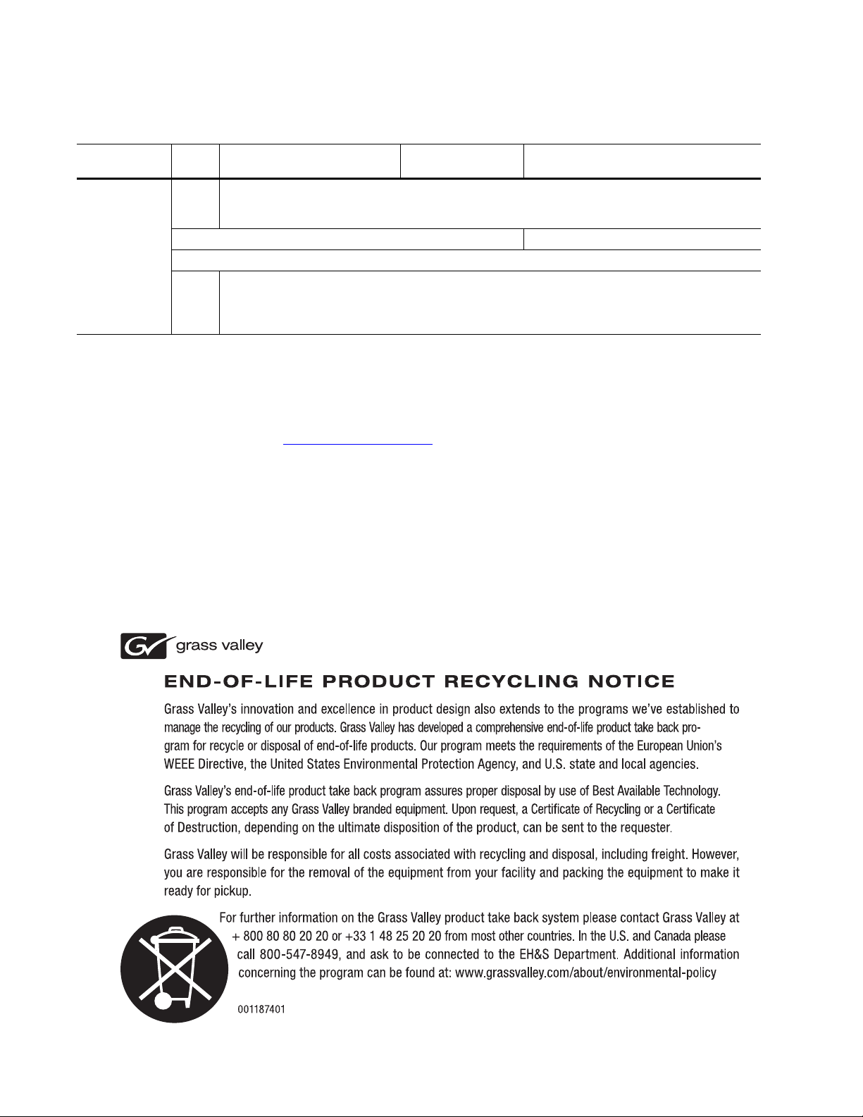
The Karrera Video Processor Frame is available in two sizes. The 8-RU standard size frame supports up to 4.5-ME systems. The 4-RU compact frame
supports 1-ME through 2.5-ME Karrera systems (
licensed boards present in the Karrera frame determines the number of
MEs available, as well as the number of video inputs, outputs, GPIOs and
Relay Tallies.
Figure 1). The number of
18 KARRERA — User Manual
Page 19
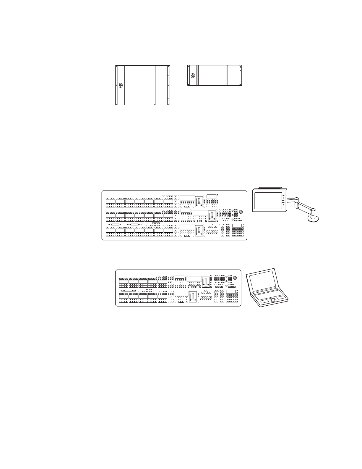
Figure 1. Karrera Video Processor Frames
Karrera 8-RU
Video Processor Frame
Karrera 4-RU
Video Processor Frame
Optional Touch Screen
Karrera Menu Panel with
Fanless PC
Menu Panel
Articulated
Arm
8623266_02_Krr
Karrera 3-ME 35 Control Panel
Karrera Control Surfaces
A Karrera control surface typically consists of a Control Panel and a Menu
application. Representative Karrera control surfaces are shown in the fol
lowing illustrations.
Figure 2. Karrera 3-ME 35 Control Surface
Overview
-
Figure 3. Karrera 2-ME 25 Control Surface
Karrera 2-ME 25 Control Panel
Karrera Menu Application
The Karrera Menu application software provided with every Karrera
system can be run on a standard PC. This software accesses all the function
ality of a Karrera system, permitting mouse and keyboard control from a
laptop, or remote control from any location on the network.
Karrera Menu on PC
(Customer Supplied PC)
8623266_03_Krr
-
KARRERA — User Manual 19
Page 20
Section 1 — Introduction
8623266_05_Krr
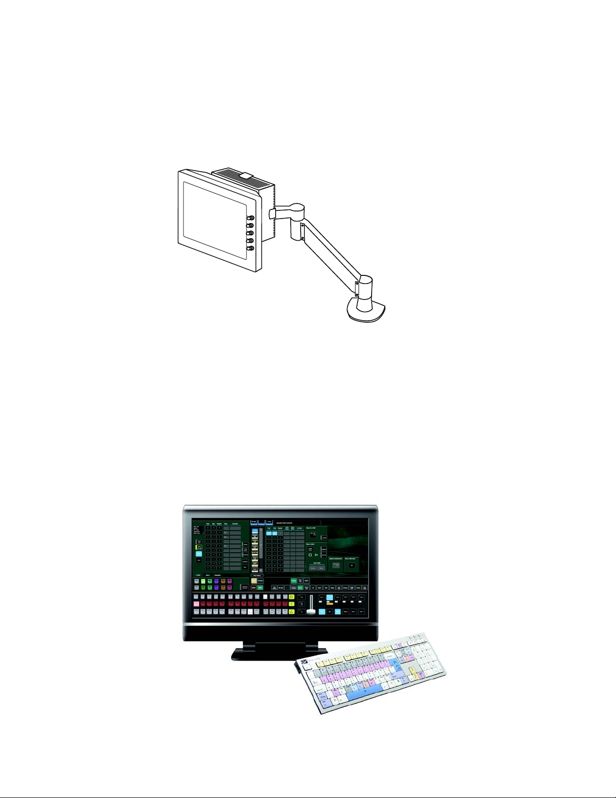
Touch Screen Menu Panel Option
A hardware Karrera Menu Panel is available as an option, which features a
wide format 15 in. touch screen display. An articulated arm is also
included, offering a wide variety of installation options (
Figure 4. Menu Panel with Articulated Arm
Figure 4).
The Menu Panel has a standard VESA-75 hole pattern and M4 threads,
compatible with this and many other mounting devices. The Menu Panel
also has four USB ports, two on the right side edge of the panel and two on
the back for keyboard and mouse (wired or wireless are supported).
A fanless PC, running Windows OS, is available which mounts behind the
Menu Panel.
Soft Panel (KSP) Option
Figure 5. Soft Panel Application
20 KARRERA — User Manual
Page 21
Karrera System Examples
Karrera 2-ME 25 Control Panel
Karrera 4-RU
Video Processor Frame
Karrera Menu on PC
(Customer Supplied PC)
The KSP is an optional 1-ME Soft Panel GUI which provides direct control
of switching crosspoints, recalling effects and macros together with an inte
grated version of the Karrera Menu application. A customized PC keyboard is included with the option for users who like quick cut and mix
action from a hard-button interface. The KSP can be used as an adjunct to a
main panel, providing a second seat (second control surface) in a Suite, or
as the only control surface for a second Suite.
The KSP GUI application is designed to run on a PC platform. The screen
must be 1920x1080 resolution or better (which is common in professional
video environments). A touchscreen is not required, but can be very useful.
The KSP software is included with the switcher application software. Purchasing the option provides a software license that enables the interface,
and includes a customized PC keyboard. The license activates an unlimited
number of KSP applications associated with a video processor frame.
Additional customized PC keyboards are also available for purchase.
-
Karrera System Examples
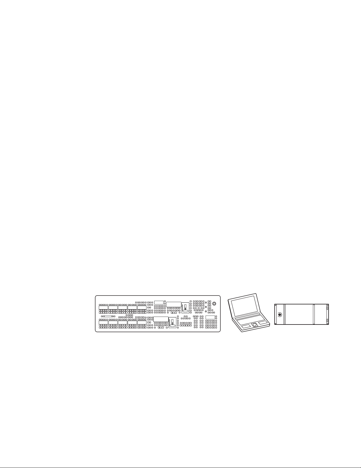
Basic Single Suite System
A basic Karrera system consists of a Control Panel, a Karrera Menu application running on a PC, and a Video Processor Frame. The Control Panel
and Menu application make up a control surface associated with that frame
Figure 6).
(
Figure 6. Karrera Single Suite Compact Frame Example
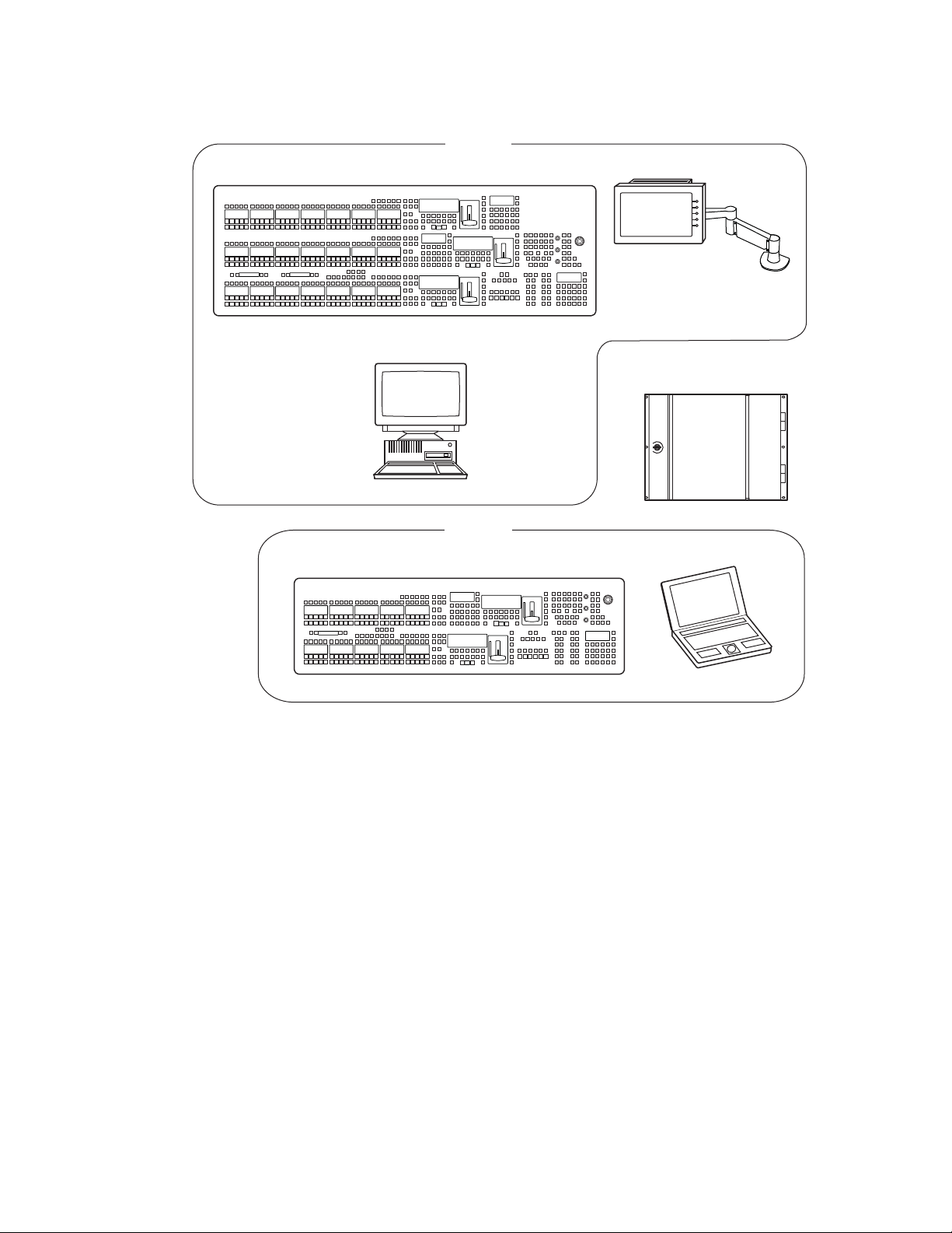
Multiple Suites and Control Surfaces
KARRERA — User Manual 21
A Karrera system can be subdivided into two suites, if desired, each of
which can have two control surfaces. Hardware resources in the Video Pro
cessor Frame can be assigned to an individual suite during configuration,
essentially creating two separate switchers from one Karrera system
(
Figure 7).
-
Page 22
Section 1 — Introduction
Optional Touch Screen
Karrera Menu Panel with
with Fanless PC and
Articulated Arm
8808_02
Karrera 3-ME 35 Control Panel
Suite 1
Karrera 2-ME 25 Control Panel
Shared Karrera 8-RU
Video Processor Frame
Karrera Menu on PC
(Customer Supplied PC)
KSP 1-ME
Soft Panel Option
(Customer Supplied PC)
Suite 2
Figure 7. Karrera Multi-Suite Standard Frame Example
22 KARRERA — User Manual
Page 23

User Setups and Preferences
Introduction
The Karrera Control Surface allows you to customize how you work and
how you save your switcher settings. You can create personalized user
setups and suite preferences that determine the look and operational char
acteristics of the Control Surface. User setups and preferences can all be
saved and transported on removable media (see File
page 39).
Some configurations will require setup in the Engineering menus as well.
Detailed descriptions of the Engineering menus are available in the
Karrera Installation & Service Manual.
This section will provide you with information about setups and preferences for basic Karrera operations. For more advanced setups and operation see Advanced Operations on page 217.
Section 2
-
File Operations on
Button Mapping
Button mapping assigns video sources to source selection buttons (Source
Button mapping). Button mapping is also used to assign Aux buses to del
egation buttons (Aux Delegate mapping). This allows you to customize the
Control Panel and configured Remote Aux Panels to meet your individual
needs. Button mapping settings are included as part of Panel Preferences,
and can be saved and instantly loaded for use at any time (see
tions on page 39).
Button mappings of the Control Panel are set at the factory before shipment
to the settings listed below.
KARRERA — User Manual 23
File Opera-
-
Page 24
Section 2 — User Setups and Preferences
There are four source button delegation levels with Karrera. Tab le 1 shows
the source to button mapping for the 1st (unshifted) and second levels for
a 35 button 3-ME system.
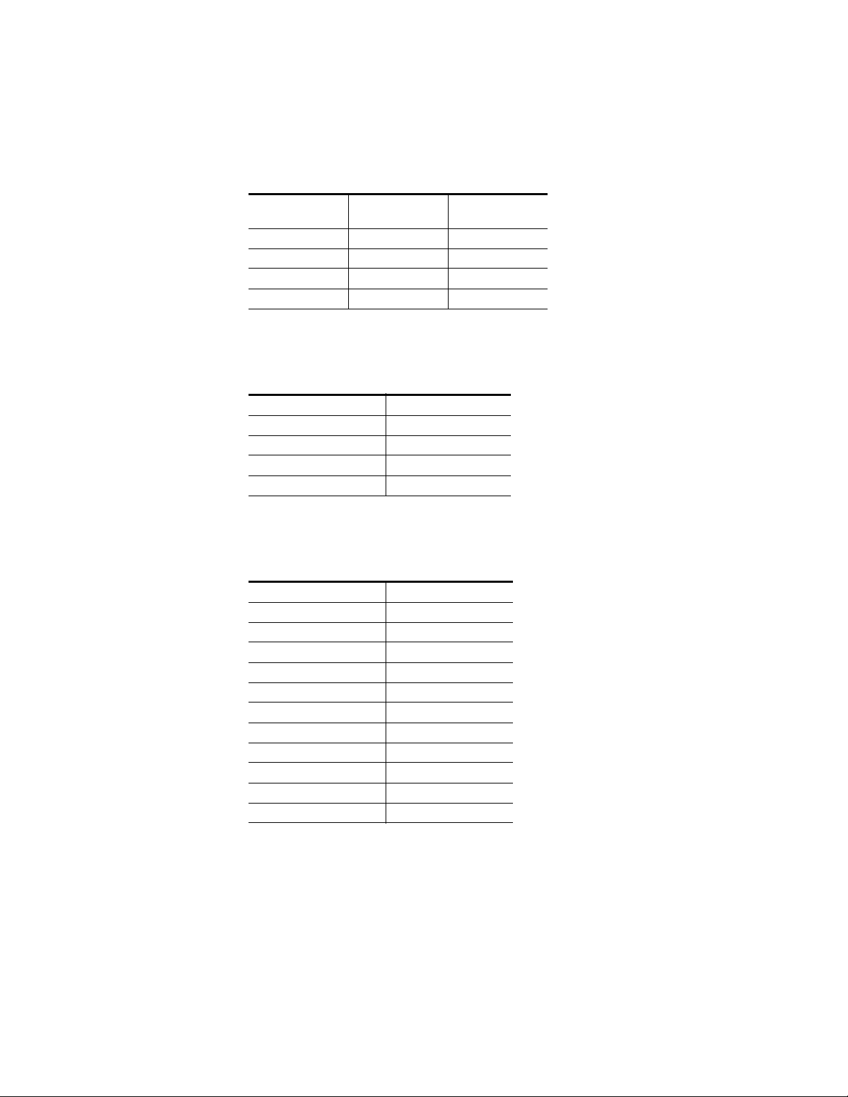
Table 1. 3-ME Factory Configured Source to Button Mapping 1st and 2nd Levels
Panel Button
Buttons 1-28 Source 1 - 28 Source 29 - 56
Button 29-32 M1 A - M4 A M1 C - M4 C
Button 33,34 Shift, Shift Shift, Shift
Button 35 Delegate Delegate
1st
(unshifted)
2nd
Ta bl e 2 shows the 3rd shifted level.
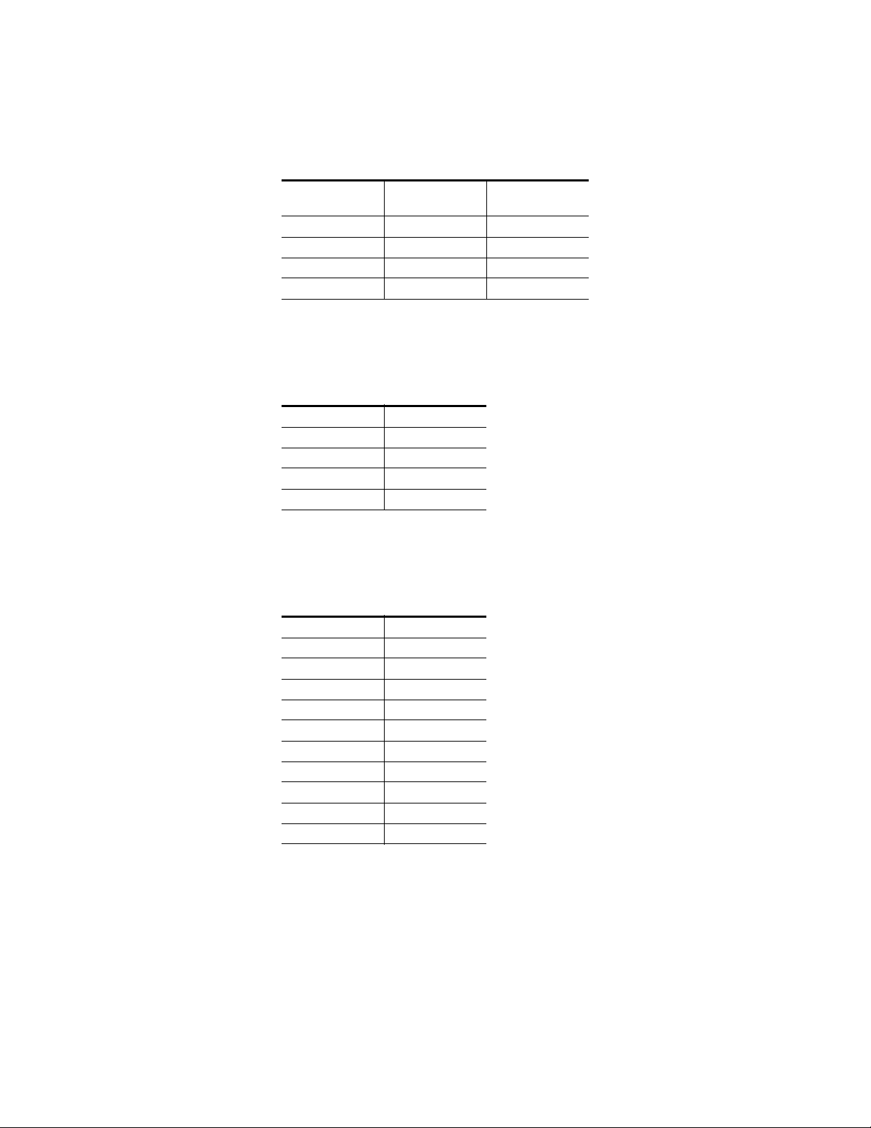
Table 2. 3-ME/35 Factory Configured Source to Button Mapping 3rd Level
Panel Button (35) 3rd
Buttons 1-28 Source 57 - 84
Button 29-32 M1 B - M4 B
Button 33,34 Shift, Shift
Button 35 Delegate
Ta bl e 3 shows the 4th shifted level.
Table 3. 3-ME/35 Factory Configured Source to Button Mapping 4th Level
Panel Button (35) 4th
Button 1-12 85-96
Button 13-18 IS 1 - IS 6
Button 19 eDA
Button 20 eDC
Button 21-24 Pg A - Pg - D
Button 25 Blk
Button 26 Test
Button 27,28 Bg 1,Bg 2
Button 29-32 M1 D - M4 D
Button 33,34 Shift, Shift
Button 35 Delegate
24 KARRERA — User Manual
Page 25
Button Mapping
Ta bl e 4 shows the source to button mapping for the 1st (unshifted) and
second levels for a 25 button 2ME system.
Table 4. 2-ME/25 Factory Configured Source to Button Mapping 1st and 2nd Levels
Panel Button (25)
Button 1-18 Source 1 - 18 Source 19 - 36
Buttons 19-22 M1 A - M4 A M1 C- M4 C
Button 23, 24 Shift, Shift Shift, Shift
Button 25 Delegate Delegate
1st
(Unshifted)
2nd
Ta bl e 5 shows the source to button mapping for the 3rd level for a 25 button
2ME system.
Table 5. 2-ME/25 Factory Configured Source to Button Mapping 3rd Level
Panel Button (25) 3rd
Button 1-18 Source 37 - 54
Buttons 19-22 M1 B- M4 B
Button 23, 24 Shift, Shift
Button 25 Delegate
Ta bl e 6 shows the source to button mapping for the 4th level for a 25 button
2ME system.
Table 6. 2-ME/25 Factory Configured Source to Button Mapping 4th Level
Panel Button (25) 4th
Button 1,2 Source 55,56
Buttons 3-8 IS 1 - IS 6
Buttons 9,10 eDA,eDC
Buttons 11-14 Pg A - Pg D
Button 15 Blk
Button 16 Test
Buttons 17,18 Bg 1,Bg 2
Buttons 19-22 M1 D - M4 D
Button 23, 24 Shift, Shift
Button 25 Delegate
Note When you map a Shift button, that button will be mapped in the same location
across all Shift Levels.
If a Karrera system’s NV memory is cleared, local panel button mappings
will revert to the factory defaults shown above.
KARRERA — User Manual 25
Page 26
Section 2 — User Setups and Preferences
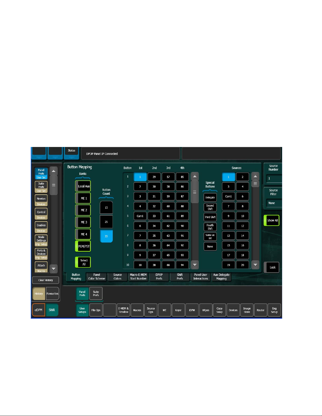
Source Button Mapping
On the Karrera system, each bank on the Control Panel (Source Select areas)
can have its own independent source-to-button mapping, if desired, as well
as each Remote Aux Panel. Typically button mappings on the Control Panel
are set the same, for operating simplicity. However, in some situations indi
vidual bank mapping can be advantageous. For example, on a show with a
large number of sources you can place all the DDR and VTR sources on one
bank, all the cameras on another bank, etc., and then have direct access to
any desired source. If you use this feature, source names should be defined
for all sources on all banks so the different sources can be identified.
The Button Mapping menu is accessed by touching User Setups, Panel Prefs,
Button Mapping (Figure 8).
Figure 8. Button Mapping Menu
-
The Banks delegation buttons (Figure 8) are used to select the device to be
mapped.
26 KARRERA — User Manual
Page 27

Local Panel Source Button Mapping
The Karrera Control Panels are considered local panels. Local panel button
mapping can be defined the same for all the banks at once, or you can select
individual local panel banks to map differently.
1. Touch the labeled Bank button(s) of the banks you wish to map
Figure 8). You can select one, some, or all of the banks to be mapped.
(
Notice that a Select All button is available below the list of bank buttons.
2. Scroll the Button list in the central pane and touch the bank source
button to be mapped in the center pane.
3. Scroll the Sources list on the right and touch the desired Karrera source
in the right pane. As the mappings change, the names of the different
sources will appear on the source name displays on the Control Panel.
4. Repeat Step 2 and Step 3 until all the bank buttons have been mapped.
Remote Aux Panel Source Button Mapping
Button Mapping
Note Remote Aux Panels must be installed and configured before their buttons can
be mapped. Remote Aux Panels assigned to a control surface can only be
configured when the Menu Panel is accessing that control surface. See the
separate Karrera Installation & Service Manual for Remote Aux Panel configuration procedures.
KARRERA — User Manual 27
Page 28
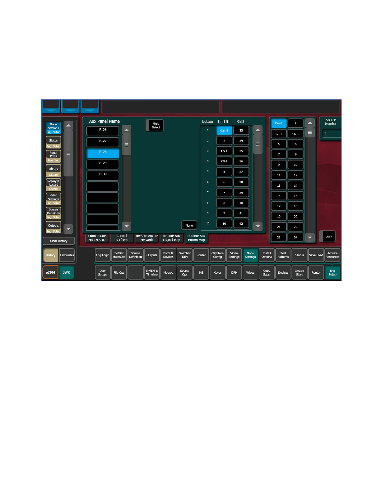
Section 2 — User Setups and Preferences
The Remote Aux Button Map menu is accessed by touching Eng Setup,
Node Settings, Remote Aux Button Map (Figure 9).
1. Individual Remote Aux Panels are selected by touching the buttons in
the left pane. Select the
Figure 9. Remote Aux Panel Button Map Menu
Multi Select button for group selection (Figure 9).
2. When multiple Remote Aux Panels are selected, changing a button’s
mapping applies that individual button’s mapping to all the selected
Remote Aux Panels.
3. Use the same button mapping procedure (page 27) to map the source
buttons on the Aux panel. Select the Aux source button in the central
pane, then select the Karrera source in the right pane.
Note Button mapping settings for Remote Aux Panels assigned to a Control
Surface are saved to the Panel Prefs configuration file. Button mapping settings for Independent Remote Aux Panels are saved to the Eng Setup configuration file.
28 KARRERA — User Manual
Page 29
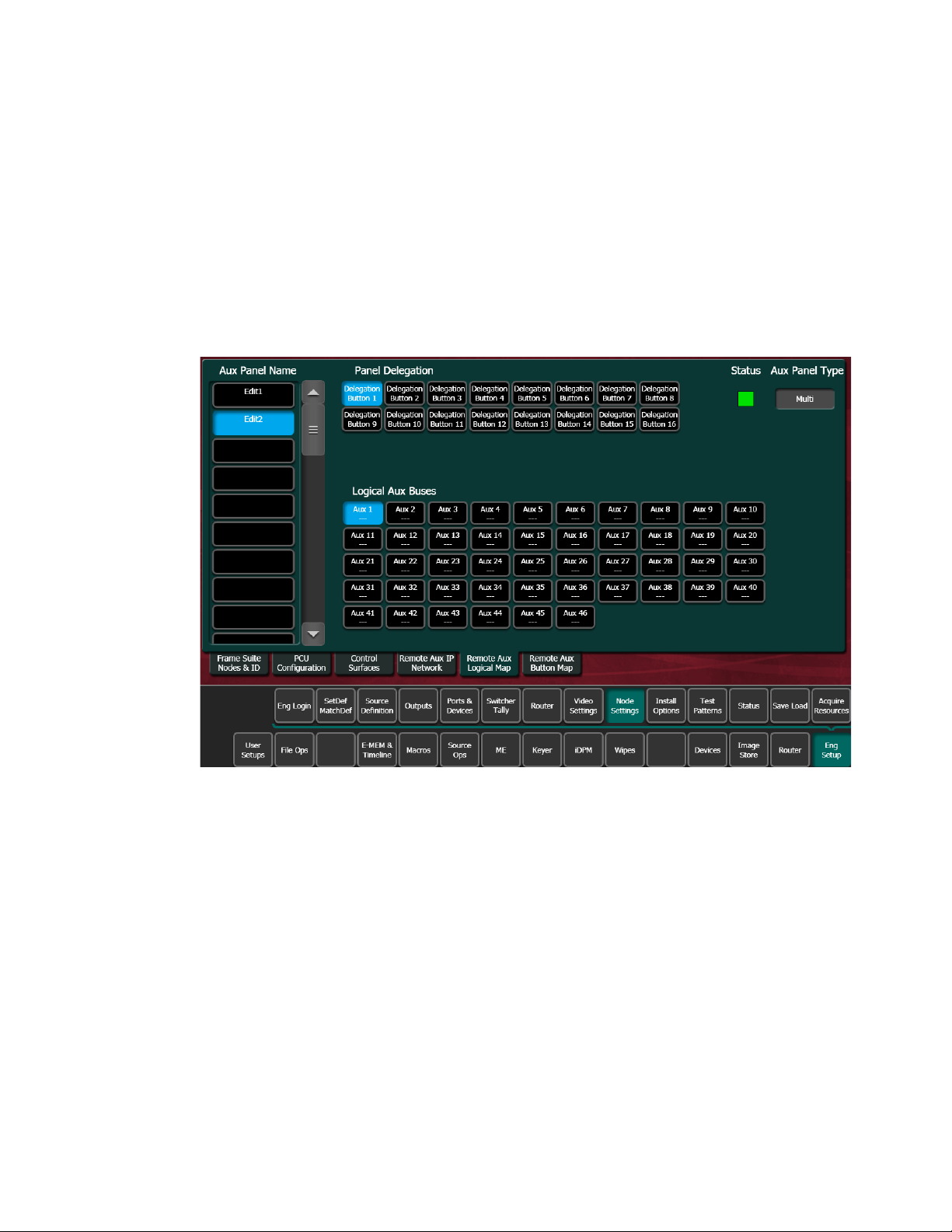
Aux Bus Delegation Button Mapping
Map Remote Aux Panel Delegation Buttons
On multiple destination Remote Aux Panels, delegation buttons are used
to select which Aux bus is delegated for control by that panel. You map
Remote Aux buses to delegation buttons using the Eng Setup, Node Set
tings menu, accessed by pressing Eng Setup, Node Settings, Remote Aux Logical
Map
(Figure 10).
Figure 10. Remote Aux Bus Delegation Button Mapping Menu
Button Mapping
-
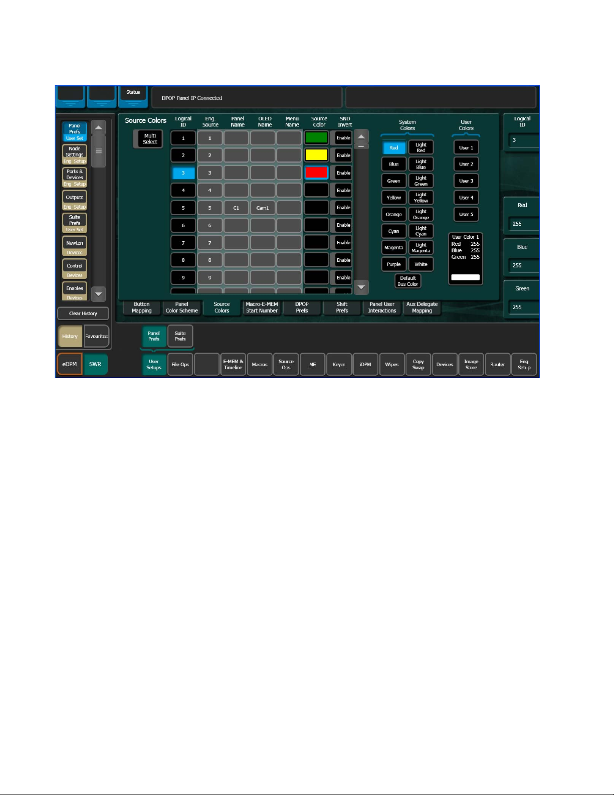
Source Colors
1. In the Panel Delegation pane, choose the Remote Aux Panel to
configure. Only one Remote Aux Panel can be selected at a time.
2. In the Logical Aux Buses pane, select the Aux Bus delegation button
you wish to map.
Note Button mapping settings for Remote Aux Panels are saved to the Eng Setup
configuration file.
The Control Panel sources can be changed from the Control Panel color
scheme to display user-defined colors (red, green, blue, light red, light
green, cyan, magenta, etc.). For example the operator could set user defined
colors for each camera as shown in
Figure 11 for quick reference.
KARRERA — User Manual 29
Page 30
Section 2 — User Setups and Preferences
Figure 11. Source Colors Menu
Assign Source Colors
1. To uc h User Setups, Panel Prefs, Source Colors to go to the Source Colors
menu (
2. Select the Logical ID of the desired source (use Multi-Select button for
multiple selections).
3. Select the desired color in the System Colors pane.
4. Selecting the Invert button displays dark text over a colored background
in the Source Select Area display OLEDs (default is colored text over
dark background).
Bus Delegate and Shift Button Source Colors
Source Colors can be configured for Bus Delegate and Shift buttons, in the
User Setups, Panel Prefs, Source Colors menu (
Figure 11).
Figure 12).
30 KARRERA — User Manual
Page 31

Figure 12. Source Colors Menu, Bus Delegate and Shift Button Configuration
Button Mapping
Assign User Colors
The User Color buttons allow you to create custom colors for sources
Figure 13). You can change the button color for one source or several using
(
the Multi-Select button for each button (1-5).
KARRERA — User Manual 31
Page 32

Section 2 — User Setups and Preferences
Figure 13. Source Colors Menu—User Colors
1. To uc h User Setups, Panel Pref to go to the Source Colors menu (Figure 11).
2. Touch a User Colors button User 1-User 5.
3. Adjust the User Color using the Red, Blue, Green data pads
Figure 11, right).
(
4. Select the Logical ID of the desired source (use Multi-Select button for
multiple selections).
For User-defined colors, see the User Color pane located below the User
Colors buttons when adjusting color with the data pads or soft knobs.
User-defined colors can be saved as part of a Show file.
32 KARRERA — User Manual
Page 33

Source Patching
Source Naming Background Information
Facility engineers need to know the exact routing of all the video signals
connecting all the devices they are responsible for. These engineers need to
be able to identify video signals in a way that will help them connect
devices properly. Production personnel, on the other hand, are interested in
the content they work with for their shows, and are generally not con
cerned about which individual device or routing path is used to make those
signals available. They just need a way to identify the content and access it
when they need it. To support these differing needs, two source naming
mechanisms are available on Karrera systems.
Engineering Names, Eng IDs, and Logical IDs
Engineering names are intended to identify a source as it applies to a specific facility. In a truck, for example, cameras may be hard wired to the production switcher and might be given Engineering names 1, 2, and 3. Names
like Patch
Engineering names are entered in the Eng Setup Source Definition menu,
as described above. Engineering source IDs are numeric only, and are avail
able on data pads and scroll knobs for quick selection. The Karrera system
also has logical IDs, that can be used for source patching, as explained later.
14 or Rtr 5 may be used for inputs that are patched or routed.
Source Patching
-
-
Alternative Source Names
Alternative names can be assigned to sources for the convenience of production personnel. For example, you may give the cameras menu names
that include the operator (C1
operator names from the OLED names to show C1, C2, and C3 in larger
characters. These alternative names are entered in the Source Patch menu.
The Source Patch menu (Figure 14) has three editable columns for defining
up to three alternative names:
A Panel Name is limited to four characters, to fit the space available on the
Control Panel’s Transition Area. This name is only displayed on the Control
Panel.
An OLED Name appears only on the Source Name Displays on the Control
Panel. Up to eight characters are displayed.
A Menu Name is limited to eight characters, and appears on all the Karrera
menu application screens except Engineering Setup menus, which always
display engineering IDs or names.
Bob, C2 Phil, and C3 Bill), but remove the
KARRERA — User Manual 33
Page 34

Section 2 — User Setups and Preferences
Multiple Suites and Source Names
Different sets of these alternative source names are defined for each Karrera
suite. Ensure the Karrera Menu Application you are using is logged into the
correct suite (
be used by both Karrera suites, however.
Name Display Hierarchy
If a source’s engineering name is left blank, the Eng ID number will be
used. If no alternative names are defined for that source, then that Eng ID
number will appear on all the Karrera system displays.
If an engineering name has been entered (see Karrera Installation & Service
Manual) then the engineering name will be displayed on all the Karrera
system displays, including menus. Engineering names will be truncated to
the character limits of the display, starting with the first character.
For alternative names entered in the User Setups, Suite Prefs, Source Patch
menu (
Figure 14), the following rules apply:
Eng Setup, Eng Logon). The same set of engineering names will
For the three editable columns: Panel Name, OLED Name, and Menu Name, if any
of the three are left blank for that source, the first name to the left appears
in that display on the system (if all three are left blank, the name in the Eng.
Source Column is displayed). For example, if an alternative name is entered
in the OLED Name column for a source and the other two columns remain
blank, the Menu Name takes the OLED Name (OLED Name being first to
the left of the Menu Name) but the Panel Name takes the Eng. Source
column’s name (first name to its left). If names are entered in all three alter
native name columns, each area of the system displays the name entered in
each column of the Source Patch menu (
Figure 14).
-
34 KARRERA — User Manual
Page 35

Figure 14. Source Patch Alternative Source Names
Transition Area
Blank Menu
Name displays
OLED Name,
first to the left
Menu Source
Lists
Source Patching
It is a good practice to create the least number of names possible. This
ensures consistency in the various displays and reduces the time needed to
enter and edit the names. If you can create short engineering names that
work for both the production staff and engineering, complete naming con
sistency is assured. However, this level of simplicity is probably only feasible at a fixed installation where all the shows use the same source names.
When multiple names are created, try to keep the first four characters
unique, and make different names for the same source similar for ease of
recognition.
Source Patch Feature
The Karrera system provides a way to map engineering source IDs to
logical IDs, using the Source Patch feature. By default this mapping is oneto-one, but this feature can be used to quickly set up production elements
for use in a different facility. For example, a show’s effects, DDR clips, and
taped material may have been built in one production truck with one set of
devices, but the next show is scheduled for a different truck. Previously, to
use effects in the other truck the Technical Director (TD) would need to edit
the engineering source definitions in the new truck so they exactly matched
the old truck. By remapping the engineering sources of the devices in the
new truck to the logical sources used to build the effects, all the effects can
be used without having to edit them. Source Patching can also be used to
-
KARRERA — User Manual 35
Page 36

Section 2 — User Setups and Preferences
quickly swap out a defective device during a show without having to
reconfigure the engineering sources. In this case logical names seen by the
production personnel would be identical for that content, even though the
actual device playing the material changed.
Note Source Patching is the bridge between engineering sources and logical
sources. Both TD and EIC should make reference to this menu when
resolving source issues. The mechanism is similar in concept to a physical
patch panel. Effects and all source selections are based on logical sources.
Tally and associations with external devices are based on engineering
sources.
Logical Sources
The Source Patch menu scrolling list has more Logical IDs than physical
inputs. These can be used to permit alternative processing of the same
incoming signal. For example, the same camera input can be assigned to
two Logical IDs, and one of these Logical sources can be given a Source
Rule that can be cut on Key 5, and the other be given a Source Rule that cuts
on Key 6. Selecting these different versions of that same source would auto
matically apply or clear the keys, as needed.
-
Using Source Patching for Effects Portability
Source patching makes it possible to build effects on a Karrera system in
one facility or truck, and then use those effects on a different Karrera
system at another facility that has different Engineering source configura
tions. Building a Source Patch table prior to effects creation simplifies the
migration of effects between facilities.
Plan out the sources you will use for a show, even ones that may not exist
on the system where you are creating the effects. Build a list of Logical
sources in the Source Patch menu without regard to the currently associ
ated Engineering sources. After the list is built, map one of the facility’s
existing Engineering sources to each Logical source. If physical devices
don't exist for some planned sources, substitute a dummy Engineering
source. You can then build your effects and verify that they run properly.
When you are satisfied with the effects, save the Suite Prefs and E-MEM
effects
files into that Karrera system. Do not load the Eng Setups of one facility into
the other, as this will overwrite that facility’s existing Engineering configu
ration.
Once the Suite Prefs and effects are loaded at the new facility, go to the
Source Patch menu and map the appropriate Engineering sources of the
new facility to the original list of Logical sources. Your effects should now
run as previously designed without having to edit or rebuild them. When
satisfied the effects run correctly at the new facility, save that Suite Prefs
under a different name for use the next time you use this facility. Do not
you created to USB Memory Stick. At the new facility, load these
-
-
-
36 KARRERA — User Manual
Page 37

overwrite the original Suite Prefs, as you will need it when you return to
the original facility.
Source Patching Procedure
1. Tou ch User Setup, Suite Prefs, Source Patch to go to the Source Patch menu
(
Figure 15).
Figure 15. Source Patch Menu
Source Patching
2. Select the Logical ID of the source you wish to change by either:
• Touching the Logical ID data pad (far right of menu) and entering
the Logical ID number.
• Scrolling through the Source Names list (scrolling list, left side of
menu) with the scroll bar. This scrolls the list without changing the
current selection. When the desired source appears on the menu,
touch its Logical ID button to select it (Figure 15).
KARRERA — User Manual 37
Page 38

Section 2 — User Setups and Preferences
3. If you wish, you can give sources alternative names in the Source Patch
menu in the following ways (
• Panel Name —Source will appear in the Transition and Multi-Function
area with this name,
• OLED Name (SND Name column)—Source Name Display will appear
in mapped ME/PGM PST Source Select areas and the Multi-Function
area with this name (see Alternative Source Names on page 33).
• Menu Name (Menu Name column)—Source will appear with this
name in the menus only,
4. If you wish to change the source patching, select an Engineering source
to be associated with the currently selected Logical source with the
Engineering Source data pad or by scrolling the Engineering Source IDs
Button pane (
on page 36.
Figure 15):
Figure 15). See Using Source Patching for Effects Portability
Default Keyframe
Default Keyframe settings are applied when an empty register is recalled
and when the
E-MEM area (
• SPOP clears the working buffer of enabled levels to Default Keyframe,
•
The Default Keyframe menu is used to learn the current Karrera panel state
to the system’s Default Keyframe (and to set the Default Keyframe back to
factory settings). Individual settings for each MEs are stored in the Default
Keyframe, so different states can be saved for different MEs, if desired.
Note Individual Default Keyframe settings are saved for each Karrera ME.
CWB (Clear Wo rk in g Buffer) button is pressed in the Master
EMEM Edit, CWB button) of the Control Panel.
however it does not clear the source memory.
DPOP clears the working buffer of enabled levels to Default Keyframe
and clears the source memory to the default settings for sources
selected on enabled levels.
38 KARRERA — User Manual
Page 39

File Operations
The Default Keyframe menu is accessed by touching User Setups, Suite Prefs,
Default Keyframe (Figure 16).
Figure 16. Default Keyframe Menu
File Operations
To Learn a Default Keyframe:
1. Setup the entire Karrera Control Panel to the desired state.
2. Press the Learn button in the Default Keyframe pane.
Pressing the Set button overwrites the Default Keyframe with factory
defaults.
Note Save your current Suite Prefs, which includes the Default Keyframe settings
before resetting to factory defaults.
The Karrera system has a file browser. You can browse through folders on
the local Karrera menu hard disk, the Karrera Video Processor Frame, and
the entire network file hierarchy of mapped drives.
KARRERA — User Manual 39
Page 40

Section 2 — User Setups and Preferences
Features
The Karrera file browser supports the following features:
• Navigate through the Frame User Directory on the Video Processor
(System Storage menus) and access the Menu Panel and all mapped
network drives including USB Memory Sticks (Remote Storage menus),
• Save and Load Show, User Setup, Panel Memory, E-MEM, Macro,
Source Rules, Cues, e-DPM, R-MEM, and Eng Setup files,
Note Image Store file operations are performed in the Image Store menu.
• Organize collections of files as Shows,
• Sort files by name and type, and in reverse alphabetical order,
• Create new folders,
• Copy/Paste, and Delete files,
• Rename files and folders, and
Introduction
• Select multiple files.
Karrera system files are saved to the location that has been navigated to with
the browser, creating copies of the information currently in use by the
Karrera system. Files are copied from one location to another without
affecting the current operation of the Karrera system. File information is
loaded to Karrera system RAM, and this immediately affects the operation
and capabilities of the Karrera system.
File and load operations are available from various menus. The same basic
operating procedures are used at each location and each is divided into two
navigational areas; Local Storage and Remote Storage.
40 KARRERA — User Manual
Page 41

File Operations
File Type Extensions
Karrera files are named by the user when saved, and this name appears
below the icon. The extension for each Karrera system file type is listed in
Ta bl e 7.
Table 7. Karrera System File Extensions
Icon Example File Type Extension
Panel Prefs .GVC
.GVF
.GVJ
Suite Prefs .GVS
.GVZ
Source Mem .GVM
Eng Setup .GVE
.GVH
.GVN
E-MEM Reg .GVR
R-MEM Reg .GVY
Panel Memory Reg .PMEM
Cues Reg .GVB
e-DPM Reg .GVI
Image Store .KIF
Macro Reg .GVG
Source Rules .GVL
Show Folders .GVV
The extension is added to the file automatically when saved, but is not displayed as part of the file name itself. To prevent confusion, do not try to add
an extension to the file name when saving files.
Non-Karrera generated file icons show the file name with extension, and
displays the extension letters in the icon.
Karrera Drive Access
The Karrera File Operation menus can access directories located on the
Compact Flash in the Video Processor Frame (System Storage) and the
Menu Panel hard drive (Remote Storage). Local and network drives
mapped on the Menu Panel’s Windows system are also accessible (Remote
Storage). Standard Windows functionality automatically maps all local
drives during startup. Mapping network drives to a drive letter using the
Windows Explorer allows them to appear at the top of the File Operation
menus on that menu system.
File Storage Organization
The file browser gives you great flexibility for choosing and creating
storage locations for your files. Any number of folders can be created in
KARRERA — User Manual 41
Page 42

Section 2 — User Setups and Preferences
various locations. File folders and the files themselves can be named in any
manner. To prevent accidentally saving and loading incorrect files, your
facility should establish file storage and naming conventions and follow
them consistently.
The engineer in charge should create default Panel and Suite Prefs files that
are not to be modified by anyone, and shared by everyone. These can
provide a known starting point for users when they build their own pref
erence files.
Experienced users may want to create their own sets of preference files and
save only critical ones in the Frame User directory. Other files can be loaded
using the browser from any directory or be placed on a personal USB
Memory Stick.
Use the Show feature to manage groups of files routinely used together for
a particular production.
Save important files to the Menu Panel hard drive and a USB Memory Stick
for backup, clearly label each (perhaps including the date), and store them
in a safe place.
-
Utilities Pane Operation
Each File Ops menu category has a Utilities Pane, with buttons to perform
Copy, Paste, Delete and Create Folder operations and a Multi-Select toggle
button.
Copy/Pasting Files
1. Navigate to the directory containing the file to be copied, using the
Top Directory, Up Directory, and Open Selected (or double-click on the file
icon) buttons.
2. Select the file(s) to be copied (choose the Multi-Select button for multiple
files)
3. Touch the Copy button. A new pane with its own scroll bar will appear
to the right.
right-hand pane. Files can only be pasted to the new right-hand pane.
The Delete, Create
pane only, and are inactive during a Copy/Paste operation.
4. Navigate the right-hand pane to the desired directory, using its
navigation buttons.
Top, Up, and Open navigation buttons will also appear for the
Folder, and Rename functions apply to the left-hand
5. Touch the Paste button. A message indicating the file is being copied
will be displayed, and when finished the right-hand pane will close.
42 KARRERA — User Manual
Page 43

Note Use clear naming conventions and logical directory structures when creating
Delete Files
1. Navigate to the directory containing the file(s) to be deleted, using the
2. Touch the file icon(s) to highlight it.
3. Tou ch t he Delete button.
Create Folder
1. Tou ch t he Create Folder button.
2. Enter the folder name in the pop-up keyboard.
3. Tou ch Enter.
File Operations
folders and renaming files so you can reliably reload the correct versions of
these files when you need them.
Top Directory, Up Directory, and Open Selected (or double-click on the file
icon) buttons.
Rename Files
1. Navigate to the directory containing the file to be renamed, using the
Top Directory, Up Directory, and Open Selected (or double-click on the file
icon) buttons.
2. Touch the file icon to highlight it (only one file can be renamed at a
time).
3. Tou ch t he Rename button.
4. Enter the new file name in the pop-up keyboard.
5. Tou ch Enter.
Multi-Select Button
The Multi-select button is useful for copying, pasting, loading, or saving
multiple files.
KARRERA — User Manual 43
Page 44

Section 2 — User Setups and Preferences
Show File Operations
The Show Files menu (accessed from File Ops, Show Files) is used to create,
save, and load Shows. A Show is a special collection of Karrera files that can
be managed as a group.
Touching the Create Show button opens a create show pane.
In this pane you enter the name of the Show (touch the Show Name data pad),
and if you choose, select which file types and choose a range of registers
that will be included in the Show file.
The Select All (toggle) button selects or deselects all the available file types.
Touching on a file type button selects or deselects that individual type of
file for saving/loading. Touching the data pads just to the left of the file
type buttons allows you to enter a range of registers, of that type, to include
in the show (
Touching the Create button saves the show into the currently selected directory. A pop-up panel displays the status of each file type as the Show file is
created.
Figure 17).
Figure 17. Create Show File Operations
44 KARRERA — User Manual
Page 45

CAUTION The Eng Setup button is off by default as ports and server IPs are unique so
1. Go to the File Ops, Show Files menu.
2. Select the Create Show button in the Show Create & Load pane (bottom-
3. In the Create Show pane, touch to select/deselect file types, or touch
4. Select the register data pad (left of each button) and enter a series or
5. Tou ch t he Create button in the Create Show pane.
Choose Load
Pressing Choose Load brings up a pane that allows you to see what files are
contained in the Show, and select which files to load. Buttons for files not
present are grayed out. By default all the files in the Show are selected for
load. The controls in this pane operate the same as the Create Show, except
the
File Operations
transferring Show files from one location to another (including suites)
requires planning to prevent interruption.
center).
Select All button (e-DPM is an option, if not installed the button will
the
be inactive).
range of registers to be included in the Show file (the default is
Load button replaces the Create button.
all).
Specify the file types and ranges of files you wish to load, then touch the
Load button.
Turning on the Clear and Replace button removes all files and replaces them
so you can limit what is loaded to what is in the Show file and not a cumu
lative load/overwrite.
Update Show
Tou chi ng th e Update Show button brings up a pane that allows you to select
specific files within a show to update. Specify the file types and ranges of
files you wish to update, then touch the
the show will be overwritten with the current Karrera settings for those
items.
Note A best practice is to set the E-MEM range from 0-999 each time there is an
Load Show
Touching the Load Show button immediately loads all the files in the currently selected show into the Karrera system. This operation will overwrite
the existing settings that are currently being used. While the current work
buffer and video outputs will not be affected, other aspects of system oper
-
Update button. The selected files in
update, this will ensure that new registers are included (the same practice can
be applied to other file types).
-
KARRERA — User Manual 45
Page 46

Section 2 — User Setups and Preferences
ation (source mapping, source name displays, available effects, etc.) will
change depending on what files are being loaded.
CAUTION Be sure the Show contains appropriate files before you load a Show, espe-
cially if the system is currently on-air or the Show contains Eng Setup files.
Choose Load can be used to inspect the Show and select files before loading.
All Files Operations
The File Operations All Files menu is used for managing Karrera system
file storage. The menu is accessed from
Figure 18. File Operations Menu
File Ops, All Files (Figure 18).
46 KARRERA — User Manual
Page 47

User Setups File Operations
The User Setups menu is used to save and load Panel Prefs, Suite Prefs, and
Source Memory. Only these file formats are supported in this menu. The
menu is accessed by touching,
For Panel Prefs and Suite Prefs, you can select all (Select All button) or individual files to load in the Load Granularity pane (right). Access the Load
Granularity pane by touching the Panel Prefs or Suite Prefs mode button
Figure 19).
(
Figure 19. User Setups Menu
File Operations
File Ops, User Setups (Figure 19).
The User Setups menu is similar to the File Operations All Files menu, with
a file display pane on the left and some of the same navigation and action
buttons in the center.
Save Panel Prefs or Suite Prefs Files
1. Tou ch t he Panel Prefs or Suite Prefs button.
2. Select all or individual file types to save.
3. Navigate to the desired destination directory and/or create a new
folder for the file using the buttons in the File Operations pane.
KARRERA — User Manual 47
Page 48

Section 2 — User Setups and Preferences
4. Touch the File Name data pad and enter the name you wish the saved file
to have.
5. Touch the Save button.
Save Source Memory Files
1. Touch the Source Memory button.
2. Navigate to the desired destination directory and/or create a new
folder for the file using the buttons in the File Operations pane.
3. Touch the File Name data pad and enter the name you wish the saved file
to have.
4. Touch the Save button.
Load Panel Prefs, Suite Prefs, or Source Memory Files
1. Navigate to the directory containing the files you wish to load, using
the buttons on the lower left.
2. Select the file to be loaded.
3. Touch the Load button.
CAUTION The Load button immediately replaces information the Karrera system is cur-
rently using with the selected file information. When configuration files are
loaded, significant changes to Karrera system operation are possible.
Panel MEM, E-MEM, Macros, Cues, e-DPM, and Router MEM File Ops
These menus all function similarly and are used to save and load their corresponding register files. Each menu is accessed by touching, File Ops, then
the menu category:
Note The key difference in the above menus are the number of registers, for
example the E-MEM menu has 1000 register files while the Macro menu has
999, and Router MEM has 100, and so on. Keep this in mind when entering
registers.
Note Register files are named by their bank and register number. For example, the
filename for E-MEM register 5 in Bank 2 would appear as EMEM25. File
names consist of the bank and register appended with.GVR. It is important
that these files retain these names, as the number determines which register
will receive the data when files are loaded. In fact, register files saved locally
to the Frame:C drive cannot be renamed. If you try to rename an E-MEM file
on the Frame:C drive an error message will appear in the message area. If for
some reason an E-MEM file needs to be renamed, copy it to a local drive and
rename it.
Panel MEM, E-MEM, Macros, Cues, e-DPM, or Router MEM.
48 KARRERA — User Manual
Page 49

Each menu is similar to the other File Ops menus with a file display pane
on the left and the same navigation and action buttons in the center.
Each menu provides the Utilities pane (Copy, Paste, etc.) and the ability to
select all, individual, or a range of register files to be saved or loaded. In
addition, in the File Operations pane, you can enter a starting register
which allows you to save/load a register or range of registers to a different
register or range of registers.
Save Register Files
1. Navigate to the desired destination directory and/or create a new
folder for the file using the buttons in the File Operations pane.
2. Touch one of the three Save/Load Register mode buttons (center) and
a. To uch th e All button to select all register files, or
b. To uch th e Enter Reg(s) button then enter a register or range of
registers in the
c. Tou ch t he Select Reg(s) button then select register files in the file
display panel (touch
File Operations
Register data pad (right), for example 1-5,10,12, or
Multi-Select button for multiple selections).
3. Tou ch Save. The register or range of registers will be saved to the target
directory.
Load Register Files
Registers are loaded by using the same methods as above but by touching
the
Load button.
Loading to a Different Set of Registers
One additional method of loading registers is available, that permits
loading registers with an offset.
1. Navigate to the desired destination directory and/or create a new
folder for the file using the buttons in the File Operations pane.
2. Touch the Enter Reg(s) button then enter a register or range of registers in
the
Register data pad (right).
3. Tou ch t he Start Register (highlights green) button.
4. Enter the number of the first register into which you wish to load the
selected range of registers, then touch
Enter.
5. Tou ch t he Load button.
The range of registers will be loaded to the specified register number
shown in the
KARRERA — User Manual 49
Register data pad.
Page 50

Section 2 — User Setups and Preferences
Source Rules File Operations
The Source Rules menu is similar to the other File Ops menus, with a file
display pane on the left and some of the same navigation and action
buttons in the center.
Save Source Rules Files
1. Select the file(s) to be saved (choose the Multi-Select button for multiple
files).
2. To uc h Save.
Load Source Rules Files
1. Select the file(s) to be saved (choose the Multi-Select button for multiple
files).
2. To uc h Load.
50 KARRERA — User Manual
Page 51

Eng Setup Operations
The File Ops, Eng Setup menu is used to save and load engineering setups
information. Only this file format is supported in this menu. The menu is
accessed by touching
CAUTION The Load button immediately replaces information the Karrera system is cur-
Refer to the Karrera Installation & Service Manual for more information about
Eng Setup operations.
Figure 20. Eng Setup Save-Load Menu
File Operations
File Ops, Eng Setups (Figure 20).
rently using with the selected file information. When configuration files are
loaded, significant changes to Karrera system operation are possible.
KARRERA — User Manual 51
Page 52

Section 2 — User Setups and Preferences
52 KARRERA — User Manual
Page 53

Video Mix/Effects
Introduction
This section provides information about switcher features and functionality that directly affect video content (images), for example: modifying,
processing, routing, and manipulating images in space.
MEs and Keyers
An ME is a subsystem of a video production switcher that can create a composite of two or more pictures. An ME includes multiple source selection
buses and provides transition (mix and wipe) and keying capabilities on
the selected signals.
Section 3
Keyers are used to insert part of one picture into another to create a composite picture. Keying involves three signals:
• background,
• key cut, used to specify where to cut a hole in the background, and
• key fill, used to fill the hole in the background. The fill can be an
incoming video signal or it can be an internally generated matte.
A separate key cut input signal is not necessarily required for keying. For
example, a self key (also called a video key) uses the same input signal for
both key cut and key fill.
The Karrera system supports the following types of keys:
• Linear Key (fixed and adjustable)
• Luminance Key
• Preset Pattern
• Chroma Key (option)
The Karrera system also supports self keys and split keys.
KARRERA — User Manual 53
Page 54

Section 3 — Video Mix/Effects
Chroma Key Operating Notes
The Karrera system features chroma keyers with powerful controls. These
controls offer subtle adjustments to allow successful keying of difficult
subject matter (fine hair, smoke, translucent objects, etc.), and to overcome
some problems resulting from imperfect chroma key set coloring or
lighting. The Karrera chroma key also has an Auto Setup feature that can
create an excellent chroma key under most circumstances without the need
for manual adjustment.
The following information provides more detailed instructions on how to
set up a chroma key using the Auto Setup feature and use the manual con
trols in the Keyer menu.
Auto Setup
The first step of setting up most chroma keys is to use Auto Setup. Auto
Setup automates the first steps to achieving a chroma key. Auto Setup per
forms the following:
-
-
• Calculates primary suppression Hue and Luminance.
• Sets primary suppression Selectivity and Chroma to defaults.
• Calculates Clip Low, and sets Clip Hi to default.
• Sets all the secondary suppression values to duplicate the primary suppression values, but turns secondary suppression off.
• Changes Opacity temporarily to 100% to permit an accurate backing
color sample, and then returns it to its original setting.
• Sets Key Position and Size values to default (0).
Two different Auto Setup algorithms are available, one for well designed
and lighted sets (
Reshape on). Depending on individual circumstances, additional manual
(
adjustments may be required after you use Auto Setup.
After an Auto Setup has been initiated, you can cancel it by pressing the
Auto Setup button again, but the chroma key will retain the default settings
imposed.
Reshape off), and the other for more challenging sets
Chroma Key Using Auto Setup
1. Press one of the Key 1-Key 4 Transition buttons on an ME to delegate the
keyer you wish to use.
2. Choose the selected keyer’s key bus that has the chroma key source and
the chroma key backing color.
3. Select the Chr as the key type in the Multi-Function area (source memory
may automatically select this key type).
54 KARRERA — User Manual
Page 55

MEs and Keyers
Reshape Off
4. Choose on the A bus the source that will be used to replace the backing
color of the chroma key source.
5. Go to the Keyer menu (double press the Keyer 1-Keyer 4 button for that
full keyer in the Keyer Transition area) and make sure
the keyer you are using (
Figure 21. Keyer Menu, Chroma Key Reshape Off
Figure 21).
Reshape is off for
6. Press the Auto Setup button in the Multi-Function area. Preview for that
ME will now display the chroma key source with a superimposed
cursor. The cursor actually represents a box of 16 x 16 pixels.
7. Use the joystick to position the cursor on the backing color. Select a
darker area, if one exists, to optimize the backing color suppression.
8. Press the button on top of the joystick. The chroma key will be set up
automatically using the average of the colors selected by the cursor box.
Because
Reshape was off, fine edges of the key will be preserved.
KARRERA — User Manual 55
Page 56

Section 3 — Video Mix/Effects
9. If this chroma key is acceptable, you are done. If set, lighting, or other
Chroma Key Using Auto Setup with Reshape
If the set is lit unevenly or has other problems, Reshape is available to help
solve the problem. A better alternative, if time permits, is to adjust the
lighting on the set to even out the backing color. This may improve the key
so that Reshape is not needed.
1. If you decide you must use Reshape, follow the Auto Setup procedure
2. If this chroma key is acceptable, you are done. If you are still not
conditions prevent the result from being acceptable, you need to decide
whether to adjust the chroma key manually or use Auto Setup with
Reshape.
• Manual adjustment permits retention of fine edge detail (see
Manual Chroma Key Adjustments on page 56). In particular, if there are
problems with translucent areas (hair, smoke) secondary suppression controls can be useful (see page 60).
• Auto Setup with Reshape produces a chroma key with harder
edges, but accommodates wider set variations (see below).
described above, but in
turn it on (its green indicator will illuminate). After selecting the
backing color area and touching the top button on the joystick, the
chroma key will be set up with coarser values better able to handle set
variations.
satisfied, you can fine tune the chroma key using manual adjustments.
Step 5 touch Reshape on in the Keyer menu to
Manual Chroma Key Adjustments
If the Auto Setup of the hue fails to provide a suitable chroma key, additional controls are available in the Keyer menu for fine tuning the key.
Chroma key manual set up consists of choosing the best set of compromises
to provide adequate detail and color fidelity to meet your needs. While
using this menu you need to view the chroma key scene on a monitor. A
vectorscope and waveform monitor can also be very useful when setting
up a chroma key. During set up you need to focus your attention on partic
ular areas of the foreground, background, and/or composite. The areas you
look at will change depending on the individual controls being used. The
FG Only and BG Only menu buttons can be used to remove extraneous picture
information, allowing you to view only those areas of the composite.
Chroma key set up procedures follow a recommended order, as indicated
by the numbered steps displayed on the menu. However, requirements can
vary depending on each individual scene. You may need to go back to
earlier steps and readjust previous settings to optimize the key. Under
standing what the chroma key controls do will help you decide what
adjustments are required for your individual situation.
-
-
56 KARRERA — User Manual
Page 57

Access Keyer Menu and Delegate Keyer
On the Menu Panel, touch Keyer, Mode. You can also double press the Chr
button in the Multi-Function area to access this menu. Delegate the keyer
you wish to set up on the left side of the screen, then touch the
Mode button (
Figure 22. Keyer Chroma Menu, Pri Suppress Controls
Figure 22).
MEs and Keyers
Chroma Key
Primary Suppression
Primary suppression is the most critical chroma key parameter, and the
easiest to set. Auto Setup should take care of this, but manual adjustments
can be made if desired. If primary suppression is set wrong, however, it will
be impossible to achieve a good chroma key with the other controls.
Primary Suppression should be set while looking at the foreground. Ideally
the backing color will appear as a small dot on the vector scope and a per
fectly flat line on the waveform display, but this never occurs due to set
lighting variations, shadows, etc. This means you will need to pick the best
suppression for the overall look of the key.
1. Touch the stage 1 Pri Suppress data pad, if necessary, to activate these
controls (
-
Figure 22).
KARRERA — User Manual 57
Page 58

Section 3 — Video Mix/Effects
2. Adjust Hue, Selectivity, Chroma, and Luma primary suppression to
eliminate the backing color.
• Hue can be set accurately with Auto Setup. Hue should center on the
primary color of the backing area of the foreground scene.
Depending on where
adjusting
Chroma suppression should be preset to 100% and Luma set to 0%.
Hue can then be tuned to remove the backing color.
Selectivity may need to be increased if there are colors in the fore-
•
ground image that are being suppressed.
low as possible without including colors that should not be suppressed. For example, when keying on green, a greenish yellow
shirt might be affected by the suppression. If so, adjust the selectivity high enough to reject that color. Too high a selectivity is one
of the classic causes of a noisy key. If the foreground subject is stationary, consider using a force mask instead of increasing selectivity.
•
Chroma suppression can be set accurately with Auto Setup. To
adjust, increase
dot on the vector scope move toward the center. You want to center
it exactly, so no chroma exists in the backing area. 100% chroma suppression is the correct setting for all chroma keys. At this point, you
will probably see a line through the center of the vector scope. With
increased selectivity, this line will become an arc.
Hue may not make any noticeable change on the scene.
Luma and Chroma primary suppression are set,
Selectivity should be set as
Chroma suppression and observe the backing color
Luma suppression adjustments may be necessary if shading is
•
visible in the backing area with
adversely affects the background image. Primary Luma suppression is hardly ever desired when Reshape is on. To adjust, increase
Luma suppression and observe the backing color move toward
black. You want to make the backing color just black. Increasing this
control too much will make the chroma key hard and noisy. When
not enough, highlights will be added to the background. Note that
incomplete luminance suppression is not necessarily bad. The highlights added to the background will match the shading on the
backing wall, adding natural shadows and perhaps eliminating the
need to add artificial shadows.
• All the above adjustments may need to be revisited later.
3. Another potential artifact of chroma keying is a tinting of the overall
foreground subject due to lighting splash from the backing color or lens
flare.
Flare Suppression adds a small amount of color to the entire
foreground image to cancel the splash or flare. Typically less than 2% of
the backing color is needed to neutralize the flare.
FG Only selected, or if the shading
58 KARRERA — User Manual
Page 59

Key Controls
The purpose in adjusting Clip Hi and Clip Low is to cause the proper hole to
be cut in the background. All areas of the backing color should be full back
ground while all areas of the foreground should make the background
completely invisible. The easiest way to do this is to observe the key signal
while making your adjustments.
The smaller the difference between Clip Hi and Clip Lo, the higher the keyer
gain. High gain amplifies noise present in the transition between trans
parent and opaque. The correct setting is with Clip Hi and Clip Lo set to just
barely achieve opacity and transparency, respectively
1. Touch the stage 2 Key Controls data pad to activate these controls. You can
2. Select Show Key in the Keyer menu (Figure 23) and look at the ME
Figure 23. Key Controls
MEs and Keyers
-
-
.
now manually adjust keyer clipping controls.
preview output on a picture and waveform monitor.
3. Adjust Clip Hi so that all areas of the foreground objects are white. If
Clip Hi is set too low (too far clockwise), much of the translucent areas
will be forced to be fully opaque, hardening the key and darkening the
transition area between background and foreground.
KARRERA — User Manual 59
Page 60

Section 3 — Video Mix/Effects
4. Clip Low can be set accurately with Auto Setup. Adjust Clip Low so that all
Note When adjusting clip levels, remember that areas on the edge of the fore-
5. Check the final results with Show Key off and the chroma keyer in normal
6. If the chroma key now looks good, you are done. If dark edges are
Reshape
Reshape is useful when shading variations exists in the backing color. A
better alternative, if time permits, is to adjust the lighting on the set to even
out the backing color. This may improve the key so that Reshape is not
needed. Reshape helps with backing color suppression at the expense of a
harder looking key with more noticeable edge artifacts.A drawback of
Reshape is loss of detail in the keyed edge. For example, smoke and hair in
the foreground will probably be lost.
areas of the backing color are black. If
counter-clockwise), translucent areas will be forced fully translucent,
hardening the key.
ground subject should show as shades of gray. Gray indicates areas of translucency, which is desirable in chroma keying.
mode (
hard, noisy key.
present, there may be too much primary
Clip Low may be set improperly. If adjusting these parameters fails to
solve the problem, you should consider activating the Reshape feature.
FG Only turned off). Note that incorrect adjustments can create a
Clip Lo is set too high (too far
Luma suppression or Clip Hi or
1. Touch the Reshape button to activate this feature.
2. Set primary Luma suppression to 0.
3. You can now readjust the Clip Hi and Clip Low controls if necessary to fine
tune the key as described above.
4. When Reshape is on, key resizing and positioning also become available
to clean up the key edges.
• Size narrows the key signal and can remove much of the blue or
green edge on the foreground subject.
Position moves the key signal left and right, and can be used to
•
reduce a color edge along only one side of the foreground.
Secondary Color Suppression
Secondary color suppression is intended to improve the color of translucent areas (e.g., glass or smoke) or fine detail near the edge of a foreground
subject (e.g., hair). These areas can be take on some of the backing color.
Much less secondary suppression will be needed than is used for primary
suppression, because the foreground color is only partially corrupted by
the backing color. Because there is a mixture of backing color and fore
-
60 KARRERA — User Manual
Page 61

MEs and Keyers
ground color, the secondary suppression Hue and the direction (Angle)
will be different from primary suppression. Primary suppression removes
the backing color, while secondary suppression corrects the color in trans
lucent areas.
Note If Reshape has been applied, it is unlikely enough edge detail will remain to
use secondary color suppression.
1. Touch the stage 3 Sec Suppress data pad and then touch the
Secondary Suppress button to activate this feature (Figure 24).
Figure 24. Sec Suppress Controls
-
2. Adjust secondary suppression Hue and Selectivity so that the translucent
area is affected, but opaque areas of the foreground are not. The final
hue will lie somewhere between the backing color (primary
suppression hue) and the uncorrupted foreground color.
• When making this adjustment, it is helpful to turn the secondary
Chroma Suppression to maximum, and the secondary Suppression Angle
to produce an unnatural color in the affected area. This makes the
changes to secondary suppression more obvious.
• Selectivity should be kept as wide as possible. You should only
narrow selectivity (increase its value) if you cannot avoid changing
opaque areas of the foreground.
KARRERA — User Manual 61
Page 62

Section 3 — Video Mix/Effects
3. Adjust the secondary Angle so that changing secondary Chroma
4. Decrease secondary Chroma suppression for the best match between
5. Increase secondary Luma suppression to balance lightness of the
6. Repeat secondary suppression Angle, Chroma suppression and Luma
Extra Chroma Key Controls
Additional chroma key controls are available by touching the stage 4 Extra
data pad (
ally activated by touching the labeled buttons.
suppression moves the color in the desired direction. You are trying to
match the color of the translucent areas to an opaque (uncorrupted)
area of the foreground subject.
corrupted (translucent) and uncorrupted (opaque) areas. Interaction
between secondary suppression Angle and Chroma suppression may
require repeating these adjustments.
translucent and opaque areas.
suppression for best results.
Figure 25). Coring, fringe, and shadow controls can be individu-
Figure 25. Extra Controls
Coring replaces any pixels in the luminance signal after primary suppression
that are below the adjustable threshold with black. This eliminates noise
62 KARRERA — User Manual
Page 63

resulting from incomplete suppression. While coring can improve some
keys, it can easily be over done. Coring thresholds much above black will
affect dark grays that are actually part of the foreground subject, making
the chroma key composite look unnatural.
Fringe is used to restore color to the gray portions of the foreground color
resulting from secondary suppression adjustments. This control is only
active when secondary suppression is on.
Shdw provides controls of shadows that fall on the backing. Shadow Clip and
Shadow Gain allow selecting the range of the luminance portion of the fore-
ground that produces a shadow. Shadow Density is an opacity control for the
shadow and adjusts how much shadow is added to the background.
Background Mattes
Background matte generators create colors and washes. These can be used,
for example, as the backgrounds for keys.
Background mattes cannot use the wipe pattern generators available to
keyer and wipe mattes, and cannot use Utility video as a wipe source.
Instead background mattes employ a simple dedicated wipe generator that
creates a single, straight line.
MEs and Keyers
Background matte control is available from the Control Panel (Multi-Function area, Matt button in the Home menu) and from the Keyer, Matte menu,
which provides additional background parameter controls.
1. Go to the Mattes menu by pressing Keyer, Mattes.
2. Tou ch t he BKGD button.
3. If not already selected, touch the Base Color data pad of the desired
Background (1 or 2). Use the top three soft knobs to adjust
Base Saturation, and Base Brightness of the base fill color (Figure 26).
Base Hue,
KARRERA — User Manual 63
Page 64

Section 3 — Video Mix/Effects
Figure 26. Matte Menu, Base Color Selected
Split Key
4. Touch the Wash On button at the bottom so its indicator illuminates to
create a wash matte.
5. Tou ch th e Wash Control data pad to bring up Offset, Softness, and Rotate soft
knob controls. If necessary, use the
wash edge visible on the screen. You can also turn on the
and then adjust the angle of the edge using the
6. Touch the Wash Color data pad to delegate the soft knobs on the right to
adjust
Because all background matte parameters are keyframeable, you can build
effects with constantly changing backgrounds using multiple keyframes.
Sometimes you may wish to use the key cut signal of one source with the
key fill or video signal of another source. For example, you may have a
Character Generator creating matte filled characters, but wish to use a dif
ferent signal to fill the characters. A split key is used to accomplish this.
On the Karrera system, the source select buses by default tally the key fill
signal.
Wash Hue, Wash Saturation, and Wash Brightness of the wash fill color.
Offset and Softness knobs to make the
Rotate button,
Rotate soft knob.
-
64 KARRERA — User Manual
Page 65

Keyer Priority
MEs and Keyers
To P erf or m a Spl it Ke y:
1. Touch Source Ops, MEs in the Karrera menu.
2. Touch the Cut signal data pad for the Keyer you wish to split
(highlights blue).
3. Select a source from the scrolling Source List (right) and touch that
source.
The ME Status display in the Transition area shows the source names of
any key cut signals.
Note Split Key will be shown in the Multi-Function area display.
Video switchers with only two keyers per ME use a simple key over/key
under mechanism to control the stacking of the keys. Only one key can be
located over the other. The Karrera system has six keyers per ME, so more
complex stacking is possible. Keys can be placed between other keys, using
key priority.
To Change the Current Keyer Priority:
1. Go to the Keyer-Priority menu in the Menu Panel by pressing Keyer,
Priority (Figure 27).
KARRERA — User Manual 65
Page 66

Section 3 — Video Mix/Effects
Figure 27. Keyer Priority Menu, Current Stack Selected
2. If not already set up, turn on the desired keys and arrange them so they
overlap, observing the Program monitor. This will make the changes in
key priority visible. For demonstration purposes, you can use four
preset pattern keys.
3. Select the keyer you wish to move in the stack in the Current column,
then use the
place the key in the desired location. The key priority order changes
immediately, as a cut.
Top, Move Up, Move Down, and Bottom buttons on the left to
To Transition Between Different Keyer Priorities:
Key priority transitions use a Current priority stack and a Next priority
stack. The transition occurs between the two stacks.
1. Press the Key Prior Transition Element button in the Transition area
(button row under status display, far left function button).
2. If not already set up, turn on the desired keys and arrange them so they
overlap, observing the Program monitor. This will make the changes in
key priority visible. For demonstration purposes, you can use four
preset pattern keys.
3. Delegate that ME for preview in the Preview button group on the
System Bar. This shows the end result of the transition (the Next
priority).
66 KARRERA — User Manual
Page 67

MEs and Keyers
4. Go to the Keyer-Priority menu in the Menu Panel by pressing Keyer,
Priority.
5. The current stack in the menu is automatically set to what is currently
being output. You can change the Current priority stacking order if
desired, as described on
6. Set up the Next priority stacking order, selecting the keyers in the Next
column and then using the
(
Figure 28). The new stack will be visible on the preview monitor.
Figure 28. Keyer Priority Menu, Next Stack Selected
page 66.
Top, Move Up, Move Down, and Bottom buttons
7. Select the type of transition, using the Mix, Wipe 1, or Wipe 2 buttons in
the Transition area. If you selected a wipe, go to the Wipes menu by
double pressing one of the
any modifiers to be used with the wipe.
8. Move the lever arm or press the Auto button in the Transition area to
perform the key priority transition. The transition is shown on the
Program monitor.
Wipe buttons, and then select the pattern and
KARRERA — User Manual 67
Page 68

Section 3 — Video Mix/Effects
Key Store
The following features are defaults for Key Store:
• Source Memory is always on.
• Source Memory is provided for each Key Store—Keyer mode and set-
• Key is black upon reset—If there is not a Key Store loaded, it will not be
Each full keyer can store two frames of memory; each frame containing
both Keyer Video (fill) and Key (cut), that together create the Key Store.
Each Key Store can save the use of other switcher resources. For example
instead of using an Image Store channel or another keyer, you could store
a station ID or a replay graphic (still) for a sports show in a Key Store and
switch the image within the keyer.
In the Keyer, Key Store menu (Figure 29), each Store has two frames, Frame
Store 1 and Frame Store 2. Each can ‘Grab’, ‘Store’, and ‘Use’ a still image
for a key source. So in addition to Live video, you have up to two fill/cut
images that can be interchanged on any full keyer source.
tings for the last use of the Key Store will be recalled.
placed on-air.
The fill and cut from Live, and Frame Store 1 and Frame Store 2 pages can
be used in any combination, for example you can use the fill from Keyer
Video Source, Frame Store 1 with the cut from Keyer Cutout Source, Frame
Store 2. You can even use the Live video from the Keyer Video Source and
the cut from Keyer Cutout Source, Frame Store
Each Key Store has Key Store source memory not controlled by the source
memory settings in Suite Prefs.
On power cycle or reboot, Key Stores will have to be reloaded with the
correct video. They default to black keyed with black which will not show
up on a monitor.
Key Store is E-MEMable and keyframeable.
1.
68 KARRERA — User Manual
Page 69

Figure 29. Key Store Menu
MEs and Keyers
Grabbing and Using a Key Store Image
The keyer settings are defined in the Eng Setup, Source Definition menu
where for example you can set a key to a Linear or Shaped Video. You will
need to define these parameters when creating a Key Store.
Note If not defined, the key will be full raster white.
You can ‘Grab’ both a video and key frame simultaneously by touching
either the
page, or you can touch a
Frame Stores (
Once you have grabbed fill and key images in Key Store, you can ‘use’ them
for the selected key source:
1. Touch the full keyer with which you want to use Key Store (Figure 29,
left).
2. Touch either the Use Live V&K, Use FS 1 V&K, or Use FS2 V&K to select the
Video and Key source image (
a. Touch the Keyer Video Source you want as fill.
Grab V&K 1 or Grab V&K 2 button, located below each Frame Store
Grab button for any of the four Video/Cutout
Figure 29).
Figure 29), or
b. Touch the Keyer Cutout Source you want as the key cut.
Show Key button—Shows the cut signal for the selected Key Store source.
KARRERA — User Manual 69
Page 70

Section 3 — Video Mix/Effects
Push to Preview button—Shows the current Key Store image on Preview.
Pattern Mix
The Karrera system can combine the complex wipe pattern generators (P1
and
To Create a Pattern Mix on PRI Wipe 1:
1. Double press the Wipe 1 button in the Transition area. This selects Wipe 1
2. Select the P1 pattern to be used by touching the Wipe Pattern button
3. Select the Pattern Mix data pad, this switches the Pattern tab on the right
P2), to create a wide variety of customized wipes.
as the next transition type, and also opens the Wipes menu with
PRI
Wipe 1 delegated for control.
between the
one of the displayed patterns in the Pattern tab on the right.
to the other generator; in this case P2 (to select the base wipe pattern
again, touch the Wipe Pattern button as in Step 2).
Pattern Mix and Generator/Border data pads, and then selecting
4. Touch the Mix data pad located below the Pattern tab. Additional
control buttons will appear at the bottom of the menu.
5. Delegate that ME for preview in the System Bar.
6. Press the Tra ns PVW button in the Transition area, and move the lever
arm part way. This will display the P1 pattern on preview.
7. Touch the delegation button in the Pri Wipe 1 column to delegate the
menu to control the Pri Wipe
8. Touch the Pattern Mix button so its indicator illuminates. The preview
monitor will now show the combined Mix
9. You can select the type of pattern mix with the Mix type buttons (Mix,
NAM +, NAM –). The NAM buttons are used for And or Or pattern mixing.
10. You can also adjust the amount each wipe pattern contributes to the mix
with the
the other pattern contributes only 25% to the final pattern.
Ratio control. At 50%, each pattern contributes equally. At 25%,
1 pattern generator.
1 and Mix 2 pattern.
70 KARRERA — User Manual
Page 71

iDPM Operations
Karrera has two types of DPMs (Digital Picture Manipulator) options avail-
able, iDPMs (Internal) that are available by floating license on the first four
keyers of each ME for a maximum of sixteen (on a 4-ME system) and
eDPMs (Extended), four combined or independent DPM channels that can
be mapped to separate source select buttons or delegated to any of the six
keyers on any ME (see
If any iDPM channels less than the maximum are licensed, then those iDPM
channels can be used on any of the first four keyers of an ME. For example,
if you only have two floating iDPM Channels licensed on a 2-ME system,
the two iDPM Channels can be assigned to two of Keyers 1-4 on one full ME
or one keyer on each of the two full MEs.
Note iDPMs and eDPMs are software options (and also hardware in the case of
iDPMs can be activated and controlled in the Menu Panel and the MultiFunction area. Most but not all of the functions are common.
iDPM Operations
eDPM Operations on page 111).
eDPM) and must be enabled in the Eng Setup, Install Options menu when
purchased.
Multi-Function Area iDPM Delegation
The Multi-Function area in the Karrera Control Panel can be delegated to
activate and control iDPM Channels. The Multi-Function Area can be del
egated in any of the following ways:
• Press any keyer button in the Source Select area (above the Source Select
buttons) of the desired ME,
• Press any keyer button in the Multi-Function Area (second button row
from the top), or
• Touch to select the ME in the
Turn on the Keyer iDPM
To turn on the iDPM for one or more keyers in the Multi-Function area,
either press a single keyer button (Key 1—Key 4) and then press the
On
button or press and hold down a keyer button while selecting additional
keyer buttons and then press the
Note The DPM button will also place the Multi-Function area into DPM mode.
-
ME, Mode menu in the Karrera menu.
iDPM
iDPM On button (Figure 30).
KARRERA — User Manual 71
Page 72

Section 3 — Video Mix/Effects
eDPMDPM
MEME
3
MEME
2
PGMPGM
MEME
4
MEME
1
iDPM
OnOn
MaMattete
Fillill
Auto
Se
Setupup
Videoideo
Key
Linin LumLum ChrChr
ShowShow
MenuMenu
Loc
3D
3D
Src
SpinSpin
X Y Z
Det
Ctr
Addv
Key
Pst
Ptn
Key
1
Key
2
Key
3
Key
4
Key
5
Key
6
Wipe
1
Wipe
2
Key
Wipes
es
Pri
Glob
Glob
Sec
Glob
Glob
ShdwShdw
DPMDPM
Size
Loc
Loc
Gain / Clip Hi / Soft
Opacity
Clilp / Clip Lo / Size
8805_04
Figure 30. Multi-Function area, iDPM Control Mode
The first time the iDPM On button in the Multi-Function area is turned on (or
the
enabled. Touch the
Target Locate mode.
DPM button is pressed), Source space is selected and Locate 3D is
Target tab in the Karrera menu to enable (change to)
Source space refers to the key or keys moving along the X, Y, and Z axes of
the partition global channel while Tar ge t space refers to the key or keys
moving along the X, Y, and Z axes of the monitor.
Turning on iDPMs From the Menu
You can select the desired keyers (Key 1—Key 4) for which you want to
turn on iDPMs in the
Keyer, Mode menu and then press the iDPM On button in
the Multi-Function area or turn on the iDPM for each full ME keyer in the
iDPM, Transform menu.
Parameter Controls
When any of the Multi-Function area positioning parameter buttons are
pressed, the data pads in the menu and the joystick are delegated for
control of that parameter.
72 KARRERA — User Manual
Page 73

iDPM Operations
The following are controlled from the Multi-Function area (other controls
are in the Karrera menu):
• Src — Toggle: Low tally yellow is Target Space/High tally purple is
Source space.
Loc 3D— Locate 3D
•
Size Loc — Size Locate
•
SPIN — Spin
•
X, Y, and Z — Controls those axis
•
Det Ctr — Detent Center
•
The Pri Glob (Primary Global) and Sec Glob (Secondary Global) buttons available in the iDPM Mode in the Multi-Function area activate keyers delegated to Primary and Secondary Global Channels (iDPM Keyer delegations
can only be made in the menu).
Note The Sec Glob button will only be available if the ME has been split.
Transform Menu
Note Controls for the standard Shadow and Glow features are available without
An iDPM activated in a keyer can be controlled with the Transform menu.
The Transform menu allows you to select the keyer or Global channel to
control (delegation), select the desired type of transform control, and then
adjust the parameters associated with the chosen control using the soft
knobs or a pop-up keypad. The menu is accessed by touching
form (Figure 31).
iDPM options in the Borderline menu (see Borderline Menu on page 85).
iDPM, Trans-
KARRERA — User Manual 73
Page 74

Section 3 — Video Mix/Effects
Figure 31. Transform Menu
The Joystick (X, Y, Z, Size) can be controlled from the menu with the soft
knobs or keypad entry.
Transforms Menu Delegation
The Transform menu contains a data pad matrix in the upper left for delegation (Figure 31). Data pads for keyers with iDPMs assigned will be
active. Inactive keyers will be grayed out. Touch an active data pad to delegate the menu to control one of the up to 16 keyers, or to control a
Global
themselves indicate whether Crop is enabled, Global Assignment is on, and
if the Key Signal is off.
Channel (see Global Channel Assignments). The keyer data pads
Global Channel Assignments
The Primary Global and Secondary Global Channels are assigned in the
iDPM, Transform menu, however the Secondary Global channel requires
configuration in the ME, Mode menu (see
page 77).
When a keyer is assigned to a Global Channel, it is also affected by transforms of that Global Channel, permitting the easy creation of complicated
multi-channel moves. Multiple keyers can be assigned to a Global channel,
allowing coordinated moves of all the assigned keyers.
Secondary Global Channel on
74 KARRERA — User Manual
Page 75

iDPM Operations
A keyer is associated with the Global channel by delegating the keyer, then
touching the
left side of the Transform menu so it is illuminated (
Multi select button, more than one keyer can be selected at a time. The first
keyer matrix button selected with the Global channel turns blue while sub
sequent buttons are outlined in blue when touched.
Some functions (Crop, Reverse, Skew, Aspect, and Post Transform) are
inactive for these Global Channels so they are grayed out. Global Channel
assignment information will appear in the ME/Keyer data pad (
/
SEC Glb).
Figure 32. Transform Menu, Primary Global Assignment
Global modifier button in the ME/Keyer matrix on the upper
Figure 32). Using the
PRI Glb
-
Any transform type is applied across all keyers when they are assigned as
global, i.e. Locate, Rotate, Spin, and Perspective.
Note Keyer transform modifiers, i.e. Shadow, Splits & Mirrors, Output Recursives,
etc., are available on a channel by channel basis and are independent from
Global Transforms.
KARRERA — User Manual 75
Page 76

Section 3 — Video Mix/Effects
Y
Z
X
Independant Axis Rotation
8623267_24
Y
Z
X
Y
Z
X
Y
Z
X
Global Channel Axis Rotation
If for example you created an effect with three keyers assigned to iDPM
channels on an ME, and selected those keyers and applied a Spin trans
form, all three keyers would spin independently around their own axis
simultaneously (
around one global axis, you could apply a Global channel to each of the
three keyers for that ME, select those keyers, and apply a Spin transform.
All three keyers would spin around the global axis (
graphic).
Figure 33. Spin Transform
-
Figure 33). But if however you wanted all three to spin
Figure 33, lower
76 KARRERA — User Manual
Page 77

Global Channel Control Over Multiple MEs
In the Menu Panel only, multiple ME Global channels can be controlled. For
example if three keyers in PGM and three keyers in ME-3 are assigned to
Global control, the two MEs can be combined to control all six keyers glob
ally by touching the PRI Global (or SEC Global if configured with Split ME)
button data pad for each ME (
execute the same transform.
Figure 34. Transform Menu, Multiple ME Global Channel Control
Figure 34). All keyers on PGM and ME-3
iDPM Operations
-
Secondary Global Channel
By splitting the ME into Primary and Secondary partitions, you can assign
keyers in the Secondary Partition to global control just as with the Primary
Partition. This allows you to create very complex effects on both outputs,
including making keys on the Primary Partition visible on the Secondary
Partition and vice versa.
The ME partition must be split into Primary and Secondary before the Secondary Global channel can be assigned. Touch ME, Mode to access the Mode
menu (
Figure 35).
KARRERA — User Manual 77
Page 78

Section 3 — Video Mix/Effects
Figure 35. Mode Menu, Secondary Global Assignment Configuration
To split MEs and assign keys to the Secondary Global Channel (Figure 35):
1. To uc h ME, Mode to access the Mode menu.
2. Touch the ME button (far left) of the ME you wish to split for Secondary
iDPM Global channel assignment.
3. Touch the Split button in the pane second from the left.
4. Select and touch the keys you wish to assign to the Secondary Global
Channel in the Secondary Assign pane.
5. Repeat Steps 2-4 for each ME you wish to split and assign keyers to the
Secondary Partition.
6. To uc h iDPM, Transform to go to the Transform menu.
7. Activate the keyers assigned to the Secondary Partition by touching the
assigned ME keyer button and touching the Global toggle button to
highlight it.
The ME keyer button displays SEC Glb to signify the keyers Secondary
Global assignment.
78 KARRERA — User Manual
Page 79

Key Off Control
The Key Off button (see Figure 34 on page 77) is used to turn off the key
signal processing for the delegated keyer, resulting in a full raster image.
For example, suppose you want to fly a graphic that is normally accompa
nied by a key signal. Turning the key off forces the graphic to full raster,
ignoring the key. The
Easy Cube Control
When a channel is used to create a cube or slab, turning on the Easy Cube
button (see
channel to the visible face of the shape as it is rotated in space.
Figure 34 on page 77) automatically translates the delegated
Keyer Partition Visibility
Keyers assigned to the Secondary Partition output can be made visible on
the Primary Partition output and vice versa by touching the Key buttons in
the Primary Keyers Visible on Primary/Secondary Partition panes.
iDPM Operations
-
Key Off button is inactive for Global channels.
Assigned key buttons can also be turned on and off in the ME Output pane
(far right).
In the example in Figure 36, Key 2 and Key 3 on the Secondary Partition
were made visible on the Primary Partition by touching Key 2 and Key 3 in
the Secondary Keyers Visible on Primary Partition pane.
The keyers will be visible in the Primary Partition but are controlled only
by the Secondary.
KARRERA — User Manual 79
Page 80

Section 3 — Video Mix/Effects
Figure 36. Mode Menu, Secondary Partition Visible on Primary Partition
Split Layered Mode
With iDPM, you can layer Keys 1-4 with iDPMs for each ME. See ME Split
Mode Operation on page 269.
Transform Controls
The Source and Target transform controls below the delegation matrix delegate what 3-D transformation will be controlled with the soft knobs or
pop-up keypad entry. Selecting one of the transform buttons activates the
soft knobs on the right side of the Menu Panel to control specific parame
ters of that transform and delegates the Path Control pane to that transform.
The transform controls are organized on the menu according to Source and
Target space capabilities.
The Locate, Locate Axis, Target Rotate, and Spin transforms can be assigned to
work in either source or target space with the touch buttons at the lowerleft of their pane. Selecting the
using that channel’s coordinate system for reference. Selecting the
button provides image adjustment using the screen as the reference. Only
one space button is selectable at a time.
-
Source button provides image adjustment
Targ et
80 KARRERA — User Manual
Page 81

Note Target Rotate displays only Target Rotate transform parameter values, even
Crop Controls
The Crop On button located in the Crop pane, right side of the menu, is used
to activate the crop feature for the delegated keyer (this button is inactive
for Global channels). The Crop Edge data pad delegates the soft knobs to
control each side’s cropping, while the Crop Softness data pad delegates
edge softness control.
Reverse Controls
The Reverse controls are located to the left of the Crop pane. The front and
back sides of the transformed picture can be reversed vertically and/or
horizontally with these controls.
Path Controls
iDPM Operations
when Source space is selected. The soft knobs still adjust either the Target or
Source space rotation parameters, however.
The path control pane is located at the top-right of the menu. S Linear, Linear,
and
Curve interpolation touch buttons are available. When Curve is selected,
soft knob controls for
You can also turn off transform interpolation and hold each keyframe’s
values with the
Note Use the Path controls in the E-MEM & Timeline menu to affect all iDPM trans-
To specify a path for a transform, select the category of transform with the
data pads at the lower area of the screen. Then select the path type in the
upper-right pane, which will be labeled with that transform category.
When
values for tension, continuity, and bias.
All transforms except Spin apply the same path control to all that transform’s parameters. Spin allows different paths to be specified for each axis
of the transform. When
activated. The selected path will only be applied to the specified axis.
Curve is selected, use the soft knobs or associated data pads to enter
Clear Transforms
Tension, Continuity, and Bias soft knob become available.
Path Hold touch button.
form and effect modifiers. Path controls in the iDPM menus are only used to
adjust path parameters of individual values of a transform or effect modifiers.
Spin is selected, the X, Y, Z, and All touch buttons are-
Two buttons located on the lower right side of the Enables pane (page 74)
are used to clear transform settings.
Clear X-Forms – Sets all transform parameters of the delegated keyer (or
global channel) to Default Keyframe values. The transform parameters
reside in the panels below the data pad delegation matrix and do not
KARRERA — User Manual 81
Page 82

Section 3 — Video Mix/Effects
include Crop. Multi-Functions of other iDPM settings, i.e. Shadow, Kurl,
and Lighting are not affected.
Clear All – Sets all transform parameters and all other menu settings,
including Crop values, of the delegated keyer to Default Keyframe values.
Note Corner Pinning is a function of i/eDPM and is an advanced operation. For
Border Menu
The DPM Border feature provides an independently controlled border for
each licensed iDPM/eDPM. The borders are added "outside" of normal
blanking. This means that when a border is added it does not crop into the
original image so a border can be added to a full-sized image and it will not
be visible until the image size is slightly reduced.
The following controls are provided from the menu for each DPM:
• Width and softness for border top, bottom, left and right side can be
operation information see Corner Pinning on page 279.
controlled independently or all together,
• Color (hue, saturation, and brightness),
• Choice of square or rounded border corners (including control of the
curve tension, continuity, and bias), and
• S-Linear, Linear, Curve, and Path Hold.
Border Edge Adjustments
To adjust the border edges together, perform the following.
1. Access the Borders Menu by touching iDPM, Borders (Figure 37).
82 KARRERA — User Manual
Page 83

Figure 37. DPM Border Menu
iDPM Operations
2. Touch to select an ME/Keyer data pad on the left side of the menu (or
use the
Note DPMs selected for borders using the Multi select button will each have the
3. Turn on DPM Borders by touching either the Square Border or Round Border
button in the
4. Select a path type by touching the S-Linear, Linear, or Curve data pads in
the Border menu pane (
a. If Curve is selected, the Tension, Continuity, and Bias can be
5. Tou ch t he Width or Softness data pads and use the Size or Softness soft
knobs or pop-up keypads to adjust those values (
Multi select button for multiple keyers).
same border values.
Border Enable menu pane (Figure 37).
Figure 37).
adjusted using the soft knobs or pop-up keypads.
Figure 37).
Border Color
Adjust the border color by touching the Border Color Adjust data pad (the color
value is displayed in the data pad) and then turning the
Saturation
adjust those values (
, or Border Brightness soft knobs or using the pop-up keypads to
Figure 37).
Border Hue, Border
Note Color is applied to the entire border, there is no independent control.
KARRERA — User Manual 83
Page 84

Section 3 — Video Mix/Effects
Separate Edges
The width and softness of DPM Borders can be adjusted for each edge independently, using the soft knobs or pop-up keypads (Figure 38).
1. Access the Borders Menu by touching iDPM, Borders.
2. In the iDPM (or eDPM in eDPM mode), Border menu, touch the Square
Figure 38. DPM Border Menu, Separate Edges
Border
or Round Border button to enable Borders (Figure 38).
3. Touch the Separate Edges button to enable the function.
4. Touch the Width or Softness data pad to select it.
5. Use the Border Size/Softness Top, Right, All, Left, or Bottom soft knobs or pop-
up keypads to adjust the edges independently of the others.
Note The Border Size All/Softness All data pads allow you to adjust the relative
values for size or softness of all edges simultaneously.
84 KARRERA — User Manual
Page 85

Borderline Menu
The Borderline menu is accessed by touching iDPM, Borderline (Figure 39).
Note The Borderline menu is also available in the Keyer, Borderline menu which
Figure 39. Borderline Menu
iDPM Operations
you would use if you did not have iDPM licenses.
Shadow Controls
The Shadow feature is turned on with the Shadow On button in the lower left
pane. When turned on, soft knob controls become available on the right.
Different soft knob controls appear, depending on which data pad has been
selected in that pane. The current parameter names and values are dis
played on each data pad.
When Shadow is selected soft knobs for X Offset, Y Offset, Size, and Opacity are
available.
When Shadow Color is selected soft knobs for Hue, Saturation, and Brightness are available.
-
KARRERA — User Manual 85
Page 86

Section 3 — Video Mix/Effects
Shadow Crop Controls
The Crop controls in the Shadow pane are used to adjust shadow cropping
and edge softness. The current parameter names and values are displayed
on the data pads.
When Crop Follow Image is selected, crop values of the shadow match the
crop values used for the primary image. Only shadow edge softness con
trols are active in this mode. When the Crop Softness data pad is selected soft
knob controls for shadow edge softness are available (Top, Bottom, Left,
and Right). The total softness of the shadow edges will be the softness of
the shadow edge combined with any softness of the primary image.
When Separate Crop is selected, the edges of the shadow can be given crop
values different from the primary image. Touching the
delegates the soft knobs to control shadow edge cropping (Top, Bottom,
Left, and Right).
Glow Pane
The Glow controls on the menu affect the delegated keyers. Touch the Glow
data pad button to access the Glow controls (
-
Crop Edge data pad
Figure 40).
Note Glow is provided without the iDPM option in the Keyer, Borderline menu.
Figure 40. Glow Pane
86 KARRERA — User Manual
Page 87

iDPM Operations
Glow Controls
The Glow pane is located at the bottom right of the Borderline menu.
Glow adds a soft edged variable opacity border around keys, leaving the
original keyed image unmodified, and is a standard feature available on all
Karrera systems.
Off — The Glow effect is deactivated.
Glow — The Glow effect is applied around the keyed image which remains
visible.
Note Full raster video must be resized or cropped for glow to be visible.
Glow Only — The glow effect is applied to the entire keyed area, replacing the
original keyed image. Only the glow is shown.
Outline — The glow effect is shown around the keyed area, but the original
keyed image is not shown. Only the border area of the glow is visible.
When the Glow pane is activated, knob controls for Glow Width, Aspect,
Opacity, and Softness are available.
Note The Glow Softness parameter value is shared with Shadow Softness.
Adjusting either Glow or Shadow Softness will affect both Glow and Shadow
Softness.
Glow Color
When the Glow Color pane is activated, knob controls for matte Hue, Satura-
tion, and Brightness become available. An approximation of the color of the
matte is shown at the bottom of the pane. Use these controls to adjust the
color of the Glow.
Glow Path Control Pane
Controls for glow path, using the standard Hold, S Linear, Linear, and Curve
parameters, are applied when the Glow feature is activated.
Film Look Menu
With Film Look, you can create a flicker or strobe effect (similar to an old
film run through a movie projector). The affect can be adjusted to the
desired look by setting the interpolation (Frame, Field, or Adaptive for
Video and Key), turning on Input Freeze and/or Strobe and adjusting those
KARRERA — User Manual 87
Page 88

Section 3 — Video Mix/Effects
parameters with the soft knobs. Thresholds can also be adjusted for when
working with cuts and artifacts (
Figure 41. Film Look Menu
Figure 41).
Kurl Menu
The Kurl effects are grouped into modes, each of which has its own set of
menu panes and related soft knob controls. To access the Kurl menu, touch
iDPM, Kurl (Figure 42).
The Kurl modes are:
• Position/Size Modulation,
•Page Turn/Roll,
• Ripple,
• Slits, and
• Sphere.
An iDPM can apply only one set of Kurl mode parameters at a time. If you
wish to use more than one mode of Kurl effects simultaneously on the same
video (for example, size modulation of an effect), use multiple iDPMs with
re-entry.
88 KARRERA — User Manual
Page 89

Position/Size Modulation Mode
Position and Size Modulation is an effect in which the source video is position or size-modulated through an additive process with either a single
wave train, or two wave trains with the second wave at a right angle to the
first. Each of the two wave trains (horizontal, vertical) may be selected
independently from a set of modulation patterns.
Tou ch t he Pos/Size Mod Kurl Mode button to access the position and size
modulation controls (
Figure 42. Kurl Menu, Position Modulation
Figure 42).
iDPM Operations
Modulation Pane
In the Modulation pane you select the wave train axis (Horizontal or Vertical)
for which the rest of the menu controls will apply. The following Soft knob
controls appear on the right for the selected axis:
Amplitude — defines the modulation amplitude (the height of the pattern
waves).
Frequency — defines the modulation frequency and therefore the number of
pattern cycles to appear across the source.
Phase knobs — The Phase Lock button on the right controls whether the
pattern is fixed (on) or moving (off). When
knob is available to control the static location of the phase of the pattern.
Phase Lock is on, the Phase soft
KARRERA — User Manual 89
Page 90

Section 3 — Video Mix/Effects
When off, the Speed soft kno b is avai lable to adjust the speed of the pattern’s
motion. Negative values can be entered to reverse the direction of the
motion.
Mod Type Pane
With an axis selected, you select the type of modulation to be applied to
that axis (
button in the Modulation Mode pane. When the Vertical axis is selected, you
can choose to have that axis’ modulation values match the horizontal
values with the
When Size Mod is selected in the Modulation Mode pane, the Size Mod
Center data pad in the Modulation pane is active. When this data pad is
selected soft knob controls for
able (Figure 43).
Figure 43. Kurl Menu, Size Mod Center
H/V Angle — defines the angle of the Position Modulation with respect to
the source X and Y axes.
Position Mod or Size Mod), or no modulation at all with the Mod Off
Track Horiz button.
H Position, V Position, and H/V Angle are avail-
Pattern Pane
The type of wave pattern to be applied to the selected axis and modulation
type is selected in the Pattern pane.
90 KARRERA — User Manual
Page 91

iDPM Operations
Cycle Limiting — activates the Cycles soft knob. This control can be used
to limit the number of wave pattern cycles.
Cycles + ve Only — selects only the positive portion of the wave cycle.
Representative wave shapes are shown in
Figure 44. Available Wave Patterns
Normal + Only + Only
Figure 44.
Normal
Page Turn/Roll Mode
Page Turn is a transition effect with the video being mapped to an original
plane, a cylinder, and a final plane parallel to the original plane. Page Roll
maps the video to an original plane and a cylinder. Page Turn and Roll are
parallel projections to the target screen with no perspective.
Sine
Triangle Random
Square
Ramp Trap
(Illogical, pattern lost)
Circle
Pulse
0721_08_83_r0
Touch the Page Turn/Roll Kurl Mode button to access the Page Turn and Roll
controls (
Figure 45).
KARRERA — User Manual 91
Page 92

Section 3 — Video Mix/Effects
Figure 45. Kurl Menu, Page Turn
Page Turn Pane
The page mode (Page Turn or Page Roll), and orientation of the fold (Fold Over
Fold Under the original plane) are selected in the Page Turn pane, bottom
or
right of menu (
When the Page Fold data pad is selected, the following soft knob controls
are available:
Radius — adjusts the radius of the page turn cylinder affecting the
sharpness of the curl.
Angle — defines the orientation of the page turn cylinder with respect to
the source X and Y axes, and specifies the direction of the turn.
Offset — positions the page turn cylinder with respect to the source
plane and, when interpolated between keyframes, causes the page to
turn. The offset would typically change from one edge or corner of the
source raster to the opposite edge or corner for the turn.
Figure 45).
Show Sides Pane
Choices of what sides of the effect to display (Show Both, Show Front, Show
Back
) are available in the Show Sides pane. Selecting only a portion of the
effect can be used for multi-pass effect creation.
92 KARRERA — User Manual
Page 93

When Back is Matte is selected, the back of the effect will be a matte color. The
color of the matte can be changed by touching the Back Color data pad to
bring up soft knob controls for Hue, Saturation, and Brightness.
Split Axis Pane
Split page turn and roll effects are controlled with the Split Axis pane,
bottom left of menu (
cally, or both ways using the labeled buttons (Horiz Split/Vertical Split).
Selecting the Split Axis Position data pad brings up Horizontal and Vertical soft
knobs that control the location of the split.
Ripple Mode
Ripple is an effect in which the source video mapped to a plane is effectively distorted into and out of the target screen by a train of concentric
waves. This is a parallel projection to the target screen with no perspective.
Tou ch t he Ripple Kurl Mode button to access the Ripple controls.
iDPM Operations
Figure 45). The effect can be split horizontally, verti-
When the Modulation data pad is selected in the Ripple pane appears
(lower left,
Figure 46. Kurl Menu, Ripple Modulation
Figure 46).
KARRERA — User Manual 93
Page 94

Section 3 — Video Mix/Effects
The Ripple soft knob controls and wave patterns are the same as Position/Size (except no H/V Angle control) (see Modulation Pane on page 89
and Figure 44 on page 91).
Figure 47. Kurl Menu, Ripple
Slits Mode
Position/Aspect Data Pad—Soft knob controls are provided to control various
attributes of the Ripple pattern (
H Position — controls the horizontal position of the center of the ripple.
V Position — controls the vertical position of the center of the ripple.
Aspect — stretches the ripple horizontally or vertically.
H/V Angle — adjusts the angle of the ripple, horizontally and vertically.
Slits is an effect in which the source video is split into a number of parallel
slits. The width of the slits may be uniform or random, and an angle may
be specified. An offset function is provided which controls the amount of
displacement of alternating slits in opposite directions (to cause a transition
type effect).
Figure 47):
Touch the Slits Kurl Mode button to access the slits controls (Figure 48).
94 KARRERA — User Manual
Page 95

Figure 48. Kurl Menu, Slits Modulation
iDPM Operations
The Slits modulation soft knob controls and wave patterns are the same as
Position/Size (see
Touching the Slits Controls data pad changes the Kurl menu to display Slits
controls:
Offset — sets the distance adjoining slits move away from each other. This
can be used for transition effects, using a zero offset for the starting key
frame and an off the screen offset for the ending keyframe.
# of Slits — defines the number of slits.
Phase — determines the starting point or phase of the modulation to occur
at the center point.
Random — defines the degree of randomization of slit width.
Angle — defines the angle of the slits with respect to the source X and Y axes.
Sphere Mode
Sphere is an effect in which the source video is mapped to the surface of a
sphere. Controls are provided which change the aspect and size of the
sphere, the point in source video to be mapped to the center of the front
surface of the sphere, and the horizontal and vertical scaling of the source
video to be mapped.
Modulation Pane on page 89 and Figure 44 on page 91).
-
KARRERA — User Manual 95
Page 96

Section 3 — Video Mix/Effects
Touch the Sphere Kurl Mode button to access the sphere controls
(
Figure 49. Kurl Menu, Sphere Size/Aspect
Figure 49).
The following soft knob controls are available:
Size — defines the radius of the sphere before it is modified by Aspect.
Aspect — scales the horizontal and vertical dimensions of the sphere.
When the Position/Wrap data pad is selected in the Sphere pane, the following soft knob controls are available:
Horizontal Position — controls where the image is mapped onto the sphere
by moving the image horizontally on the sphere’s surface.
Horizontal Wrap —controls how much of the image is mapped onto the
sphere by compressing or stretching the image horizontally.
Vertical Position — controls where the image is mapped onto the sphere
by moving the image vertically on the sphere’s surface.
Vertical Wrap — controls how much of the image is mapped onto the
sphere by compressing or stretching the image vertically.
96 KARRERA — User Manual
Page 97

Splits Mirrors Menu
The Splits and Mirrors effect allows you to divide a picture horizontally
and/or vertically, and create mirror images of the image along these axes.
Tou ch t he
trols (Figure 50).
Figure 50. Splits/Mirrors Menu
iDPM Operations
iDPM, Splits & Mirrors button to access the Splits and Mirrors con-
Splits Pane
Tou ch t he Splits On button in the Splits Enable pane (bottom right) to bring
up the Splits controls:
When the Splits button in the Splits data pad is selected, the following soft
knob controls are available. (Values are displayed in screen units.)
Horizontal Center — controls the horizontal position of the split.
Vertical Center — controls the vertical position of the split.
Horizontal Separation — controls the amount of horizontal separation between
the split images.
Vertical Separation — controls the amount of vertical separation between the
split images.
KARRERA — User Manual 97
Page 98

Section 3 — Video Mix/Effects
All Separation — controls both horizontal and vertical separation simultane-
ously. This control is additive with the other separation controls, such that
changing its values changes the H and V separation values.
When the Separate Sides data pad is selected, individual soft knob controls
for separation are available. These controls allow movement of individual
Top, Bottom, Left, and Right portions of the split image.
Splits & Mirrors Modifiers Pane
The Splits & Mirrors Modifiers pane has mirror and double image controls.
The mirror buttons replicate the side of a picture about the axis location to
the opposite side. Mirror orientation is based on the picture’s source space.
It is possible to simultaneously reflect multiple sides by turning on the
Mirror Top, Mirror Right, Mirror Left and Mirror Bottom buttons. The original
picture for that side is always reflected. A side that has been mirrored to the
opposite side will not be mirrored a second time.
When Double Image is on, the area of separation is filled by extending the
interior sides of each half of the original split picture to the axis position. At
large separation values the picture will be doubled about the axis. This
control only has an effect when separation exists between the splits.
98 KARRERA — User Manual
Page 99

Defocus Menu
iDPM Operations
Defocus blurs the actual keyed image, and is available with the iDPM
option. Touch
Figure 51. Defocus Menu
iDPM, Defocus to access the Defocus menu (Figure 51).
Defocus Pane
Defocus Off — The Defocus effect is deactivated.
Defocus — The Defocus effect is applied to the original keyed image.
Defocus NAM + — The defocused image is compared to the original image on
a pixel by pixel basis, and the lighter (higher luminance) pixel of the two is
used in the final image. Defocus NAM + can be used to simulate a fog filter type
effect.
Defocus NAM - — The defocused image is compared to the original image on
a pixel by pixel basis, and the darker (lower luminance) pixel of the two is
used in the final image.
When the Defocus pane is activated, soft knob controls for Video Defocus,
Video Aspect, and NAM Ratio are available.
Video Defocus — adjusts the total amount of defocus applied to the image.
KARRERA — User Manual 99
Page 100

Section 3 — Video Mix/Effects
Video Aspect — adjusts the percentage of defocus applied to the vertical and
horizontal axes of the image.
NAM Ratio — adjusts the level of luminance at which the Defocus effect will
be applied to NAM pixels. This value applies to both NAM
modes.
NAM Matte Pane
NAM Matte On button — When selected a matte color is applied to the selected
NAM (lighter or darker) portion of the keyed image.
When the NAM Matte pane is activated, knob controls for matte Hue, Satu-
ration, and Brightness become available. An approximation of the color of the
matte is shown at the bottom of the pane.
Lighting Menu
The Lighting menu provides four colored light sources positional in 3D
space for each delegated keyer. Each light source can be a Point, Bar, or
Plane. The apparent reflection of the light source simulates the physics of
incident light falling on a surface, including specular effects and light falloff
due to distance and geometry. The lighting parameters interact with one
another, permitting the creation of subtle effects, and are keyframeable.
Some extremely low lighting values (particularly Light Softness) when used
in combination with other lighting values can create visible artifacts (stairstep aliasing). Due to the intricate lighting parameter interactions, if these
values were restricted to prevent all potential artifacts, other useful lighting
effects would be impossible. For this reason, values that might cause
aliasing are allowed. If a lighting effect looks bad, adjust the settings to
correct its appearance.
+ and NAM -
100 KARRERA — User Manual
 Loading...