

Page 1
KAM-HD-MULTI
KAMELEON HD/SD MODULE SERIES
Instruction Manual
SOFTWARE VERSION 3.2.0
071843802
FEBRUARY 2009
Page 2

Affiliate with the N.V. KEMA in The Netherlands
CERTIFICATE
Certificate Number: 510040.001
The Quality System of:
Grass Valley, Inc.
400 Providence Mine Road
Nevada City, CA 95945
United States
15655 SW Greystone Ct.
Beaverton, OR 97006
United States
10 Presidential Way
3
rd
Floor, Suite 300
Woburn, MA 01801
United States
Nederland B.V.
4800 RP BREDA
The Netherlands
Weiterstadt, Germany
Brunnenweg 9
D-64331 Weiterstadt
Germany
Rennes, France
Rue du Clos Courtel
Cesson-Sevigne, Cedex
France
Technopole Brest Iroise
CS 73808
29238 Brest Cedex 3
France
17 rue du Petit Albi-BP 8244
95801 Cergy Pontoise
Cergy, France
2300 South Decker Lake Blvd.
Salt Lake City, UT 84119
United States
7140 Baymeadows Way
Suite 101
Jacksonville, FL 32256
United States
Including its implementation, meets the requirements of the standard:
ISO 9001:2000
Scope:
The design, manufacture and support of video hardware and software products and
related systems.
This Certificate is valid until: June 14, 2009
This Certificate is valid as of: August 30, 2006
Certified for the first time: June 14, 2000
H. Pierre Sallé
President
KEMA-Registered Quality
The method of operation for quality certification is defined in the KEMA General Terms
And Conditions For Quality And Environmental Management Systems Certifications.
Integral publication of this certificate is allowed.
KEMA-Registered Quality, Inc.
4377 County Line Road
Chalfont, PA 18914
Ph: (215)997-4519
Fax: (215)997-3809
CRT 001 073004
ccredited By:
ANAB
A
Page 3
KAM-HD-MULTI
KAMELEON HD/SD MODULE SERIES
Instruction Manual
SOFTWARE VERSION 3.2.0
071843802
FEBRUARY 2009
Page 4
Contacting Grass Valley
International
Support Centers
Local Support
Centers
(available
during normal
business hours)
France
24 x 7
Australia and New Zealand: +61 1300 721 495 Central/South America: +55 11 5509 3443
Middle East: +971 4 299 64 40 Near East and Africa: +800 8080 2020 or +33 1 48 25 20 20
Europe
+800 8080 2020 or +33 1 48 25 20 20
+800 8080 2020 or +33 1 48 25 20 20
Hong Kong, Taiwan, Korea, Macau: +852 2531 3058 Indian Subcontinent: +91 22 24933476
Asia
Southeast Asia/Malaysia: +603 7805 3884 Southeast Asia/Singapore: +65 6379 1313
China: +861 0660 159 450 Japan: +81 3 5484 6868
Belarus, Russia, Tadzikistan, Ukraine, Uzbekistan: +7 095 2580924 225 Switzerland: +41 1 487 80 02
S. Europe/Italy-Roma: +39 06 87 20 35 28 -Milan: +39 02 48 41 46 58 S. Europe/Spain: +34 91 512 03 50
Benelux/Belgium: +32 (0) 2 334 90 30 Benelux/Netherlands: +31 (0) 35 62 38 42 1 N. Europe: +45 45 96 88 70
Germany, Austria, Eastern Europe: +49 6150 104 444 UK, Ireland, Israel: +44 118 923 0499
Copyright © Thomson, Inc. All rights reserved.
This product may be covered by one or more U.S. and foreign patents.
United States/Canada
24 x 7
+1 800 547 8949 or +1 530 478 4148
Grass Valley Web Site
The www.thomsongrassvalley.com web site offers the following:
Online User Documentation — Current versions of product catalogs, brochures,
data sheets, ordering guides, planning guides, manuals, and release notes
in .pdf format can be downloaded.
FAQ Database — Solutions to problems and troubleshooting efforts can be
found by searching our Frequently Asked Questions (FAQ) database.
Software Downloads — Download software updates, drivers, and patches.
4 KAM-HD-MULTI — Instruction Manual
Page 5

Contents
Preface. . . . . . . . . . . . . . . . . . . . . . . . . . . . . . . . . . . . . . . . . . . . . . . . . . . . . . . . . . . . . . . . . . . . . 7
Kameleon HD/SD
Multi-Function Module
About This Manual . . . . . . . . . . . . . . . . . . . . . . . . . . . . . . . . . . . . . . . . . . . . . . . . . . . . . 7
. . . . . . . . . . . . . . . . . . . . . . . . . . . . . . . . . . . . . . . . . . . . . . . . . . . 9
Introduction . . . . . . . . . . . . . . . . . . . . . . . . . . . . . . . . . . . . . . . . . . . . . . . . . . . . . . . . . . . 9
System Requirements . . . . . . . . . . . . . . . . . . . . . . . . . . . . . . . . . . . . . . . . . . . . . . . . . . 10
Installation . . . . . . . . . . . . . . . . . . . . . . . . . . . . . . . . . . . . . . . . . . . . . . . . . . . . . . . . . . . 11
Module Placement in the 2000 Frame. . . . . . . . . . . . . . . . . . . . . . . . . . . . . . . . . . . 11
Cabling . . . . . . . . . . . . . . . . . . . . . . . . . . . . . . . . . . . . . . . . . . . . . . . . . . . . . . . . . . . . 14
Serial or HD SDI Video Input . . . . . . . . . . . . . . . . . . . . . . . . . . . . . . . . . . . . . . . 14
Video Outputs . . . . . . . . . . . . . . . . . . . . . . . . . . . . . . . . . . . . . . . . . . . . . . . . . . . . 14
Audio Input and Outputs. . . . . . . . . . . . . . . . . . . . . . . . . . . . . . . . . . . . . . . . . . . 14
Data . . . . . . . . . . . . . . . . . . . . . . . . . . . . . . . . . . . . . . . . . . . . . . . . . . . . . . . . . . . . . 14
Fiber IF. . . . . . . . . . . . . . . . . . . . . . . . . . . . . . . . . . . . . . . . . . . . . . . . . . . . . . . . . . . 14
Power Up . . . . . . . . . . . . . . . . . . . . . . . . . . . . . . . . . . . . . . . . . . . . . . . . . . . . . . . . . . . . 16
Operation Indicator LEDs . . . . . . . . . . . . . . . . . . . . . . . . . . . . . . . . . . . . . . . . . . . . 16
Remote Control Lockout . . . . . . . . . . . . . . . . . . . . . . . . . . . . . . . . . . . . . . . . . . . . . 17
Quick Start Procedure . . . . . . . . . . . . . . . . . . . . . . . . . . . . . . . . . . . . . . . . . . . . . . . . . 18
Configuration and Adjustments . . . . . . . . . . . . . . . . . . . . . . . . . . . . . . . . . . . . . . . . . 19
Audio Overview . . . . . . . . . . . . . . . . . . . . . . . . . . . . . . . . . . . . . . . . . . . . . . . . . . . . 19
Audio Input Sources . . . . . . . . . . . . . . . . . . . . . . . . . . . . . . . . . . . . . . . . . . . . . . . 19
AES C/U/V Bits Pass Through . . . . . . . . . . . . . . . . . . . . . . . . . . . . . . . . . . . . . . 20
Audio Paths . . . . . . . . . . . . . . . . . . . . . . . . . . . . . . . . . . . . . . . . . . . . . . . . . . . . . . 21
Audio Preset Configurations . . . . . . . . . . . . . . . . . . . . . . . . . . . . . . . . . . . . . . . . 23
Configuration Summary. . . . . . . . . . . . . . . . . . . . . . . . . . . . . . . . . . . . . . . . . . . . . . 25
Newton Control Panel Configuration . . . . . . . . . . . . . . . . . . . . . . . . . . . . . . . . . . 31
Web Browser Interface . . . . . . . . . . . . . . . . . . . . . . . . . . . . . . . . . . . . . . . . . . . . . . . 32
Web Page Operations and Functional Elements. . . . . . . . . . . . . . . . . . . . . . . . . . 34
Status and Identification Header. . . . . . . . . . . . . . . . . . . . . . . . . . . . . . . . . . . . . 35
Kameleon HD Links and Web Pages . . . . . . . . . . . . . . . . . . . . . . . . . . . . . . . . . . . . . 36
Status Web Page. . . . . . . . . . . . . . . . . . . . . . . . . . . . . . . . . . . . . . . . . . . . . . . . . . . . . 38
Status Boxes . . . . . . . . . . . . . . . . . . . . . . . . . . . . . . . . . . . . . . . . . . . . . . . . . . . . . . 38
Warning/Fault Summary. . . . . . . . . . . . . . . . . . . . . . . . . . . . . . . . . . . . . . . . . . . 39
Status/Front Module Properties . . . . . . . . . . . . . . . . . . . . . . . . . . . . . . . . . . . . . 39
I/O Config Web Page . . . . . . . . . . . . . . . . . . . . . . . . . . . . . . . . . . . . . . . . . . . . . . . . 43
Num AES I/O Select . . . . . . . . . . . . . . . . . . . . . . . . . . . . . . . . . . . . . . . . . . . . . . . 43
Header Row . . . . . . . . . . . . . . . . . . . . . . . . . . . . . . . . . . . . . . . . . . . . . . . . . . . . . . 43
Connector . . . . . . . . . . . . . . . . . . . . . . . . . . . . . . . . . . . . . . . . . . . . . . . . . . . . . . . . 43
Input/Output Mode . . . . . . . . . . . . . . . . . . . . . . . . . . . . . . . . . . . . . . . . . . . . . . . 43
Signal Naming . . . . . . . . . . . . . . . . . . . . . . . . . . . . . . . . . . . . . . . . . . . . . . . . . . . . 44
Status Boxes . . . . . . . . . . . . . . . . . . . . . . . . . . . . . . . . . . . . . . . . . . . . . . . . . . . . . . 44
System Config Web Page . . . . . . . . . . . . . . . . . . . . . . . . . . . . . . . . . . . . . . . . . . . . . 47
Input Video . . . . . . . . . . . . . . . . . . . . . . . . . . . . . . . . . . . . . . . . . . . . . . . . . . . . . . . 47
KAM-HD-MULTI — Release Notes 5
Page 6

Contents
Video Proc Amps . . . . . . . . . . . . . . . . . . . . . . . . . . . . . . . . . . . . . . . . . . . . . . . . . 48
Output Timing. . . . . . . . . . . . . . . . . . . . . . . . . . . . . . . . . . . . . . . . . . . . . . . . . . . . 49
Split Screen. . . . . . . . . . . . . . . . . . . . . . . . . . . . . . . . . . . . . . . . . . . . . . . . . . . . . . . 49
Functional View Web Pages . . . . . . . . . . . . . . . . . . . . . . . . . . . . . . . . . . . . . . . . . . 50
Module Configuration Web Pages. . . . . . . . . . . . . . . . . . . . . . . . . . . . . . . . . . . . . 52
HD/SD Video In Web Page. . . . . . . . . . . . . . . . . . . . . . . . . . . . . . . . . . . . . . . . . 53
HD/SD Frame Sync Web Page . . . . . . . . . . . . . . . . . . . . . . . . . . . . . . . . . . . . . . 54
HD/SD Color Correction Web Page . . . . . . . . . . . . . . . . . . . . . . . . . . . . . . . . . 58
HD/SD Video Proc Web Page . . . . . . . . . . . . . . . . . . . . . . . . . . . . . . . . . . . . . . 60
HD/SD MUX Web Page . . . . . . . . . . . . . . . . . . . . . . . . . . . . . . . . . . . . . . . . . . . 62
SD Video Out Web Page . . . . . . . . . . . . . . . . . . . . . . . . . . . . . . . . . . . . . . . . . . . 65
Audio Input Status Web Page . . . . . . . . . . . . . . . . . . . . . . . . . . . . . . . . . . . . . . . 66
Audio Input Select Web Page . . . . . . . . . . . . . . . . . . . . . . . . . . . . . . . . . . . . . . . 69
Audio Sync Web Page . . . . . . . . . . . . . . . . . . . . . . . . . . . . . . . . . . . . . . . . . . . . . 72
Audio Processing Select Web Page. . . . . . . . . . . . . . . . . . . . . . . . . . . . . . . . . . . 74
Audio Gain Web Page . . . . . . . . . . . . . . . . . . . . . . . . . . . . . . . . . . . . . . . . . . . . . 75
Audio Channel Pairing Web Page . . . . . . . . . . . . . . . . . . . . . . . . . . . . . . . . . . . 77
Audio Proc Web Page. . . . . . . . . . . . . . . . . . . . . . . . . . . . . . . . . . . . . . . . . . . . . . 79
AES Outputs Web Page . . . . . . . . . . . . . . . . . . . . . . . . . . . . . . . . . . . . . . . . . . . . 81
E-MEM Web Page. . . . . . . . . . . . . . . . . . . . . . . . . . . . . . . . . . . . . . . . . . . . . . . . . . . 85
E-MEM Functions . . . . . . . . . . . . . . . . . . . . . . . . . . . . . . . . . . . . . . . . . . . . . . . . . 85
Slot Config Web Page. . . . . . . . . . . . . . . . . . . . . . . . . . . . . . . . . . . . . . . . . . . . . . . . 92
Locate Module . . . . . . . . . . . . . . . . . . . . . . . . . . . . . . . . . . . . . . . . . . . . . . . . . . . . 93
Slot Identification . . . . . . . . . . . . . . . . . . . . . . . . . . . . . . . . . . . . . . . . . . . . . . . . . 93
Slot Memory. . . . . . . . . . . . . . . . . . . . . . . . . . . . . . . . . . . . . . . . . . . . . . . . . . . . . . 93
Frame Health Reports Link . . . . . . . . . . . . . . . . . . . . . . . . . . . . . . . . . . . . . . . . . 93
LED Reports Link . . . . . . . . . . . . . . . . . . . . . . . . . . . . . . . . . . . . . . . . . . . . . . . . . 94
SNMP Trap Reports Link. . . . . . . . . . . . . . . . . . . . . . . . . . . . . . . . . . . . . . . . . . . 94
Specifications. . . . . . . . . . . . . . . . . . . . . . . . . . . . . . . . . . . . . . . . . . . . . . . . . . . . . . . . . 95
Updating Software . . . . . . . . . . . . . . . . . . . . . . . . . . . . . . . . . . . . . . . . . . . . . . . . . . . . 97
Service . . . . . . . . . . . . . . . . . . . . . . . . . . . . . . . . . . . . . . . . . . . . . . . . . . . . . . . . . . . . . . 98
Index. . . . . . . . . . . . . . . . . . . . . . . . . . . . . . . . . . . . . . . . . . . . . . . . . . . . . . . . . . . . . . . . . . . . . . 99
6 KAM-HD-MULTI — Release Notes
Page 7

Preface
About This Manual
This manual describes the features of a specific module of the 2000 Series
Modular Products family including the Kameleon HD/SD product lines.
As part of this module family, it is subject to Safety and Regulatory Compliance described in the Kameleon 2000 Series frame and power supply
documentation (see the Kameleon 2000 Frames Instruction Manual).
KAM-HD-MULTI — Instruction Manual 7
Page 8

Preface
8 KAM-HD-MULTI — Instruction Manual
Page 9

Kameleon HD/SD Multi-Function Module
Introduction
The Kameleon HD modules are part of the Grass Valley Kameleon Media
Processing System family of products. They offer an ideal solution for high
definition and serial digital video processing, frame synchronization, color
correction, video processing, audio processing, and timing. This manual
covers installation, configuration, and operation of the
KAM-HD/SD-MULTI-Function module.
Features offered in these modules include:
• SD video rates of:
• 480i/59.94 or 576i/50
• HD video rates of:
• HD 59.94: 1080i or 720p,
• HD 50: 1080i or 720p, and
• HD 24: 1080sf or 1080p
• Two different rear module types:
•KAM-HD-MULTI-BR with balanced AES/EBU audio connectors,
or
• KAM-HD-MULTI-UR with unbalanced AES/EBU connectors
(including audio breakout cables),
• HD/SD video processing for brightness, contrast, saturation and hue,
• Frame synchronization with horizontal and vertical timing delay
adjustments,
• Minimum delay mode to allow the minimum amount of delay through
the module when input is synchronous and aligned with genlock reference to the module,
• Split Screen (horizontal or vertical) output mode,
• Auto and Manual Freeze controls,
• HD/SD color correction and gamma adjustments,
KAM-HD-MULTI—Instruction Manual 9
Page 10

System Requirements
• Color bars test signal generator,
• Audio inputs and outputs on the rear modules are configurable as one
of the following:
• 8 inputs/0 outputs
• 4 inputs/4 outputs
• 0 inputs/8 outputs
• Up to eight streams of input audio selectable for synchronization, then
multiplexed into the output video stream and/or sent to available AES
audio outputs on the rear module,
• Four audio preset E-MEMs for auto setup of configuration,
• Four streams of the selected audio may be paired and processed for
multiplexing into the output audio stream and/or sent to available AES
audio outputs,
• Audio Disruption Processing to remove possible audio disruption from
the AES stream when video is switched upstream,
•Dolby E bypass,
• Newton Modular Control Panel interface,
• NetConfig support, and
• SNMP support – remote monitoring.
System Requirements
Operation of the Kameleon HD modules in 2000 Series frames has the following hardware and software requirements:
• Modules must be installed in a 2000T1DNG or 2000T3DNG Kameleon
2000 Series frame containing a 2000GEN module.
Existing Kameleon frames can be upgraded with the necessary
modules and software for proper operation. Contact your sales repre
sentative for more information.
• The frame must have a 2000NET module with assembly number
671-5231-01 or later running software version 4.0.0 or later.
• KAM-HD-MULTI Function operation requires a Kameleon HD module
with assembly number 671-6514-20.
-
• The dual height KAM-HD-MULTI-UR Rear (Figure 7 on page 15 for
unbalanced audio inputs) or KAM-HD-MULTI-BR Rear (Figure 8 on
page 15 for balanced audio inputs) is required for this module.
Note If the wrong rear module is installed, the module will not be operable.
10 KAM-HD-MULTI—Instruction Manual
Page 11
Installation
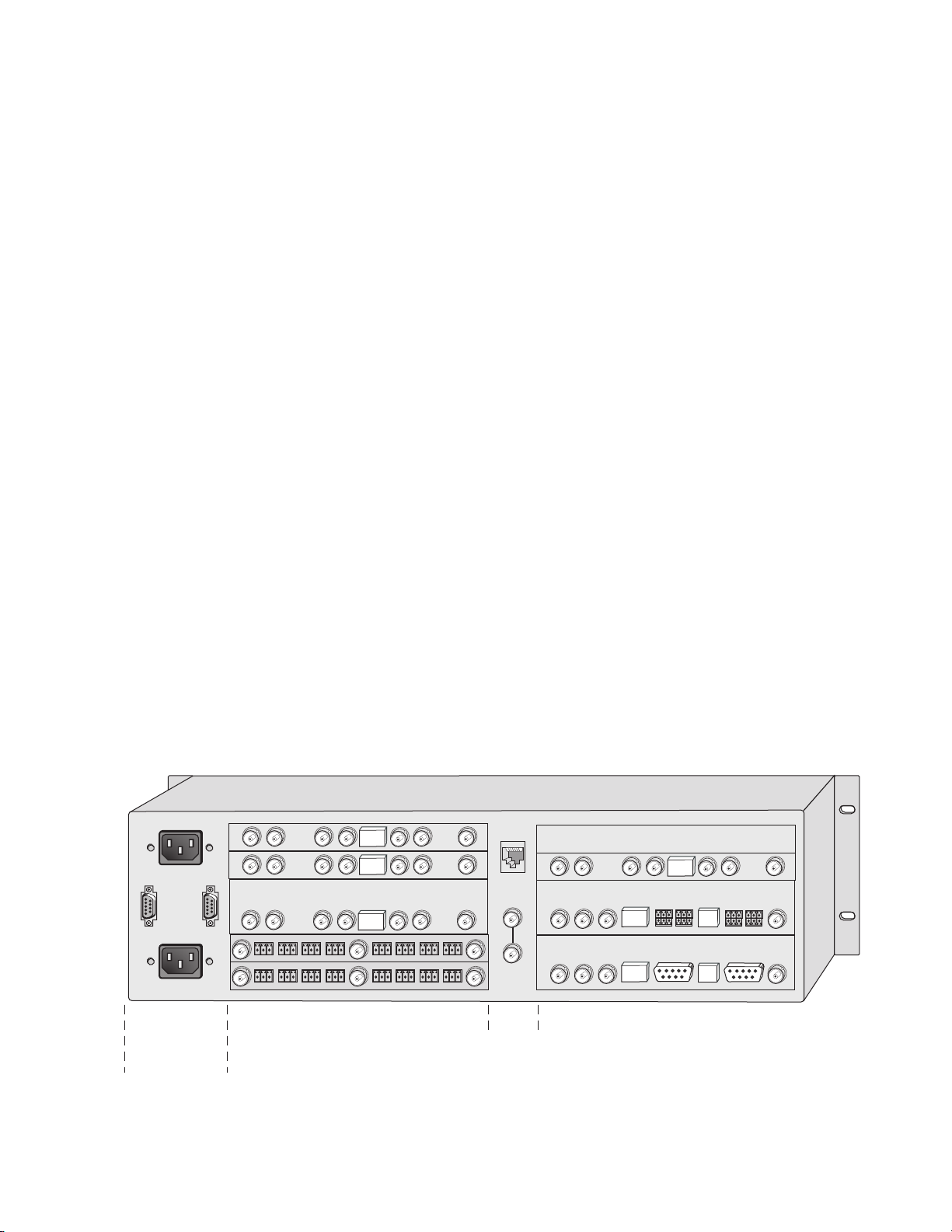
Media section
rear slots 1-6
(with one 2000EMI blank)
Media section
rear slots 7-12
Network
and reference
input connections
Power, frame
configuration,
& frame health
connections
8341_12r2
Installation of the Kameleon HD module is a process of:
• Placing the dual-height KAM-HD-MULTI-UR or KAM-HD-MULTI-BR
rear module in a rear frame slot (no other rear modules can be used),
• Placing the media module in the corresponding front slot, and
• Cabling and terminating signal ports.
The Kameleon HD module can be plugged in and removed from a 2000
Series frame with power on. When power is applied to the module, LED
indicators reflect the initialization process (see Power Up on page 16).
Note The Kameleon HD must be installed in a 2000T1DNG or 2000T3NG frame
(2000NET and 2000GEN module installed) for access to a frame reference.
Module Placement in the 2000 Frame
There are twelve slot locations in both the front and rear of a Kameleon
RU frame to accommodate Kameleon HD modules. The
3
KAM-HD-MULTI module requires a dual height rear module, either the
KAM-HD-MULTI-UR or the KAM-HD-MULTI-BR, that uses two rear
module slots allowing up to 4 modules per 3 RU frame, 2 in a 1 RU frame.
Dual-height modules can be placed in any rear slot as long as there is room
in the frame.
Installation
To install a Kameleon HD module set in a 2000 Series frame:
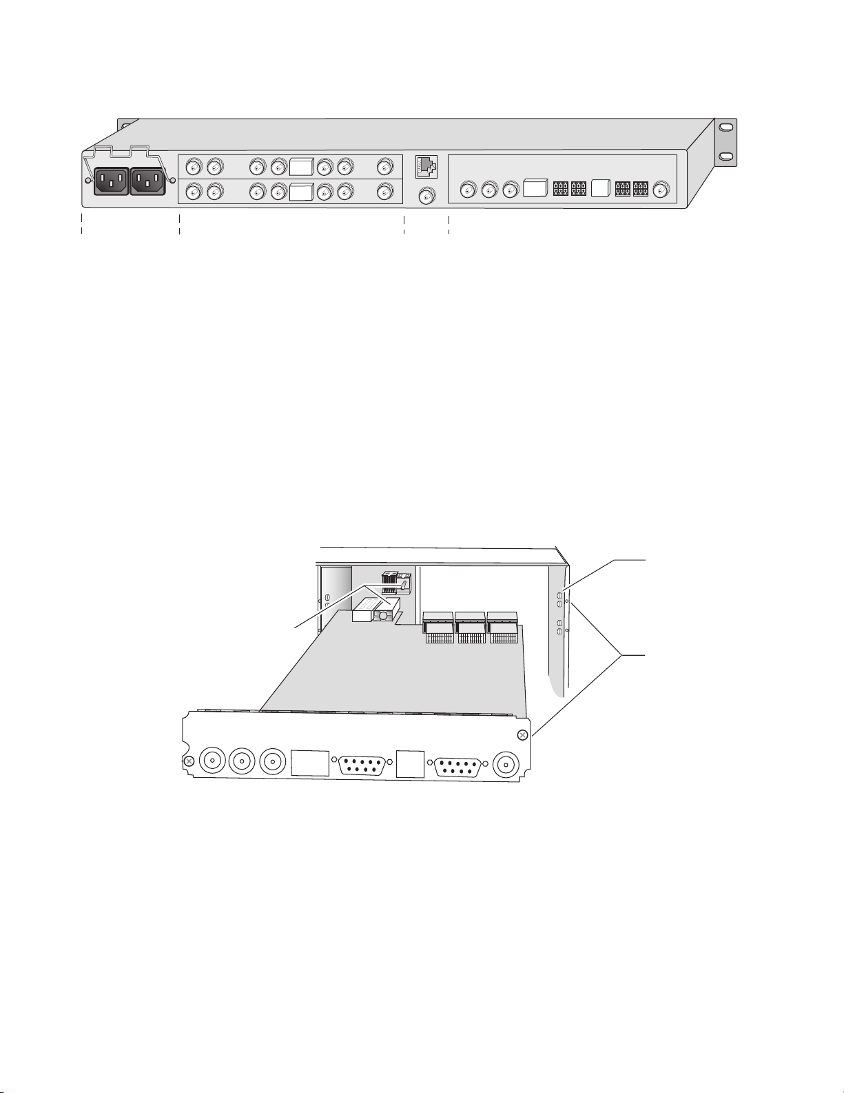
1. Locate a vacant slot in the rear of the 3 RU frame (Figure 1) or the
2000T1DNG frame (Figure 2 on page 12).
Figure 1. 2000T3NG Frame, Rear View
KAM-HD-MULTI—Instruction Manual 11
Page 12
Installation
8341_11r2
Media section
rear slots 1-2
(with VID-HDD-R Rear Module)
J101
1
2
3
4
J102
Media section
rear slots 3-4
Network
and reference
input connections
Power connections
KAM-HD
MULTI-UR
Alignment post
and receptacle
Screw lock
(both sides)
8341_06
2000 frame (rear view)
Board edge guides
(both sides)
Figure 2. 2000T1DNG Frame, Rear View
2. Insert the rear module into the vacant rear slot of the frame as
illustrated in Figure 3.
3. Verify that the module connector seats properly against the midplane.
4. Using a crossblade screwdriver, tighten the two screw locks to secure
the module in the frame.
CAUTION Using the incorrect rear module can cause overheating of the Kameleon 2000
Figure 3. Installing Passive Rear Module
5. Locate the corresponding front media slot (1 -12) in the 3 RU frame
frame.
frame (Figure 4) or front media (slot 1-4) the 1 RU frame (Figure 5).
Place the KAM-HDD/-FS module in the lower slot when using a
dual-height rear module.
12 KAM-HD-MULTI—Instruction Manual
Page 13
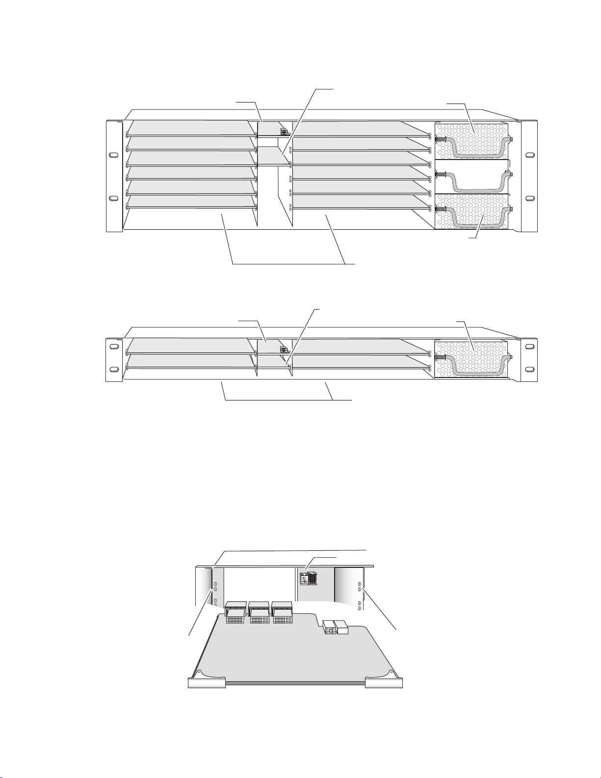
Figure 4. 2000T3NG Kameleon Frame, Front Slots
(2)
(3)
(4)
(5)
(6)
(7)
(8)
(9)
(10)
(11)
(12)
(15)
(13)
(1)
8173-04r1
Network Slot (13)
Reference Distribution Slot (15)
Main Power Supply Slot (18)
Secondary Power
Supply Slot (20)
Front Media Slots (1-12)
Fan Sled
Slot (19)
(2)
(3)
(4)
(5)
(6)
(1)
8039-21
Network Slot (5)
Power Supply Slot (7)
Front Media Slots (1-4)
Reference Distribution Slot (6)
Figure 5. 2000T1DNG Kameleon Frame Front Slot
Installation
6. With the component side up, insert the front media module in the
corresponding front slot (see Figure 6).
7. Verify that the module connector seats properly against the midplane
and rear module connector.
8. Press firmly on both ejector tabs to seat the module.
Figure 6. Installing Front Media Module
2000 Frame (front view)
Alignment post and receptacle
KAM-HD-MULTI—Instruction Manual 13
Board edge
guides
Board edge
guides
8024-06r2
Page 14

Installation
Cabling
All cabling to the Kameleon HD module is done on the corresponding
KAM-HD-MULTI-UR Rear (
inputs) or KAM-HD-MULTI-BR Rear (Figure 8 on page 15 for balanced
audio inputs) at the back of the 2000 frame. There are a number of different
input and output configurations possible depending on system configura
tion and module type.
To determine the correct cabling for your application, refer to System Config
Web Page on page 47 and the I/O Config Web Page on page 43.
Serial or HD SDI Video Input
Connect an SD or HD SDI video input to the BNC connector, labeled VI:
• J8 on the KAM-HD-MULTI-UR Rear
• J10 on the KAM-HD-MULTI-BR Rear
Video Outputs
Figure 7 on page 15 for unbalanced audio
-
There are three SDI video outputs at the following BNC connectors labeled
SDO:
• J1, J6, and J7 on the KAM-HD-MULTI-UR Rear
• J1, J8, and on the J9 KAM-HD-MULTI-BR Rear
Audio Input and Outputs
The balanced and unbalanced audio connectors on the
KAM-HD-MULTI-BR and KAM-HD-MULTI-UR rear modules can be used
as input or outputs. Configuration is done on the I/O Config web page (
Config Web Page on page 43) or using the Audio Preset Config buttons on
the E-MEM web page (E-MEM Web Page on page 85).
The KAM-HD-MULTI-UR comes with two audio breakout cables for connection to the 9-pin D connectors J2 and J4. The outputs from the breakout
cables are labeled A, B, C, and D which correspond to the outputs on the
unbalanced connectors. Refer to Figure 20 on page 44 for 8 In/0 Out,
Figure 21 on page 45 for 4 In/4 Out, and Figure 23 on page 46 for 0
In/8 Out configurations.
Data
I/O
This connection is for future use and currently not used.
Fiber IF
This connection is for future use and currently not used.
14 KAM-HD-MULTI—Instruction Manual
Page 15
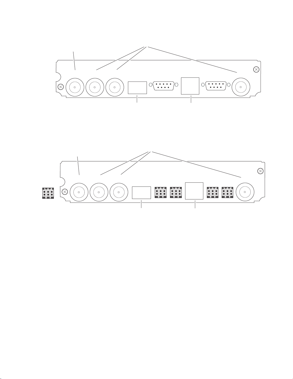
Figure 7. KAM-HD-MULTI-UR Rear Module
FIBER IF
DATA
SDOSDO SDO
J8 J7 J6 J5 J4 J3 J1 J2
VI
KAM-HD
MULTI-UR
8438_03
SD or HD
SDI Input
SD or HD SDI Outputs (3)
Currently
not used
Currently
not used
FIBER IF AES I/OAES I/O AES I/O AES I/O
DATA
SDOSDO SDO
J10 J9 J8 J5J6J7 J4 J3 J1 J2
VI
KAM-HD
MULTI-UR
Dual Audio
Connector
pinout
+ – G
8438_04
SD or HD
SDI Input
SD or HD SDI Outputs (3)
Currently
not used
Currently
not used
AES I/O AES I/O
Figure 8. KAM-HD-MULTI-BR Rear Module
Installation
KAM-HD-MULTI—Instruction Manual 15
Page 16
Power Up
Power Up
Operation Indicator LEDs
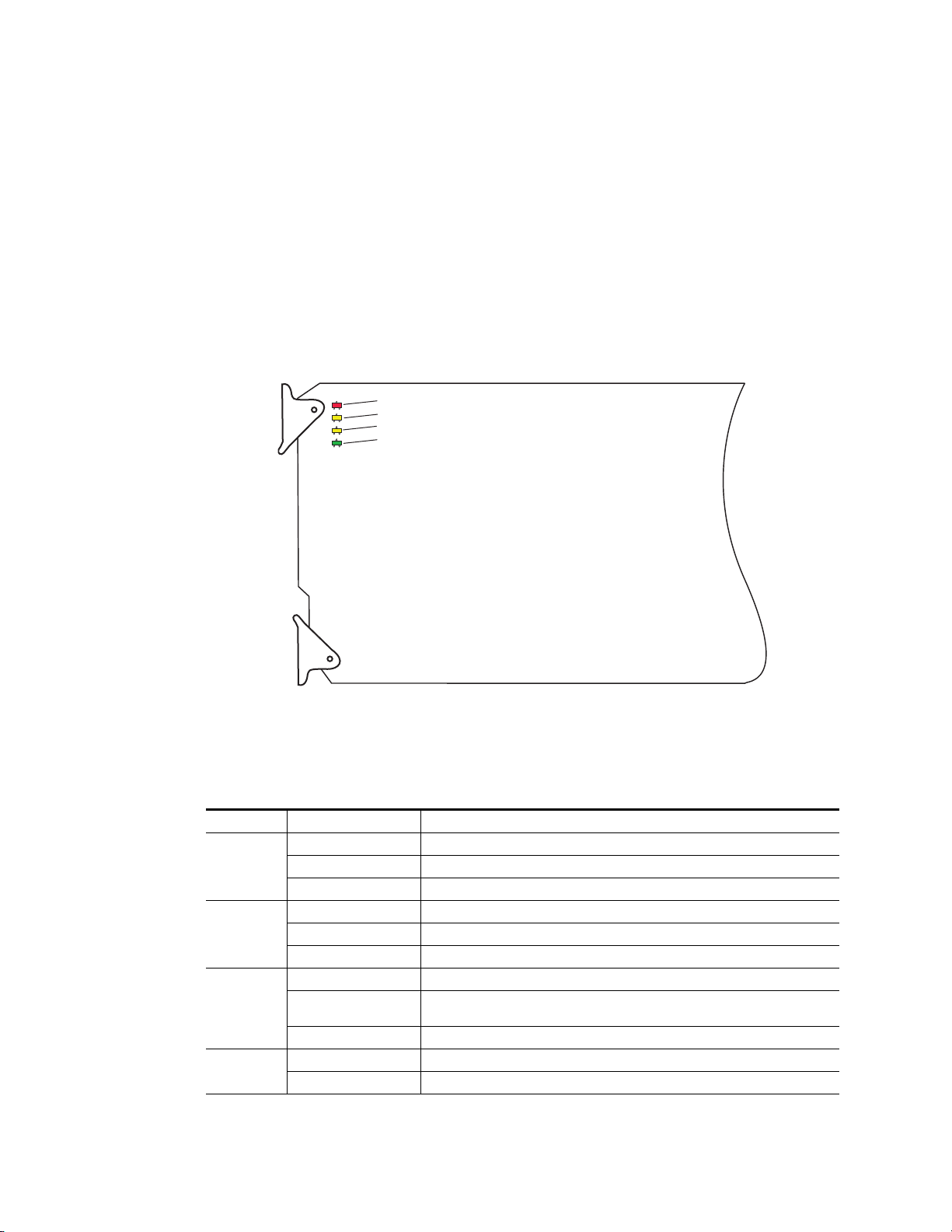
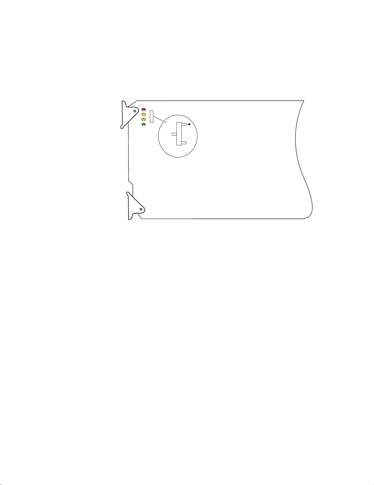
The front LED indicators are illustrated in Figure 9. Upon power-up, the
green PWR LED should light and the yellow CONF LED should illuminate
for the duration of module initialization.
With factory default configuration and valid input and reference signals
connected, only the green PWR LED should be on.
Figure 9. Operation Indicator LEDs
FAULT LED
COMM LED
CONF LED
POWER LED
A red FAULT LED indicates an error situation and, with the other LEDs,
can indicate the operational conditions presented in Tab le 1 .
Table 1. Indicator LEDs and Conditions Indicated
LED Indication Condition
FAULT
(red)
COMM
(yellow)
CONF
(yellow)
PWR
(green)
Off Normal operation.
On continuously Module has detected an internal fault.
Flashing Frame reference or video input is missing, input does not match manual selection.
Off No activity on frame communication bus.
Long flash Location Command received by the module from a remote control system.
Short flash The new system configuration is being stored to the module.
Off Module is in normal operating mode.
On continuously
Long flash Location Command received by the module from a remote control system.
Off No power to module or module’s DC/DC converter failed.
On continuously Normal operation, module is powered.
Module is initializing, changing operating modes or updating firmware. Simultaneous
CONF and FAULT LEDs on indicate FPGA load error.
8341_03
16 KAM-HD-MULTI—Instruction Manual
Page 17
Remote Control Lockout
8245_06
JP2
LOCAL
LCL&REM
1 & 2
2 & 3
When a jumper is placed across pins 1 and 2 of jumper block JP2 (see
Figure 10), module output mode settings are locked out from remote con-
trol. To have remote access, set the jumper across pins 2 and 3.
Figure 10. Local/Remote Jumper
Power Up
KAM-HD-MULTI—Instruction Manual 17
Page 18

Quick Start Procedure
Quick Start Procedure
Follow the procedure below for a quick start method configuration for the
Kameleon HD module:
1. Go to the E-MEM web page (page 85) to select a preset audio
configuration if your audio needs match one of the four preset modes
explained in Audio Preset Configurations on page 23, or set the audio
configuration on the I/O Config web page (I/O Config Web Page on
page 43)
2. Go to the I/O Config web page (page 43) to name inputs and outputs.
3. Go to the System Config web page (page 47) to configure the input
video type (HD or SD), the video input rate, and the output timing
source. Split Screen controls are also available on this page as well as on
the HD Video Proc, SD Video Proc, and Color Correction web pages.
4. If not already connected, connect all input and output signals and
verify component and signal presence and condition on the Status web
page (page 38).
5. Go to the Functional View web page (page 50) to use the block diagram
links to configure each function in turn. Video processing must be
enabled on the System Config web page or with the Newton control
panel before adjustments can be made.
Note Next, Functional View, and Back links are provided to help you navigate
through a logical configuration sequence.
6. Use the Slot Config web page (page 92) to assign Slot Configuration
information such as slot name and asset number. Also link to the
2000NET module web pages to enable and disable Frame Health and
SNMP trap reporting.
7. Use E-MEM memory (page 85) to store or recall configurations as
necessary.
Note Always recall factory defaults after a software update.
8. Refer to Updating Software on page 97 for information on updating
software.
18 KAM-HD-MULTI—Instruction Manual
Page 19

Configuration and Adjustments
Kameleon HD configuration and monitoring can be performed using a web
browser GUI interface or a networked Newton Control Panel. This section
provides an overview of each of these controls along with the configuration
parameters available with each type of control device. It also provides an
overview of the audio configurations available on this module.
Audio Overview
There are a number of audio paths through the KAM-HD-MULTI module
that can be utilized depending on the type of audio application required.
This section gives an overview of the overall audio system and describes
the best uses of each of the audio paths and how to use the audio preset
configurations.
Audio Input Sources
Embedded audio in the SD or HD video input stream is automatically
demultiplexed and copied at the input of the module. Any or all of the eight
demuxed audio streams can be selected to be input streams to the audio
timing circuitry or bypass timing and processing completely, depending on
the type of audio and the application, and be sent directly to the AES out
puts. The embedded audio can also be passed to the video output of the
module unmodified. Audio capabilities for different audio types are sum
marized in Tab le 2 on page 20.
Configuration and Adjustments
-
-
Up to eight external AES audio inputs can be connected to the rear module,
depending on the audio configuration set on the I/O Config web page (I/O
Config Web Page on page 43).
Eight audio sources, can be selected from the list of demuxed inputs
and/or the external AES inputs to make up the audio that can be multiplexed into the output video stream or output to external AES outputs
depending on the I/O configuration of the rear module and other module
configuration setups.
KAM-HD-MULTI—Instruction Manual 19
Page 20

Configuration and Adjustments
KAM-HD-MULTI audio capabilities are summarized in Tab le 2 below:
Tab l e 2 . K A M- HD - MU LT I Audio Capabilities Summary
Audio Source Audio Type
AES Rear Connector Port
Demultiplexed Audio
1
CUVZ Pass Through with asynchronous inputs will cause entire blocks of C, U, and V bits to be periodically skipped or repeated.
2
Only when the input video shares the same genlock reference as the module or when the module is in input-timed mode, are the Demultiplexed streams considered
to be synchronous.
Audio Yes Yes
Non-Audio No Yes
Audio Yes Yes
Non-Audio No Yes
Bypass to AES
Output Ports
Asynchronous Audio
Allowed
Force-flagged as
Asynchronous
CUVZ Passthrough
Permitted
1
1
1, 2
1,2
Mandatory N/A N/A
SRC Bypass
Enabled
Synchronous only Yes or No
Must be enabled Disabled
Synchronous only
Must be enabled Disabled
2
Automatically disabled
when SRC Bypass is
enabled.
The KAM-HD-MULTI module can use a rear module with either balanced
or unbalanced AES audio connectors. Eight audio streams can be con
nected in the following configurations set on the I/O Config web page:
Auto Track
Enabled
-
• 8 inputs/0 outputs – when the module is set for 8 inputs and no outputs, all eight audio connectors on the rear module become inputs for
external AES audio.
• 4 inputs/4 outputs – when the module is set for 4 inputs and 4 outputs,
4 audio connectors become inputs for AES audio and 4 audio connectors become AES audio outputs on the rear module. Refer to the I/O
Config web page for the specific rear module connector numbers.
• 0 inputs/8 outputs – when the module is set for 8 inputs and no outputs, all eight audio connectors on the rear module become inputs for
external AES audio.
AES C/U/V Bits Pass Through
The control bits that are part of each subframe of AES data are defined as
(Channel status), U (User), and V (Valid) bits and the Z bit, which carries
C
the start position of the AES block frame. For the control and status bits in
the CUV positions of each audio channel, and the Z marker for each stream
(pair of channels), there is a buffer on the module that handles the asyn
chronous timebase slips between the input and output AES stream frequency.
This buffer will drop or repeat an entire block (occurring every 192 samples) of CUV bits when the two timebases cross a block boundary rather
than drop or repeat individual bits from the block.
-
20 KAM-HD-MULTI—Instruction Manual
Page 21

A control is provided on the AES Outputs web page for enabling or disabling the control bits in an AES signal called the AES C/U/V Bit Pass
Through (
locally at the AES output of the module (Pass Through disabled) or taken
from the AES stream coming from an audio input or demultiplexed from
video (Pass Through enabled).
As shown in the Audio Capabilities Summary in Table 2 on page 20,
enabling CUVZ pass through to preserve the original data is only permitted when audio is synchronous with the input video. Asynchronous
sources (such as Dolby E and non-audio data) should have this control disabled. If the bits are becoming corrupted, this control can be used to diagnose whether the corruption is occurring before or after the
KAM-HD-MULTI module.
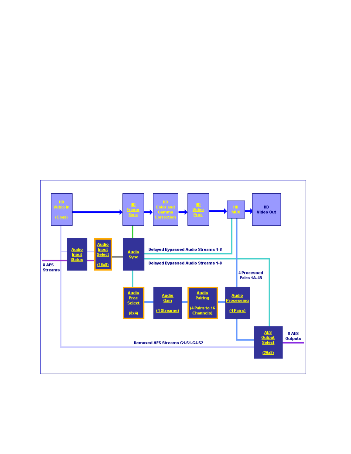
Audio Paths
The main audio paths through the module are explained below and illustrated in the Functional View in Figure 11 on page 22. Refer to Tabl e 2 for
an overview of audio types and how they can be utilized in these paths.
Configuration and Adjustments
AES Outputs Web Page on page 81). These bits may be generated
Input Embedded Audio
The embedded audio present in the video input stream can be passed to the
output of the module unchanged.
Demuxed AES Audio Streams G1.S1-G4.S2
The eight demuxed audio streams, labeled Demuxed AES Streams G1.S1-G4.S4
in the Functional View (
output connectors, bypassing all timing and processing. They are selectable
as AES outputs (depending on module configuration) on the AES Outputs
web page identified as
ground to match the corresponding path on the Functional View diagram.
Figure 11 on page 22), are sent directly to the AES
Demuxed Stream 1-8, colored with a light blue back-
Delayed Bypassed Audio Streams 1-8
Eight audio streams, either demuxed audio streams from the video input
and/or the external AES audio inputs, can be selected as inputs on the
Audio Select web page to pass through the audio synchronizing circuitry
and be adjusted on the Audio Sync web page. These audio streams are
identified as
represented by the cyan colored path.
The Delayed and Bypassed Streams 1-8 can be multiplexed into the video output
stream when the existing embedded audio has been deleted (no audio
replacement is possible) on the Mux web page and/or sent to available AES
outputs depending on module audio configuration.
Delayed and Bypassed Stream 1-8 on the functional diagram and
These outputs are identified as Delayed and Bypassed Streams 1-8 on the Mux
and AES Outputs web pages, colored with a cyan background to match the
corresponding path on the Functional View diagram.
KAM-HD-MULTI—Instruction Manual 21
Page 22
Configuration and Adjustments
Processed Paired 1-4
Four of the eight audio streams selected in the Audio Input Select web
page, either demuxed audio streams and/or the external AES audio inputs,
can be selected as inputs to the audio processor. These four streams can be
paired in any combination on the Audio Channel Pairing web page then
processed as defined on the Audio Proc web page. These audio streams are
identified as
by the blue color path.
Any or all of the four pairs can be multiplexed into the video output stream
when the existing embedded audio has been deleted (no audio replacement is possible) and/or sent to available AES outputs on the rear module.
Processed Pairs 1A-4B on the functional diagram and represented
These outputs are identified as
Outputs web pages, colored with a blue background to match the corresponding path on the Functional View diagram.
Figure 11. Audio Functional View (HD Video Input)
Processed Pairs 1A-4B on the Mux and AES
22 KAM-HD-MULTI—Instruction Manual
Page 23

Audio Preset Configurations
There are four different audio preset configurations. Selection of one of
these configurations is done with the Audio Preset Config buttons on the
E-MEM web page (
tions is intended to preset the audio inputs and outputs and set audio
parameters for a specific audio application.
Note Audio presets are designed to act as a starting point only. You will need to go
through each setup to make sure the parameters meet the needs of your
application.
The following Audio Preset Configs can be selected:
DeEmbed
Selecting DeEmbed configures the module for no AES audio inputs and eight
audio outputs. It is primarily for applications where demultiplexing
embedded audio is required to be output to the external AES audio connec
tors.
E-MEM Web Page on page 85). Each of these configura-
Configuration and Adjustments
-
Embed
Selecting Embed configures the module for eight AES audio inputs and no
AES audio outputs. This application can be used for applications where
external audio is fed to the module and embedded into the output video
stream.
Universal 8 Ch
Selecting Universal 8 Ch configures the module for four AES audio inputs and
four AES outputs. The Demuxed audio Groups 1-2 are sent to the four
external AES outputs. External AES audio inputs 1-4 are multiplexed into
Groups 1 and 2 of the output video stream.
Transcode
Selecting Transcode, configures the module for no AES audio inputs and
eight audio outputs. All eight demuxed audio streams are delayed and
bypassed then selected for insertion into the output audio stream (multi
plexed) and to the eight AES connectors on the rear module.
Refer to Table 3 on page 24 for a complete summary of the settings for each
Audio Preset Configuration.
-
KAM-HD-MULTI—Instruction Manual 23
Page 24

Configuration and Adjustments
Ta bl e 3 gives a summary of the parameter values set on the web pages
when each of the four Audio Preset Configurations are selected.
Table 3. Audio Preset Configuration Summary
Parameters DeEmbed Embed
Num AES
I/O Select
Default
Factory
Names
Sample Rate
Conversion
Report Loss of
Signal
Audio Delay 0 ms Audio Sync
Stream 1: SDI Input G1.S1
Stream 2: SDI Input G1.S2
Audio Input
Selections
(Streams 1-8)
AES Output
Stream
Selections
(AES 1-4 at J4
A-D)
(AES 5-8 at J2
A-D)
Delete all
Input
Demuxed
Groups
Group Insertion (muxing)
Groups 1-4
(Streams
A & B)
AES Output
Resolution
AES C/U/V
Bits Pass
Through
Mode
1
The embedded audio from the input video stream is actually deleted here, not passed through to the output.
Stream 3: SDI Input G2.S1
Stream 4: SDI Input G2.S2
Stream 5: SDI Input G3.S1
Stream 6: SDI Input G3.S2
Stream 7: SDI Input G4.S1
Stream 8: SDI Input G4.S2
1: SDI In G3.S1.SRC.DLY
2: SDI In G3.S2.SRC.DLY
3: SDI In G4.S1.SRC.DLY
4: SDI In G4.S2.SRC.DLY
5: SDI In G1.S1.SRC.DLY
6: SDI In G1.S2.SRC.DLY
7: SDI In G2.S1.SRC.DLY
8: SDI In G2.S2.SRC.DLY
Gp 1 St A:
SDI In G1.S1. SRC.DLY
Gp 1 Str B:
SDI In G1.S2. SRC.DLY
Gp 2 Str A:
SDI In G2.S1. SRC.DLY
Gp 2 Str B:
SDI In G2.S2. SRC.DLY
Gp 3 Str A:
SDI In G3.S1. SRC.DLY
Gp 3 Str B:
SDI In G3.S2. SRC.DLY
Gp 4 Str A:
SDI In G4.S1. SRC.DLY
Gp 4 Str B:
SDI In G4.S2. SRC.DLY
0/8
(0 inputs/8 outputs)
8/0
(8 inputs/0 outputs)
Factory video and audio default names restored
Enabled
Enabled
Stream 1: AES In 1
Stream 2: AES In 2
Stream 3: AES In 3
Stream 4: AES In 4
Stream 5: AES in 5
Stream 6: AES In 6
Stream 7: AES In 7
Stream 8: AES In 8
No AES Outputs
Yes
Gp 1 Str A: AES 1 SRC.DLY
Gp 1 Str B: AES 2 SRC.DLY
Gp 2 Str A: AES 3 SRC.DLY
Gp 2 Str B: AES 4 SRC.DLY
Gp 3 Str A: AES 5 SRC.DLY
Gp 3 Str B: AES 6 SRC.DLY
Gp 4 Str A: AES 7 SRC.DLY
Gp 4 Str B: AES 8 SRC.DLY
24 Bits
Enabled
Universal 8
Channel
4/4
(4 inputs/4 outputs)
Stream 1: SDI Input G1.S1
Stream 2: SDI Input G1.S2
Stream 3: SDI Input G2.S1
Stream 4: SDI Input G2.S2
Stream 5: AES In 1
Stream 6: AES In 2
Stream 7: AES In 3
Stream 8: AES In 4
1: None
2: None
3: None
4: None
5: SDI In G1.S1.SRC.DLY
6: SDI In G1.S2.SRC.DLY
7: SDI In G2.S1.SRC.DLY
8: SDI In G2.S2.SRC.DLY
Gp 1 Str A: AES 1 SRC.DLY
Gp 1 Str B: AES 2 SRC.DLY
Gp 2 Str A: AES 3 SRC.DLY
Gp 2 Str B: AES 4 SRC.DLY
Gp 3 Str A: Pass
Gp 3 Str B: Pass
Gp 4 Str A: Pass
Gp 4 Str B: Pass
1
1
1
1
TransCode
0/8
(0 inputs/8 outputs)
Stream 1: SDI Input G1.S1
Stream 2: SDI Input G1.S2
Stream 3: SDI Input G2.S1
Stream 4: SDI Input G2.S2
Stream 5: SDI Input G3.S1
Stream 6: SDI Input G3.S2
Stream 7: SDI Input G4.S1
Stream 8: SDI Input G4.S2
1: SDI In G3.S1.SRC.DLY
2: SDI In G3.S2.SRC.DLY
3: SDI In G4.S1.SRC.DLY
4: SDI In G4.S2.SRC.DLY
5: SDI In G1.S1.SRC.DLY
6: SDI In G1.S2.SRC.DLY
7: SDI In G2.S1.SRC.DLY
8: SDI In G2.S2.SRC.DLY
Gp 1 Str A:
SDI In G1.S1. SRC.DLY
Gp 1 Str B:
SDI In G1.S2. SRC.DLY
Gp 2 Str A:
SDI In G2.S1. SRC.DLY
Gp 2 Str B:
SDI In G2.S2. SRC.DLY
Gp 3 Str A:
SDI In G3.S1. SRC.DLY
Gp 3 Str B:
SDI In G3.S2. SRC.DLY
Gp 4 Str A:
SDI In G4.S1. SRC.DLY
Gp 4 Str B:
SDI In G4.S2. SRC.DLY
Web
Page
I/O Config
Audio Input
Select
Audio Input
Select
AES
Outputs
HD/SD
MUX
AES
Outputs/
HD or SD
MUX
24 KAM-HD-MULTI—Instruction Manual
Page 25

Configuration Summary
The configuration parameters and monitoring functions available with the
web browser interface and the Newton Control Panel are summarized in
Ta bl e 4. The parameter defaults, choices, ranges, and resolution are pro-
vided for each function.
Table 4. Summary of KAM-HD-MULTI Configuration Controls
Function Default
Input video type HD 59.94
Input rate 1080i 59.94
Select output timing
source
Genlock status – Locked or Unlocked
Enable or disable all
video processing: HD
Video Proc, Color Correction, or SD Video Proc
or set output to Color
Bars test signal
Enable or disable split
screen
Split screen orientation Vertical Horizontal or Vertical
Split screen position
(% of unprocessed video)
Input Frame Reference or Input
Disable
Disabled Enabled or Disabled
50%
Range/Choices
Resolution
HD 59.94,
SD,
HD 50,
or HD 24
HD 59.94:
1080i/59.94 or 720p/59.94
SD:
480i/59.94 or 576i/50
HD 50:
1080i/50 or 720p/50
HD 24:
1080sf/24 or 1080p/24
Enable,
Disable,
or Color Bars
10 to 90%
(1% steps)
Configuration and Adjustments
Web Page/
Function Name
System Config/
Input Type
HD 59.94, SD, HD 50, or HD 24
radio button
System Config/
Input Rate pulldown
System Config/
Output Timing
Source Selection
Frame Reference or Input radio button
System Config/
Output Timing
Genlock read-only status
System Config/
Video Proc Amps Processing:
Disabled, Enabled,
or Color Bars radio button
System Config/, or
Color Correction/, or
HD Video Proc/, or
SD Video Proc/
Split Screen
Split: Enabled checkbox
System Config/, or
Color Correction/, or
HD Video Proc/, or
SD Video Proc/
Split Screen: Orientation:
Vertical or Horizontal radio button
System Config/, or
Color Correction/, or
HD Video Proc/, or
SD Video Proc/
Split Screen: Position (%) control
Newton
Panel
HD/SDMode
VidRMode Set video line rate.
OutClk
Genlock
VidPrcEn
SplitEn
SSOrt
SSPos
Notes/
Conditions
Set video input type.
This will reboot
module to load a
new configuration.
Controls available on
all modules.
Frame Reference
selected as Output
Timing Source
Status of video processing is reported
in each video proc
web page header.
Split screen controls
appear on four different web pages and
all controls are
common, including
control panel.
KAM-HD-MULTI—Instruction Manual 25
Page 26

Configuration and Adjustments
Table 4. Summary of KAM-HD-MULTI Configuration Controls
Function Default
Report input signal
status
Report input video
standard line rate
Adjust horizontal timing
in pixels
Adjust vertical timing
in lines
Minimum Delay Enable Disabled Enabled or Disabled
Loss of signal operation
(Frame Sync
reference timing source
selected)
Manual Freeze mode None
– Present or Not Present
–
0 pixels
0 lines
Auto Freeze
Range/Choices
Resolution
See Input
Rates above
HD 59.94:
1080i/59.94 = 0 to 2199
720p/59.94 = 0 to 1649
SD:
480i/59.94 = 0 to 857
576i/50 = 0 to 863
HD 50:
1080i/50 = 0 to 2639
720p/50 = 0 to 1979
HD 24:
1080sf/24 = 0 to 2749
1080p/24 = 0 to 2749
(1 pixel steps)
HD 59.94:
1080i/59.94 = 0 to 1124
720p/59.94 = 0 to 749
SD:
480i/59.94 = 0 to 524
576i/50 = 0 to 624
HD 50:
1080i/50 = 0 to 1124
720p/50 = 0 to 749
HD 24:
1080sf/24 = 0 to 1124
1080p/24 = 0 to 1124
(1 line steps)
Pass,
Auto Freeze,
or Auto Blue
None, Frame, or Field
(SD input only)
Web Page/
Function Name
HD/SD Video In/
Input Signal State report
HD/SD Video In/
Input Signal Standard report
HD/SD Frame Sync/
Timing Adjustments
H Timing control
HD/SD Frame Sync/
Timing Adjustments
V Timing control
HD/SD Frame Sync/
Minimum Delay Mode
Enabled checkbox
HD/SD Frame Sync/
Loss of Signal Operation
Pass, Auto Freeze, or Auto Blue
radio button
HD/SD Frame Sync/
Manual Freeze Mode Selection
None, Frame or Field radio button
Newton
Panel
SigStt
VidInRt
HTiming
VTiming
N/A
LOS Oper
ManFrzMode
Notes/
Conditions
When input signal is
Not Present, input
video will be
reported as
No Signal.
Timing reference is
set on System
Config web page.
26 KAM-HD-MULTI—Instruction Manual
Page 27

Table 4. Summary of KAM-HD-MULTI Configuration Controls
Function Default
Range/Choices
Resolution
Color Correction and Video Processing Adjustments
Lock R, G, and B gains Unlocked Locked or Unlocked
Adjust R gain 100%
Adjust G gain 100%
Adjust B gain 100%
Adjust R offset 0
Adjust G offset 0
Adjust B offset 0
Lock Gamma correction
controls
Adjust R gamma 1.0 0.25 to 4.00
Adjust G gamma 1.0 0.25 to 4.00
Adjust B gamma 1.0 0.25 to 4.00
Lock HD/SD Y, Cb. and
Cr gains together
Adjust HD/SD Y gain
(contrast)
Adjust HD/SD color
saturation
(chroma gain)
Adjust HD/SD Cb gain 100%
Adjust HD/SD Cr gain 100%
Adjust HD/SD Y Offset
(brightness)
Adjust HD/SD Cb offset 0
Adjust HD/SD Cr offset 0
Adjust HD/SD Hue 0
Delete audio mux groups No Delete Delete or No Delete
Audio group View Select Groups (1-2)
Unlocked Locked or Unlocked
Unlocked Lock or Unlock
100%
100%
0
0 to 200%
(1% steps)
0 to 200%
(1% steps)
0 to 200%
(1% steps)
± 100%
(1% steps)
± 100%
(1% steps)
± 100%
(1% steps)
0 to 200%
(1% steps)
0 to 200%
(1% steps)
0 to 200%
(1% steps)
0 to 200%
(1% steps)
± 100%
(1% steps)
± 100%
(1% steps)
± 100%
(1% steps)
-180 to +179 degrees
(1 degree steps)
Groups (1-2) or
Groups (3-4)
Configuration and Adjustments
Web Page/
Function Name
HD/SD Color Correction/
Video Gain Lock checkbox
HD/SD Color Correction/
R Gain (%)
HD/SD Color Correction/
G Gain (%)
HD/SD Color Correction/
B Gain (%)
HD/SD Color Correction/
R Offset (%)
HD/SD Color Correction/
G Offset (%)
HD/SD Color Correction/
B Offset (%)
HD/SD Color Correction/
Gamma Lock checkbox
HD/SD Color Correction/
R Gamma Correction
HD/SD Color Correction/
G Gamma Correction
HD/SD Color Correction/
B Gamma Correction
HD/SD Video Proc/
Video Proc:
Video Gain Lock checkbox
HD/SD Video Proc/
Video Proc: Y Gain (%)
HD/SD Video Proc/
Video Proc: Color Saturation (%)
HD/SD Video Proc/
Video Proc: Cb Gain (%)
HD/SD Video Proc/
Video Proc: Cr Gain (%)
HD/SD Video Proc/
Video Proc: Y Offset (%)
HD/SD Video Proc/
Video Proc: Cb Offset (%)
HD/SD Video Proc/
Video Proc: Cr Offset (%)
HD/SD Video Proc/
Proc Amp: Hue (Deg)
HD/SD MUX/
Group Status and Delete/
Delete All Input Demuxed Groups check-
box
HD/SD MUX/
View Select/
Groups (1-2) or Groups (3-4)
Radio buttons
Newton
Panel
RGBGnLok
RGn
GGn
BGn
ROff
GOff
BOff
RGBGmLok
RGmC
GGmC
BGmC
YSatGnLok or
SdVidGnLk
HdYGn or
SdYGn
HdChroGn or
SdChroGn
HdCbGn or
SdCbGn
HdCrGn or
SdCrGn
HdYOff or
SdYOff
HdCbOff or
SdCbOff
HdCrOff or
SdCrOff
HdChroPhs or
SdChroPhs
N/A
N/A
Notes/
Conditions
Web page will display either SD or HD
Color Correction title
depending on input
video
type selected.
Video Proc Amps
must be enabled on
System Config web
page.
Video Proc Amps
must be enabled on
System Config
web page.
Video Proc Amps
must be enabled on
System Config
web page.
Existing embedded
audio must be
deleted for multiplexing new audio.
KAM-HD-MULTI—Instruction Manual 27
Page 28

Configuration and Adjustments
Table 4. Summary of KAM-HD-MULTI Configuration Controls
Function Default
Audio group insertion
choices for embedding in
output video.
Set AES Output
Resolution for each
output group
Set AES C/U/V Bits Pass
Through
SD video EDH Insertion Enabled Enabled or Disabled
Audio input status
reporting reset
Select audio input
streams.
(Inputs available depend
on module I/O configuration)
Enable sample rate conversion (SRC) for each
audio stream
Report Loss of Signal to
upper levels
Enable auto tracking for
all audio streams 1-8
Enable audio disruption
processor
Select audio stream for
adjustment or viewing
Pass
24 bit 20 or 24 bit
Enabled Enabled or Disabled
––
Force Silence
Enabled Enabled or Disabled
Enabled Enabled or Disabled
On On or Off
Off On or Off
Streams (1-2)
Range/Choices
Resolution
Pass Input Embedded Audio
Processed Pair 1-4
Delayed and Bypassed
Stream 1-8
Force Silence
SDI Input G1.S1 and S2
SDI Input G2.S1 and S2
SDI Input G3.S1 and S2
SDI Input G4.S1 and S2
SDI Input G5.S1 and S2
SDI Input G6.S1 and S2
SDI Input G7.S1 and S2
SDI Input G8.S1 and S2
AES 1-8
Streams (1-2)
Streams (3-4),
Streams (5-6), or
Streams (7-8)
Web Page/
Function Name
HD/SD MUX/
Group Insertion/
Group 1-2 and Group 3-4
Streams A and B
HD/SD MUX/
AES Output Resolution/
20 or 24 bit radio button
HD/SD MUX/
AES C/U/V Pass Through/
Enabled Checkbox
SD Video Out/
Output Video
EDH Insertion Enabled Checkbox
Audio Input Status/
Reset button for individual audio streams
or Reset All button for all audio stream
reporting
Audio Input Select/
Inputs Streams 1-4 or 5-8
radio button
Audio Input Select/
Inputs Streams 1-4 or 5-8
Sample Rate Convert
Disable checkbox
Audio Input Select/
Inputs Streams 1-4 or 5-8
Loss of Signal Report checkbox
Audio Sync/
Enable Auto Tracking On checkbox
Audio Sync/
Enable Audio Disruption Processing On
checkbox
Audio Sync/
View Select radio buttons
Newton
Panel
G1SASdMux
G1SBSdMux
G2SASdMux
G2SBSdMux
G3SASdMux
G3SBSdMux
G4SASdMux
G4SBSdMux
or
G1SAHdMux
G1SBHdMux
G2SAHdMux
G2SBHdMux
G3SAHdMux
G3SBHdMux
G4SAHdMux
G4SBHdMux
N/A
N/A
EDHInsert SD input only
N/A
N/A
N/A
N/A
AuTkEnbl
N/A
N/A
Notes/
Conditions
Delete All Input
Demuxed Groups
checkbox must be
checked to multiplex
audio streams into
output.
Refer to AES C/U/V
Bits Pass Through
on page 20
Disabling SRC for an
audio stream will
automatically disable
auto tracking for that
stream. See also
Table 2 on page 20
Not available in
1080sf/24 or
1080p/24 formats.
28 KAM-HD-MULTI—Instruction Manual
Page 29

Function Default
Auto tracking status
for each audio stream.
Amount of Auto
Tracking Delay
Amount of total audio
delay for each channel
Lock delay adjustments
for each audio stream
(Ch 1 and Ch 2)
Delay adjustments for
each audio stream
(Ch 1 and Ch 2)
Audio processing select Force Silence
Audio Gain view
selection
Lock gain adjustments for
each audio stream
(Ch 1 and Ch 2)
– Enabled or Disabled
––
––
Unlocked Lock or Unlocked
0 ms 0 to 5180 ms
Streams (1-2)
Unlocked Lock or Unlocked
Configuration and Adjustments
Table 4. Summary of KAM-HD-MULTI Configuration Controls
Range/Choices
Resolution
Stream (1-2), (3-4), (5-6), and (7-8)
Stream (1-2), (3-4), (5-6), and (7-8)
Stream (1-2), (3-4), (5-6), and (7-8)
Stream (1-2), (3-4), (5-6), and (7-8) Ch
8 Audio Input Streams
from Audio Input Select
web page
Streams (1-2) or
Streams (3-4)
Web Page/
Function Name
Audio Sync/
Auto Tracking Status
Audio Sync/
Auto Tracking Delay
Audio Sync/
Tot al Delay
Audio Sync/
Channel Delay Lock checkbox
Audio Sync/
1 and Ch 2 Delay Adjust (ms)
Audio Processing Select/
Stream 1 – Stream 4
radio buttons
Audio Gain/
View Select radio button
Audio Gain/
Streams (1-2) or (3-4)
Channel Gain Lock checkbox
Newton
Panel
AuTkStt1
AuTkStt2
AuTkStt3
AuTkStt4
AuTkStt5
AuTkStt6
AuTkStt7
AuTkStt8
AT_Delay
S1Ch1TDly
S1Ch2TDly
S2Ch1TDly
S2Ch2TDly
S3Ch1TDly
S3Ch2TDly
S4Ch1TDly
S4Ch2TDly
S5Ch1TDly
S5Ch2TDly
S6Ch1TDly
S6Ch2TDly
S7Ch1TDly
S7Ch2TDly
S8Ch1TDly
S8Ch2TDly
AdjDTyp1
AdjDTyp2
AdjDTyp3
AdjDTyp4
AdjDTyp5
AdjDTyp6
AdjDTyp7
AdjDTyp8
S1Ch1Dly
S1Ch2Dly
S2Ch1Dly
S2Ch2Dly
S3Ch1Dly
S3Ch2Dly
S4Ch1Dly
S4Ch2Dly
S5Ch1Dly
S5Ch2Dly
S6Ch1Dly
S6Ch2Dly
S7Ch1Dly
S7Ch2Dly
S8Ch1Dly
S8Ch2Dly
N/A
N/A
N/A
Notes/
Conditions
Read-only reporting
of total auto tracking
delay in ms.
Read-only reporting
of total amount of
audio delay for each
audio channel in ms.
Select 4 streams of
audio for processing
from the 8 streams of
audio selected on the
Audio Input Select
web page.
KAM-HD-MULTI—Instruction Manual 29
Page 30

Configuration and Adjustments
Table 4. Summary of KAM-HD-MULTI Configuration Controls
Function Default
Gain adjustments for
each audio stream
(Ch 1 and Ch 2)
Audio Channel Pairing
view selection
Audio channel pairing
Audio Proc view
selection
Audio processing
output selection
AES Outputs view
selection
AES Output Pairs
selection
Set AES Output
Resolution for each
output stream
Set AES C/U/V Bits Pass
Through
0 dB
Pairs (1-2)
Force
Silence
Pairs (1-2)
In1
First Set of
AES Outputs
–
24 bit 20 or 24 bit
Enabled Enabled or Disabled
Range/Choices
Resolution
-40 to + 6 dB
(0.1 dB steps)
Pairs (1-2),
Pairs (3-4),
or Backup
Proc Amp Inputs
(audio stream choices made
on the Audio Processing
Select web page)
Pairs (1-2) and
Pairs (3-4)
In1
-In1
In2
-In2
In1+In2
-(In1+In2)
In1-In2
-(In1-In2)
1 Khz
400 Hz
Silence
ID
First Set of AES Outputs and
Second Set of AES Outputs
I/O Config 8/0:
There are no AES Outputs for
First or Second Set.
I/O Config 4/4:
First Set of AES Outputs
Silence
Processed Pair 1-4,
Delayed and Bypassed
Stream 1-8, and
Demuxed Streams 1-8
Second Set of AES Outputs:
There are only 4 AES
Outputs.
I/O Config 0/8:
First Set of AES Outputs
Silence
Processed Pair 1-4,
Delayed and Bypassed
Stream 1-8, and
Demuxed Streams 1-8
Second Set of AES Outputs:
Same as First Set
Web Page/
Function Name
Audio Gain/
Streams (1-2) or (3-4)
Ch 1 and Ch 2 Gain Adjust (dB)
Audio Channel Pairing/
View Select radio button
Audio Channel Pairing/
Pair 1-4 Ch A and B/
Proc In 1 and 2 radio buttons
Audio Proc/
View Select radio button
Audio Proc/
Pair 1 – Pair 4
ChA and ChB
AES Outputs/
First Set of AES Outputs and
Second Set of AES Outputs
radio buttons
AES Outputs/
AES Output Pairs
KAM-HD-MULTI-UR Rear
First Set of AES Outputs:
Output-J2A (AES 5)
Output-J2B (AES 6)
Output-J2C (AES 7)
Output-J2D (AES 8)
Second Set of AES Outputs:
Output-J4A (AES 1)
Output-J4B (AES 2)
Output-J4C (AES 3)
Output-J4D (AES 4)
KAM-HD-MULTI-BR Rear
First Set of AES Outputs:
Output-J2A (AES 5)
Output-J2B (AES 6)
Output-J3A (AES 7)
Output-J3B (AES 8)
Second Set of AES Outputs:
Output-J5A (AES 1)
Output-J5B (AES 2
Output-J6A (AES 3)
Output-J6B (AES 4
AES Outputs/
AES Output Resolution/
20 or 24 bit radio button
AES Outputs/
AES C/U/V Pass Through/
Enabled Checkbox
Newton
Panel
S1Ch1Gn
S1Ch2Gn
S2Ch1Gn
S2Ch2Gn
S3Ch1Gn
S3Ch2Gn
S4Ch1Gn
S4Ch2Gn
N/A
N/A
N/A
Pr1AProc
Pr1BProc
Pr2AProc
Pr2BProc
Pr3AProc
Pr3BProc
Pr4AProc
Pr4BProc
N/A
J2A or J3A
J2B or J3B
J2C or J2A
J2D or J2B
J4A or J6A
J4B or J6B
J4C or J5A
J4D or J5B
N/A
N/A
Notes/
Conditions
Create 16 Proc Amp
Inputs.
Select type of output
processing for Ch A
and Ch B of each
Audio Pair.
AES Output connector JXX numbers will
depend on type of
rear module. Output
choices will depend
on audio I/O configuration.
Refer to AES C/U/V
Bits Pass Through
on page 20. See also
Table 2 on page 20.
30 KAM-HD-MULTI—Instruction Manual
Page 31

Newton Control Panel Configuration
A Newton Control Panel (hard or soft version) can be interfaced to the
Kameleon 2000 Series frame over the local network. Control panel access
offers the following considerations for module configuration and moni
toring:
• Ability to separate system level tasks from operation ones, minimizing
the potential for on-air mistakes.
• Ability to group modular products—regardless of their physical locations—into logical groups (channels) that you can easily manipulate
with user-configured knobs.
• Update software for applicable modules and assign frame and panel IP
addresses with the NetConfig Networking application.
• Recommended for real-time control of module configuration parameters, providing the fastest response time.
Note Not all module functions are available with the control panel, such as E-MEM
and factory default recalls. The available control panel controls for the
module are listed in Table 4 on page 25.
Configuration and Adjustments
-
An example of the Newton Configurator is shown in Figure 12.
Figure 12. Newton Configurator Example
Refer to the documentation that accompanies the Newton Modular Control
System for installation, configuration, and operation information.
KAM-HD-MULTI—Instruction Manual 31
Page 32

Configuration and Adjustments
Web Browser Interface
The web browser interface provides a graphical representation of module
configuration and monitoring.
Use of the web interface offers the following considerations:
• Provides complete access to all module status and configuration func-
• Web access will require some normal network time delays for pro-
tions, including naming of inputs and outputs, factory parameter and
name default recalls, E-MEM functions, slot configuration, and SNMP
monitoring controls.
cessing of information.
• Configuration parameter changes may require pressing the
Enter, upload processing time, and a manual screen refresh to become
or
effective.
• Web interface recommended for setting up module signal and slot
names, E-MEMS, and reporting status for SNMP and monitoring.
Refer to the Frame Status page shown in Figure 13 on page 33. The Kameleon and 2000 modules can be addressed by clicking either on a specific
module icon in the frame status display or on a module name or slot
number in the link list on the left.
Note The physical appearance of the menu displays on the web pages shown in
this manual represent the use of a particular platform, browser and version
of 2000NET module software. They are provided for reference only. Displays
will differ depending on the type of platform and browser you are using and
the version of the 2000NET software installed in your system. This manual
reflects 2000NET software version 4.0.2.
Apply button
32 KAM-HD-MULTI—Instruction Manual
Page 33

8341_09r2
The Links section lists the frame and its current modules. The selected link's Status
page is first displayed and the sub-list of links for the selection is opened. The sub-list
allows you to select a particular information page for the selected device.
Content display section
displays the information page
for the selected frame or module (frame slot icons are also
active links).
Refresh button for manual
update of page
Figure 13. 2000NET GUI
Configuration and Adjustments
KAM-HD-MULTI—Instruction Manual 33
Page 34

Configuration and Adjustments
Web Page Operations and Functional Elements
The following conventions and functional elements (shown at left) are used
in Kameleon web page operations. (The examples shown throughout this
manual represent 2000NET software version 4.0.0 or later):
Pulldown Menus
Button
Radio button
Check box
Refresh button
Coarse Adjust
Fine Adjust
Enter
Low Limit
Status Indicator
Entry Field
High Limit
• Pulldown menus allow you to choose selections from a list.
• Clicking on a button performs an immediate action such as recall of
defaults, clearing of states, learning configurations, and selecting all or
none of a selection.
• Radio buttons are used to make a choice of one parameter in a group.
• Check boxes are used when a selection can be enabled or included in a
group. Multiple check box selections or enables can be made for some
parameters.
Refresh button (circular arrow) is provided at the top of each web page
•A
for manual refresh to view recently changed parameters.
• Each numerical adjustment control has a
Coarse adjust button (left and
right top double arrows) which increases or decreases the step value by
a factor of 10. The
Fine adjust button (left and right inside single arrows)
increases or decreases the step value by 1.
To change a value, use the arrow button controls or enter a value into
the number field and select the
Enter button (*) or use the Enter key on
your keyboard. The Status Indicator bar will follow the value selected.
Use the Low and High Limit buttons to go directly to the lowest and
highest limits for the parameter.
Status LED
• An entry field allows naming of various module functions such as
8341_13
input or output signals, asset tag, and slot identification.
• The Status LED is explained in Status LED Icon on page 35.
34 KAM-HD-MULTI—Instruction Manual
Page 35

Status and Identification Header
Each configuration web page has a Status and Identification Header
reporting various status and configuration items on the module
Figure 14).
(
Figure 14. Status/ID Header
Status LED Icon
The Status LED icon reports communication status for the frame slot and is
a link to the module Status web page where Warnings and Faults are dis
played.
Configuration and Adjustments
-
LED colors indicate:
• Green = Pass – no problems detected
• Yellow = Configuration error warning
• Red = Fault condition detected
Identification Header
The following module status items are reported in the header:
• Model and Description are read-only generated by the module.
Frame Location is defined on the 2000 Series Kameleon Frame Configura-
•
tion web page.
Slot number reports the module’s location in the frame.
•
Input Video Standard reports the input video type and rate selected on the
•
System Config web page.
Input Video reports the status of the video input to the module.
•
Output Timing Source reports the output timing source (Frame Reference
•
or Input) chosen on the System Config web page.
Split Screen status is reported (Enabled or Disabled) as set on the System
•
Config, Color Correction, or HD and SD Video Proc Amp web pages.
Last Recalled E-MEM reports the last E-MEM configuration recalled.
•
Down Converter Output Line Rate – not applicable in this application.
•
KAM-HD-MULTI—Instruction Manual 35
Page 36

Kameleon HD Links and Web Pages
Kameleon HD Links and Web Pages
The 2000 GUI provides the following links and web pages for the
KAM-HD-MULTI modules:
• Status – reports input, reference, and frame bus status and module
information (page 38),
• I/O Config – shows a graphic representation of inputs and outputs to
the module and allows naming of the input and output signals
(page 43),
• System Config – provides output timing selection, input video type
select, video rate select, video processor enable, color bars test signal
enable, and split screen controls (page 47),
• Functional View – shows a block diagram of the module with links to
each module configuration page (page 50),
• Module Configuration pages for setting up the module (page 52),
• E-MEM® – provides Standard and Advanced E-MEM for Learn and
Recall functions for up to 5 E-MEM registers, and Recall of Factory settings and names, and four Preset Audio Config buttons for automatic
audio configuration (page 85), and
• Slot Config – provides a Locate Module function, Slot Identification
fields, Slot Memory, and links to the Frame Health, LED, and SNMP
reporting lon the 2000NET module (page 92).
36 KAM-HD-MULTI—Instruction Manual
Page 37

Kameleon HD Links and Web Pages
The KAM-HD-MULTI module links are shown in Figure 15 for available web pages when an HD input type is selected (left) or an SD input (right).
Figure 15. KAM-HD-MULTI Web Page Links
KAM-HD-MULTI—Instruction Manual 37
Page 38

Kameleon HD Links and Web Pages
Use
this
link
Status Web Page
The Status web page provides an overall indication of the health of the
system, audio configuration information, r
provides links to web pages for the active components:
ear module type installed, and
• Status Header – see Status and Identification
• Color-coded communication status for each component and path,
• Summary of all fault/warning conditions, and
• Textual module status, front module, and rear module properties.
Status web page views differ according to the different audio configurations. The different audio configurations are shown in the following illustrations:
8 In/0 Out – the Status web page for a module with an audio configura-
•
tion of 8 inputs and no outputs is illustrated in Figure 16 on page 40.
Refer to this illustration for an example of a full Status web page.
•
4 In/4 Out – the reporting section of a Status web page for a module with
an audio configuration of 4 inputs and 4 outputs is illustrated in
Figure 17 on page 41.
0 In/ 8 Out – the reporting section of a Status web page for a module with
•
an audio configuration of no inputs and 8 outputs is illustrated in
Figure 18 on page 41 (Unbalanced Rear) and Figure 19 on page 42 (Bal-
anced Rear).
Header on page 35,
Status Boxes
Each box represents a Kameleon front or rear module. The
KAM-HD-MULTI-UR or -BR link in the Rear I/O Module box will take you
to the I/O Config web page for setting input and output names. The
module link in the Front Processing module box will take you to the Functional view web page containing the configuration links.
The arrows represent audio and video signal paths that may or may not be
monitor
links when their function is active (indicated by underlined function
name).
Color code:
• Green = Pass – operating as expected.
• Yellow = Warning – signal is absent, has errors, or is misconfigured.
• Red = Fault – a component has failed.
• Gray = Not monitored.
ed. Audio paths represent AES audio inputs. These elements act as
38 KAM-HD-MULTI—Instruction Manual
Page 39

Warning/Fault Summary
Warnings and faults are reported in the Warning/Fault summary section of
the Status web page. When a fault or warning is detected, it will be reported
in this area.
A Fault indicates a serious condition that prohibits proper operation.
A Warning indicates a condition which may or may not adversely affect
operating conditions, but should be noted. Warnings may possibly be corrected by changing configuration, settings or input signals.
Status/Front Module Properties
The Status/Front Module properties in the footer provide a textual
summary of the color-coded module status. Front module properties
provide hardware, firmware, software identification, and serial number
and asset tag assignment for the Kameleon HD module.
Kameleon HD Links and Web Pages
KAM-HD-MULTI—Instruction Manual 39
Page 40

Kameleon HD Links and Web Pages
Warning and Fault
summary section
Figure 16. Kameleon HD Status Web Page – 8In/0 Out
40 KAM-HD-MULTI—Instruction Manual
Page 41

Figure 17. Kameleon HD Status Web Page – 4 In/4 Out
Kameleon HD Links and Web Pages
Figure 18. Kameleon HD Status Web Page – 0 In/8 Out
KAM-HD-MULTI—Instruction Manual 41
Page 42

Kameleon HD Links and Web Pages
Figure 19. Kameleon HD Status Web Page – Balanced Rear (8 In/0 Out
42 KAM-HD-MULTI—Instruction Manual
Page 43

I/O Config Web Page
Use
this
link
Use the I/O Config web page to:
• View a graphical overview of the rear module connectors,
See signal status of inputs,
•
• Set audio input and output configuration, and
• Assign easily recognizable signal names that will help later in the con-
figuration process.
Num AES I/O Select
Use the radio buttons to select the audio input/output configuration for the
balanced or unbalanced audio.
The choices for audio inputs and outputs are the following:
•
8 In/0 Out – the balanced or unbalanced AES connectors all become audio
inputs (Figure 20 on page 44 for unbalanced rear). This setting is automatically selected when the Audio Preset Configs
selected on the E-MEM web page.
Kameleon HD Links and Web Pages
Embed button is
4 In/4 Out – balanced or unbalanced AES connectors all become audio
•
inputs (Figure 21 on page 45 for unbalanced rear and Figure 22 on
page 45 for balanced rear). This setting is automatically selected when
the Audio Preset Configs
web page.
0 In/ 8 Out – the balanced or unbalanced AES connectors all become
•
audio outputs (Figure 23 on page 46). This setting is automatically
selected when the Audio Preset Configs
the E-MEM web page.
Header Row
The top header row provides the connector hardware physical label (J#)
and the dedicated signal type for the connector. This information is determined by the rear module type.
Connector
The connector row illustrates connector types provided for each port.
Input/Output Mode
Universal 8 Ch button is selected on the E-MEM
DeEmbed button is selected on
The I/O mode is static read-only based on the type of module and the settings made on the I/O Config web page.
KAM-HD-MULTI—Instruction Manual 43
Page 44

Kameleon HD Links and Web Pages
Signal Naming
Enter a signal name (up to 12 characters) for each operational
input/output. The name will be used to identify the signal in other config
uration web pages. Factory default names for all models are shown on the
individual I/O web pages for each model. Use the Recall Factory Names
Defaults button to return the signal names to factory defaults. This control is
also available on the E-MEM web page.
Status Boxes
As shown in the Legend at the bottom of the I/O Config web page, each
connector is monitored and status reported with the following color code:
• Green = Pass – signal is present.
• Yellow = Warning – signal is absent, has errors, or is misconfigured.
• Light gray = connector is not monitored.
• Dark gray = connector is unused.
-
Figure 20. KAM-HD-MULTI-UR I/O Config Web Page – 8 In/0 Out
44 KAM-HD-MULTI—Instruction Manual
Page 45

Kameleon HD Links and Web Pages
Figure 21. KAM-HD-MULTI-UR I/O Config Web Page – 4 In/4 Out
Figure 22. KAM-HD-MULTI-BR I/O Config Web Page – 4 In/4 Out
KAM-HD-MULTI—Instruction Manual 45
Page 46

Kameleon HD Links and Web Pages
Figure 23. KAM-HD-MULTI-UR I/O Config Web Page – 0 In/8 Out
46 KAM-HD-MULTI—Instruction Manual
Page 47

System Config Web Page
Use
this
link
Refresh button
The System Config web page (Figure 25 on page 48) provides the following
system configuration controls:
Kameleon HD Links and Web Pages
• Selection of the SD or HD input video type and
• Enabling or disabling all HD and SD video processing, including color
• Selection of an output timing source.
• Enabling or disabling of the split screen function and screen position for
Input Video
Select the desired video input type and rate from the Input Type radio buttons
and
available input types and rates.
Note Pressing the Defaults button or changing the Input Type from HD to SD on
Figure 24. Wait Page
rate for the module.
correction or enable a color bars output test signal.
comparing the input video to the processed video. This function is also
on the HD and SD Video Proc and Color Correction web pages.
Input Rate pulldowns. Refer to Ta bl e 4 on page 25 for a complete list of
the System Config web page or with an E-MEM recall will cause the module
to reboot. It will take approximately 30 seconds to re-initialize. During this
time a Wait Page (Figure 24) will appear. Wait for the operation to complete
then select the Refresh button to update the web page.
KAM-HD-MULTI—Instruction Manual 47
Page 48

Kameleon HD Links and Web Pages
Video Proc Amps
Enable or disable all HD and SD video processing, including color correction on the module with the Enabled or Disabled radio button. Proc amp
status will be reported on each of the Video Proc and Color Correction web
pages. Select the
signal on the module output.
Note The internal Color Bars test signal is inserted at the output after the video pro-
Figure 25. KAM-HD-MULTI System Config
Color Bars radio button to enable the internal color bars test
cessing and is not adjustable with the video processor.
48 KAM-HD-MULTI—Instruction Manual
Page 49

Output Timing
For all modules, an output timing source can be selected from the following:
• Frame Reference – when Frame Reference is selected, modules with frame
sync capability (KAM-HD-FS and KAM-HDD-FS) can be genlocked to
the frame reference inserted into the 2000 frame. For these modules, a
Frame Sync web page provides horizontal and vertical timing and
freeze modes.
For modules without frame sync, when the Output Timing source is
selected as
sync to the start of any horizontal line in the frame reference.
• Input – selecting this control will set the timing of the module relative to
the input video signal of the module.
Split Screen
Use a horizontal or vertical split screen to compare the unprocessed input
video (top or right) to the processed output video (bottom or left).
Kameleon HD Links and Web Pages
Frame Reference, the start of any line of the output signal will
• Split Enabled – enable the split screen by checking the Split Enabled
checkbox.
Orientation – set the orientation of the split screen with the Vertical or Hor-
•
izontal
radio button.
Position – use the Position control to set the amount of horizontal or ver-
•
tical split (10 to 90%) of unprocessed video to appear on the screen.
This control is the same as the other Split Screen controls on the Color Correction, HD Video Proc, and SD Video Proc web pages.
KAM-HD-MULTI—Instruction Manual 49
Page 50

Kameleon HD Links and Web Pages
Use
this
link
Functional View Web Pages
The Functional View web pages illustrate a block diagram of the Kameleon
HD front media module showing module fu
are active or inactive in the current configuration. They can be used as a link
map for configuring module functions. Each block has a link to the configuration page for that function. Use the
Kameleon HD module in the order of the signal flow.
nctions and signal paths that
Functional View to configure the
Color coding indicates active functions
nents are inactive due to hardware and/or software constraints. Underlined module functions are links to the web page for that function.
The Functional View for the KAM-HD-MUL
type selected is shown in Figure 26.
Figure 26. KAM-HD-FS Functional View Web Page – HD Input Type
and signal flow. Grayed compo-
TI module with an HD input
50 KAM-HD-MULTI—Instruction Manual
Page 51

Use
this
link
Kameleon HD Links and Web Pages
Figure 27 shows a Functional View for a KAM-HD-MULTI module with an SD input type selected.
Figure 27. KAM-HD-MULTI Functional View Web Page – SD Input Type
KAM-HD-MULTI—Instruction Manual 51
Page 52

Kameleon HD Links and Web Pages
Module Configuration Web Pages
Module configuration and monitoring is provided for the following HD or
SD video and audio functions (depending on video input type and audio
configuration setting) with the web browser GUI or control panel interface:
• HD or SD Video In (page 53)
• HD or SD Frame Sync (page 54)
• HD or SD Color Correction (page 58)
• HD or SD Video Proc (page 60)
•HD or SD MUX (page 62)
•SD Video Out (page 65)
•Audio Input Status (page 66)
• Audio Input Select (page 69)
•Audio Sync (page 72)
• Audio Processing Select (page 74)
• Audio Gain (page 75)
• Audio Channel Pairing (page 77)
•Audio Proc (page 79)
•AES Outputs (page 81)
Note Presence of some of the web pages listed above depends on module type and
system configuration. HD or SD video input type is set on the System Config
web page.
A summarized list of all control parameters and default values is given in
a Configuration Summary table on page 25.
Use the
return the values on that page to the defaults listed in the Configuration
Summary table.
Note Pressing the Defaults button on the System Config web page will reboot the
Select the Previous, Functional View, or Next links on the bottom of each config-
uration web page to navigate to the next function or use the links on the left
of the web page. Return to the
flow or to see where the control is in the block diagram for the module.
Defaults button on the bottom left of the configuration web pages to
module as it resets the Input Type. Refer to System Config Web Page on
page 47.
Functional View at any time for configuration
52 KAM-HD-MULTI—Instruction Manual
Page 53

HD/SD Video In Web Page
Use
this
link
The HD or SD Video In web page (Figure 28 shows HD input type) provides status on the HD or SD V
Input Signal State – this field reports the presence or absence of the input
•
video signal.
Input Signal Standard – this field reports the HD or SD format standard of
•
the input video signal detected by the module within the line rates supported by the current input type.
Figure 28. HD Video In Page
Kameleon HD Links and Web Pages
ideo input for the following:
KAM-HD-MULTI—Instruction Manual 53
Page 54

Kameleon HD Links and Web Pages
Use
this
link
HD/SD Frame Sync Web Page
The HD or SD Frame Sync web page provides adjustments for horizontal
and vertical output timing, a minimum delay mode, loss of signal contr
and a delay wrap position graphic.
ols,
The controls available on the Frame Sync web page (Figur
for
Frame Reference and Figure 30 on page 57 for Input reference) depend on
e 29 on page 56
the Output Timing Source selected on the System Config web page.
Timing Adjustment
Horizontal and vertical timing adjustments can be made on the output
video as required relative to the input video signal (output timing source =
Input), or relative to the external reference (output timing source = Frame Ref-
erence
) with the following controls:
H Timing (Pixels) – the horizontal timing can be adjusted in pixels.
•
V Timing (Lines) – the vertical timing can be adjusted in lines.
•
Note On any HD input signal at any line rate, down converted SD and Composite
outputs will be within ± 1/2 SD pixel of the timing setting.
Minimum Delay Mode
A minimum delay can be enabled to bypass portions of the frame sync
memory to allow an absolute minimum amount of delay through the
module when the video input is synchronous and aligned with the genlock
reference. To enable this mode, check the
Electrical Length section in Specifications on page 95 for notes on using this
mode.
Enabled checkbox. Refer to the
Loss of Signal Operation
When the output timing source is set to Frame Reference, set this control to
define the action of the output when the input signal is detected as lost. The
choices are to either
frame), or take the output to a blue screen (
This control will default to
timing source is set to
Pass the video, do an Auto Freeze (on the last good video
Auto Blue).
Pass (no Auto Freeze or Auto Blue) when the output
Input.
Manual Freeze Mode
Select a manual freeze mode from None, Frame, or Field to freeze the output
immediately. When the module is set for a Output Timing Source of
Reference
, the web page will have the controls shown in Figure 29 on
page 56.
54 KAM-HD-MULTI—Instruction Manual
Frame
Page 55

Kameleon HD Links and Web Pages
Delay Wrap Position
This indicator will display with a blue bar, the fraction of the final frame of
actual video delay through the frame sync.
For example, with 1080i video and Minimum Delay Mode not selected, if
600 lines is entered by the user, that actual delay through the module will
be anywhere from about 1 to 2 frames depending on the following condi
tions:
a. If the module is in Input timing mode, the delay through the
module will be about 1.5 frames, and the Delay Wrap Position will
be at about 50% of full scale.
b. If the module is in Frame Reference timing mode, the delay through
the module will be about 1.5 frames if the input video has zero
delay with respect to the genlock reference frame position, and the
Delay Wrap Position will be at about 50% of full scale. As this input
video delay with respect to the genlock reference frame position is
changed from -0.5 to +0.5 frame periods, the delay through the
module will change from about 1 to 2 frame periods, with the Delay
Wrap Position changing from about 0 to 100% of full scale.
-
In summary, the Electrical Length of the module can be estimated as the following:
• 1 frame minus 5 lines (Minimum Delay Mode not selected) + Delay
Wrap Position (% of full scale) X (1 frame period), or
• ~ 300 pixels (Minimum Delay Mode selected) + Delay Wrap Position
(% of full scale) X (1 frame period).
KAM-HD-MULTI—Instruction Manual 55
Page 56

Kameleon HD Links and Web Pages
Figure 29. Frame Sync Web Page – Frame Sync Timing Mode
56 KAM-HD-MULTI—Instruction Manual
Page 57

Kameleon HD Links and Web Pages
Figure 30. Frame Sync Web Page – Frame Sync Timing Mode
KAM-HD-MULTI—Instruction Manual 57
Page 58

Kameleon HD Links and Web Pages
Use
this
link
HD/SD Color Correction Web Page
The HD or SD Color Correction web page (Figure 31 on page 59 for an HD
input type) provides the
• Specific R, G, and B gain and offset video processing controls for the
input s
• Gamma correction (lightening or darkening the intensity) of the signal,
and
• A Split Screen control for comparing the input video to the processed
video.
The Color Correction processing must be enabled on the System Config Web
Page on page 47 with the Video Proc Amps Processing controls. Select the
Enabled checkbox to enable these controls. Proc Amp status is reported in
the Color Correction web page header.
R/G/B Controls
• Gain Adjustments – set the gain from 0 to 200% for the R, G, and/or B
channel with the corresponding control or lock the controls together by
checking the
controls.
following controls:
ignal,
Video Gain Lock checkbox and adjust any one of the gain
Offset Adjustments – set the offset from ± 100% for the R, G, or B channel
•
with the corresponding control.
Gamma Correction
Set gamma correction for the R, G, and/or B channel with the corresponding control or lock the contr
checkbox and adjust any one of the gamma controls. Raising the gamma
above 1.0, brightens the gray intensity. Lowering the gamma below 1.0,
darkens the gray intensity.
ols together by checking the Gamma Lock
Split Screen
Use a horizontal or vertical split screen to compare the unprocessed input
video (top or right) to the processed output video (bottom or left). Enable
the split screen by checking the Split
Set the Orientation of the s
button. Use the
split (10 to 90%) of unprocessed video to appear on the screen.
This control also controls the other Split Screen controls on the System
Config and HD and SD Video Proc web pages.
Position control to set the amount of horizontal or vertical
plit screen with the Vertical or Horizontal radio
Enabled checkbox.
58 KAM-HD-MULTI—Instruction Manual
Page 59

Figure 31. Color Correction Web Page
Enable or disable video processing
on System Config web page.
Kameleon HD Links and Web Pages
KAM-HD-MULTI—Instruction Manual 59
Page 60

Kameleon HD Links and Web Pages
Use
this
link
HD/SD Video Proc Web Page
The HD or SD Video Proc web page (Figure 32 on page 61) is active when
Enabled radio button is selected on the System Config web page (see
the
page 47). It provides overall video processing for the HD or SD signal.
Note The internal Color Bars test signal (also selectable on the System Config web
The HD Video Proc is enabled or disabled on the System Config Web Page on
page 47 with the Video Proc Amps
is reported in the HD Video Proc web page header.
Note Super black is always clipped to the black level in the video processor cir-
The HD Video Proc provides the following controls:
Y/Cb/Cr Adjustments
• Gain – set the gain for the Y, Cb, or Cr channel from 0 to 200% (total effective Y Gain will reach approximately 188%) with the corresponding
control or lock the controls together by checking the
checkbox and adjust any one of the gain controls.
page) is not adjustable with the proc amp.
Enabled/Disabled control. Proc Amp status
cuitry and is not passed to the output.
Video Gain Lock
•
Offset – set the offset ± 100% for the Y, Cb, and Cr channels with the cor-
responding control.
Color Saturation
Set the overall color saturation (chroma gain) from 0 – 200%. (This setting
will affect Cb and Cr gain slightly.)
Hue
Adjust the output hue from -180 to + 179 degrees.
Split Screen
Use a horizontal or vertical split screen to compare the unprocessed input
video (top or right) to the processed output video (bottom or left). Enable
the split screen by checking the Split
Use the
to 90%) of unprocessed video to appear on the screen.
This control is the same as the other Split Screen controls on the Color Correction, SD Video Proc, and System Config web pages.
Position control to set the amount of horizontal or vertical split (10
Enabled checkbox.
60 KAM-HD-MULTI—Instruction Manual
Page 61

Figure 32. HD Video Proc Web Pager
Enable or disable video processing
on System Config web page.
Kameleon HD Links and Web Pages
KAM-HD-MULTI—Instruction Manual 61
Page 62

Kameleon HD Links and Web Pages
Use
this
link
HD/SD MUX Web Page
Use the HD or SD MUX (multiplex) web page (Figure 34 on page 64) to:
• Delete all input demuxed audio groups from the SDI video output
signal to allow inse
• Select the audio groups to be inserted into the empty SDI video output
stream from the list of available audio streams,
• Set the AES Output Resolution, and
• Enable or disable the AES C/U/V Pass Through.
View Select
Select either the Groups (1-2) or Groups (3-4) radio button to bring up the
correct web page for the audio group you want to multiplex into the video
output stream.
Group Status and Deletion
The Group Status and Delete area of the MUX web page reports the input
status of embedded audio groups in the video input signal. Embedded
audio present in the video input stream is demultiplexed and copied automatically at the input of the module and se
AES output circuitry.
rtion of audio (no replacement) on the video output,
nt to the audio input select and
The following items are provided in the Group Status and Delete section:
Input Status – the input status of embedded audio Group 1-4 is reported
•
in this section (Present or Not Present).
Note The status of individual streams of audio in each embedded audio group can
be seen on the Audio Input Status web page (see the Audio Input Status Web
Page on page 66).
• Delete checkbox – check the Delete All Input Demuxed Groups checkbox to
remove all embedded audio so new audio can be inserted into the
output video stream.
Note There is no replacement function in this application. To insert new audio into
the video output stream (multiplex), all existing audio must be deleted or an
error message will be reported. Audio may be inserted into an empty group.
• Output Status – the status of the embedded audio is reported (Deleted,
Inserted, Error, or Passed).
62 KAM-HD-MULTI—Instruction Manual
Page 63

Kameleon HD Links and Web Pages
Channel 1 Channel 2
Channel 1 Channel 2
Channel 1 Channel 2
Channel 1 Channel 2
Audio Pairs
Channel 1
Channel 1
Channel 2
Channel 1 Channel 2
Channel 1
Channel 2
Audio Stream B
Audio Stream A
Mux Group 3
Channel 2
Audio Stream B
Audio Stream A
Mux Group 4
SDI stream
One audio Group = two streams (A & B) max.
One stream = two channels (1 & 2) max.
8348_06
Video
G4G3G2G1
AES1AES2AES1AES2AES1AES2AES1AES2
EAV SAV
Audio Stream B
Audio Stream A
Audio Stream B
Audio Stream A
Existiing Groups Deleted
Mux Group 1
Mux Group 2
Group Insertion
Up to four audio groups (Groups 1-4, Stream A and B) can be inserted into
the SDI output stream. Audio groups present in the video output stream
cannot be replaced. Existing audio groups must be deleted by checking the
Delete All Input Demuxed Groups checkbox or a new group can be inserted into
any empty group location. The group pairs for insertion are chosen from
the Group Insertion choices given in the list on the MUX web page.
The following choices are available for insertion:
Input Embedded Audio – selecting a group from this choice passes the
•
embedded audio present in the video input stream to the video output
with no audio processing.
Processed Pair 1-4 – the processed audio pairs are audio streams that have
•
been defined on the Audio Channel Pairing web page and processed in
the Audio Proc.
Delayed and Bypassed Stream 1-8 – these audio streams have been adjusted
•
on the Audio Sync web page. Auto Tracking to the video frame sync can
be enabled and delay can be added.
Figure 33 depicts an example of the multiplexing of the selected audio Mux
groups into the SDI video stream. Group insertion selections are made on
the MUX web page. The
page 64. Make selections for
Figure 33. Multiplexing into the SDI Stream
Groups (1-2) view is illustrated in Figure 34 on
Groups (3-4) by selecting the other view.
KAM-HD-MULTI—Instruction Manual 63
Page 64

Kameleon HD Links and Web Pages
Figure 34. MUX Web Page – Group Insertion for Groups (1-2)
64 KAM-HD-MULTI—Instruction Manual
Page 65

AES Output Resolution
Use
this
link
Output signal name defined on I/O Config web page.
Select the AES output resolution for each output with the 20 bit or 24 bit
radio button.
AES C/U/V Bit Pass Through
Enable or disable the AES C/U/V Bits Pass Through by selecting the Enable
checkbox. Refer to AES C/U/V Bits Pass Through on page 20 for an overview
of this control.
SD Video Out Web Page
The SD Video Out web page (Figure 35) is present when an SD input type
signal is selected as the input to the module on the Sys
page. A control is provided for enabling or disabling EDH insertion in the
SD video output stream.
Output Video EDH Insertion
Check the Enabled checkbox to insert EDH into the output signal or uncheck
to not insert. EDH Insertion is on (inserted) by default.
Kameleon HD Links and Web Pages
tem Config web
Figure 35. SD Video Out Web Page
KAM-HD-MULTI—Instruction Manual 65
Page 66

Kameleon HD Links and Web Pages
Use
this
link
Audio Input Status Web Page
Use the Audio Input Status web page to see the status of each available
audio input. The Audio Input Select web
audio input and output configurations are shown in the following figures:
pages for each of the possible
• 8 inputs/0 outputs – Figur
• 4 inputs/4 outputs – Figure 37 on page 68
• 0 inputs/8 outputs – Figure 38 on page 68
e 36 on page 67
Audio Status
The Audio Input Status web page provides the following status reporting
items for each available audio input:
• Input Stream Name – this name is based on the name of the video input
the AES inputs on the I/0 Config web page. Default Factory names
and
are shown in the example.
• Signal Present status – reports signal present status (Present or Not
Present) for both de-embedded and AES audio input streams.
Note Audio input status is only reported on the main Status web page when an
input has been selected for use on the Audio Input Select web page.
• Mode – reports audio mode (20 or 24 bit).
• Audio Mode – shows the audio mode (Audio or Non-Audio).
• Async Audio – reports the audio sync status (Sync or Async).
• Emphasis – reports whether audio signal has Emphasis (On or Off).
• AES Errors Detected – reports any errors detected since the last time the
error status was cleared (Errors or None).
Note If AES errors are detected, each input can be reset by pressing the corre-
sponding Reset button or reset all audio inputs using the Reset All button.
66 KAM-HD-MULTI—Instruction Manual
Page 67

Figure 36. Audio Input Status – 8 in/0 Out
Kameleon HD Links and Web Pages
KAM-HD-MULTI—Instruction Manual 67
Page 68

Kameleon HD Links and Web Pages
Figure 37. Audio Input Status – 4 In/4 Out
Figure 38. Audio Input Status – 0 In/8 Out
68 KAM-HD-MULTI—Instruction Manual
Page 69

Audio Input Select Web Page
Use
this
link
Use the Audio Input Select web page to define the eight audio streams from
the available audio inputs t
delay adjustments.
Kameleon HD Links and Web Pages
hat will be sent to the Audio Sync web page for
The Audio Input Select web pages for each of the possib
output configurations are shown in the following figures:
• 8 inputs/0 outputs – Figur
• 4 inputs/4 outputs – Figure 40 on page 71
• 0 inputs/8 outputs – Figure 41 on page 71
e 39 on page 70
le audio input and
Define Input Streams
Select the Input Streams (1-4) radio button in the View Select section to define
the first four input streams from the list of available audio inputs or
Silence
same manner.
Each stream selected has the following reporting functions and controls:
•
. Use the Input Streams (5-8) to define the last four input streams in the
Input Status – reports the input stream as
If a selected audio stream is not present, the Status LED on this page
will tur
cated as follows for each audio type:
• When selected AES inputs are not pr
n yellow. Audio status on the main Status web page will be indi-
tors on the module Status web page will be yellow.
Present, Not Present, or Silence.
esent, the audio arrow indica-
Force
• When selected de-embedded audio inputs are not present, a textual
warning will be reported on the main Status web page.
• Sample Rate Convert – enable or disable sample rate conversion for the
input stream with the
sion will correct and synchronize the audio sample rate to 48 kHz.
Note Disabling sample rate conversion (SRC) for an audio stream will automati-
cally disable auto tracking for that stream.
• Loss of Signal Reporting – select the Report checkbox to send the
reporting status of the input stream to report to higher levels (such as
the 2000NET module or NetCentral)
• Reporting Status – displays what status is being reported to higher
levels. When Report is unchecked, the display will display
KAM-HD-MULTI—Instruction Manual 69
Disable checkbox. Selecting Sample Rate Conver-
Not Monitored.
Page 70

Kameleon HD Links and Web Pages
Figure 39. Audio Input Select Web Page – 8 In/0 Out
70 KAM-HD-MULTI—Instruction Manual
Page 71

Figure 40. Audio Input Select Web Page – 4 In/4 Out
Kameleon HD Links and Web Pages
Figure 41. Audio Input Select Web Page – 8 In/0 out
KAM-HD-MULTI—Instruction Manual 71
Page 72

Kameleon HD Links and Web Pages
Use
this
link
Audio Sync Web Page
The Audio Sync web page (Figure 42 on page 73) provides controls for
setting the following:
• Enabling auto tracking,
Audio disruption processing, and
•
• Setting delay adjustments for the two channels in each of the eight
audio input streams either in locked mode or separately.
Enable Auto Tracking
Select the On checkbox to enable auto tracking for all input audio streams
(1-8) to track the input video frame sync.
Note When Sample Rate Conversion has been disabled on the Audio Input Select
Note Auto tracking is not available in 1080sf/24 or 1080p/24 format at this time.
web page for an audio stream, the auto tracking will be disabled for that
stream and the audio tracking status will be reported in the Audio Tracking
Status field described below.
Enable Audio Disruption Processing
Enabling this control turns on audio processing to remove possible audio
disruption out of the AES stream when video is switched upstream or
when an AES input is removed from or connected to an audio input port.
View Select
Use the Stream (1-2), Stream (3-4), Stream (5-6), or Stream (7-8) View Select radio
buttons to select the input audio stream (Ch 1 and Ch 2) to be adjusted.
Delay Adjustments
Use the following controls to adjust audio delay:
• Channel Delay Lock – select the
Ch 1 and Ch 2 delay controls for the selected stream together. Adjusting
either control will change both controls.
• Ch 1 and Ch 2 Delay Adjust – adjust the amount of delay for each
channel or both channels together if
Status reporting for each audio stream includes the following:
• The auto tracking status of each audio stream will be reported as
or Disabled. See Note under Enable Auto Tracking above.
Channel Delay Lock checkbox to lock the
Channel Delay Lock has been checked.
Enabled
• The amount of auto tracking delay will be reported for each audio
stream if the
• The total amount of delay will be reported in the Total Delay field for
each audio stream.
72 KAM-HD-MULTI—Instruction Manual
Enable Audio Tracking is set to On.
Page 73

Figure 42. Audio Sync Web Page
Kameleon HD Links and Web Pages
KAM-HD-MULTI—Instruction Manual 73
Page 74

Kameleon HD Links and Web Pages
Use
this
link
Audio Processing Select Web Page
The Audio Processing Select web page (Figure 43) allows selection of four
of the eight audio streams selected on the Aud
be processed in the audio gain, audio channel pairing, and audio processing sections of the module.
Select the four streams of audio to be processed by selecting the corresponding radio bu
Note The signal names in the list indicate that the audio streams have been Sample
Figure 43. Audio Processing Select Web Page
ttons under
Rate Converted (SRC) and delayed (DLY).
Stream 1 – Stream 4.
io Input Select web page to
74 KAM-HD-MULTI—Instruction Manual
Page 75

Audio Gain Web Page
Use
this
link
The Audio Gain web page is shown in Figure 44 on page 76 with View
Select set for
adjustments for the four streams of audio that have been selected to be processed on the Audio Processing Select web page.
View Select
Use the Stream (1-2) and Stream (3-4) View Select radio buttons to select the
input audio stream (Ch 1 and Ch 2) to be adjusted.
Note The signal names in the list indicate that the audio streams have been Sample
Rate Converted (SRC), delayed (DLY), and processed (PRC).
Audio Gain Adjustments
Use the following controls to adjust the audio gain:
Kameleon HD Links and Web Pages
Streams (1-2) as an example. These web pages provide gain
• Channel Gain Lock – select the
1 and Ch 2 gain controls together for the selected stream. Adjusting
either Gain adjust control will change both controls the same amount.
• Ch 1 and Ch 2 Gain (dB) – adjust the amount of gain for each channel
or both channels together if
The Presence and Clipping status of each audio channel is reported as
False in the read-only Channel Status displays. If the audio is > -42 dBFS,
or
it will be reported as
False.
True. If clipping is < 0.5 dBFS, it will be reported as
Channel Gain Lock checkbox to lock the Ch
Channel Gain Lock has been checked.
True
KAM-HD-MULTI—Instruction Manual 75
Page 76

Kameleon HD Links and Web Pages
Figure 44. Audio Gain Web Page – Streams (1-2)
76 KAM-HD-MULTI—Instruction Manual
Page 77

Audio Channel Pairing Web Page
Use
this
link
The Audio Channel Pairing web pages allows the audio streams that have
been selected for processing to be configured for passing the audio through
no re-pairing as shown in Figure 45 on page 77 for
with
Figure 46 on page 78 for Pairs (3-4) or recombined into new pairs, streams,
and groups for output to existing AES outputs or muxed into the output
o stream if desired. The rows represent the audio input channels and
vide
the columns represent the audio output pairs. The columns are grouped
together into four different pairs.
Kameleon HD Links and Web Pages
Pairs (1-2) and
Use the
audio pairs to define.
The selected audio pairs can be routed as follows:
• Any output pair can be routed to any of the AES/EBU output streams
• Audio Groups can be inserted into the HD or SD SDI output video (see
Figure 45. Audio Channel Pairing Web Page – Pairs (1-2)
Pairs (1-2) and Pairs (3-4) View Select radio buttons to select which
of the module when the audio I/O Configuration is set for 4/4 or 0/8
(see AES Outputs Web Page on page 81).
HD/SD MUX Web Page on page 62).
KAM-HD-MULTI—Instruction Manual 77
Page 78

Kameleon HD Links and Web Pages
Figure 46. Audio Channel Pairing Web Page – Pairs (3-4)
78 KAM-HD-MULTI—Instruction Manual
Page 79

Audio Proc Web Page
Use
this
link
Use the Audio Proc web page as shown in the example in Figure 47 on
page 79 to select a processing output mode for
the audio pairs created on the Audio Channel Pair
View Select
Use the Pairs (1-2) and Pairs (3-4) View Select radio buttons to select which
audio pairs to define.
Figure 47. Audio Proc Web Page – Pairs (1-2)
Kameleon HD Links and Web Pages
each of the two channels in
ing web page.
KAM-HD-MULTI—Instruction Manual 79
Page 80

Kameleon HD Links and Web Pages
Output Processing
Set the output processing for each channel (A and B) for each Audio Pair
(Pair 1-4) with the Processing pulldown to one of the following output con
ditions:
• In1 - selects the audio present on In1 as the channel output.
• -In1 - inverts the audio present on In1 as the channel output.
• In2 - selects the audio present on In2 as the channel output.
• -In2 - inverts the audio present on In2 as the channel output.
• In1+In2 - audio present on In1 and In2 are added together as the
channel output.
• -(In1+In2) - audio present on In1 and In2 are added together then
inverted as the channel output.
• In1-In2 - audio present on In 2 is subtracted from audio on In1 as the
channel output.
• -(In1-In2) - audio present on In 2 is subtracted from audio on In1 then
inverted as the channel output.
-
• 1 kHz - places a 1kHz tone on the channel output.
• 400 Hz - places a 400 Hz test tone on the channel output.
• Silence - forces the channel output to silence.
• ID - identifies channel A and B (left/right ID) with a 1 kHz tone at a
-20 dBFS level that switches between Channel A and Channel B with a
repeating cadence of 1 second on Channel A (left) followed by a 3
second tone on Channel B. Each pair from 1-4 is indicated by that
number of bursts of 400 Hz at an 8 Hz rate when the 1 kHz tone starts
on a new channel.
80 KAM-HD-MULTI—Instruction Manual
Page 81

AES Outputs Web Page
Use
this
link
Use the AES Outputs web page to:
Kameleon HD Links and Web Pages
• Select audio streams to send to the
ignated as outputs on the rear module. The number of connectors available depends on the audio input/output configuration set on the I/O
Config web page (I/O Config Web Page on page 43).
• Select the AES output resolution for each output with the
radio button.
• Enable or disable the AES C/U/V Bits Pass Through by selecting the
Enable checkbox. Refer to AES C/U/V Bits Pass Through on page 20 for an
overview of this control.
The AES Outputs web pages for each of the possible audio input and
output configura
• 8 inputs/0 outputs – in this configuration
nectors designated as shown in Figure 48 on page 82 (First Set of Outputs) and Figure 49 on page 82 (Second Set of Outputs).
• 4 inputs/4 outputs – in this configuration there are four AES connectors
designated as outputs on the rear module. The output audio streams
available to these four outputs are shown in Figure 50 on page 83 (First
Set of Outputs). The other four AES connectors are designated as inputs
and the web page for the Second Set of Outputs will appears as shown
in Figure 51 on page 84. The connectors for these outputs are illustrated
on the I/O Config web page and will depend on the type of rear
module installed.
tions are shown in the following figures:
available AES/EBU connectors des-
20 bit or 24 bit
there are no AES output con-
• 0 inputs/8 outputs – in this configuration all of the AES connectors on
the rear module are designated as outputs.The output audio streams
available to these eight outputs are shown in Figure 50 on page 83 (First
Set of Outputs). The list for the Second Set of Outputs is identical to the
First Set of Outputs. The connectors for these outputs are illustrated on
the I/O Config web page and will depend on the type of rear module
installed.
KAM-HD-MULTI—Instruction Manual 81
Page 82

Kameleon HD Links and Web Pages
Figure 48. AES Outputs Web Page – First Set – 8 In/0 Out
Figure 49. AES Outputs Web Page – Second Set – 8 In/0 Out
82 KAM-HD-MULTI—Instruction Manual
Page 83

Kameleon HD Links and Web Pages
Figure 50. AES Outputs Web Page – First Set – 4 In/4 Out and 0 In/8 Out
KAM-HD-MULTI—Instruction Manual 83
Page 84
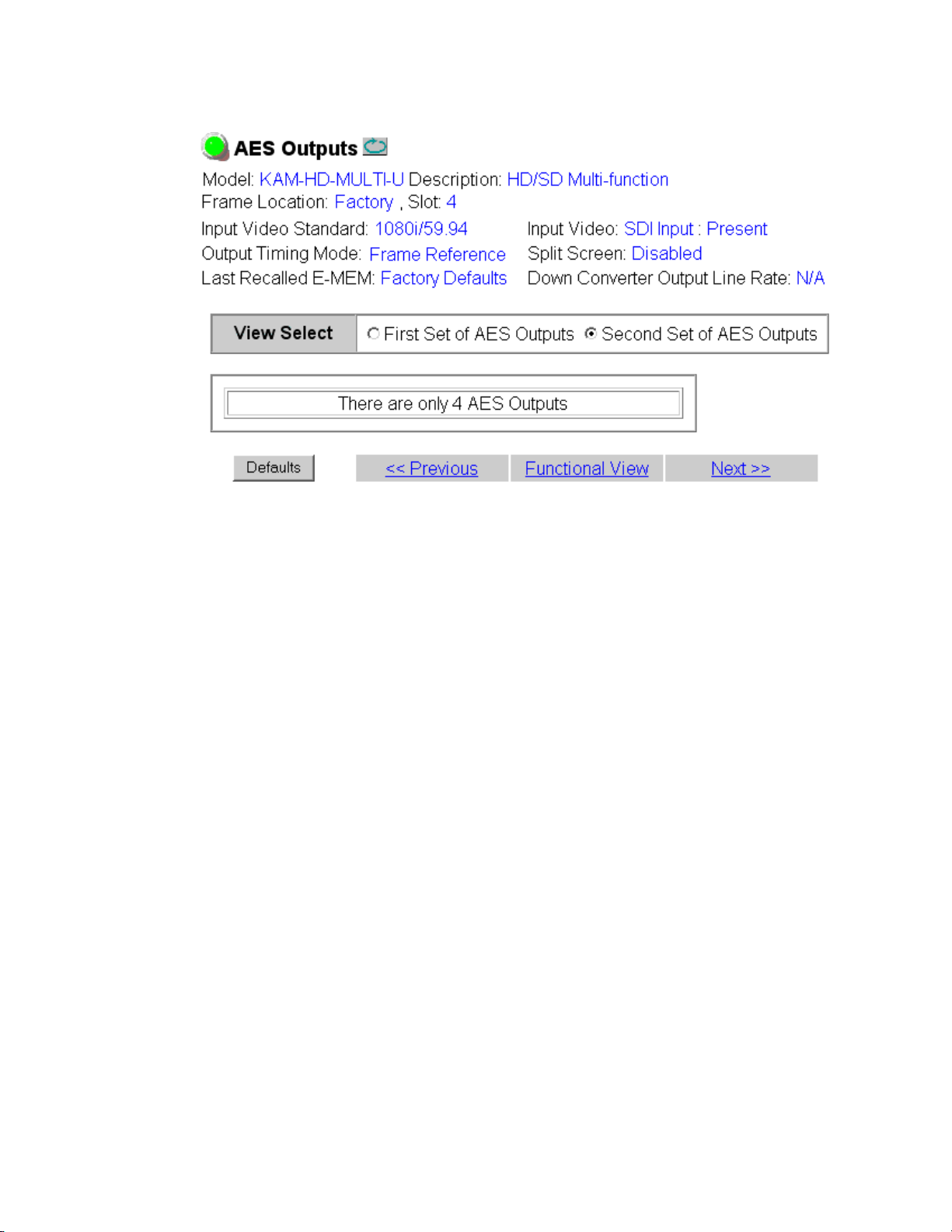
Kameleon HD Links and Web Pages
Figure 51. AES Outputs Web Page – Second Set – 4 In/4 Out
84 KAM-HD-MULTI—Instruction Manual
Page 85
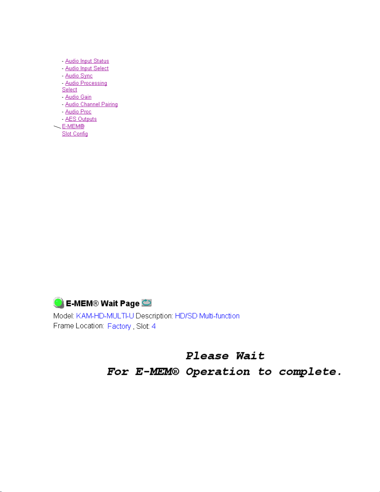
E-MEM Web Page
Use
this
link
The E-MEM web page provides local operations for learning and recalling
configurations into E-MEM registers and audio
operations are also available for saving or loading the learned E-MEM files
to and from a hard disk or other accessible media.
Kameleon HD Links and Web Pages
preset configurations. File
The following functions are available on the E-MEM we
• Five E-MEM registers,
• Two E-MEM view selections:
Recall factory settings button for returning the module to factory defaults
•
(listed in Tab le 4 on page 2 5),
Recall factory names button to return the module to default factory signal
•
names (such as the signal inputs),
• Audio Preset Config button selections to allow presetting an audio con-
figuration for the module.
E-MEM Functions
In Standard view (Figure 53 on page 86), any one of five learned E-MEMs
can be recalled by selecting the corresponding
Operations window. This will place the configuration learned into that
E-MEM into the module.
An E-MEM Wait web page (Fi
formed. This allows any changes in input rate or other module configuration stored in E-MEM to be performed.
b page:
E-MEM 1-5, for storing and recalling setups,
Standard and Advanced,
Recall button in the Local
gure 52) will appear when a recall is per-
Figure 52. E-MEM Wait Web Page
KAM-HD-MULTI—Instruction Manual 85
Page 86

Kameleon HD Links and Web Pages
Figure 53. E-MEM Web Page (Standard View)
86 KAM-HD-MULTI—Instruction Manual
Page 87

Kameleon HD Links and Web Pages
The Advanced View (Figure 54 on page 88) includes a Local Operations
section to Learn and Recall configurations and a File Operations section to
provide a
to and from an external storage location.
To learn an E-MEM:
1. Open the Advanced view.
2. When the configuration is complete for the module, type a descriptive
3. Then, learn the E-MEM to memory by selecting the corresponding Learn
Save to... or Load from... function for saving or loading E-MEM files
name for the configuration into an unused E-MEM register (or
overwrite an existing one) and press
name.
button. All module parameters are learned at once and stored in the
same register. This register is now learned and ready for recall.
Enter on the PC to save the new
KAM-HD-MULTI—Instruction Manual 87
Page 88

Kameleon HD Links and Web Pages
Figure 54. E-MEM Web Page (Advanced View)
88 KAM-HD-MULTI—Instruction Manual
Page 89

Kameleon HD Links and Web Pages
To Save an E-MEM configuration to a file on a hard drive or other accessible media:
1. Select the corresponding Save to... button in the File Operations section.
2. This will bring up a File Download screen (not shown), select Save to
bring up the Save As screen shown in Figure 55.
Figure 55. E-MEM Save to Operation
3. In the Save As dialog box, the file name will default to the
E-MEM name. Browse to the folder where you want to save the
configuration and select
Note You may rename the file during the Save process but the E-MEM name
entered into the Local Operations window will not change on the web page to
match the Save As name. Best practice is to leave the Save As file name the
same as the E-MEM name.
Save. The file saves as a .bin file type.
KAM-HD-MULTI—Instruction Manual 89
Page 90
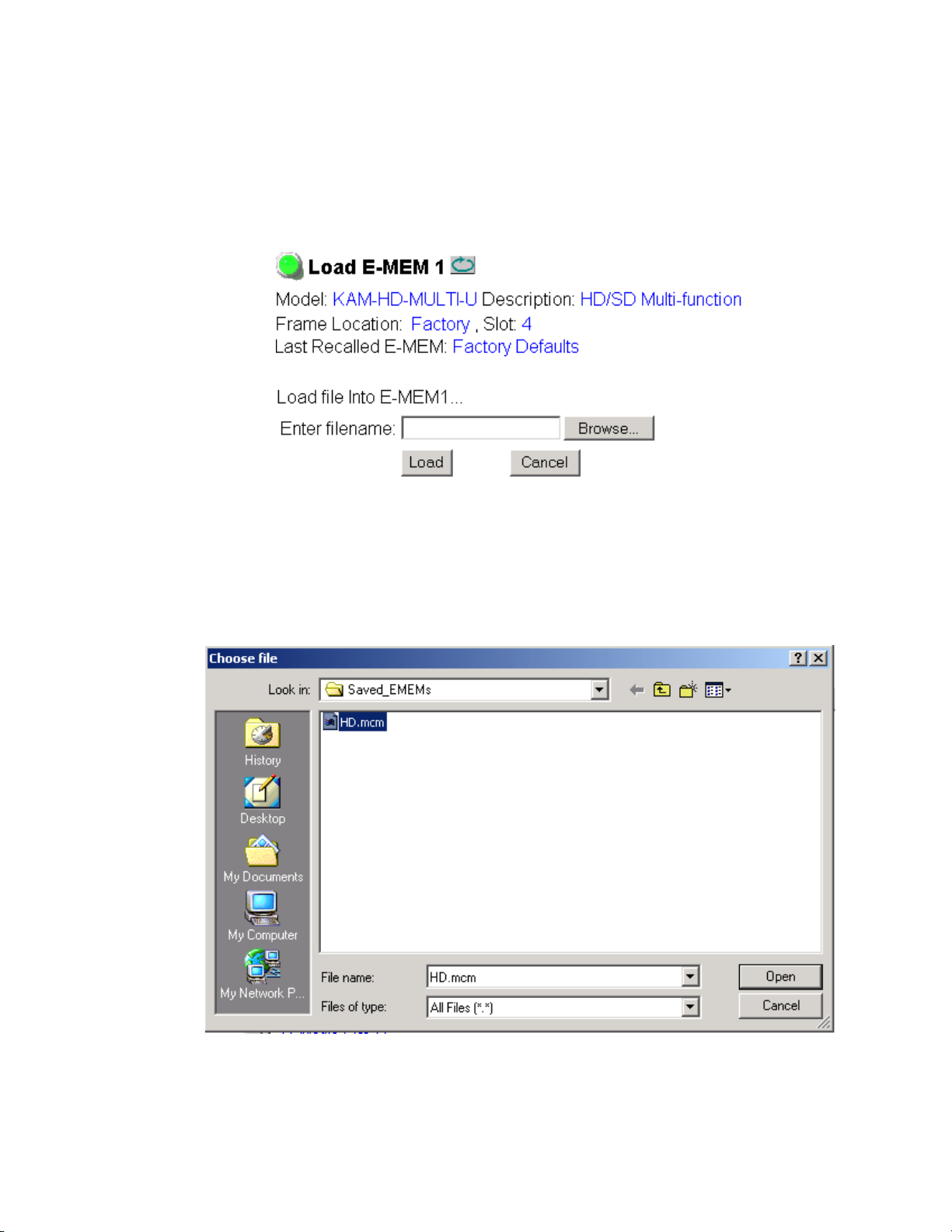
Kameleon HD Links and Web Pages
To load a saved E-MEM from a location:
1. Select the Load from ... button in the File Operations section.
2. This will bring up the Load E-MEM page (Figure 56).
Figure 56. Load E-MEM Page
3. Select Browse to open the Choose File window (Figure 57). Browse to the
location of the file you wish to load and select the file then the
button to load the file or enter the filename and path in the Enter
filename box.
Figure 57. Choose File Window
Open
4. Once the correct path and filename is loaded, select the Load button on
the Load E-MEM page.
90 KAM-HD-MULTI—Instruction Manual
Page 91

Kameleon HD Links and Web Pages
5. This should place the recalled E-MEM file into the corresponding
E-MEM window.
6. Select the corresponding Recall button to invoke this configuration.
Audio Preset Configs
Four Audio Preset Configs buttons (Figure 58) are provided on the bottom
of the E-MEM web page for setting up audio I/O configuration for the rear
module and various audio parameters on the module. A preset configura
tion can be selected depending on the particular audio application required
as described in
describes each preset configuration in detail and explains which configuration is required for different audio applications
The following audio preset configurations are available:
DeEmbed
•
Embed
•
• Universal 8 Ch
• Transcode
Audio Preset Configurations on page 23. This overview
-
Refer to Table 3 on page 24 for a summary of each parameter set when the
Audio Preset Configurations are selected.
Figure 58. Audio Preset Config Buttons on E-MEM Web Page
KAM-HD-MULTI—Instruction Manual 91
Page 92
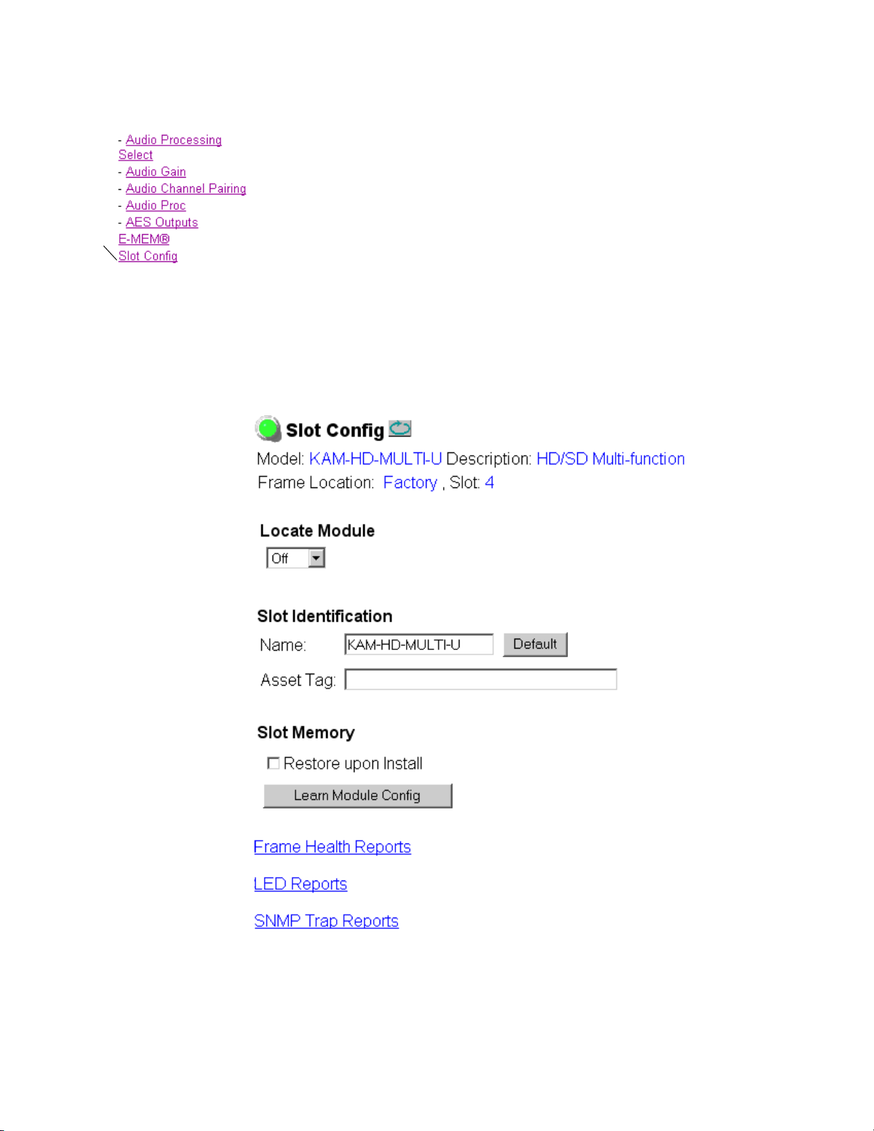
Kameleon HD Links and Web Pages
Use
this
link
Slot Config Web Page
Use the Slot Config web page shown in Figure 59 to perform the following
functions on the module:
•Locate Module
•
Slot Identification
•Slot Memory
• Link to Frame Health Reports 2000NET web page (2000T3 Frames)
• Link to LED Reporting 2000NET web page
• Link to SNMP Trap Reports 2000NET web page
Each of these functions is described on the following pages.
Figure 59. Slot Config Web Page
92 KAM-HD-MULTI—Instruction Manual
Page 93

Locate Module
Selecting Flash from the Locate Module pulldown flashes the yellow COMM
and CONF LEDs on the front of the module so it can be located in the
frame.
Slot Identification
You may identify the module by typing a specific name in the Name field.
The assigned name is stored on the 2000NET module and travels with the
2000NET module if it is moved to another frame. Select
factory default module name.
An asset identification may be entered in the Asset Tag field. This will appear
on the module Status web page and in the NetConfig inventory report.
Slot Memory
The slot configuration for each media module is automatically saved periodically (once an hour) to the 2000NET module in that frame. You may also
select the
ration for this slot. The configuration is saved on the 2000NET module. If
the 2000NET module is removed or powered down, the stored configura
tions are not saved.
Kameleon HD Links and Web Pages
Default to enter the
Learn Module Config button at any time to save the current configu-
-
When the Restore upon Install box has been checked, the current configuration
saved to this slot is saved as slot memory. When the current module is
removed and another module of the same type and software version is
installed, the configuration saved to the 2000NET module will be downloaded to the new module. The box must be checked before the current
module with the saved configuration is removed.
If a different type of module is installed in this slot, a warning message will
state that the original module type has been replaced with another module
type. In this case, a
configuration from the previous module.
Note Uncheck the Restore Upon Install button before downloading new software.
Frame Health Reports Link
Select the Frame Health Reports link to open the 2000NET module Frame
Alarm Reporting web page. This web page allows configuration of the
alarms and warnings that are reported to the external Frame Health Alarm
connector on the rear of the 2000T3 frame (not present on the 2000T1
frame).
Clear button will appear allowing you to clear the stored
KAM-HD-MULTI—Instruction Manual 93
Page 94

Kameleon HD Links and Web Pages
LED Reports Link
Select the LED Reports link to open the 2000NET LED Reporting web page.
Normally, every module in the frame will report to the 2000NET module
any Fault, Signal Loss, Reference Loss, or Config Error conditions. These
conditions will be reflected by the status LEDs on the 2000NET module.
Using this web page, any of these conditions can be disabled from being
reported to the 2000NET module for each individual module in the frame.
SNMP Trap Reports Link
Select the SNMP Trap Reports link to open the 2000NET SNMP Reporting
web page. This link will only be present when SNMP Agent software has
been installed on the 2000NET module. This web page allows configura
tion of what alarms and warnings that are reported to the SNMP management software.
Refer to the 2000NET Instruction Manual for complete details on using the
2000NET web pages.
-
94 KAM-HD-MULTI—Instruction Manual
Page 95

Specifications
Specifications
Table 5. KAM-HD-MULTI-Function Module Specifications
Parameter Value
Serial Digital Input
Number of inputs 1 HD or SD
Signal type 1080i @ 59.94, 50
1080sF @ 24
1080p @ 24
720p @ 59.94, 50
480i @ 59.94 (PAL-B)
576i @ 50 (NTSC)
Connector type 75 ohm BNC
Return loss > 15 dB, from 5 MHz to 1.5 GHz
Auto equalization cable length 300 m (Belden 1694A cable or similar for 270 Mb/s)
100 m (Belden 1694A cable or similar for 1.5 Gb/s)
Serial Digital Outputs
Number of Outputs 3 HD or SD (follows serial digital input)
Signal type Follows serial digital input
Connector type 75 ohm BNC
Return loss > 15 dB, from 5 MHz to 270 MHz
> 10 dB, from 270 MHz to 1.5 GHz
Signal level SDI 800 mV p-p + 10% maximum
Rise and fall time (20-80%) < 270 ps for reclocked HD
400 to 800 ps for SD and bypass mode
Output polarity Non-inverted. all outputs
Output jitter < 0.2 ui (in Frame Sync mode)
AES/EBU Audio Inputs and Outputs
Audio type AES3id-2001
Audio input/output modes 8 In/0 Out
4 In/4 Out
0 In/8 Out
Audio input/output connectors
KAM-HD-MULTI-UR Rear Module 2 (unbalanced D9 connectors with 2 audio breakout cables)
KAM-HD-MULTI-BR Rear Module 4 (balanced dual 3-terminal audio connectors)
Output resolution 20- or 24-bit
KAM-HD-MULTI—Instruction Manual 95
Page 96

Specifications
Tab l e 5 . K A M- HD - MULTI-Function Module Specifications
Parameter Value
Electrical Length
Input to output delay: Default with zero user input delay
In delay mode or in genlock mode with zero input video delay with respect to genlock frame position)
Full-frame mode 1 frame periods in all formats
Minimum delay mode ~ 300 pixel periods in all formats
Input to output delay: User input delay in pixel steps ranging from 0 to 1 frame
In delay mode or in genlock mode with any input video delay with respect to genlock frame position
Full-frame mode 1 frame minus 5 lines to 2 frames minus 5 lines
Minimum delay mode ~ 300 pixels to 1 frame
Power
Power dissipation 22 W
Mechanical
Frame type 2000T1DNG or 2000T3NG Kameleon frame
Environmental
Operating temperature Refer to Kameleon 2000 frame specifications
Operating humidity 0 to 90%, non-condensing
1
The User input delay is specified as 1 full frame. plus one frame in pixels and lines. The Delay Wrap Position
on the Frame Sync web page roughly indicates what fraction of that last frame of adjustable delay is being used.
Because the input video delay with respect to genlock frame position can vary, the Delay Wrap Position with
respect to User Input Delay will vary.
2
Full Frame Mode always has at least 1 frame minus 5 lines of electrical length.
1
2
The frame phase relationship between the SDI video stream and the analog
reference signal is established according to SMPTE RP 168-2002. This
defines the SDI video frame start occurring N pixel periods before the
frame start of the analog video reference signal. N is defined for each video
format in Tab le 6 .
Table 6. Frame Phase Relationship
Format Standard N
408i59.94 SMPTE 125M-1995 16
576i50 Rec. ITU-R BT.656-4 12
1080i59.94 SMPTE 274M-1998 88
720p59.94 SMPTE 296M-2001 110
1080i50 SMPTE 274M-1998 528
720p50 SMPTE 296M-2001 440
1080sF24 SMPTE 274-1998 638
1080p24 SMPTE 274-1998 638
96 KAM-HD-MULTI—Instruction Manual
Page 97

Updating Software
Software updating is done using the NetConfig PC application option
available free of charge from Grass Valley.
Note Always recall factory default parameters after a software update.
Complete software update instructions are given in the latest release notes
for this product. Release notes are posted with the software files on the ftp
site and on the Thomson Grass Valley web site at this URL:
www.thomsongrassvalley.com/docs/modular
Updating Software
KAM-HD-MULTI—Instruction Manual 97
Page 98

Service
8341_08r1
F1
Fuse: 2 A FAST, 125 V
J1
JP3
Voltage
Test Points
+12V
+5V
+2.5V
R10
-2.7V
+2.5V
+1.5V
TP 2
GND
-5V
+3.3V
-12V
GRASS VALLEY SD/HD MULTIFUNCTION MODULE 671-6514 –
Service
The Kameleon HD modules make extensive use of surface-mount technology and programmed parts to achieve compact size and adherence to
demanding technical specifications. Circuit modules should not be ser
-
viced in the field unless directed otherwise by Customer Service.
If your module is not operating correctly, proceed as follows:
• Check frame and module power and signal present LEDs.
• Verify power at the voltage testpoints at the front of the module and
check Fuse F1 if no voltage is detected (Figure 60).
• Check for presence and quality of input signals.
• Verify that source equipment is operating correctly.
• Check cable connections.
Refer to Figure 9 on page 16 for the location of PWR LED and Tab le 1 on
page 16 for proper LED indications.
If the module is still not operating correctly, replace it with a known good
spare and return the faulty module to a designated Grass Valley repair
depot. Call your Grass Valley representative for depot location.
Refer to the Contacting Grass Valley at the front of this document for the
Grass Valley Customer Service Information number.
Figure 60. Test Point and Fuse Locations
98 KAM-HD-MULTI—Instruction Manual
Page 99

Index
Numerics
2000GEN module 10
2000NET module
requirements
10
A
AES C/U/V Bit Pass Through
AES Outputs web page
MUX web page 65
overview 20
summary table 28, 30
AES Error detection 66
AES Output Resolution
MUX web page
summary table 28, 30
AES outputs
cabling
selecting 81
summary table 30
AES Outputs web page 81
audio
breakout cables
capability summary 20
channel pairing
clipping indicator 75
delay (sync) adjustments
gain adjustments
input sources 19
inputs
outputs
overview 19
14
controls
summary table 30
remote control
summary table 29
remote control
summary table 30
cabling
defining 69
status 66
cabling
77
14
14
65
14
72
75
81
paths overview 21
presence indicator 75
Preset Configuration 14
Preset Configurations
buttons on E-MEM web page
overview 23
processing
summary table
web page controls 80
Audio Channel Pairing web page 77
Audio disruption processing 72
Audio Gain web page 75
Audio Input Select web page 69
Audio Input Status web page 66
Audio Proc web page 79
Audio Processing Select web page 74
Audio Sync web page 72
Auto Blue
summary table
Auto Freeze
summary table
auto tracking
remote control
summary table 28
29
26
26
72
91
B
breakout cables 14
C
cabling
input
14
outputs 14
Clear button 93
Coarse adjust button
overview
color correction
summary table
web page control 58
Color Correction web page 58
34
27
KAM-HD-MULTI — Instruction Manual 99
Page 100

Index
color saturation
remote control
summary table 27
COMM LED 16
CONF (configuring) LED 16
configuration
factory default
overview 18
Remote, GUI 19
control panel
Newton Control Panel
summary table 19
60
16
25
D
Data
connector
delay wrap position 55
documentation online 4
14
E
EDH insertion
remote controls
summary table 28
embedded audio
group deletion
E-MEM
advanced view
description 85
load from file 90
save to file 89
standard view 85
web page 85
E-MEM Wait web page 85
65
62
87
F
factory defaults
Recall factory names
recall on E-MEM web page 85
summary table 25
FAQ database 4
FAULT LED 16
fault messages 39
Fiber IF
connector
14
85
Fine adjust button
overview
frame
1 RU
3 RU 11
Frame Health Reporting 93
frame sync
remote controls
summary table 26
Frame Sync web page 54
Frame Sync web page (HD or SD) 54
frequently asked questions 4
Functional View web page 50
fuse 98
34
11
54
G
gamma correction
remote controls
summary table 27
graphical user interface (GUI) 36
Grass Valley web site 4
group insertion (multiplexing)
renote control
summary table 28
58
63
H
HD video
input format selection
proc amp 27, 60
HD Video In web page 53
HD Video Proc web page 60
horizontal timing
remote control
summary table 26
hue
remote control
summary table 27
54
60
25, 47, 48
I
I/O Config web page 43
input
cabling
specifications 95
14
100 KAM-HD-MULTI — Instruction Manual
 Loading...