

Page 1
Kameleon Series
MULTI-FUNCTION MODULES
Instruction Manual
SOFTWARE VERSION 5.0.1
071817304
OCTOBER 2005
Page 2

Contacting Grass Valley
Region Voice Fax Address Web Site
North America (800) 547-8949
Support: 530-478-4148
Pacific Operations +852-2585-6688
Support: 852-2585-6579
U.K., Asia, Middle East +44 1753 218 777 +44 1753 218 757
France +33 1 45 29 73 00
Germany, Europe +49 6150 104 782 +49 6150 104 223
Copyright © Thomson Broadcast and Media Solutions All rights reserved.
Grass Valley Web Site
The www.thomsongrassvalley.com web site offers the following:
Online User Documentation — Current versions of product catalogs, brochures,
data sheets, ordering guides, planning guides, manuals, and release notes
in .pdf format can be downloaded.
FAQ Database — Solutions to problems and troubleshooting efforts can be
found by searching our Frequently Asked Questions (FAQ) database.
Sales: (530) 478-3347
Support: (530) 478-3181
+852-2802-2996
Grass Valley
P.O. Box 599000
Nevada City, CA 95959-7900
USA
www.thomsongrassvalley.com
Software Downloads — Software updates, drivers, and patches can be down-
loaded.
2 Kameleon Series Instruction Manual
Page 3

Preface
About This Manual
This manual describes the features of a specific 2000 Series module in the
Kameleon Media Processing System. As part of this module family, it is
subject to Safety and Regulatory Compliance described in the 2000 Series
frame and power supply documentation (see the Kameleon 2000 Series
Frames Instruction Manual).
Kameleon Series Instruction Manual 3
Page 4

Preface
4 Kameleon Series Instruction Manual
Page 5

Contents
Preface. . . . . . . . . . . . . . . . . . . . . . . . . . . . . . . . . . . . . . . . . . . . . . . . . . . . . . . . . . . . . . . . . . . . . 3
Kameleon Series
Multi-function Modules
About This Manual . . . . . . . . . . . . . . . . . . . . . . . . . . . . . . . . . . . . . . . . . . . . . . . . . . . . . 3
. . . . . . . . . . . . . . . . . . . . . . . . . . . . . . . . . . . . . . . . . . . . . . . . . . . 9
Introduction . . . . . . . . . . . . . . . . . . . . . . . . . . . . . . . . . . . . . . . . . . . . . . . . . . . . . . . . . . . 9
Quickstart Guide . . . . . . . . . . . . . . . . . . . . . . . . . . . . . . . . . . . . . . . . . . . . . . . . . . . . . . 12
Installation . . . . . . . . . . . . . . . . . . . . . . . . . . . . . . . . . . . . . . . . . . . . . . . . . . . . . . . . . . . 14
Frame Capacity . . . . . . . . . . . . . . . . . . . . . . . . . . . . . . . . . . . . . . . . . . . . . . . . . . . . . 14
Module Placement in the Kameleon Frame. . . . . . . . . . . . . . . . . . . . . . . . . . . . . . 15
Cabling . . . . . . . . . . . . . . . . . . . . . . . . . . . . . . . . . . . . . . . . . . . . . . . . . . . . . . . . . . . . 20
KAM-AA-R Configurations . . . . . . . . . . . . . . . . . . . . . . . . . . . . . . . . . . . . . . . . . 21
KAM-MIX-R Configurations . . . . . . . . . . . . . . . . . . . . . . . . . . . . . . . . . . . . . . . . 22
KAM-AES-R Configurations . . . . . . . . . . . . . . . . . . . . . . . . . . . . . . . . . . . . . . . . 23
KAM-AA-AES-UR Configurations . . . . . . . . . . . . . . . . . . . . . . . . . . . . . . . . . . . 25
KAM-AA-MIX-BR Configurations . . . . . . . . . . . . . . . . . . . . . . . . . . . . . . . . . . . 27
KAM-AA-MIX-UR Configurations. . . . . . . . . . . . . . . . . . . . . . . . . . . . . . . . . . . 29
Power Up . . . . . . . . . . . . . . . . . . . . . . . . . . . . . . . . . . . . . . . . . . . . . . . . . . . . . . . . . . . . 31
Operation Indicator LEDs . . . . . . . . . . . . . . . . . . . . . . . . . . . . . . . . . . . . . . . . . . . . 32
Configuration and Adjustments . . . . . . . . . . . . . . . . . . . . . . . . . . . . . . . . . . . . . . . . . 33
Configuration Summary. . . . . . . . . . . . . . . . . . . . . . . . . . . . . . . . . . . . . . . . . . . . . . 33
Newton Control Panel Configuration . . . . . . . . . . . . . . . . . . . . . . . . . . . . . . . . . . 39
Web Browser Interface . . . . . . . . . . . . . . . . . . . . . . . . . . . . . . . . . . . . . . . . . . . . . . . 40
Web Page Operations and Functional Elements. . . . . . . . . . . . . . . . . . . . . . . . . . 42
Status and Identification Header. . . . . . . . . . . . . . . . . . . . . . . . . . . . . . . . . . . . . 42
Initial Configuration Process Overview. . . . . . . . . . . . . . . . . . . . . . . . . . . . . . . . . 43
KAM-AV and KAM-SD Links and Web Pages . . . . . . . . . . . . . . . . . . . . . . . . . . . . 44
Status Web Page. . . . . . . . . . . . . . . . . . . . . . . . . . . . . . . . . . . . . . . . . . . . . . . . . . . . . 46
Color-coded Status Indicators and Links . . . . . . . . . . . . . . . . . . . . . . . . . . . . . . 46
Status/Front Module Properties . . . . . . . . . . . . . . . . . . . . . . . . . . . . . . . . . . . . . 46
Submodule Properties. . . . . . . . . . . . . . . . . . . . . . . . . . . . . . . . . . . . . . . . . . . . . . 46
Warning/Fault Summary. . . . . . . . . . . . . . . . . . . . . . . . . . . . . . . . . . . . . . . . . . . 49
Input/Output Configuration Web Page . . . . . . . . . . . . . . . . . . . . . . . . . . . . . . . . 50
I/O Config Page Elements . . . . . . . . . . . . . . . . . . . . . . . . . . . . . . . . . . . . . . . . . . 56
Functional View Web Page . . . . . . . . . . . . . . . . . . . . . . . . . . . . . . . . . . . . . . . . . . . 58
Composite In Web Page . . . . . . . . . . . . . . . . . . . . . . . . . . . . . . . . . . . . . . . . . . . . . . 60
Video Input Status . . . . . . . . . . . . . . . . . . . . . . . . . . . . . . . . . . . . . . . . . . . . . . . . . 60
Settings for Standard 525/625 . . . . . . . . . . . . . . . . . . . . . . . . . . . . . . . . . . . . . . . 60
3D Decoder Control. . . . . . . . . . . . . . . . . . . . . . . . . . . . . . . . . . . . . . . . . . . . . . . . 61
VBI Decode Web Page for Composite Input . . . . . . . . . . . . . . . . . . . . . . . . . . . . . 64
SDI Input Web Page . . . . . . . . . . . . . . . . . . . . . . . . . . . . . . . . . . . . . . . . . . . . . . . . . 66
Current State. . . . . . . . . . . . . . . . . . . . . . . . . . . . . . . . . . . . . . . . . . . . . . . . . . . . . . 66
Reported Errors . . . . . . . . . . . . . . . . . . . . . . . . . . . . . . . . . . . . . . . . . . . . . . . . . . . 66
DEMUX Web Page . . . . . . . . . . . . . . . . . . . . . . . . . . . . . . . . . . . . . . . . . . . . . . . . . . 68
Kameleon Series Instruction Manual 5
Page 6

Contents
Video Input Select Web Page . . . . . . . . . . . . . . . . . . . . . . . . . . . . . . . . . . . . . . . . . 69
View Setting . . . . . . . . . . . . . . . . . . . . . . . . . . . . . . . . . . . . . . . . . . . . . . . . . . . . . . 69
Video Selection Settings . . . . . . . . . . . . . . . . . . . . . . . . . . . . . . . . . . . . . . . . . . . . 69
Output Timing Selection . . . . . . . . . . . . . . . . . . . . . . . . . . . . . . . . . . . . . . . . . . . 70
Advanced VBI Configuration . . . . . . . . . . . . . . . . . . . . . . . . . . . . . . . . . . . . . . . 72
Frame Sync Web Page . . . . . . . . . . . . . . . . . . . . . . . . . . . . . . . . . . . . . . . . . . . . . . . 74
Timing Adjustment. . . . . . . . . . . . . . . . . . . . . . . . . . . . . . . . . . . . . . . . . . . . . . . . 74
Freeze Mode Selection . . . . . . . . . . . . . . . . . . . . . . . . . . . . . . . . . . . . . . . . . . . . . 74
Video Processing Web Page . . . . . . . . . . . . . . . . . . . . . . . . . . . . . . . . . . . . . . . . . . 76
Video Processing Controls. . . . . . . . . . . . . . . . . . . . . . . . . . . . . . . . . . . . . . . . . . 76
Clipping Controls . . . . . . . . . . . . . . . . . . . . . . . . . . . . . . . . . . . . . . . . . . . . . . . . . 78
Advanced View . . . . . . . . . . . . . . . . . . . . . . . . . . . . . . . . . . . . . . . . . . . . . . . . . . . 78
Reset To Default . . . . . . . . . . . . . . . . . . . . . . . . . . . . . . . . . . . . . . . . . . . . . . . . . . 78
MUX Web Page . . . . . . . . . . . . . . . . . . . . . . . . . . . . . . . . . . . . . . . . . . . . . . . . . . . . . 80
Group Deletion . . . . . . . . . . . . . . . . . . . . . . . . . . . . . . . . . . . . . . . . . . . . . . . . . . . 80
Group Replacement . . . . . . . . . . . . . . . . . . . . . . . . . . . . . . . . . . . . . . . . . . . . . . . 83
VBI Encode Web Page for Composite Output . . . . . . . . . . . . . . . . . . . . . . . . . . . 85
VBI Data Line Configuration for SDI Output. . . . . . . . . . . . . . . . . . . . . . . . . . . . 87
Video Composite Out Web Page . . . . . . . . . . . . . . . . . . . . . . . . . . . . . . . . . . . . . . 89
Signal Setup . . . . . . . . . . . . . . . . . . . . . . . . . . . . . . . . . . . . . . . . . . . . . . . . . . . . . . 90
Cross Color Removal . . . . . . . . . . . . . . . . . . . . . . . . . . . . . . . . . . . . . . . . . . . . . . 90
Chrominance Removal. . . . . . . . . . . . . . . . . . . . . . . . . . . . . . . . . . . . . . . . . . . . . 90
Burst Removal . . . . . . . . . . . . . . . . . . . . . . . . . . . . . . . . . . . . . . . . . . . . . . . . . . . . 90
Output Video Adjustments . . . . . . . . . . . . . . . . . . . . . . . . . . . . . . . . . . . . . . . . . 90
SDI Out Web Page . . . . . . . . . . . . . . . . . . . . . . . . . . . . . . . . . . . . . . . . . . . . . . . . . . 92
Output Delay Coarse . . . . . . . . . . . . . . . . . . . . . . . . . . . . . . . . . . . . . . . . . . . . . . 92
Analog Audio Inputs Web Page. . . . . . . . . . . . . . . . . . . . . . . . . . . . . . . . . . . . . . . 93
Input . . . . . . . . . . . . . . . . . . . . . . . . . . . . . . . . . . . . . . . . . . . . . . . . . . . . . . . . . . . . 94
Name. . . . . . . . . . . . . . . . . . . . . . . . . . . . . . . . . . . . . . . . . . . . . . . . . . . . . . . . . . . . 94
Maximum Input Level . . . . . . . . . . . . . . . . . . . . . . . . . . . . . . . . . . . . . . . . . . . . . 94
Signal Present. . . . . . . . . . . . . . . . . . . . . . . . . . . . . . . . . . . . . . . . . . . . . . . . . . . . . 94
Clipping . . . . . . . . . . . . . . . . . . . . . . . . . . . . . . . . . . . . . . . . . . . . . . . . . . . . . . . . . 94
AES Inputs Web Page . . . . . . . . . . . . . . . . . . . . . . . . . . . . . . . . . . . . . . . . . . . . . . . 95
Input . . . . . . . . . . . . . . . . . . . . . . . . . . . . . . . . . . . . . . . . . . . . . . . . . . . . . . . . . . . . 95
Name. . . . . . . . . . . . . . . . . . . . . . . . . . . . . . . . . . . . . . . . . . . . . . . . . . . . . . . . . . . . 95
Signal State . . . . . . . . . . . . . . . . . . . . . . . . . . . . . . . . . . . . . . . . . . . . . . . . . . . . . . . 95
Sample Rate . . . . . . . . . . . . . . . . . . . . . . . . . . . . . . . . . . . . . . . . . . . . . . . . . . . . . . 95
Mode . . . . . . . . . . . . . . . . . . . . . . . . . . . . . . . . . . . . . . . . . . . . . . . . . . . . . . . . . . . . 96
Emphasis . . . . . . . . . . . . . . . . . . . . . . . . . . . . . . . . . . . . . . . . . . . . . . . . . . . . . . . . 96
Data . . . . . . . . . . . . . . . . . . . . . . . . . . . . . . . . . . . . . . . . . . . . . . . . . . . . . . . . . . . . . 96
AES Errors Detected . . . . . . . . . . . . . . . . . . . . . . . . . . . . . . . . . . . . . . . . . . . . . . . 96
Audio Input Select Web Page . . . . . . . . . . . . . . . . . . . . . . . . . . . . . . . . . . . . . . . . . 97
Input Stream Select . . . . . . . . . . . . . . . . . . . . . . . . . . . . . . . . . . . . . . . . . . . . . . . . 98
Status. . . . . . . . . . . . . . . . . . . . . . . . . . . . . . . . . . . . . . . . . . . . . . . . . . . . . . . . . . . . 98
Sample Rate Convert . . . . . . . . . . . . . . . . . . . . . . . . . . . . . . . . . . . . . . . . . . . . . . 98
Loss of Signal Reporting . . . . . . . . . . . . . . . . . . . . . . . . . . . . . . . . . . . . . . . . . . . 98
Reporting . . . . . . . . . . . . . . . . . . . . . . . . . . . . . . . . . . . . . . . . . . . . . . . . . . . . . . . . 98
AES Errors . . . . . . . . . . . . . . . . . . . . . . . . . . . . . . . . . . . . . . . . . . . . . . . . . . . . . . . 98
Audio Channel Pairing Web Page . . . . . . . . . . . . . . . . . . . . . . . . . . . . . . . . . . . . 100
Audio Sync Web Page . . . . . . . . . . . . . . . . . . . . . . . . . . . . . . . . . . . . . . . . . . . . . . 101
Audio Proc Web Page . . . . . . . . . . . . . . . . . . . . . . . . . . . . . . . . . . . . . . . . . . . . . . 102
Pair Selection . . . . . . . . . . . . . . . . . . . . . . . . . . . . . . . . . . . . . . . . . . . . . . . . . . . . 102
Audio Gain. . . . . . . . . . . . . . . . . . . . . . . . . . . . . . . . . . . . . . . . . . . . . . . . . . . . . . 102
Output Processing. . . . . . . . . . . . . . . . . . . . . . . . . . . . . . . . . . . . . . . . . . . . . . . . 102
6 Kameleon Series Instruction Manual
Page 7

Selecting Audio Mode. . . . . . . . . . . . . . . . . . . . . . . . . . . . . . . . . . . . . . . . . . . . . 103
Selecting Output Resolution. . . . . . . . . . . . . . . . . . . . . . . . . . . . . . . . . . . . . . . . 103
Analog Audio Outputs Web Page . . . . . . . . . . . . . . . . . . . . . . . . . . . . . . . . . . . . 105
AES Outputs Web Page . . . . . . . . . . . . . . . . . . . . . . . . . . . . . . . . . . . . . . . . . . . . . 106
E-MEM Configuration Web Page . . . . . . . . . . . . . . . . . . . . . . . . . . . . . . . . . . . . . 107
File Operations . . . . . . . . . . . . . . . . . . . . . . . . . . . . . . . . . . . . . . . . . . . . . . . . . . . 109
Slot Configuration Web Page. . . . . . . . . . . . . . . . . . . . . . . . . . . . . . . . . . . . . . . . . 112
Slot Identification. . . . . . . . . . . . . . . . . . . . . . . . . . . . . . . . . . . . . . . . . . . . . . . . . 112
Locate Module . . . . . . . . . . . . . . . . . . . . . . . . . . . . . . . . . . . . . . . . . . . . . . . . . . . 112
Slot Memory . . . . . . . . . . . . . . . . . . . . . . . . . . . . . . . . . . . . . . . . . . . . . . . . . . . . . 112
Frame Health Reports Link . . . . . . . . . . . . . . . . . . . . . . . . . . . . . . . . . . . . . . . . 113
SNMP Trap Reports Link . . . . . . . . . . . . . . . . . . . . . . . . . . . . . . . . . . . . . . . . . . 114
Software Updating . . . . . . . . . . . . . . . . . . . . . . . . . . . . . . . . . . . . . . . . . . . . . . . . . . . 116
Acquiring Software . . . . . . . . . . . . . . . . . . . . . . . . . . . . . . . . . . . . . . . . . . . . . . . . . 116
NetConfig Software . . . . . . . . . . . . . . . . . . . . . . . . . . . . . . . . . . . . . . . . . . . . . . . 116
Kameleon Software . . . . . . . . . . . . . . . . . . . . . . . . . . . . . . . . . . . . . . . . . . . . . . . 117
Updating Software With NetConfig. . . . . . . . . . . . . . . . . . . . . . . . . . . . . . . . . . . 118
NetConfig Upgrade Procedure . . . . . . . . . . . . . . . . . . . . . . . . . . . . . . . . . . . . . 118
Specifications . . . . . . . . . . . . . . . . . . . . . . . . . . . . . . . . . . . . . . . . . . . . . . . . . . . . . . . . 121
Service. . . . . . . . . . . . . . . . . . . . . . . . . . . . . . . . . . . . . . . . . . . . . . . . . . . . . . . . . . . . . . 128
Troubleshooting. . . . . . . . . . . . . . . . . . . . . . . . . . . . . . . . . . . . . . . . . . . . . . . . . . . . 128
Contents
Index . . . . . . . . . . . . . . . . . . . . . . . . . . . . . . . . . . . . . . . . . . . . . . . . . . . . . . . . . . . . . . . . . . . . . 129
Kameleon Series Instruction Manual 7
Page 8

Contents
8 Kameleon Series Instruction Manual
Page 9

Kameleon Series Multi-function Modules
Introduction
This manual contains a Quickstart guide supported by references to the
complete manual and supporting documents (see Quickstart Guide on
page 12). Detailed installation, power up, and configuration information
follows the Quickstart Guide.
The Kameleon Series multi-function modules are for use in 2000 Series
Kameleon Frames. They are designed for facilities that receive multiple
feeds that need considerable audio and video processing. They are particularly well suited for broadcasters and cable facilities that need to manipulate or add audio channels to multiple program streams.
Note Kameleon operation requires 2000NET Network Interface Module hardware
revision 01A1 or greater with software version 4.0.0 or greater.
Kameleon systems installed in the 2000T3N frame require the 2000FAN fan
sled (refer to Figure 7 on page 18).
Kameleon offers processing modules that provide a flexible, compact
system of conversion, multiplexing, timing and signal processing functions
for standard definition, analog and digital, video and audio.
The Kameleon Modular Series consists of the following:
• Two versions of the front processing module are available,
• SD – SDI video processor with SDI Video I/O and AES/EBU
and/or analog audio I/O (with submodules), and
• AV – Composite or SDI video I/O and AES/EBU or analog audio
I/O (with submodules).
Kameleon Series Instruction Manual 9
Page 10

Introduction
Standard front processing module functions include:
• 3D video decoding (KAM-AV only),
• Up to 8 channels of audio A/D or D/A conversion (with submodules),
• Video and audio synchronization,
• 8 channels of audio embedding/de-embedding,
• Audio remapping to specific I/O,
• AES/EBU sample rate conversion,
• Video and audio processing amplifiers,
• Video and audio test signal generators,
• Individual Analog and Digital video timing controls, and
• Powerful VBI (vertical blanking interval) processing.
•Six types of rear I/O modules are available:
• KAM-AA-R Analog Audio Rear module,
• KAM-MIX-R Mixed Audio Rear module,
• KAM-AES-R AES Audio Rear module,
• KAM-AA-AES-UR Rear module,
• KAM-AA-MIX-BR Rear module, and
• KAM-AA-MIX-UR Rear module.
• Two audio conversion submodules that can be installed on the processing module,
• Four-channel Analog to Digital Conversion Submodule (ADC), and
• Four-channel Digital to Analog Conversion Submodule (DAC).
Note Frame synchronization requires a 2000GEN Genlock Reference Module
installed in the 2000 Series Kameleon Frame.
A front and rear module pair are required. The front processing modules
provide the signal processing power while the rear module determines the
specific I/O connections (refer to Figure 1 on page 11). Separate audio
A-to-D and D-to-A converter submodules may be installed in two slots on
either version of the processing module.
10 Kameleon Series Instruction Manual
Page 11
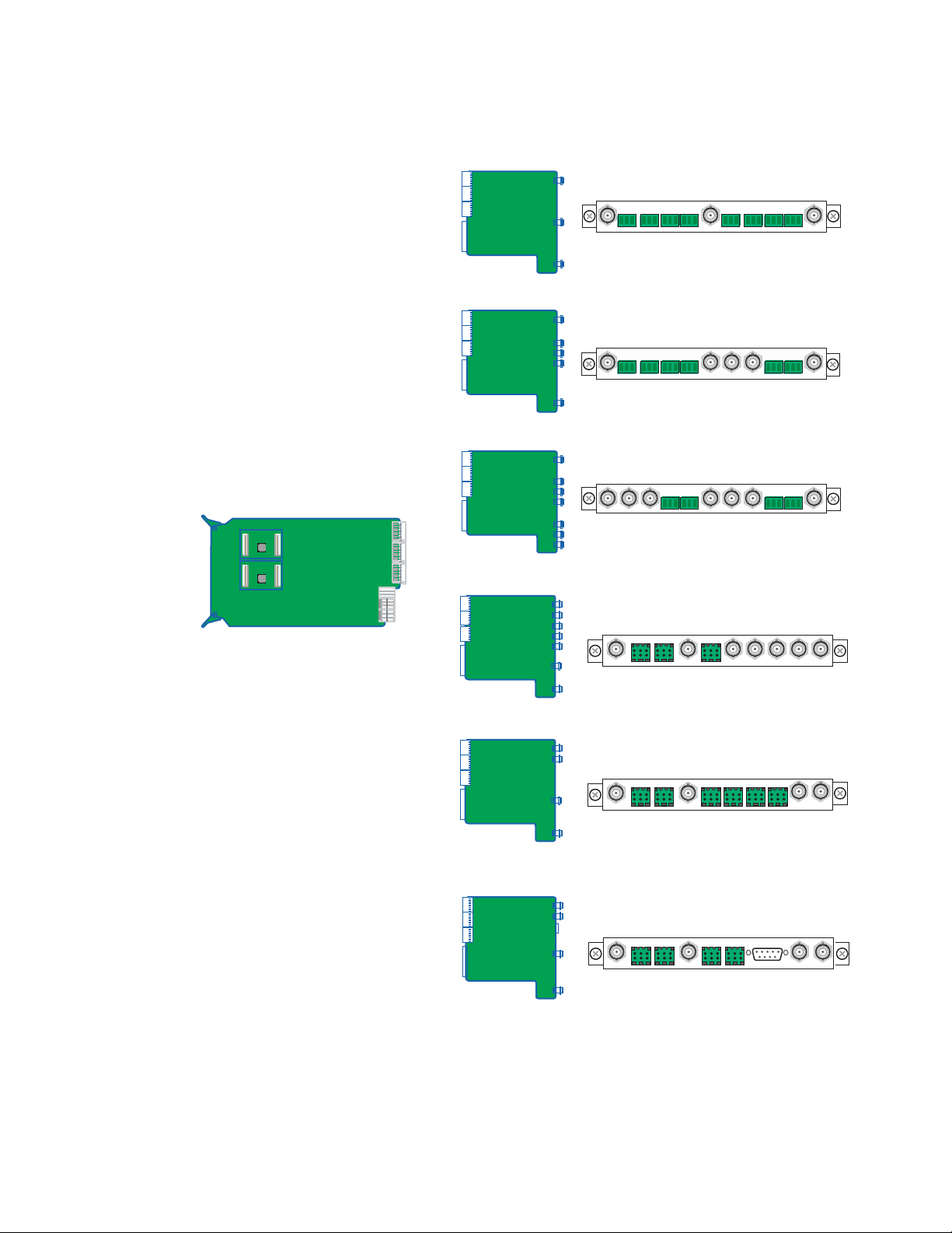
Figure 1. Kameleon Processing and Rear Modules
Processing Module
KAM-SD or KAM-A/V Processor
Introduction
Rear I/O Modules
KAM-AA-R Kameleon Analog Audio Rear Module
KAM-MIX-R Kameleon Mixed Audio Rear Module
KAM-AES-R Kameleon AES Rear Module
KAM-AA-AES-UR Kameleon Analog
AES (Unbalanced) Rear Module
KAM-AA-MIX-BR Kameleon Analog
AES (Balanced) Rear Module
KAM-AA-MIX-UR Kameleon Analog
AES (Unbalanced) Rear Module
8173-07r1
Kameleon Series Instruction Manual 11
Page 12

Quickstart Guide
Quickstart Guide
1. Install modules in the frame.
2. Connect the frame to the network and navigate the web browser to the
3. Navigate to the module you would like to configure and click on the
4. Navigate to I/O Configuration page to configure AES/EBU ports as:
Install the rear I/O Module. Install submodules on the front Processing
Module if needed (page 17) then install the module in the frame.
frame.
See the 2000NET Instruction Manual for information on configuring
your frame IP address and connecting to the network.
appropriate slot to open configuration links.
• Inputs or outputs, and
• Balanced or unbalanced (see page 50).
Click on the
uration also allows you to assign names for all of the module’s
incoming and outgoing signals. Assigning easily recognized names
will help later in the configuration process.
5. Connect signal cables.
Configuration will be easier if all of the input signals are connected at
this time.
6. Configure the Video Input Select page (see page 69).
Configure the video source and the output timing source. If you have
the 2000GEN reference installed in the frame and want the Kameleon
to work as a frame sync, set the output timing source to Frame Reference. If not, set the output timing source to Video In.
7. Configure the DEMUX (demultiplex) page (see page 68).
If you are de-multiplexing audio out of the video signal,
figured next. The audio Demux page is used to extract digital audio
groups from incoming SDI video for processing. These audio groups
become inputs to the Audio Input Select page.
8. Configure the remaining audio/video pages.
I/O Config page link on the left side of the page. I/O Config-
DEMUX is con-
Navigate to the
or page 59 for the KAM-SD). Starting from the left, use the block
diagram links to access and configure the different blocks for the
desired operation by clicking on any link in a block.
12 Kameleon Series Instruction Manual
Functional View web page (see page 58 for the KAM-AV
Page 13

Quickstart Guide
9. Configure vertical blanking interval (VBI) control.
To support data carried on particular lines, the Kameleon controls
certain functions within the vertical blanking interval (VBI) and on
some of the active video lines.
We refer to active video lines that are used to carry data as “Data Lines”.
Clicking the
Select
page (page 69) displays the controls that allow you to specify
which active video lines will be carrying data.
After making selections on this page, use the following pages for configuring the VBI/Data Lines:
VBI Decode – for the composite input (page 64),
•
VBI Encode – for the composite output (page 85), and
•
VBI SDI – for serial digital output (page 87).
•
Advanced (VBI Config) radio button at the top of the Video Input
Kameleon Series Instruction Manual 13
Page 14

Installation
Installation
Frame Capacity
To install the Kameleon modules:
1. Place the passive rear module in a frame slot and tighten the screws on
each side of the rear module,
2. Place the processor module in the corresponding front slot, and
3. Cable the signal ports.
All Kameleon modules can be inserted and removed from a 2000 Series
Kameleon Frame with power on.
Note Remove the front processing module before removing the rear I/O module.
Audio submodules must be installed or removed with the processing module
removed from the frame (processor module powered down).
Kameleon modules can be installed in any 2000 Series frame with a
2000NET interface.
Note For optimum functionality, the 2000NET module should be running software
version 4.0.0 or later.
The one rackunit 2000T1DN (with dual 130W power supplies and 2000NET
module) or 2000T1DNG (with dual 130W power supplies, 2000NET and
2000GEN modules) frames have no Kameleon module capacity limitations.
The three rackunit 2000T3N (single 240W p/s, 2000FAN, and 2000NET
module) and 2000T3NG (single 240W p/s, 2000FAN, 2000NET and
2000GEN modules) frames can be fully populated with Kameleon modules
when the 2000FAN fan sled and two power sleds are installed.
Ta bl e 1 provides the maximum Kameleon module count for frame types.
Table 1. Power, Cooling, and Module Capacity of 2000 Series Kameleon Frames
2000T1DN/NG
Kameleon Frame
Capacity
KAM-SD Module set
KAM-AV Module set
Item
2000T3N/DNG
Kameleon Frame
Capacity
12 4
12 4
14 Kameleon Series Instruction Manual
Page 15
Module Placement in the Kameleon Frame
There are twelve slot locations in both the front and rear of a 3 RU frame
and four slot locations in a 1 RU frame to accommodate 2000 and Kameleon
Series media modules (audio/video signal handling modules).
The Kameleon media modules consist of a two-module set with a processing module and a passive rear module that can be plugged into any of
the frame slot pairs. The rear modules provide the input and output interface connectors.
To install a Kameleon module set in a 2000 Series frame:
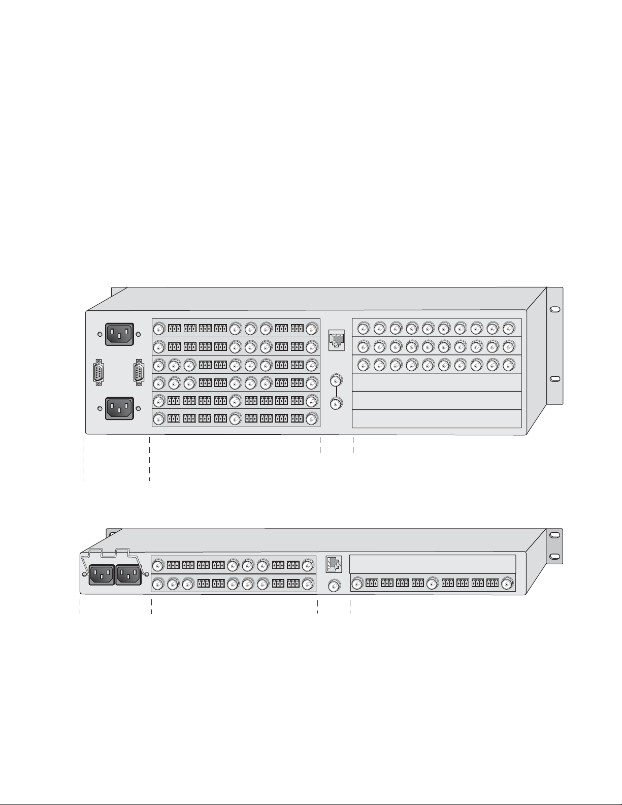
1. Locate a vacant slot in the rear of the 3 RU frame (Figure 2) or the
2000T1DNG frame (Figure 3).
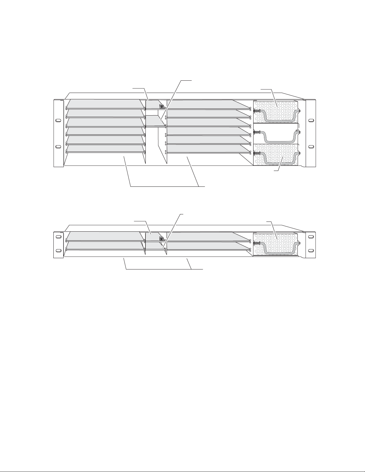
Figure 2. 2000T3NG Frame, Rear View
Installation
Power, frame
configuration,
& frame health
connections
Power connections
Media section
rear slots 7-12
Figure 3. 2000T1DNG Frame, Rear View
Media section
rear slots 3-4
Network
and reference
input connections
1
3
J101
J102
2
4
Network
and reference
input connections
Media section
rear slots 1-6
(with three 2000EMI blanks)
Media section
rear slots 1-2
(with one 2000EMI blank)
8173-27r1
2. Insert the passive rear module into the vacant rear slot of the frame as
illustrated in Figure 4 on page 16.
8173_28
Kameleon Series Instruction Manual 15
Page 16
Installation
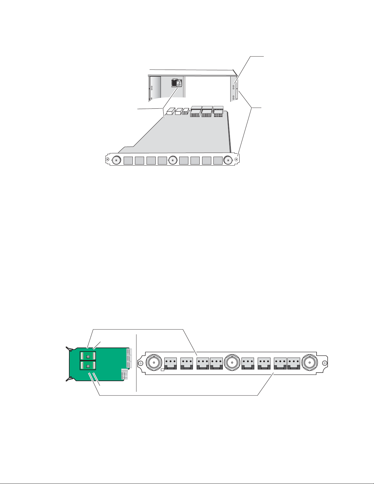
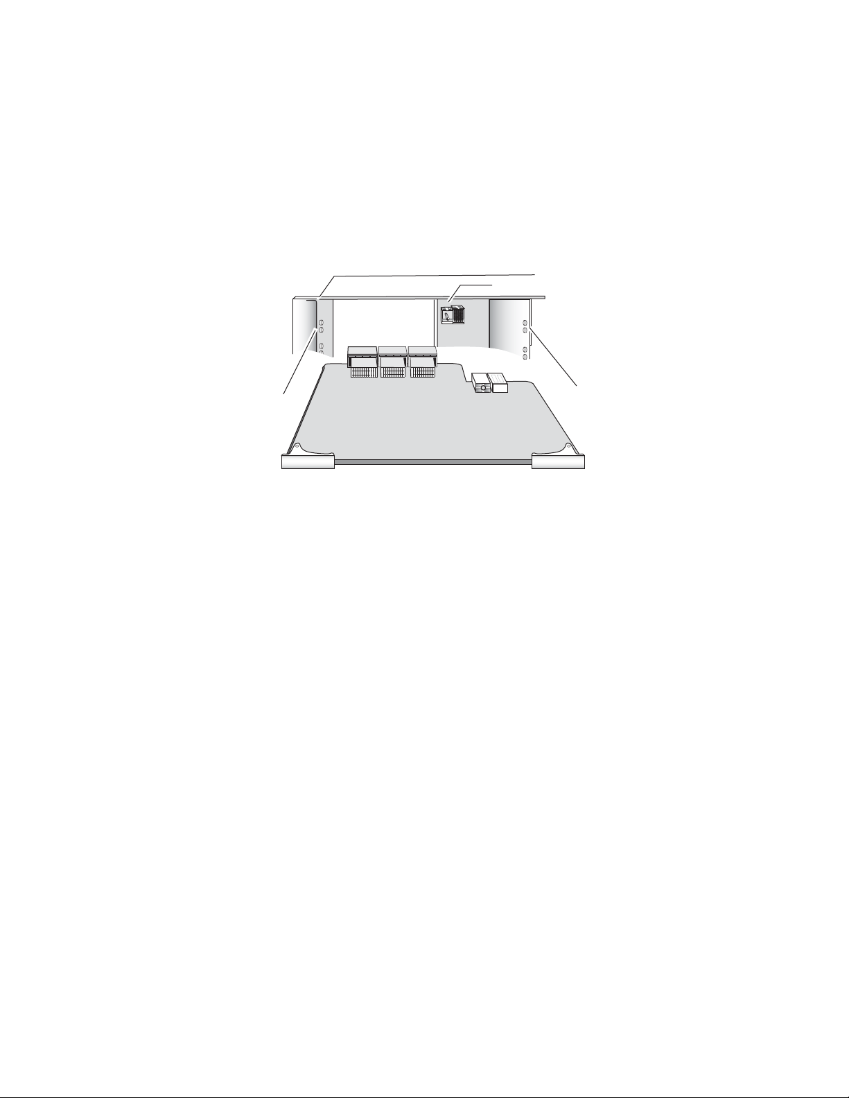
Figure 4. Installing Passive Rear Module
2000 frame (rear view)
Board edge guides
(both sides)
Rear alignment
post and receptacle
KAM passive rear module
Screw lock
(both sides)
3. Verify that the module connector seats properly against the midplane.
4. Using a crossblade screwdriver, tighten the two screw locks to secure
the module in the frame.
5. If an ADC and/or DAC audio submodule option has been ordered, the
submodule will be provided with the front processing media module.
Placement of the submodule depends on the desired audio I/O configuration from the rear module type being used. The installation of the
submodule will determine the functionality of the input and output
audio connectors on each side of the rear module.
8173-05r1
As illustrated in Figure 5, Submodule 1 is wired to the connectors on
the left side of the rear module. Submodule 2 is wired to the right side
connectors.
Figure 5. Submodule/Rear Connector Relationship
Wired to left side connectors
Submodule 1
Submodule 2
Wired to right side connectors
KAM-AA Rear connectors shown,
same relationship for other rear modules
Refer to the rear module cabling information tables for correct placement of the submodules to match your requirements as follows:
16 Kameleon Series Instruction Manual
8173_33r2
Page 17

Installation
• KAM-AA-R – designed for eight-channel analog audio I/O (see
Table 2 on page 21).
• KAM-MIX-R – designed for mixed I/O of two AES/EBU streams
(balanced or unbalanced) and four analog audio channels, (see
Table 3 on page 22).
• KAM-AES-R – designed for eight AES/EBU audio, balanced or
unbalanced I/O connections (see Tab le 4 on pag e 24 ). No submodules are used with this application.
• KAM-AA-AES-UR – designed for mixed I/O of three dual balanced
analog audio inputs or outputs (six channels) and four BNC audio
connections for four streams of AES audio inputs, outputs, or two
inputs and two outputs (see Table 6 on page 26). If the sub-
module(s) need to be installed, refer to Figure 5 on page 16 for the
location of the submodule depending on the application.
• KAM-AA-MIX-BR – designed for mixed I/O of four dual balanced
analog audio inputs or outputs (eight channels) and two dual balanced audio connections for four streams of AES audio which can
be set independently as inputs or outputs (see Table 7 on page 28).
If the submodule(s) needs to be installed, refer to Figure 5 on
page 16 for the location of the submodule depending on the appli-
cation and Figure 6 for installing it onto the module.
• KAM-AA-MIX-UR – designed for mixed I/O of four dual balanced
analog audio inputs or outputs (eight channels) and one Sub-D 9
pin connector for four streams of unbalanced AES audio which can
be set independently as inputs or outputs (see Table 8 on page 30).
If the submodule(s) need to be installed, refer to Figure 5 on page 16
for the location of the submodule depending on the application.
To install a submodule, line up the connectors on the bottom of the submodule with the correct submodule position on the top of the media
module circuit board (Figure 6). Press firmly to seat the submodule and
Figure 6 for installing it onto the module.
After power-up, installation status of the submodule will be reported
on the Status web page as described in Status Web Page on page 46.
Figure 6. Kameleon Submodule Installation
KAM-ADC/DAC submodule
Submodule 1
Submodule 2
8173_31r1
Kameleon Series Instruction Manual 17
Page 18
Installation
6. Locate the corresponding front media slot (1 -12) in the 3 RU frame
frame (Figure 7) or front media (slot 1-4) the 1 RU frame (Figure 8).
Figure 7. 2000T3NG Kameleon Frame, Front Slots
Reference Distribution Slot (15)
Network Slot (13)
Main Power Supply Slot (18)
(1)
(2)
(3)
(4)
(5)
(6)
(13)
(15)
Figure 8. 2000T1DNG Kameleon Frame Front Slots
Reference Distribution Slot (6)
Network Slot (5)
(1)
(2)
(5)
(6)
(7)
(8)
(9)
(10)
(11)
(12)
Secondary Power
Supply Slot (20)
Front Media Slots (1-12)
Power Supply Slot (7)
(3)
(4)
Front Media Slots (1-4)
Fan Sled
Slot (19)
8173-04r1
8039-21
18 Kameleon Series Instruction Manual
Page 19
Installation
7. With the component side up, insert the front processing module in the
corresponding front slot (see Figure 9).
8. Verify that the module connector seats properly against the midplane
and rear module connector.
9. Press firmly on both ejector tabs to seat the module.
Figure 9. Installing Front Media Module
2000 Frame (front view)
Alignment post and receptacle
Board edge
guides
Board edge
guides
8173_08
KAM-SD
Kameleon Series Instruction Manual 19
Page 20

Installation
Cabling
All cabling is done at the corresponding rear module. Six different rear
modules are available for various audio and video I/O configurations.
All modules accept SDI video in and provide SDI video out. Composite
video inputs and outputs are only available with the KAM-AV front
module.
Many audio functions require the use of the audio ADC (analog to digital)
and DAC (digital to analog) conversion submodules installed on the front
module. Use of the submodules depends on the type of rear module and
the audio requirements as described in each rear module cabling section.
Cabling for each type of rear module is illustrated in the figures listed
below:
• KAM-AA-R – see Figure 10 on page 21,
•KAM-MIX-R – see Figure 11 on page 22,
•KAM-AES-R – see Figure 12 on page 23,
• KAM-AA-AES-UR – see Figure 13 on page 25,
• KAM-AA-MIX-BR – see Figure 14 on page 27, and
• KAM-AA-MIX-UR – see Figure 15 on page 29.
Specific signal names are assigned for each connector using the 2000 GUI
using the
I/O Config web page (see Configuration and Adjustments on page 33).
20 Kameleon Series Instruction Manual
Page 21
KAM-AA-R Configurations
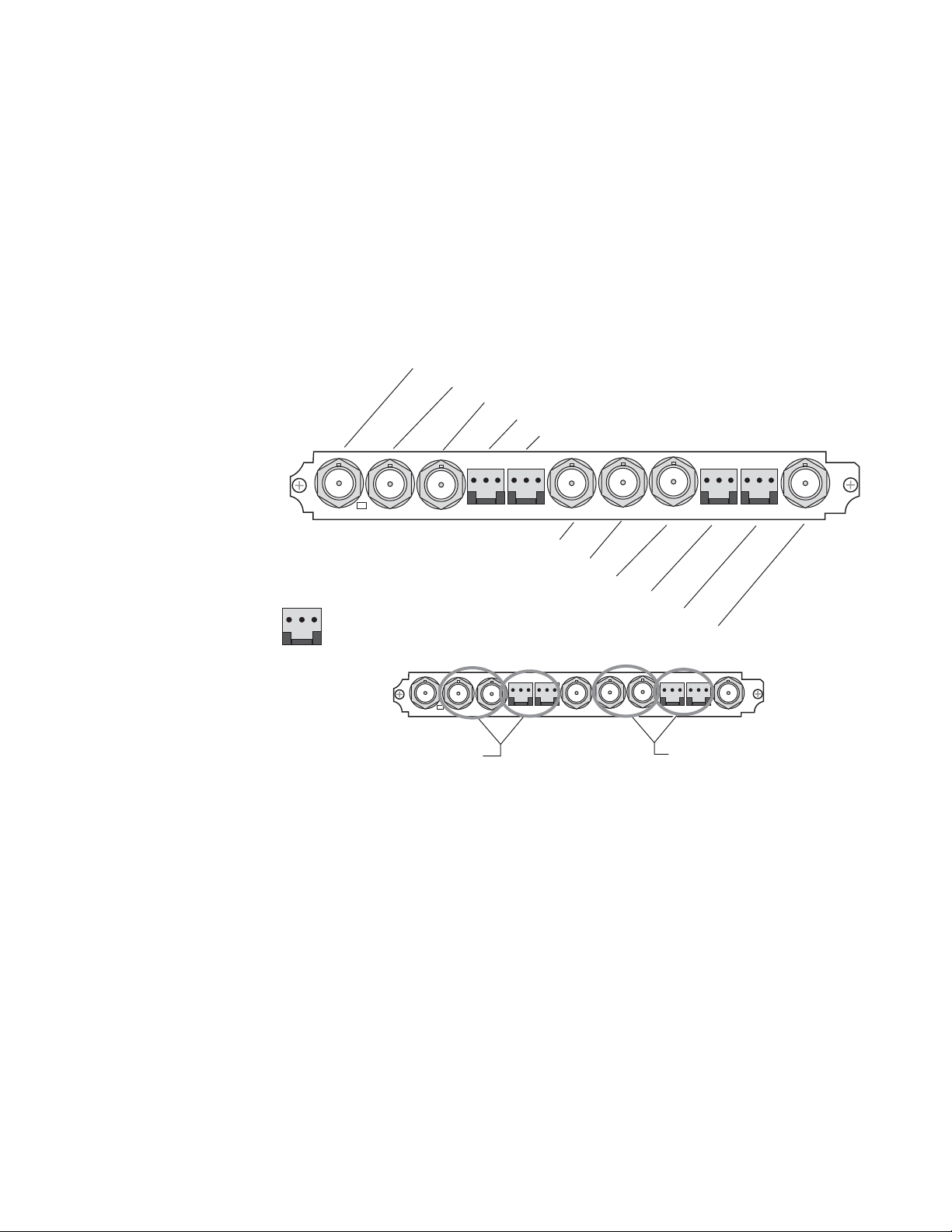
The KAM-AA-R rear I/O module (Figure 10) accepts either SDI or composite video (KAM-AV only). Three video BNC connectors are provided—
one each for video in, composite video out (KAM-AV only), and SDI video
out. Eight three-terminal audio connectors are provided for analog audio
input or output I/O as determined by placement of the audio conversion
submodules.
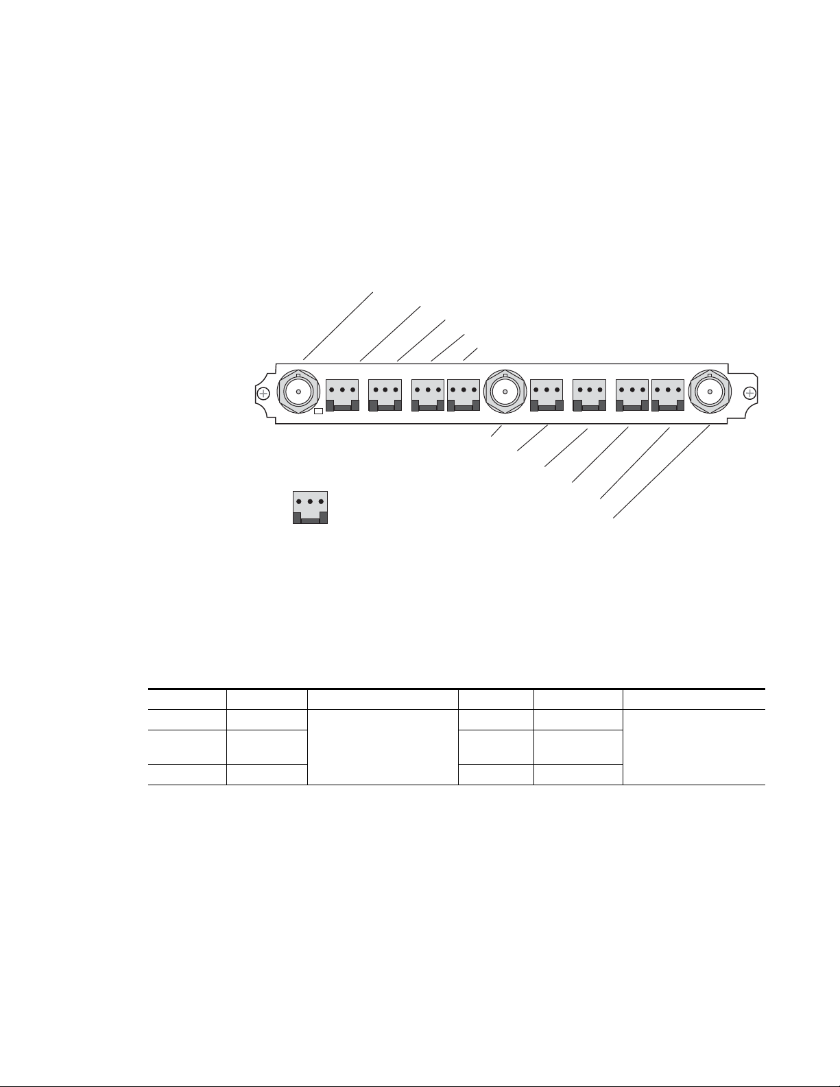
Figure 10. KAM-AA-R Input/Output Connectors
J11 VI, SDI or Composite Video In
Installation
J10 AN AUD1, Analog Audio In/Out
J9 AN AUD2, Analog Audio In/Out
J8 AN AUD3, Analog Audio In/Out
J7 AN AUD4, Analog Audio In/Out
SIG
J11
Connector
AN AUD1 AN AUD2 AN AUD3 AN AUD4 AN AUD5 AN AUD6 AN AUD7 AN AUD8
SIG
Audio
pinout
+ – G
J6 Composite Video Out
J4 AN AUD6, Analog Audio In/Out
J5 AN AUD5, Analog Audio In/Out
J3 AN AUD7, Analog Audio In/Out
J2 AN AUD8, Analog Audio In/Out
CVO
J1 SDO, SDI Video Out
SDO
Ta bl e 2 provides the various audio input and output I/O configurations
based on the positioning of the audio ADC and DAC submodules and the
available video outputs. Figure 5 on page 16 illustrates the relationship of
submodule to rear connector for KAM rear modules. Submodule installation is shown in Figure 6 on page 17.
Table 2. KAM-AA-R I/O Configurations
Submodule 1 Submodule 2 Video Input Audio Inputs Audio Outputs Video Output
A to D A to D
1
D to A D to A
A to D D to A 4 analog 4 analog
1
Only KAM-AV modules support composite video I/O.
1 SDI or Composite
(J11)
8 analog None
Demux from
SDI input
8 analog
1 SDI (J1) and
1 Composite1 (J6)
2900
PRM-7
8173-09r2
J1J6 J2J3J5 J4J7J8J9J10
Kameleon Series Instruction Manual 21
Page 22
Installation
KAM-MIX-R Configurations
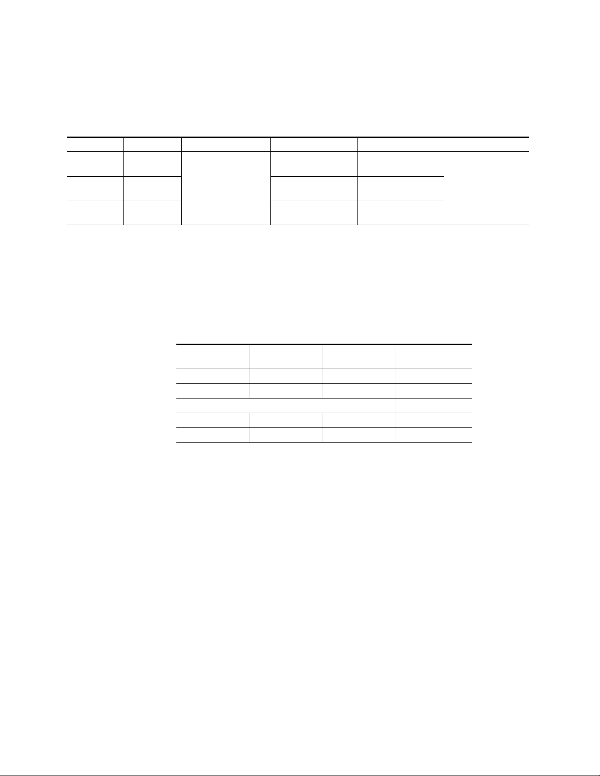
The KAM-MIX-R rear I/O module (Figure 11) accepts either SDI or com-
posite video (KAM-AV only). Five BNC connectors are provided—three for
video and two for unbalanced AES/EBU I/O. Six three-terminal audio
connectors are provided— four for analog audio I/O and two for analog or
balanced AES/EBU I/O.
Figure 11. KAM-MIX-R Input/Output Connectors
J11 VI, SDI or Composite Video In
J10 AN AUD1, Analog Audio In/Out
J9 AN AUD2, Analog Audio In/Out
J8 AN AUD3, Analog Audio In/Out
J7 AN AUD4, Analog Audio In/Out
SIG
J11
AN AUD1 AN AUD2 AN AUD3 AN AUD4 AES 1 AES 2
SIG
CVO AES
AES
1
2
SDO
J1J6 J2J3J5 J4J7J8J9J10
J6 CVO, Composite Video Out
J5 AES1, Unbalanced AES/EBU Audio In/Out
J4 AES2, Unbalanced AES/EBU Audio In/Out
Audio
Connector
pinout
+ – G
J3 AES1, Balanced AES/EBU Audio In/Out
J2 AES2, Balanced AES/EBU Audio In/Out
J1 SDO, SDI Video Out
AES connector use:
Paired connectors,
must use either
balanced or unbalanced
Ta bl e 3 provides the various audio input and output I/O configurations
based on the positioning of the audio ADC and DAC submodules and the
available video outputs. Figure 5 on page 16 illustrates the relationship of
submodule to rear connector for KAM rear modules. Submodule installation is shown in Figure 6 on page 17
2900
PRM-7
8173-09r2
Table 3. KAM-MIX-R I/O Configurations
Submodule 1 Submodule 2 Video Input Audio Inputs Audio Outputs Video Output
A to D None
D to A None
A to D None 4 analog
1 SDI or Composite
(J11)
D to A None None
1
Only KAM-AV modules support composite video I/O.
4 analog, 2 AES/EBU
balanced or unbalanced
2 AES/EBU balanced or
1
unbalanced
None
4 analog
2 AES/EBU balanced or
unbalanced
4 analog, 2 AES/EBU
balanced or unbalanced
1 SDI (J1) and
1 Composite
1
(J6)
22 Kameleon Series Instruction Manual
Page 23
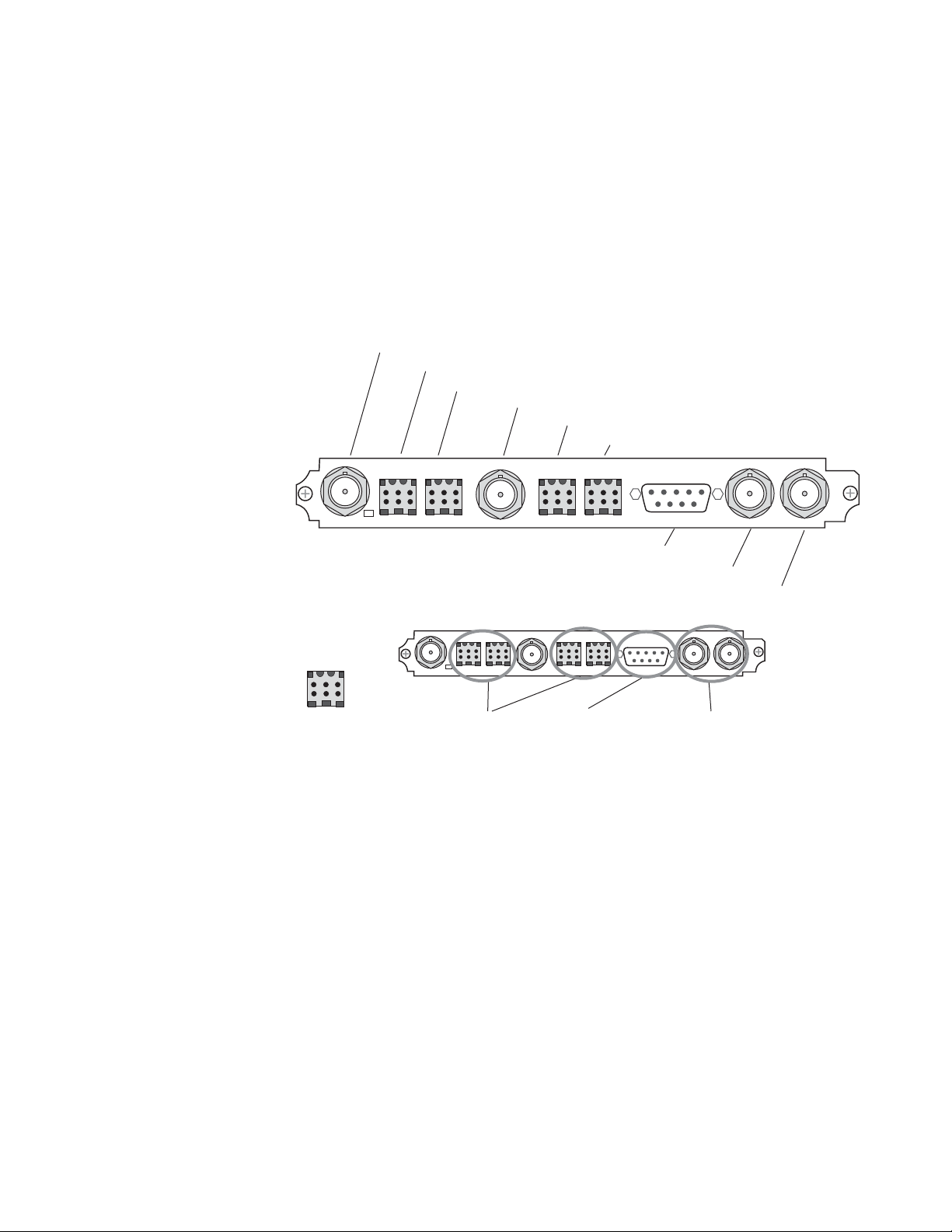
KAM-AES-R Configurations
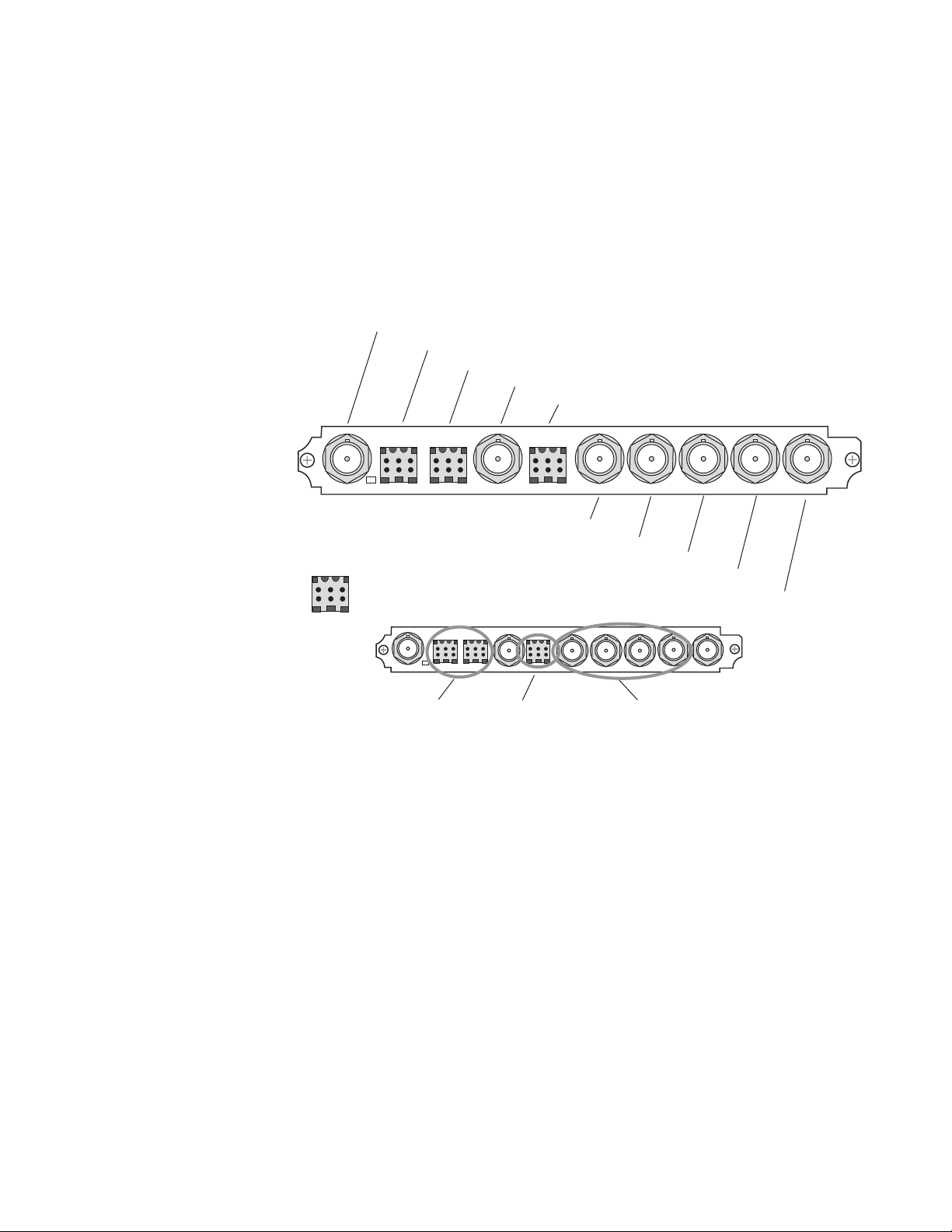
The KAM-AES-R rear I/O module accepts either SDI or composite video
(KAM-AV only). Seven BNC connectors are provided—three for video and
four for unbalanced AES/EBU I/O. Four three-terminal audio connectors
are provided for AES/EBU balanced audio I/O. AES/EBU connectors are
configured in pairs as shown in Figure 12.
Note Only the selected AES outputs are valid. Unconfigured AES outputs are
invalid and should not be used.
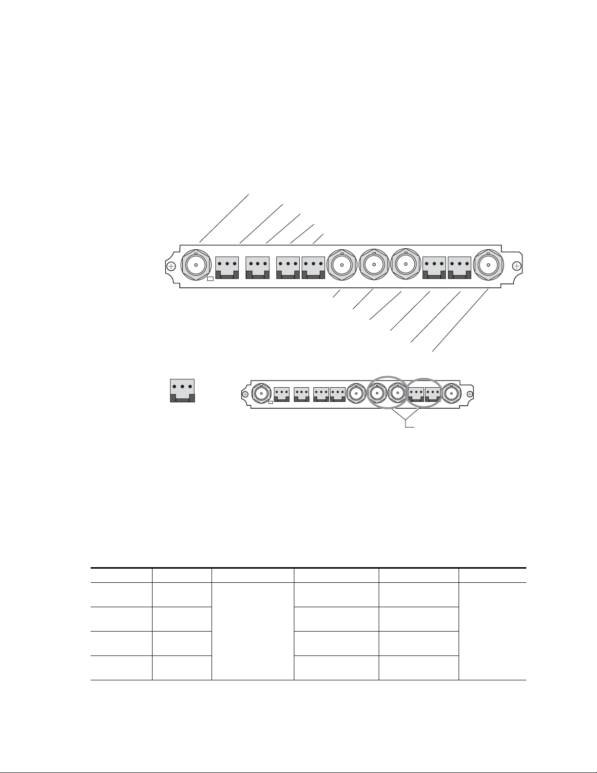
Figure 12. KAM-AES-R Input/Output Connectors
J11 VI, SDI or Composite Video In
SIG
AES
AES
1
2
J10 AES1, Unbalanced AES/EBU Audio In/Out
J9 AES2, Unbalanced AES/EBU Audio In/Out
J8 AES1, Balanced AES/EBU Audio In/Out
J7 AES2, Balanced AES/EBU Audio In/Out
CVO AES
AES 2AES 1 AES 4AES 3
AES
3
4
Installation
SDO
2900
PRM-7
J11
Audio
Connector
pinout
+ – G
SIG
J6 CVO, Composite Video Out
J5 AES3, Unbalanced AES/EBU Audio In/Out
J4 AES4, Unbalanced AES/EBU Audio In/Out
J3 AES3, Balanced AES/EBU Audio In/Out
J2 AES4, Balanced AES/EBU Audio In/Out
AES connector use:
Paired connectors,
must use either
balanced or unbalanced
J1 SDO, SDI Video Out
Paired connectors,
must use either
balanced or unbalanced
8173-11r1
J1J6 J2J3J5 J4J7J8J9J10
Kameleon Series Instruction Manual 23
Page 24
Installation
Ta bl e 4 provides the various audio input and output I/O configurations
and the available video outputs. Submodules are not used in these configurations.
Tab l e 4 . K A M- AE S -R I/O Configurations
Submodule1 Submodule 2 Video Input Audio Inputs Audio Outputs Video Output
None None
None None None
None None
1
Only KAM-AV modules support composite video I/O.
1 SDI or Composite1
(J11)
4 balanced or unbalanced
AES/EBU
2 balanced or unbalanced
AES/EBU
None
4 balanced or unbalanced
AES/EBU
2 balanced or unbalanced
AES/EBU
1 Composite
Tab le 5 lists the active and inactive connections for the KAM-AES-R
module when the Balanced or Unbalanced mode is selected.
Only the selected AES outputs are valid. Unconfigured AES outputs are invalid and
should not be used.
1 SDI (J1‘) and
1
(J6)
Tab l e 5 . K A M- AE S-R AES/EBU Connector Selections
Channel Pair Mode Active Connectors
AES 1 & AES 2 Unbalanced J10 and J9 J8 and J7
AES 1 & AES 2 Balanced J8 and J7 J10 and J9
AES 3 & AES 4 Unbalanced J5 and J4 J3 and J2
AES 3 & AES 4 Balanced J3 and J2 J5 and J4
Connectors
Inactive
24 Kameleon Series Instruction Manual
Page 25
KAM-AA-AES-UR Configurations
The KAM-AA-AES-UR rear I/O module (Figure 13) accepts either SDI or
composite video (KAM-AV only). Three BNC connectors are provided for
video—one video input, one composite output (KAM-AV only), and one
SDI video output. Three dual terminal audio connectors are provided for
analog audio input or output I/O. Four BNCs are provided for unbalanced
input or output AES I/O.
Figure 13. KAM-AA-AES-UR Input/Output Connectors
J10 VI, SDI or Composite Video In
J9 Analog Audio, In or Out
J8 Analog Audio, In or Out
Installation
J7 CVO, Composite Video Out
J6 Analog Audio, In or Out
V1
J10
Dual Audio
Connector
pinout
+ – G
Analog Audio Analog Audio
SIG
J5, Unbalanced AES/EBU, In or Out
Connector Use:
Analog Audio:
All Inputs or
All Outputs
CVO
J4, Unbalanced AES/EBU, In or Out
Analog Audio:
All Inputs or
All Outputs
J3, Unbalanced AES/EBU, In or Out
J2, Unbalanced AES/EBU, In or Out
J1 SDO, SDI Video Out
Unbalanced AES: (Four Streams)
All Inputs, All Outputs or independently
selectable as inputs or outputs.
SDOAES AES AES AES
KAM-AA
AES-UR
8173-36
J1J2J3J4J5J6J7J8J9
Kameleon Series Instruction Manual 25
Page 26

Installation
Ta bl e 6 provides the various audio input and output I/O configurations
and the video outputs for the KAM-AA-AES-UR rear module. Analog
audio input or output configuration depends on the positioning of the
audio ADC and DAC submodules.
Any number of audio inputs can be configured but there is a limit of four
audio output pairs with any configuration.
Table 6. KAM-AA-AES -UR I/O Configurations
Submodule 1
A to D A to D
A to D D to A
A to D None 2 dual analog inputs (J8 and J9)
None A to D 1 dual analog input (J6
D to A D to A
D to A A to D
D to A None 2 dual analog outputs (J8 and j9)
None D to A 1 dual analog output (J6
None None None
1
There may be any number of audio inputs but there is a limit of four output audio pairs with any configuration.
2
Only KAM-AV modules support composite video I/O.
3
Analog Audio connector J6 supports only Analog Audio Channels 1 and 2.
Submodule
2
Video Input
1 SDI or Composite
(J10)
2
2 dual analog outputs (J8 and J9) and
Analog Audio
Inputs/Outputs
3 dual analog inputs
3
(J6
, J8, and J9)
2 dual analog inputs (J8 and J9)
and 1 dual analog output (J6
3 dual analog outputs
3
, J8, and J9)
(J6
1 dual analog input (J63)
1
3
)
3
3
)
selectable as all inputs,
selectable as inputs or
I/O Config web page
)
AES Audio
Inputs/Outputs
4 AES/EBU
unbalanced
BNCs J2-J5
all outputs,
or independently
outputs on the
1
Video Output
1 SDI (J1) and 1
Composite
2
(J7)
26 Kameleon Series Instruction Manual
Page 27
KAM-AA-MIX-BR Configurations
The KAM-AA-MIX-BR rear I/O module (Figure 14) accepts either SDI or
composite video (KAM-AV only). Four BNC connectors are provided for
video—one video input, one composite output (KAM-AV only), and two
SDI video outputs. Four dual terminal audio connectors are provided for
analog audio input or output I/O. Two dual terminal audio connectors are
provided for balanced input or output AES/EBU I/O.
Figure 14. KAM-AA-MIX-BR Input/Output Connectors
J10 VI, SDI or Composite Video In
J9, Analog Audio, In or Out
J8, Analog Audio, In or Out
Installation
J7, CVO, Composite Video Out
J6, Analog Audio, In or Out
J5, Analog Audio, In or Out
V1
J10
Dual Audio
Connector
pinout
+ – G
Analog Audio Analog Audio
SIG
CVO
J4, Balanced AES/EBU, In or Out
J3, Balanced AES/EBU, In or Out
Connector Use:
Analog Audio:
All Inputs or
All Outputs
AES
J5J6J7J8J9
J4
J2, SDO, SDI Video Out
J1, SDO, SDI Video Out
Balanced AES/EBU:
(Four Streams)
2 Identical SDI
Video Outputs
All Inputs, All Outputs
or independently selectable
as inputs or outputs.
SDO SDO
KAM-AA
MIX-BR
8173-37
J1J2J3
Kameleon Series Instruction Manual 27
Page 28

Installation
Ta bl e 7 provides the various audio input and output I/O configurations
and the video outputs for the KAM-AA-MIX-BR rear module. Analog
audio input or output configuration depends on the positioning of the
audio ADC and DAC submodules. Figure 5 on page 16 illustrates the relationship of submodule to rear connector for KAM rear modules.
AES/EBU audio input or output configuration is set by configuring the
connector as an input or output on the I/O Config web page (Figure 27 on
page 54).
Any number of audio inputs can be configured but there is a limit of four
audio output pairs with any configuration.
Table 7. KAM-AA-MIX-BR I/O Configurations
Submodule 1
A to D A to D
A to D D to A
D to A D to A
D to A A to D
A to D None 2 dual Analog inputs (J8 and J9)
None A to D 2 dual Analog inputs (J5 and J6)
D to A None 2 dual Analog outputs (J8 and j9)
None D to A 2 dual Analog outputs (J5 and J6)
None None None
1
There may be any number of audio inputs but there is a limit of four output audio pairs with any configuration.
2
Only KAM-AV modules support composite video I/O.
Submodule
2
Video Input
1 SDI or Composite
(J10)
and 2 dual Analog outputs (J5 and J6)
2
2 dual Analog outputs (J8 and J9) and
Analog Audio
Inputs/Outputs
4 dual Analog inputs
(J5, J6, J8, and J9)
2 dual Analog inputs (J8 and J9)
4 dual Analog outputs
(J5, J6, J8, and J9)
2 dual Analog inputs (J5 and J6)
1
AES Audio
Inputs/Outputs
4 AES/EBU (J3 and J4)
balanced I/O indepen-
dently selectable as
inputs or outputs on
the I/O Config web
page.
Video Output
2 SDI (J1 and J2),
1 Composite (J7)
2
28 Kameleon Series Instruction Manual
Page 29
KAM-AA-MIX-UR Configurations
The KAM-AA-MIX-UR rear I/O module (Figure 15) accepts either SDI or
composite video (KAM-AV only). Four BNC connectors are provided for
video—one video input, one composite output (KAM-AV only), and two
SDI video outputs. Four dual terminal audio connectors are provided for
analog audio I/O. A 9-pin Sub D connector is provided for unbalanced
input or output AES I/O from a breakout cable that is included with the
module.
Figure 15. KAM-AA-MIX-UR Input/Output Connectors
J10 VI, SDI or Composite Video In
J9 Analog Audio, In or Out
J8 Analog Audio, In or Out
Installation
J7 CVO, Composite Video Out
J6 Analog Audio, In or Out
J5 Analog Audio, In or Out
V1
J10
Dual Audio
Connector
pinout
+ – G
Analog Audio Analog Audio
SIG
Connector Use:
Analog Audio:
All Inputs or
All Outputs
CVO
J3 Unbalanced AES/EBU Audio In or Out
AES
J2 SDO, SDI Video Out
J1 SDO, SDI Video Out
Unbalanced AES/EBU:
(Four Sreams)
All Inputs, All Outputs
or independently selectable
as input or output.
SDO SDO
2 Identical SDI
Video Outputs
KAM-AA
MIX-UR
8173-35
J1J2J3J5J6J7J8J9
Kameleon Series Instruction Manual 29
Page 30

Installation
Ta bl e 8 provides the various audio input and output I/O configurations
and the video outputs for the KAM-AA-MIX-UR rear module. Analog
audio input or output configuration depends on the positioning of the
audio ADC and DAC submodules. Figure 5 on page 16 illustrates the relationship of submodule to rear connector for KAM rear modules.
AES/EBU audio input or output configuration is set by configuring the
connector as an input or output on the I/O Config web page (Figure 28 on
page 55).
Any number of audio inputs can be configured but there is a limit of four
audio output pairs with any configuration.
Table 8. KAM-AA-MIX-UR I/O Configurations
Submodule 1
A to D A to D
A to D D to A
D to A D to A
D to A A to D
A to D None 2 dual Analog inputs (J8 and J9)
None A to D 2 dual Analog inputs (J5 and J6)
D to A None 2 dual Analog outputs (J8 and j9)
None D to A 2 dual Analog outputs (J5 and J6)
None None None
1
There may be any number of audio inputs but there is a limit of four output audio pairs with any configuration.
2
Only KAM-AV modules support composite video I/O.
Submodule
2
Video Input
1 SDI or Composite
(J10)
and 2 dual Analog outputs (J5 and J6)
2
2 dual Analog outputs (J8 and J9) and
Analog Audio
Inputs/Outputs
4 dual Analog inputs
(J5, J6, J8, and J9)
2 dual Analog inputs (J8 and J9)
4 dual Analog outputs
(J5, J6, J8, and J9)
2 dual Analog inputs (J5 and J6)
1
AES Audio
Inputs/Outputs
4 AES/EBU (J3)
unbalanced
streams from break-
out cable indepen-
dently selectable as
inputs or outputs on
I/O Config web page.
Video Output
2 SDI (J1 and J2),
1 Composite (J7)
2
30 Kameleon Series Instruction Manual
Page 31

Power Up
Power Up
The front LED indicators are illustrated in Figure 16.
Figure 16. Front and Rear Module Indicator LEDs
FAULT – Red diagnostic LED is off during normal operation
COMM – Yellow LED on during remote control communication
CONF – Yellow LED on when module is initializing or processing control data
PWR – Green diagnostic LED on indicates power OK
Processor Module
Front Edge
Passive Rear
Module
For factory use.
D1 D2 D3 D4 D5 D6 D7 D8
Ejector Tab
Signal Present LED
GND – Digital ground
8173_12
A green Signal Present LED can be seen on the Passive Rear Module (PRM)
on all model types when a valid input signal is present.
Kameleon Series Instruction Manual 31
Page 32

Power Up
Operation Indicator LEDs
Ta bl e 9 provides a complete list of possible operating conditions and the
resulting indicator status.
A red FAULT LED indicates an error situation. Tab le 9 describes signal
output and LED indications for the various input/reference combinations
and user settings.
Table 9. Indicator LEDs and Conditions Indicated
LED Indication Condition
Normal operation
Module has detected internal fault
One of the inputs is missing or is wrong standard
Errors present in SDI and/or AES/EBU input
No activity on frame communication bus
Module Location command received from a remote control system
Activity present on the frame communication bus
Module is in normal operating mode
Module Location command received from a remote control system
Module is initializing, changing operating modes or updating firmware. (When solid on along with
Fault LED on, board has failed to load data.)
No power to module or module’s DC/DC converter failed
Normal operation, module is powered
Fault
(red)
COMM
(yellow)
CONF
(yellow)
PWR
(green)
Off
On continuously
Long flash
Short flash
Off
Three flash/off pattern
Short flash
Off
Three flash/off pattern
On continuously
Off
On continuously
Note The yellow COMM and CONF LEDs are used for the module location function
that is enabled using the 2000NET GUI. The module location function causes
these LEDs to repeatedly flash concurrently three times followed by an off
state of 900 ms duration (see Slot Configuration Web Page on page 112).
32 Kameleon Series Instruction Manual
Page 33

Configuration and Adjustments
KAM-AV/SD configuration and monitoring can be performed using a web
browser GUI interface or a networked Newton Control Panel. This section
provides an overview of each of these controls along with the configuration
parameters available with each type of control device.
Configuration Summary
The configuration parameters and monitoring functions available with the
web browser interface and the Newton Control Panel are summarized in
Ta bl e 10 . The parameter defaults, choices, ranges, and resolution are pro-
vided for each function
Table 10. Summary of KAM-AV/SD Configuration Controls
Function Default
Composite video in 100%
Black level 0%
Input signal setup (525 only) Setup No Setup or Setup
3D motion type Mixed Motion
3D motion threshold
3D Comb filter Luma + Chroma
3D Luma bandwidth
3D Luma level 56
3D Chroma level 56
3D Decoder reset to default
Blank VBI lines (Field 1 and
Field 2)
Low – 60
Mixed – 25
High – 5
Low – Wide
Mixed – Wide
High – Narrow
Mixed Motion
Defaults
Pass Through
Through, and Remove
Range/Choices
Resolution
44 to 219.5%
(0.5% steps)
–21.6 to 22.4%
(0.1% steps)
Low Motion
Mixed Motion
High Motion
0 to 127
(1 unit steps)
Luma + Chroma
Luma
Chroma
Narrow or Wide
0 to 255
(1 unit steps)
0 to 255
(1 unit steps)
–
Blanking, Notch
Decode, Pass
setup (525 mode)
Configuration and Adjustments
Web Page/
Function Name
Composite In/
Input Video Gain%
Composite In/
Black Level%
Composite In/
Input Signal Setup
No Setup or Setup radio button
Composite In/
3D Decoder Control
Low Motion, Mixed Motion or
High Motion radio button
Composite In/
3D Decoder Control
3D Motion Threshold
Composite In/
3D Decoder Control
Comb Filter pulldown
Composite In/
3D Decoder Control
Luma Bandwidth
Narrow or Wide radio button
Composite In/
3D Decoder Control
Luma Level control
Composite In/
3D Decoder Control
Chroma Level control
Composite In/
3D Decoder Control
Reset 3D Decoder to Default button
VBI Decode/
VBI Line radio buttons
Newton
Panel
IVidGain
BlackLVL
N/A
N/A
MotThrld
decmodeL
LumaBw
YLevel
CLevel
N/A
N/A KAM-AV/SD
Module/
Submodule
KAM-AV
only
Kameleon Series Instruction Manual 33
Page 34

Configuration and Adjustments
Table 10. Summary of KAM-AV/SD Configuration Controls
Function Default
SDI In web page view selection Summary Summary or Detail
Set error reporting for SDI
input video
Demultiplex embedded audio
from SDI in
Input status loss of signal
report
Select video line rate Auto 525, 625, or Auto
Frame reference loss of signal
report
Warning on SDI input errors Warn Warn or No Warning
Select output timing source Video In
Define VBI data lines None
Main video horizontal timing
adjustment
Main video vertical timing
adjustment
Freeze mode selection (Video
In timing source)
Freeze mode selection (Internal timing source)
Enable video processing Enable
Video gain lock Off On or Off
Main video contrast/Y gain 100%
Main video chroma gain 100%
Enable Clip controls Disable Enable or Disable
Enabled Enabled or Disabled
No Extraction
Enable Enable or Disable
Enable Enable or Disable
0
0
None
None
Range/Choices
Resolution
No Extraction,
Video In.G1 to G4
Video In or
Internal Frame Refer-
ence
525: None, 21/284,
22/285, 23/286 or
24/287
625: None, 24/337,
25/338, 26/339 or
27/340 or 28/341
525: 0 to 857.5 pixels
625: 0 to 863.5
(0.5 pixel steps)
525: 0 to 524 lines
625: 0 to 624 lines
(1 line steps)
None, Field 1,
Field 2, Frame, or
Disabled Output
None, AutoBlack,
AutoFreeze, Field 1,
Field 2, Frame or Dis-
abled Output
Disable, Enable,
or Color Bars
50 to 149.6%
(0.4% steps)
50 to 149.6%
(0.4% steps)
Web Page/
Function Name
SDI In/
Summary or Detail radio button
SDI In/Detail View/
Check or uncheck error checkboxes
DEMUX/
Str1 & Str2 column radio button
Video Input Select/
Input Status Report Loss of Signal
checkbox
Video Input Select/
Video Line Rate radio button
Video Input Select/
Frame Reference Loss of Signal
checkbox
Video Input Select/
SDI Input Errors/
Warn SDI Errors checkbox
Video Input Select/
Output Timing Selection radio buttons
Video Input Select/
Advanced (VBI Config) radio button
VBI/Data Lines Last Data Line
radio button
Frame Sync/
HTiming control (pixels)
Frame Sync/
VTiming control (Lines)
Frame Sync/
Freeze Mode Selection radio buttons
Frame Sync/
Freeze Mode Selection radio buttons
Video Proc/
Video Processing radio buttons
Video Proc/
Video Gain Lock radio button
Video Proc/Standard View
Y Gain control (%)
Video Proc/Standard View
Chroma Gain control (%)
Video Proc/Standard View
Clip Settings radio button
Newton
Panel
N/A
N/A
N/A
N/A
N/A
N/A
N/A
N/A
N/A
HTiming
VTiming
N/A
N/A
N/A
N/A
YGain
ChroGain
N/A
Module/
Submodule
KAM-AV/SD
34 Kameleon Series Instruction Manual
Page 35

Table 10. Summary of KAM-AV/SD Configuration Controls
Function Default
Apply clips to VBI/Data Lines Off On or Off
Main video soft/Y black clip -6.8%
Main video hard/video black
clip
Main video soft/Y white clip 109%
Main video hard/video white
clip
Main video brightness/Y offset 0%
Main video hue/chroma phase
(525 only)
Main video B-Y gain 100%
Main video B-Y balance/offset 0.0%
Main video R-Y gain 100%
Main video R-Y balance/offset 0.0
Audio group deletion No Deletion Delete Group 1 to 4
Clear all HANC data in SDI
video in
Mux Group A/B insert to
Stream A and B
Mux group number for insertion
Mux Bits/Sample rate 20 Bits 20 or 24 bits
VBI encoding blank lines Pass Pass or Blank
VBI encoding add setup
(525 only)
Blank VBI SDI lines
(line-by-line)
Apply clips set in video processor to all VBI/Data lines
-37.3% (525)
-30.0% (625)
138.7%
0.0 degrees
Don’t Clear Clear or Don’t Clear
No Insert Insert or No insert
Group 1 Group 1 to Group 4
Setup Setup or No Setup
Not Blanked Blank/Not Blanked
Not Apply Apply /Not Apply
Range/Choices
Resolution
-6.8 to 109%
(0.1% steps)
-37.3 to -7.3% (525)
-30.0 to 0% (625)
(0.1% steps)
-6.8 to 109%
(0.1% steps)
-6.8 to 138.7%
(0.1% steps)
-3.55 to 3.44%
(0.11% steps)
± 89.8 degrees
(0.1 degree steps)
50 to 149.6%
(0.4% steps)
-3.55 to 3.44%
(0.11% steps)
50 to 149.6%
(0.4% steps)
-3.55 to 3.44%
(0.11% steps)
Configuration and Adjustments
Web Page/
Function Name
Video Proc/Standard View
Apply Clips to VBI/Data Lines checkbox
Video Proc/Standard View
Soft/Y Black Clip control (%)
Video Proc/Standard View
Hard/Video Black Clip control (%)
Video Proc/Standard View
Soft/Y Clip control (%)
Video Proc/Standard View
Hard/Video Clip control (%)
Video Proc/Standard View
Brightness/Y Offset control (%)
Video Proc/Standard View
Hue/Phase control (degrees)
Video Proc/Advanced View
B-Y Gain control (%)
Video Proc/Advanced View
B-Y Balance/Offset control (%)
Video Proc/Advanced View
R-Y Gain control (%)
Video Proc/Advanced View
R-Y Balance/Offset control (%)
MUX/
Group Deletion (1-4) checkboxes
MUX/
Clear all HANC data checkbox
MUX/
Mux Group A and Mux Group B
Group Replacement Insert checkboxes
MUX/
Group number radio buttons
MUX/
20 or 24 Bit radio buttons
VBI Encode/
Check corresponding line Blank
checkbox
VBI Encode/
Check corresponding line Setup
checkbox
VBI SDI/
Field 1/Field 2 Blank VBI line
checkboxes
VBI SDI/
Apply Clips to VBI/Data Lines
checkbox
Newton
Panel
N/A
YBClip
VBClip
YWClip
VidWClip
YOffset
ChroPhs
BYGain
N/A
RYGain
N/A
N/A
N/A
N/A
N/A
N/A
N/A
N/A
N/A
N/A
Module/
Submodule
1
KAM-AV/SD
Kameleon Series Instruction Manual 35
Page 36

Configuration and Adjustments
Table 10. Summary of KAM-AV/SD Configuration Controls
Function Default
Add setup to composite output Setup Setup or No Setup
Cross Color Removal
(composite out)
Chrominance Signal
(composite out)
Burst Signal (composite out) Enable Enable or Disable
Adjust Coarse Video Delay
(composite out)
Adjust Fine Video Delay
(composite out)
Composite Out video gain 100%
Output Video Adjustment Calibrated
Adjust Composite Out luma
gain
Adjust Composite Out black
level
Adjust Composite Out chroma
gain
Adjust Composite Out hue
(525 only)
SDI output delay adjustment 0 pixels
Set analog audio input levels
(Ch 1–Ch 4)
Audio input select Silence
Disable Enable or Disable
Enable Enable or Disable
0 pixels
0 pixels
100%
0.0%
0.0%
0.0%
24.0 dBu
Range/Choices
Resolution
0 to 4095.5 pixels
(0.5 pixel steps)
0 to 100%
(1% steps)
61 to 138.5%
(0.5% steps)
Calibrated or
User adjustable
50 to 150%
(1% steps)
-7.5 to + 15%
(0.1% steps)
50 to 150%
(1% steps)
± 22.5 degrees
(0.5 degree steps)
0.0 to 4095.5 pixels
(0.5 pixels)
-2 to 28 dBu
(0.1 dBu steps)
Silence,
AES In 1 Unbal
Ch1&2
AES In 2 Unbal
Ch1&2
AES In 1 Bal Ch1&2
AES In 2 Bal Ch1&2
G1.S1.Ch1&Ch2
G1.S2.Ch1&Ch2
G2.S1.Ch1&Ch2
G2.S2.Ch1&Ch2
G3.S1.Ch1&Ch2
G3.S2.Ch1&Ch2
G4.S1.Ch1&Ch2
G4.S2.Ch1&Ch2
AA In Ch1&Ch2
AA In Ch3&Ch4
Web Page/
Function Name
Composite Out/
Setup or No Setup radio button
Composite Out/
Cross Color Removal
Disable or Enable radio button
Composite Out/
Chrominance Signal
Disable or Enable radio button
Composite Out/
Burst Signal
Disable or Enable radio button
Composite Out/
Delay Coarse (pixels)
Composite Out/
Delay Fine (%)
Composite Out/
Output Video Gain (%)
Composite Out/
Calibrated or User Adjustable
radio button
Composite Out/User Adjustable view
Luma Gain (%)
Composite Out/User Adjustable view
Black Level (%)
Composite Out/User Adjustable view
Chroma Gain (%)
Composite Out/User Adjustable view
Hue (deg)
SDI Out
Output Delay Coarse (pixels)
Analog Audio Inputs
Max Input Level (dBu) Ch1-4
Audio Input Select/
Input Stream Select
Input Stream1-4 radio button
Newton
Panel
N/A
N/A
N/A
N/A
Coarse Dly
Fine Dly
OVidGain
N/A
N/A
N/A
N/A
N/A
N/A KAM-AV/SD
N/A
N/A
Module/
Submodule
KAM-AV
KAM-AV/SD
KAM-ADC
Available
audio inputs
depend on
rear module
types and
embedded
present in
SDI input
only
with
audio
36 Kameleon Series Instruction Manual
Page 37

Table 10. Summary of KAM-AV/SD Configuration Controls
Function Default
AES input sample rate Disable Enable or Disable
AES input loss of signal report Enable Enable or Disable
AES input AES error warning Enable Enable or Disable
Audio channel pair swap – –
Pair1ChA = Str1.Ch1
Pair1ChB = Str1.Ch2
Pair2ChA = Str2.Ch1
Define audio Pair 1-4 Ch A
and Ch B audio streams
Enable auto tracking for Pair
1-4 Ch A and Ch B
Lock Pair 1-4 Ch A and Ch B
delay adjustments
Audio Pair 1 Ch A delay adjust
Audio Pair 1 Ch B delay adjust
Audio Pair 2 Ch A delay adjust
Audio Pair 2 Ch B delay adjust
Audio Pair 3 Ch A delay adjust
Audio Pair 3 Ch B delay adjust
Audio Pair 4 Ch A delay adjust
Audio Pair 4 Ch B delay adjust
Lock Pair 1-4 Ch A and Ch B
gain adjustments
Audio Pair 1-4 Ch A gain and
Ch B gain adjust
Select audio processing option
for Pair 1-4 Ch A’ and Ch B’
Pair2Ch B= Str2.Ch2
Pair3ChA = Str3.Ch1
Pair3ChB = Str3.Ch2
Pair4ChA = Str4.Ch1
Pair4ChB= Str4.Ch2
Off On or Off
Unlocked Lock or Unlocked
0 ms
Unlocked Lock or Unlocked
0 dB
Pass
Range/Choices
Resolution
Str1.Ch1
Str1.Ch2
Str2.Ch1
Str2.Ch2
Str3.Ch1
Str3.Ch2
Str4.Ch1
Str4.Ch2
0 to 5180 ms
(20 ms steps)
- 40 to + 6 dB
(0.1 dB steps)
Pass
Invert
A+B
A – B,
- (A+B)
1 kHz
400 Hz
Silence
A+B (Pair 1-4)
Configuration and Adjustments
Web Page/
Function Name
Audio Input Select/
Sample Rate Convert disable checkbox
Audio Input Select/
Loss of Signal Report checkbox
Audio Input Select/
AES Error Warn checkbox
Audio Channel Pairing/
Pair 1 and 2 Ch A and Ch B and
Pair 3 and 4 Ch A and Ch B
radio buttons
Audio Channel Pairing/
Pair 1 and 2 Ch A and Ch B
radio buttons
Audio Sync/
Pair 1 and Pair 2 Ch A and Ch B
Enable Auto Track On checkbox
Audio Sync/
Pair 1 and Pair 2 Ch A and Ch B and
Pair 3 and 4 Ch A and Ch B
Channel Lock Locked checkbox
Audio Sync/
Pair 1 and Pair 2 Ch A and Ch B and
Pair 3 and 4 Ch A and Ch B
Delay controls (ms)
Audio Proc/
Pair 1 and Pair 2 Ch A and Ch B and
Pair 3 and 4 Ch A and Ch B
Locked checkbox
Audio Proc/
Pair 1 and Pair 2 Ch A and Ch B and
Pair 3 and 4 Ch A and Ch B Gain (dB)
Audio Proc/
Pair 1 and Pair 2 Ch A’ and Ch B’ and
Pair 3 and Pair 4 Ch A’ and Ch B’
Processing pulldowns
Newton
Panel
N/A
N/A
N/A
Pair1Swp
Pair2Swp
Pair3Swp
Pair4Swp
Pair1ChA
Pair1ChB
Pair2ChA
Pair2ChB
Pair3ChA
Pair3ChB
Pair4ChA
Pair4ChB
N/A
N/A
Ch1ADly
Ch1BDly
Ch2ADly
Ch2BDly
Ch3ADly
Ch3BDly
Ch4ADly
Ch4BDly
N/A
Ch1AGain
Ch1BGAin
Ch2AGain
Ch2BGain
Ch3AGain
Ch3BGAin
Ch4AGain
Ch4BGain
Ch1AProc
Ch1BProc
Ch2AProc
Ch2BProc
Ch3AProc
Ch3BProc
Ch4AProc
Ch4BProc
Module/
Submodule
KAM-AV/SD
Kameleon Series Instruction Manual 37
Page 38

Configuration and Adjustments
Table 10. Summary of KAM-AV/SD Configuration Controls
Function Default
Set AES output resolution 20 bit 20 or 24 bit
Set audio mode Audio Audio or Non-Audio
Assign analog audio pairs to
output connectors
Set maximum analog audio
output audio level
Assign AES pairs to output
connectors
1
This control is valid only for a 525 line rate signal but will still appear in the Newton controls when a 625 line rate is selected. This control is not valid for 625 and should
not be used.
– Audio Pairs
+24 dBu
– Audio Pairs
Range/Choices
Resolution
Pair 1 and Pair 2 Ch A’ and Ch B’ and
Pair 3 and Pair 4 Ch A’ and Ch B’
Pair 1 and Pair 2 Ch A’ and Ch B’ and
Pair 3 and Pair 4 Ch A’ and Ch B’
Audio or Non-Audio radio button
-2 to +24 dBu
(0.1 dB steps)
Web Page/
Function Name
Audio Proc/
AES Output Resolution
20 bit or 24 bit radio button
Audio Proc/
Audio Mode
Analog Audio Outputs/
J10 & J9 and J8 & J7
radio buttons
Analog Audio Outputs/
AA Out Ch 1–Ch 4 (dBu)
AES Outputs/
J4 & J5 (Unbalanced) or
J2 & J3 (Balanced)
radio buttons
Newton
Panel
N/A
N/A
N/A
N/A
N/A KAM-AV/SD
Module/
Submodule
KAM-AV/SD
KAM-AV/SD
KAM-DAC
with
38 Kameleon Series Instruction Manual
Page 39

Newton Control Panel Configuration
A Newton Control Panel (hard or soft version) can be interfaced to the
Kameleon 2000 Series frame over the local network. Control panel access
offers the following considerations for module configuration and monitoring:
• Ability to separate system level tasks from operation ones, minimizing
the potential for on-air mistakes.
• Ability to group modular products—regardless of their physical locations—into logical groups (channels) that you can easily manipulate
with user-configured knobs.
• Update software for applicable modules and assign frame and panel IP
addresses with the NetConfig Networking application.
• Recommended for real-time control of module configuration parameters, providing the fastest response time.
Note Not all module functions are available with the control panel, such as E-MEM
and factory default recalls. The available control panel controls for the
module are listed in Table 10 on page 33.
Configuration and Adjustments
An example of the Newton Configurator is shown in Figure 17.
Figure 17. Newton Configurator Example
Refer to the documentation that accompanies the Newton Modular Control
System for installation, configuration, and operation information.
Kameleon Series Instruction Manual 39
Page 40

Configuration and Adjustments
Web Browser Interface
The web browser interface provides a graphical representation of module
configuration and monitoring.
Use of the web interface offers the following considerations:
• Provides complete access to all module status and configuration func-
• Web access will require some normal network time delays for pro-
tions, including naming of inputs and outputs, factory parameter and
name default recalls, E-MEM functions, slot configuration, and SNMP
monitoring controls.
cessing of information.
• Configuration parameter changes may require pressing the
Enter, upload processing time, and a manual screen refresh to become
or
effective.
• Web interface recommended for setting up module signal and slot
names, E-MEMS, and reporting status for SNMP and monitoring.
Refer to the Frame Status page shown in Figure 18 on page 41. The Kameleon and 2000 modules can be addressed by clicking either on a specific
module icon in the frame status display or on a module name or slot
number in the link list on the left.
Note The physical appearance of the menu displays on the web pages shown in
this manual represent the use of a particular platform, browser and version
of 2000NET module software. They are provided for reference only. Displays
will differ depending on the type of platform and browser you are using and
the version of the 2000NET software installed in your system. This manual
reflects 2000NET software version 4.0.0.
Apply button
40 Kameleon Series Instruction Manual
Page 41

Configuration and Adjustments
Figure 18. 2000NET GUI
The Links section lists the frame and its current modules. The selected link's Status
page is first displayed and the sub-list of links for the selection is opened. The sub-list
allows you to select a particular information page for the selected device.
Content display section displays the information page
for the selected frame or module (frame slot icons are also
active links).
Refresh button for manual
update of page
8173_32r2
Kameleon Series Instruction Manual 41
Page 42

Configuration and Adjustments
Web Page Operations and Functional Elements
The following conventions and functional elements (shown at left) are used
in Kameleon web page operations. (The examples shown throughout this
manual represent 2000NET software version 4.0.0 or later):
Pulldown Menus
Button
Radio button
Check box
Refresh button
Coarse Adjust
Fine Adjust
Enter
Low Limit
Status Indicator
Entry Field
High Limit
• Pulldown menus allow you to choose selections from a list.
• Clicking on a button performs an immediate action such as recall of
• Radio buttons are used to make a choice of one parameter in a group.
• Check boxes are used when a selection can be enabled or included in a
•A
• Each numerical adjustment control has a
defaults, clearing of states, learning configurations, and selecting all or
none of a selection.
group. Multiple check box selections or enables can be made for some
parameters.
Refresh button (circular arrow) is provided at the top of each web page
for manual refresh to view recently changed parameters.
Coarse adjust button (left and
right top double arrows) which increases or decreases the step value by
a factor of 10. The
Fine adjust button (left and right inside single arrows)
increases or decreases the step value by 1.
To change a value, use the arrow button controls or enter a value into
the number field and select the
Enter button (*) or use the Enter key on
your keyboard. The Status Indicator bar will follow the value selected.
Status LED
Use the
Low and High Limit buttons to go directly to the lowest and
highest limits for the parameter.
8341_13
• An entry field allows naming of various module functions such as
input or output signals, asset tag, and slot identification.
• The Status LED is explained in Status LED icon on page 43.
Status and Identification Header
Each Kameleon configuration page has a Status and Identification Header
as shown in Figure 19.
Figure 19. Typical Status/ID Header
Link to
Status page
Variables
8173_29
42 Kameleon Series Instruction Manual
Page 43

Status LED icon
The Status LED icon reports communication status for the frame slot and is
a link to the module Status page where Warnings and Faults are displayed.
LED colors indicate:
• Green = Pass – no problems detected
• Yellow = Configuration error warning
• Red = Fault condition detected
Variables:
• Model and Description are read-only generated by the module.
• Frame Location is entered in 2000 Series Kameleon Frame configura-
tion.
• Slot number reports the module’s location in the frame.
Initial Configuration Process Overview
Configuration and Adjustments
To configure the Kameleon module proceed as follows:
1. Go to the I/O Config page to setup and name inputs and outputs.
2. If not already connected, connect all input and output signals. Go to the
module
condition.
3. Go to the Video Input Select page to configure the video source (not
required for KAM-SD) and output timing source.
4. Go to DEMUX if you are demultiplexing audio from the video signal.
5. Go to the Functional Views page to:
• Verify the module’s functional configuration is correct, and
• Begin with the Input block links to configure each function in turn.
Note Next links are provided to help you navigate through a logical configuration
6. Use E-MEM memory to store or recall configurations as necessary.
Status page to verify component and signal presence and
sequence.
Kameleon Series Instruction Manual 43
Page 44

KAM-AV and KAM-SD Links and Web Pages
KAM-AV and KAM-SD Links and Web Pages
The 2000 GUI provides the following links and web pages for the KAM-SD
and the KAM-AV modules (Figure 20 on page 45):
• Status, I/O Config, and Functional View web pages showing
• Module operation status,
• Rear module I/O configuration.
• Functional block diagram showing active/inactive functional
blocks and providing links to the related web pages,
• Module Configuration web pages for setting up the module,
• E-MEM configuration storage and recall web page, and
• Slot Configuration, SNMP, and memory, and software update web
pages.
Logical subject links are also available on each configuration web page.
Note Some listed links may not appear when the Kameleon hardware configuration
does not support that function. (For example, when no DAC submodule is
installed, Analog Audio Output links will not appear.) When this occurs, the
Functional View web page will indicate the related block is inactive (see
Figure 30 on page 58 for the KAM-AV module and Figure 31 on page 59 for
the KAM-SD module).
44 Kameleon Series Instruction Manual
Page 45

KAM-AV and KAM-SD Links and Web Pages
Figure 20. KAM-SD and KAM-AV Web Page Links
Kameleon Series Instruction Manual 45
Page 46

KAM-AV and KAM-SD Links and Web Pages
Status Web Page
Use
this
link
The Status web page for the KAM-AV (Figure 21 on page 47) or KAM-SD
module (Figure 22 on page 48) provides an overall indication of the health
of the system and links to web pages for the active components:
• Status Header – the same on all Kameleon configuration pages (see Web
Page Operations and Functional Elements on page 42),
• Color-coded communication status for each component and path,
• Summary of all fault/warning conditions, and
• Textual module status, front module, and submodule properties.
Color-coded Status Indicators and Links
Each box represents a Kameleon module or submodule as indicated in
Figure 21 on page 47 and Figure 22 on page 48. Arrows represent signal
paths that may or may not be monitored. These elements act as links when
their function is active (indicated by underlined function name).
Color code:
• Green = Pass – operating as expected.
• Yellow = Warning – signal is absent, has errors, or is misconfigured.
• Red = Fault – a component has failed.
• Grey = Not monitored.
• White = Not present.
Status/Front Module Properties
The Status/Front Module properties in the footer provide a textual
summary of the color-coded module status. Front module properties
provide hardware, firmware (different between the KAM-AV and
KAM-SD), software identification, and asset tag number for the KAM-SD
or KAM-AV front processing module. ADC or DAC submodule properties
are also reported if they are installed on the processing module.
Submodule Properties
The Submodule properties in the footer provide a textual summary of the
color-coded submodule status. If the front module has the ADC or DAC
submodule installed, the bottom of the Status web page will display part
number, serial number, and hardware revision for each submodule.
46 Kameleon Series Instruction Manual
Page 47

Figure 21. KAM-AV Status Web Page
KAM-AV and KAM-SD Links and Web Pages
Warning and Fault
summary section
Kameleon Series Instruction Manual 47
Page 48

KAM-AV and KAM-SD Links and Web Pages
Figure 22. KAM-SD Status Web Page
Warning and Fault
summary section
48 Kameleon Series Instruction Manual
Page 49

Warning/Fault Summary
The warnings and faults shown below are reported in the summary section
of the Status web page (Figure 21 on page 47). A
condition that prohibits proper operation. A
which may or may not adversely affect operating conditions, but should be
noted. Warnings may possibly be corrected by changing configuration, settings or input signals.
Warnings
• WARNING - Rear Module is not connected
• WARNING - Wrong Rear Module (incompatible with Kameleon)
• WARNING - Wrong Rear Module (no communication)
• WARNING - Wrong Rear Module (unknown type, incompatible)
• WARNING - Video Input is 625 and reference is 525 lines
• WARNING - Video Input is 525 and reference is 625 lines
• WARNING - Video Input is 625 but configuration is 525 lines
KAM-AV and KAM-SD Links and Web Pages
Fault indicates a serious
Warning indicates a condition
• WARNING - Video Input is 525 but configuration is 625 lines
• WARNING - Video Input Signal not detected
• WARNING - Frame Reference is not present
• WARNING - Frame Reference is not locked to input
• WARNING - Frame Reference is not present
• WARNING - No Video output - GenLock selected but not present
• WARNING - 1 or more Audio Input signals not detected
• WARNING - 1 or more Audio Input signals have had AES stream errors
• Internal Error - Unknown submodule type
Faults
•FAULT - nnV power supply bad. (nn = variable: 24 V, 12.5 V, 5 V,
3.3 V, 1.5 V, -5 V, or -12.5 V)
• FAULT - A/D failed (A /D system measuring power supplies and bus
levels)
• FAULT - Xilinx 1 failure (main video processor)
• FAULT - Xilinx 2 failure (main audio processor)
• FAULT - MFM (Multi-function module) EEPROM checksum fails
• FAULT - DS1803 not responding (digital video in adjustment)
• Internal Error - Unknown front module type
Kameleon Series Instruction Manual 49
Page 50

KAM-AV and KAM-SD Links and Web Pages
Input/Output Configuration Web Page
Use the I/O Config web page to:
Use
this
link
• Assign easily recognized signal names that will help later in the configuration process, and
• Configure AES audio ports as inputs or outputs, balanced or unbalanced.
Figure 23 illustrates the KAM-AA-R Rear module I/O Config web page.
The type of submodule in Position 1 will determine whether Analog Audio
connectors J7-J10 are all inputs or all outputs. The type of submodule in
Position 2 will determine whether Analog Audio connectors J2-J5 are all
inputs or all outputs.
Refer to Tab le 2 on pa ge 2 1 for submodule I/O combinations and Figure 10
on page 21 for cabling information.
Figure 23. KAM-AA-R Rear Module Configuration Web Page
50 Kameleon Series Instruction Manual
Page 51

KAM-AV and KAM-SD Links and Web Pages
Figure 24 illustrates the KAM-MIX-R Rear module I/O Config web page.
The type of submodule in Position 1 will determine whether Analog Audio
connectors J7-J10 are all inputs or all outputs. Submodule 2 is not used with
this rear module.
Select the type of AES I/O with the
selected AES connectors can be defined as inputs or outputs with the pulldown controls on this web page.
Refer to Tab le 3 on pag e 22 for submodule I/O combinations and Figure 11
on page 22 for cabling information.
Note Only the selected AES outputs are valid. Unconfigured AES outputs are
invalid and should not be used.
Figure 24. KAM-MIX-R Rear Module Configuration Web Page
Unbalanced or Balanced radio buttons. The
Kameleon Series Instruction Manual 51
Page 52

KAM-AV and KAM-SD Links and Web Pages
Figure 25 illustrates the KAM-AES-R Rear module I/O Config web page.
Select the type of AES I/O with the two sets of
buttons. The selected AES connectors can be defined as inputs or outputs
with the pulldown controls.
Refer to Tab le 4 on pa ge 2 4 for submodule I/O combinations and Figure 12
on page 23 for cabling information.
Note Only the selected AES outputs are valid. Unconfigured AES outputs are
invalid and should not be used.
Figure 25. KAM-AES-R Rear Module I/O Configuration Web Page
Unbalanced or Balanced radio
52 Kameleon Series Instruction Manual
Page 53

KAM-AV and KAM-SD Links and Web Pages
Figure 26 illustrates the KAM-AA-AES-UR Rear module I/O Config web
page. The type of submodule in Position 1 will determine whether Analog
Audio connectors J8 and J9 are inputs or outputs. The submodule in Position 2 will determine whether Analog Audio connector J6 is an input or an
output.
AES unbalanced connectors J2, J3, J4 and J5 can be defined as all inputs, all
outputs, or 2 inputs and 2 outputs with the pulldown controls on this I/O
web page.
Note If the KAM-AA-AES-UR Rear module is installed in a frame with a 2000NET
card running version 3.2.2 software, the dual Analog Audio graphics will be
shown as boxes with red X’s. The dual audio graphic is not recognized by this
version 2000NET card. Functionality is not affected.
Refer to Tab le 6 on pa ge 2 6 for submodule I/O combinations and Figure 13
on page 25 for cabling information.
Figure 26. KAM-AA-AES-UR Rear Module I/O Configuration Web Page
Kameleon Series Instruction Manual 53
Page 54

KAM-AV and KAM-SD Links and Web Pages
Figure 27 illustrates the KAM-AA-MIX-BR Rear module I/O Config web
page. The type of submodule in Position 1 will determine whether Analog
Audio connectors J8 and J9 are inputs or outputs. The submodule in Position 2 will determine whether Analog Audio connectors J5 and J6 are
inputs or outputs.
AES balanced connectors J3 and J4 can be defined as inputs or outputs with
the pulldown controls on this I/O web page. Refer to Tabl e 6 on pa ge 2 6 for
submodule I/O combinations.
There are two identical SDI video outputs at connectors J1 and J2.
Note If the KAM-AA-MIX-BR Rear module is installed in a frame with a 2000NET
module running version 3.2.2 or earlier software, the dual Analog and AES
audio graphics will be shown as boxes with red X’s. Functionality is not
affected. This rear module requires 2000NET software 4.0.0 or later to recognize the dual graphics.
Refer to Tab le 7 on pa ge 2 8 for submodule I/O combinations and Figure 14
on page 27 for cabling information.
Figure 27. KAM-AA-MIX-BR Rear Module I/O Configuration Web Page
54 Kameleon Series Instruction Manual
Page 55

KAM-AV and KAM-SD Links and Web Pages
Figure 28 illustrates the KAM-AA-MIX-UR Rear module I/O Config web
page. The type of submodule in Position 1 will determine whether Analog
Audio connectors J8 and J9 are inputs or outputs. The submodule in Position 2 will determine whether Analog Audio connectors J5 and J6 are
inputs or outputs.
AES unbalanced connector J3 can be defined as inputs or outputs with the
pulldown controls on this I/O web page.
There are two identical SDI video outputs at connectors J1 and J2.
Note If the KAM-AA-MIX-UR Rear module is installed in a frame with a 2000NET
module running version 3.2.2 or earlier software, the dual Analog and AES
audio graphics will be shown as boxes with red X’s. Functionality is not
affected. This rear module requires 2000NET software 4.0.0 or later to recognize the dual graphics.
Refer to Tab le 8 on pa ge 3 0 for submodule I/O combinations and Figure 15
on page 29 for cabling information.
Figure 28. KAM-AA-MIX-UR Rear Module I/O Configuration Web Page
Kameleon Series Instruction Manual 55
Page 56

KAM-AV and KAM-SD Links and Web Pages
I/O Config Page Elements
Four of the AES-Rear module audio connectors are shown in Figure 29 to
illustrate the function of each row of the diagram.
Header Row
The top header row provides the connector hardware physical label (J#)
and the dedicated signal type for the connector. This information is determined by the type of rear module and front processor module installed
(refer to the Functional View Web Page on page 58).
Figure 29. Balanced/Unbalanced AES/EBU Inputs
Gray sections are not available
Header
Connector
Connector physical label
Signal type
Input/Output Selection
I/O mode
Signal name
Status
User input
8173_30
Select active connector pair:
unbalanced (BNC) or
balanced (3-pin)
Connectors
The Connector row illustrates connector type provided (BNC or 3-pin terminal) for each port. Connector type and input/output possibilities vary
according to the rear I/O module used or with the presence of ADC or
DAC submodules.
Input/Output Mode
I/O mode is either static read-only or an operational Input/Output selection (determined by the rear module used).
Signal Name
Enter a signal name (up to 15 characters) for each operational
input/output. The name will be used to identify the signal in other configuration pages.
56 Kameleon Series Instruction Manual
Page 57

KAM-AV and KAM-SD Links and Web Pages
Status
Ta bl e 11 shows, by color and signal type, the signal status reports that may
be displayed in the Status row:
Table 11. I/O Config Status Report Messages
Color Video In Analog Audio In Analog Audio Out Digital Audio In Digital Audio Out Video Out
Green Present Present None Present None None
Yellow
Light Grey None Silent/Unused Not Monitored None Not Monitored Not Monitored
Medium Grey None Not Available None Not Available Not Available None
Dark Grey None None None None None Unused
Not present or
525/625 mismatch
None None Not present None None
Kameleon Series Instruction Manual 57
Page 58

KAM-AV and KAM-SD Links and Web Pages
Functional View Web Page
Use the Functional View web page (KAM-AV – Figure 30, KAM-SD –
Figure 31 on page 59) to:
Use
this
link
• Monitor module functions and signal paths, and
• Navigate to pages for configuring active functions.
The Functional View page is a block diagram of the installed Kameleon
system that reports the module functions and signal paths that are active or
inactive in the current configuration. It can be used as a link map for configuring module functions. Begin configuring with one of the input function blocks on the left.
Color coding indicates active functions and flow. Greyed components are
inactive due to hardware and/or software constraints. Underlined module
functions are links to the page for that function. Return links and logical
next step links are provided at the bottom of each configuration page.
Figure 30. Functional View – KAM-AV Web Page
58 Kameleon Series Instruction Manual
Page 59

KAM-AV and KAM-SD Links and Web Pages
Figure 31. Functional View – KAM-SD Web Page
Kameleon Series Instruction Manual 59
Page 60

KAM-AV and KAM-SD Links and Web Pages
Composite In Web Page
Use the Composite In web page (Figure 32 on page 63) to set parameters for
a composite video input (if present) on the KAM-AV module as listed
below:
Use
this
link
Video Input Status
• Adjust input signal gain and black level,
• Select input signal format for 525 line mode (NTSC),
• Include or omit black level Setup for 525 line mode, and
• Select the type of 3D decoding required for the application and adjust
3D Decoder parameters.
The Input Status section is read-only. The Input Signal name is the one
assigned on the Input/Output Configuration Web Page on page 50. Input
Standard can be affected by settings on the 2000GEN module (if present)
and the Video Input Select Web Page on page 69.
Settings for Standard 525/625
The Composite input signal may be adjusted as required before decoding
by using the controls on this page. 625 line rate settings do not require and
do not show Video Input Signal Option or Input Signal Setup.
Note The PAL-M standard is not supported for 3D decoding.
Input Video Gain
Input Video signal gain can be adjusted approximately ± 6dB.
Black Level
Black level can be adjusted ±20% of peak black-to-white amplitude. With a
video input at nominal level, 1% equals 7 mV in PAL-B and 0.93 IRE in
NTSC.
Input Signal Setup
For 525 line rate, if the composite input to the module includes setup, click
on the
as part of the conversion process.
Note When setup is selected, artifacts or spikes are sometimes detected at the
Setup radio button. The setup will be removed from the video signal
start or end of the active picture due to the positioning of the start of setup.
These can be minimized by adjusting the clipping controls on the Video Proc
web page, then applying the clips to the VBI/Data Lines.
60 Kameleon Series Instruction Manual
Page 61

3D Decoder Control
The composite input is processed through a 3D decoder which offers three
preset decoder modes and a user defined mode. Preset modes are selected
according to the amount of motion present in the input video.
Each decoder mode has a set of default values when selected. User controls
are provided for setting motion threshold, the type of comb filtering, luma
and chroma threshold levels, and luma bandwidth.
To determine the best preset decoding mode for your application, select
one of the 3D preset decoding modes at the bottom of the 3D Decoder
Control section depending on the amount of motion in the input video:
Low Motion – this is a 3D temporal filter ideal for applications where there
•
is little motion in the video, such as scenes involving sitting and other
scenes involving little motion.
Mixed Motion – a general purpose filter, this is the default choice for most
•
video applications involving mixed motion.
High Motion – a 2D adaptive filter is employed for handling change in
•
motion recommended for video where there will be a great deal of
motion such as sports. Once motion is detected in a scene, the high
motion decoder should be used.
KAM-AV and KAM-SD Links and Web Pages
User Defined – changing any preset value in the Motion decoders will
•
switch to the user mode.
After setting the preset decoder mode for the amount of motion in the
video application, use the following controls to maximize video quality.
3D Motion Threshold
This control sets the amount of motion between pixels that is detected in
the incoming video. The motion detector processes the magnitude difference between luminance and chrominance on successive incoming frames.
This difference is then compared to the 3D motion threshold.
For scenes with fast motion, using the
default threshold to value of 5. This low threshold indicates that the pixels
will be changing faster and will be compared for motion more often.
Whereas, for a low motion scene, using the
default threshold value is set for 60, indicating that the pixels will be
changing less often so motion is detected at a higher threshold. For a
general purpose video input, using the
set for 25.
Use the 3D Motion Threshold control to maximize the video for motion.
You may use the default threshold values of each preset decoder as a guide
to setting the 3D Motion Threshold and the right preset decoder mode.
Once the default threshold for a decoder type is exceeded, try switching to
another decoder preset.
High Motion preset decoder sets the
Low Motion preset decoder, the
Mixed Motion, the default threshold is
Kameleon Series Instruction Manual 61
Page 62

KAM-AV and KAM-SD Links and Web Pages
For example, if the preset decoder is set for Mixed Motion and lowering the
3D Motion Threshold improves the video, select the
decoder to switch to a 2D adaptive decoder type. If increasing the threshold
improves the video, switch to the
Comb Filter
The comb filter is part of the 2D adaptive comb filter mode. It determines
what component of the video will be used to detect motion (Luma and
Chroma or just the Luma or Chroma portion of the video).
Luma + Chroma – when set for both luminance and chrominance, the 2D
•
adaptive decoder motion detector is controlled by both the luminance
and chrominance magnitude error.
Luma – in this mode, the 2D adaptive decoder motion selector is con-
•
trolled by only the luminance magnitude error in the video.
Chroma – in this mode, the 2D adaptive decoder motion selector is con-
•
trolled by only the chrominance magnitude error in the video.
Luma Level
High Motion preset
Low Motion preset (3D decoder type).
The Luma Level control sets the magnitude error threshold for the Y or
luminance component of the video signal in the comb filter. The default
value is 56.
Chroma Level
The Chroma Level control sets the magnitude error threshold for the
chrominance portion of the video signal in the comb filter. The default
value is 56.
Luma Bandwidth
The Luma Bandwidth sets the frequency at which the comb filtering occurs.
It can be set for
Narrow – extends the 2D comb filter to lower frequencies and is the
•
default bandwidth for the
Wide – allows 2D comb filtering only at higher frequencies. This is the
•
Mixed and Low Motion default and used for 625 input video.
Note Narrow or Wide bandwidth may be selected according to the chrominance
subcarrier frequency and chrominance bandwidth.
Narrow or Wide.
High Motion preset mode.
Reset 3D Decoder
Press the Reset 3D Decoder to Default to return to the default Mixed Motion mode
with the defaults listed in Table 10 on page 33.
62 Kameleon Series Instruction Manual
Page 63

Figure 32. Composite Input Web Page
KAM-AV and KAM-SD Links and Web Pages
Kameleon Series Instruction Manual 63
Page 64

KAM-AV and KAM-SD Links and Web Pages
VBI Decode Web Page for Composite Input
Use the VBI decode web page (Figure 33 for 525, Figure 34 on page 65 for
625) to configure the VBI and Data Line decoding of the composite input
signal (KAM-AV only).
Use
this
link
The currently detected line rate will be reported. Use the View Selection to
view the page at the correct line rate with the 525 or 625 radio button.
On a line-by-line basis you can remove black level setup (in NTSC video)
and select one of the following three decoding options:
• Blank existing VBI and Data Line information,
• Select Notch Decoding of the composite signal, or
• Pass through decoded VBI and Data Lines (active video lines) information as is.
Note The data lines not reserved for carrying data on the previous page will appear
greyed out.
Figure 33. VBI Decode Web Page (Composite Input, 525 Line Rate Shown)
64 Kameleon Series Instruction Manual
Page 65

KAM-AV and KAM-SD Links and Web Pages
Figure 34. VBI Decode Web Page (Composite Input, 625 Line Rate Shown)
Kameleon Series Instruction Manual 65
Page 66

KAM-AV and KAM-SD Links and Web Pages
SDI Input Web Page
Use
this
link
On the KAM-AV or KAM-SD, use the SDI In web page to view the status of
the SDI input signal in Summary view or Detail view:
• Select the
in Figure 35.
•Use the
Current State
The Current State summary window will indicate Error if any error report
shown in the
Reported Errors
If any error report shown in the Detail status field is logged, the Reported
Errors
window in the Summary field will say Error. Error reports are not
reported to Kameleon status pages or SNMP monitoring devices unless
they are enabled (checked) in the
Figure 35. SDI In Web Page – Summary View
Summary radio button to bring up the summary view shown
Clear All Status button to clear and reset the status reporting.
Detail status field is logged.
Detail field.
To view a detailed view of the SDI input status, select the Detail radio button
to bring up the view shown in Figure 36 on page 67.
This view provides input signal status for both EDH Error and Feed
Forward status. Each status report can be disabled by deselecting the corresponding Reporting checkbox. Each status report can also be cleared and
reset by selecting the corresponding
Clear Status button.
66 Kameleon Series Instruction Manual
Page 67

KAM-AV and KAM-SD Links and Web Pages
Figure 36. SDI Input Web Page (Detail View)
Kameleon Series Instruction Manual 67
Page 68

KAM-AV and KAM-SD Links and Web Pages
DEMUX Web Page
Use the DEMUX (demultiplex) web page to extract AES/EBU audio
Use
this
link
groups that are present in the incoming SDI video. These audio groups
become inputs on the Audio Input Select web page (Figure 64 on page 99)
and any pair can be routed to one of the four audio processing paths. The
two extracted groups also remain in the SDI video signal. To delete groups
from the SDI signal, go to the MUX Web Page on page 80.
In Figure 37, two groups (G1 and G2) have been extracted from the SDI
input providing four two-channel audio streams for input into the Audio
Input Select stage. Any two of Groups G1-G4 may be extracted.
Figure 37. Demultiplexing Capacity
SDI Input
Audio Input Select
functions
EAV SAV
AES1 AES2 AES1 AES2 AES1 AES2 AES1 AES2
AES Groups 1 - 4
G4G3G2G1
Extraction of four two-channel streams from 2 groups
AES2 channel 1 AES2 channel 2
Video
Audio Stream 4
NOTE
One audio group = two streams
(AES1 & 2)
One stream = two channels
AES1 channel 1 AES1 channel 2
AES2 channel 1 AES2 channel 2
AES1 channel 1 AES1 channel 2
Audio Stream 3
Audio Stream 2
8173_19
Audio Stream 1
Use the DEMUX web page to demultiplex the desired streams (Figure 38).
Figure 38. Audio Demultiplex Web Page
68 Kameleon Series Instruction Manual
Page 69

Video Input Select Web Page
Use the Video Input Select web page (Figure 39 on page 71) to:
KAM-AV and KAM-SD Links and Web Pages
Use
this
link
• Configure input video type and line rate,
• Enable or disable Loss of Signal reporting to the Status page and SNMP
monitoring (refer to the 2000NET manual for SNMP information),
• Configure Vertical Blanking Interval (in Advanced mode), and
• Select the output timing reference.
View Setting
In the View Selection display, choose the Standard radio button to display the
standard settings shown in Figure 39 on page 71. Use the
configuring the Vertical Blanking Interval for selecting active video lines to
carry data (see Advanced VBI Configuration on page 72).
Video Selection Settings
The following functions are provided in the Video Selection section:
• Input Name – (read-only) signal name is entered on the
• Input Status –
• Signal presence reported
Advanced view for
I/O Config page
• Enable/disable Loss of Signal report to both Kameleon status pages
and SNMP monitoring devices.
Note The disabling of video and reference Loss of Signal reports and SDI Input
Error warnings allow you to filter these reports from higher level Kameleon
status displays and SNMP monitoring. They will still be reported on this page.
•Video Format –
• Current input video format reported.
• Choose between SDI and Composite video format or select Auto-
matic signal format detection.
• Video Line Rate – select 525 or 625 line rate or enable automatic line rate
detection.
• Flywheel Video Decoder – use of the Flywheel Video Decoder is recommended when working with noisy input signals, such as satellite feeds.
Once the optimum input signal has been acquired, turn the Flywheel
Video Decoder off during normal operation.
For best results, turn the Flywheel Video Decoder on by selecting the
checkbox and set the Output Timing Selection source to
the optimum video input signal, then turn the flywheel off (uncheck).
Video In. Locate
On
Kameleon Series Instruction Manual 69
Page 70

KAM-AV and KAM-SD Links and Web Pages
When the Flywheel Video Decoder is turned on, a caution will appear
as shown in Figure 39 on page 71. Since the Flywheel decoder generates
its own video timing for the incoming video stream to deal with noise
and interruptions, leaving it on during normal operation may cause
undesirable re synchronization delays if the source changes or is lost. It
will take about 9 seconds to change states.
•Frame Reference –
• 2000GEN frame reference signal presence reported,
• Enable/disable Loss of Signal report to both Kameleon status pages
and SNMP monitoring devices.
• SDI Input Errors – displayed only for SDI input (SDI or Auto)
• ‘Input signal errors reported.
• Enable/disable SDI error warning report to both Kameleon status
pages and SNMP monitoring devices.
• Frame Sync/Delay – (read-only) Frame Sync mode is reported when
Output Timing Selection is
vided from the 2000GEN module. Delay mode is reported when the
input signal (
Internal Frame Reference and timing is pro-
Video In) is used for timing reference
Output Timing Selection
If you have a 2000GEN reference module installed in the frame and want
the Kameleon to work as a frame synchronizer, set the output timing source
Internal Frame Reference. Otherwise, set the output timing source to Video In.
to
Note For correct composite out color framing in PAL-B, always use the Internal
Frame Reference.
Note When a video input with embedded audio is switched, the audio will mute
when the module is set to Delay mode (Video In reference). To avoid any
audio muting, use the Internal Frame reference (Frame Sync).
70 Kameleon Series Instruction Manual
Page 71

Figure 39. Video Input Select Web Page
KAM-AV and KAM-SD Links and Web Pages
Kameleon Series Instruction Manual 71
Page 72

KAM-AV and KAM-SD Links and Web Pages
Advanced VBI Configuration
Advanced VBI configuration allows you extend VBI into the active picture
range for special data insertion requirements. Active video lines that are
used to carry data are referred to as Data Lines.
To add Data Lines to VBI:
1. Choose Advanced (VBI Config) on the Video Input Select web page
(Figure 40).
Figure 40. Standard and Advanced View Selection
The VBI/Data Lines panel will appear at the bottom of the web page (see
Figure 41 on page 73 for 525 line rate and Figure 42 on page 73 for 625
line rate).
2. Select the last line (includes all previous active video lines) that will be
used for data.
Selected active video lines will be shown in the
the web page as shown for lines 21/284 and 22/285 in Figure 41 on page 73
and lines 24/337 and 25/338 in Figure 42 on page 73.
Active video lines that can be made available for data insertion are:
• For 525, lines 21 – 24 in Field 1, lines 284 – 287 in Field 2
• For 625, lines 24 – 28 in Field 1, lines 337 – 341 in Field 2
Reserved for Data section of
72 Kameleon Series Instruction Manual
Page 73

KAM-AV and KAM-SD Links and Web Pages
Figure 41. Advanced VBI Configuration – 525 Line Rate
Figure 42. Advanced VBI Configuration – 625 Line Rate
Kameleon Series Instruction Manual 73
Page 74

KAM-AV and KAM-SD Links and Web Pages
Frame Sync Web Page
Use the Frame Sync web page to:
• Adjust horizontal and vertical timing, and
Use
this
link
Timing Adjustment
Freeze Mode Selection
• Freeze the current output or, if using a 2000GEN reference signal, select
an automatic freeze or disable mode for output when the signal is lost.
Ta bl e 12 shows the ranges of timing for 525 and 625 signal formats.
Table 12. Timing Adjustment Ranges
Line Rate Max Horizontal Adjustment Max Vertical Adjustment
525/NTSC 857.5 pixels 524 lines
625/PAL 863.5 pixels 624 lines
The Freeze mode controls available depend on the output timing reference
selected on the Video Input Select Web Page on page 69.
Frame Sync mode (using the 2000GEN Internal Frame Reference output timing
reference) provides the manual activation selections plus
AutoFreeze modes to be used when the video signal is lost (Figure 43 on
page 75). AutoBlack outputs a black signal while AutoFreeze outputs the
last complete video field.
You may also choose
pletely (no signal of any kind) when the signal is lost.
When set to Frame Delay mode (using the
Freeze Mode allows you to manually freeze the output using
one
Frame, or Disabled Output (Figure 44 on page 75). A field freeze provides
less resolution and no motion artifacts in the output. In Frame mode, the
resolution is higher since both fields are present, but the presentation of
two fields can cause motion artifacts.
Disabled Output, which will disable the SDI output com-
Video In output timing reference),
AutoBlack and
Field 1, Field 2,
74 Kameleon Series Instruction Manual
Page 75

KAM-AV and KAM-SD Links and Web Pages
Figure 43. Frame Synchronizer Web Page – Internal Frame Reference
Figure 44. Frame Synchronizer Web Page – Video In Reference
Kameleon Series Instruction Manual 75
Page 76

KAM-AV and KAM-SD Links and Web Pages
Video Processing Web Page
Use the Video Processing page (Figure 45 on page 77) to:
• Enable/disable Standard or Advanced video processing,
Use
this
link
• Turn on Color Bars test signal,
• Enable/disable video gain lock,
• Adjust component video gain (Y, B-Y, R-Y),
• Adjust component video DC Offset (Y, B-Y, R-Y),
• Enable/disable soft and hard clipping controls, and
• Apply selected clip settings to VBI/Data lines.
Video Processing Controls
Video Processing Enable
To bypass Video Processing on the SDI signal select Disable (Figure 45 on
page 77). To make video processing adjustments to the SDI signal select
Enable or select Color Bars to use the internally generated 100% vertical color
bars test signal.
Two modes of video processing are available, Standard or Advanced. With
Standard selected, only the Y Channel Video Processing controls on the left
will be visible along with the clipping controls.
When
trols will also be displayed as shown in Figure 46 on page 79.
Advanced is selected, the B-Y and R-Y Gain and Balance/Offset con-
Standard View
In Standard View (Figure 45 on page 77), adjust the following for the
Y Channel:
• Contrast/Y Gain – adjust the percentage of luminance relative to white
(50 to 149.6%).
• Saturation/Chroma Gain – adjust the percentage of saturation and
chroma gain relative to 100% saturation (50 to 149.6%).
• Brightness/Y Offset – adjust the amount of brightness/Y offset in mV
(-3.55 to 3.44%)
• Hue/Chroma Phase – for 525 signals only, adjust the hue/chroma
phase in degrees (-89.8 to 89.8 degrees).
76 Kameleon Series Instruction Manual
Page 77

KAM-AV and KAM-SD Links and Web Pages
Figure 45. Video Processing Web Page – Standard View
Kameleon Series Instruction Manual 77
Page 78

KAM-AV and KAM-SD Links and Web Pages
Clipping Controls
Clipping controls are provided that affect the luminance (soft/Y) and
overall saturation (hard/video) levels of the output signal.
Refer to Figure 45 on page 77. To enable the clip controls select the
radio button. You may also apply the clip levels to the vertical blanking
interval by checking the
available on the VBI SDI web page (page 87).
Use the following clipping controls to adjust levels on the video output:
•Use the
(white) of the luminance signal (positive excursions).
•Use the
end (black) of the luminance signal (negative spikes and Super Black).
•Use the
end (white) of the overall video signal (clips white and reduces overall
saturation level to fit within clip).
•Use the
bottom end (black) of the overall video signal (clips black and reduces
overall saturation level to fit within clip).
Advanced View
In Advanced View (Figure 46 on page 79), adjust the following for the B-Y
and R-Y Channels:
Enable
Apply Clips to VBI/Data Lines box. This control is also
Soft/Y White Clip control to set the clipping level for the top end
Soft/Y Black Clip control to set the clipping level for the bottom
Hard/Video White Clip control to set the clipping level for the top
Hard/Video Black Clip control to set the clipping level for the
Note To adjust gain for all channels simultaneously, set Video Gain Lock to On.
• B-Y/R-Y Gain – adjust the percentage of B-Y and R-Y gain relative to
100% (50 to 149.6%).
• B-Y/R-Y Balance/Offset – adjust the amount of B-Y and R-Y DC offset
in mV (-3.55 to 3.44%)
Reset To Default
Select the Reset To Default button on the bottom of the screen to return all
values to the factory defaults.
This locks Y, B-Y, and R-Y adjustments together. Adjustment of one gain
setting changes all gain values (Y, B-Y, R-Y) the same amount.
78 Kameleon Series Instruction Manual
Page 79

KAM-AV and KAM-SD Links and Web Pages
Figure 46. Video Proc Web Page – Advanced View
Kameleon Series Instruction Manual 79
Page 80

KAM-AV and KAM-SD Links and Web Pages
MUX Web Page
Use the MUX (multiplex) web page to:
• Delete unwanted audio groups from the SDI input video signal or clear
Use
this
link
all horizontal ancillary data (HANC), and
• Insert or replace audio groups into the SDI video stream that have been
selected on the Audio Input Select web page, paired on the Audio
Channel Pairing web page and configured in the Audio Proc, Audio
Sync, and Audio Delay web pages.
Note The audio channel pairs available to each Mux Group below are determined
by the Audio Channel Pairing web page (see page 100).
Note The Kameleon multiplexing circuit assumes there are no gaps between
Groups in the input SDI video signal. If there are gaps, and one or more
groups are inserted or replaced, all input Groups after the gap will be
removed.
The MUX web page provides two functions: Group Deletion and Group
Replacement.
Group Deletion
The Group Deletion area of the MUX web page reports if an embedded
audio signal is present in any of the four possible audio groups in the
incoming SDI signal and the output status of each group. It is the same as
the Status reporting on the DEMUX web page (Figure 38 on page 68). It can
be used to delete unwanted embedded audio groups or clear all HANC
(horizontal ancillary data) in the SDI video input signal if present.
Composite Video Input
When composite video is selected as the input to the module (no embedded
audio is possible), the MUX web page Group Deletion section will appear
as shown in Figure 47 with the
out.
Figure 47. Composite Video Input
Delete and No Input HANC data to clear greyed
80 Kameleon Series Instruction Manual
Page 81

KAM-AV and KAM-SD Links and Web Pages
No Embedded Audio
If no embedded audio groups are present in the incoming SDI signal, the
Group Deletion input status section will appear as shown in Figure 48.
Input Status is
No deletion or Group Replacement is possible with this status.
Figure 48. No Embedded Audio Present
Not Present and Output Status is Empty for each audio group.
Pass and Delete Embedded Audio
If an embedded audio group is present in the incoming SDI signal and has
been selected for
will be passed to the output as shown in Figure 49. Input Status is
and Output Status is
Audio groups present in the incoming SDI stream may also be deleted.
Check the corresponding
pletely that is reported as
will report
Figure 49. Pass and Delete Embedded Audio
Deleted.
No Extraction on the DEMUX web page, the audio group
Present
Passed.
Delete checkbox to remove an audio group com-
Present from the SDI stream. The Output Status
Kameleon Series Instruction Manual 81
Page 82

KAM-AV and KAM-SD Links and Web Pages
Clear All HANC Data
All horizontal ancillary data can be cleared from the SDI input signal by
selecting the
all present groups as being deleted (Figure 50).
Figure 50. Clear All HANC Data from SDI Video
Clear all HANC data checkbox. The Output Status will then show
24-Bit Audio Warning
The warning “24 Bit Audio in all four groups may exceed data space capabilities” may appear under the Group Deletion section when any of the following conditions occur:
•SDI Video In,
• 525 line video format,
• 24 bit audio format for Mux Group A, or
• 24 bit audio format for Mux Group B.
An example of this is shown in Figure 51.
Figure 51. 24 Bit Audio Warning
82 Kameleon Series Instruction Manual
Page 83

Group Replacement
Mux groups A and B can replace existing audio groups in the SDI stream
and/or be inserted into an empty group space with the Group Replacement
function (Figure 53 on page 84). Mux Group A and Mux Group B are configured using the inputs to the Audio Input Select web page (page 97) then
the Audio Channel pairing web page (page 100). Two Mux groups can be
multiplexed (embedded) into the SDI output stream.
A multiplexing example of replacing and inserting audio is shown in
Figure 53 on page 84. In this case, Audio Group 1, present in the incoming
SDI video stream, has been replaced with Mux Group A by selecting the
Stream A and Stream B checkboxes and the Group 1 radio button in the Group
column.
Mux Group B has been inserted into empty Audio Group 3, not present in
the incoming SDI video stream, by selecting the
boxes and the
KAM-AV and KAM-SD Links and Web Pages
Stream A and Stream B check-
Group 3 radio button in the Group column.
The Sample rate (
ding.
Figure 52 depicts an example of the multiplexing of the selected audio Mux
groups into the SDI video stream based on the selections made on the Mux
web page in Figure 53 on page 84.
Figure 52. Multiplexing into the SDI Stream
SDI stream
G1 Replaced
Audio streams determined
by Audio Input Selections
and Audio Channel Pairing
One audio Group = two streams (A & B) max.
One stream = two channels (1 & 2) max.
EAV SAV
AES1 AES2 AES1 AES2 AES1 AES2 AES1 AES2
Channel 1 Channel 2
Channel 1 Channel 2
Audio Pairs
20 or 24 Bits) can be set for each Mux group before embed-
Empty
G4G3G2G1
G3 Inserted
Channel 1 Channel 2
Channel 1 Channel 2
Audio Stream B
Audio Stream A
Video
Audio Stream B
Mux Group B
Audio Stream A
Mux Group A
8173_20r1
Kameleon Series Instruction Manual 83
Page 84

KAM-AV and KAM-SD Links and Web Pages
Figure 53. MUX Web Page – Replace and Insert Audio
84 Kameleon Series Instruction Manual
Page 85

Use
this
link
KAM-AV and KAM-SD Links and Web Pages
VBI Encode Web Page for Composite Output
Use the VBI Encode web page (Figure 54 for 525, Figure 55 on page 86 for
625 line rate) to configure the VBI and Data Line encoding for the composite output signal (KAM-AV module only).
The currently detected line rate will be reported. Use the View Selection to
view the web page at the correct line rate with the 525 or 625 radio button.
This web page allows you to do the following on a line-by-line basis:
• Blank existing VBI and Data Line information
• Remove black level setup (in 525 line rate only)
You may also apply the clipping done in the Video Processor to all VBI lines
by checking the
Note The data lines not reserved for carrying data on the Video Input Select web
page will appear greyed out. See Advanced VBI Configuration on page 72.
Figure 54. VBI Encode Web Page – 525 Line Rate
Apply Clips to VBI/Data Lines checkbox.
Data lines configured in
Advanced VBI view on
Video Input Select web page
Kameleon Series Instruction Manual 85
Page 86

KAM-AV and KAM-SD Links and Web Pages
Figure 55. VBI Encode Web Page – 625 Line Rate
Data lines configured in
Advanced VBI view on
Video Input Select web page
86 Kameleon Series Instruction Manual
Page 87

KAM-AV and KAM-SD Links and Web Pages
VBI Data Line Configuration for SDI Output
Use the VBI SDI web page (Figure 56 for 525, Figure 57 on page 88 for 625
line rate) to configure blanking for the VBI and Data Lines.
Use
this
link
• The currently detected line rate will be reported. Use the View Selection
to view the web page at the correct line rate with the
button.
• On a line-by-line basis you can blank existing VBI and Data Line infor-
mation by selecting the corresponding checkbox.
• Check the
made with the Video Processor to all of the VBI lines. This control is also
available on the Video Processing web page (page 76).
Note The data lines not reserved for carrying data on the Video Input Select web
Figure 56. VBI SDI Web Page – 525 Line Rate
Apply Clips to VBI/Data Lines checkbox to apply the clip values
page will appear grayed out. See Advanced VBI Configuration on page 72.
Data lines configured in
Advanced VBI view on
Video Input Select web page
525 or 625 radio
Kameleon Series Instruction Manual 87
Page 88

KAM-AV and KAM-SD Links and Web Pages
Figure 57. VBI SDI Web Page – 625 Line Rate
Data lines configured in
Advanced VBI view on
Video Input Select web page
88 Kameleon Series Instruction Manual
Page 89

Video Composite Out Web Page
Use the Composite Out web page (Figure 58) to adjust the following components of the video composite output signal (KAM-AV module only):
KAM-AV and KAM-SD Links and Web Pages
Use
this
link
•Signal setup,
• Cross Color removal,
• Chrominance signal,
• Burst signal, and
• Gain, and Fine and Coarse delay.
Figure 58. KAM-AV Video Composite Out Web Page
Kameleon Series Instruction Manual 89
Page 90

KAM-AV and KAM-SD Links and Web Pages
Signal Setup
For 525 standard composite, select Setup to add setup to the output or No
Setup
to not add it to the composite output.
Cross Color Removal
Enable Cross Color Removal filtering for a composite signal that displays
unwanted luminance and chrominance artifacts produced during
encoding of the signal.
Chrominance Removal
Enable Chrominance Removal to completely remove the chrominance
portion of the composite output signal.
Burst Removal
Enable Burst Removal to completely remove the burst portion of the composite output signal.
Output Video Adjustments
Gain and coarse/fine delay of the composite output signal can be set to calibrated values by selecting the
pendent of the Frame Sync and SDI Video output controls.
User Adjustable is selected use the following controls to adjust the com-
If
posite output:
Delay Coarse – adjusts the output delay in coarse steps of 5 pixels (double
•
arrows) or 0.5 pixels (single arrows). The coarse delay range is from
0–4095 pixels.
Delay Fine – adjusts the percent of output delay in fine steps of 10 percent
•
(double arrows) o r1.0 percent (single arrows). The fine delay range is
from 0–100% (100% = 37-38 ns)
Output Video Gain – adjusts the output video gain in steps of 5 percent
•
(double arrows) or 0.5 percent (single arrows). The output gain range is
approximately 61–138.5 percent.
Calibrated button. The delay settings are inde-
90 Kameleon Series Instruction Manual
Page 91

KAM-AV and KAM-SD Links and Web Pages
When the User Adjustable radio button is selected the following controls are
also made available for adjustment of the composite output (Figure 59):
• Luma Gain – adjust percentage of luma (brightness) relative to 100%.
• Chroma Gain – adjust the percentage of color saturation relative to
100%.
• Black Level – adjust the percentage of black level relative to 0%.
• Hue – (control appears in 525 only) adjust the hue of the output signal
in degrees.
Figure 59. KAM-AV Composite Out Web Page (User Adjustments)
User Adjustments
Kameleon Series Instruction Manual 91
Page 92

KAM-AV and KAM-SD Links and Web Pages
SDI Out Web Page
Use the SDI Out web page (Figure 60) to adjust the coarse delay of the SDI
output signal independent of the Frame Sync and Composite Video con-
Use
this
link
trols. This page is present only for the KAM-AV module.
Figure 60. KAM-AV Video SDI Out Web Page
Output Delay Coarse
This web page provides an output delay coarse timing adjustment for the
Video SDI Output signal only. This adjustment does not affect the Frame
Sync timing or the Composite Video Output.
Adjust the output delay in coarse steps of 5 pixels (double arrows) or 0.5
pixels (single arrows). The coarse delay range is from 0–4095 pixels.
92 Kameleon Series Instruction Manual
Page 93

Use
this
link
KAM-AV and KAM-SD Links and Web Pages
Analog Audio Inputs Web Page
The Analog Audio Inputs web page is present when a KAM-ADC submodule is installed on the front media module. Analog audio inputs are
available from all rear modules except the KAM-AES-R.
Use the Analog Audio Inputs web page (Figure 61) to view the signal
present and clipping status of the analog audio inputs and set maximum
input levels.
These audio groups become inputs on the Audio Input Select web page
(Figure 64 on page 99) and any pair can be routed to one of the four audio
processing paths.
Figure 61. Analog Audio Inputs Web Page
Kameleon Series Instruction Manual 93
Page 94

KAM-AV and KAM-SD Links and Web Pages
Input
The Input column will indicate which rear module connectors are being
used to input the analog audio. Refer to the Input/Output Configuration Web
Page on page 50 for how to configure the analog audio input connectors.
Name
The Name column will report the default input name for these audio connectors or the name given to the inputs by the user.
Maximum Input Level
The maximum input level is adjustable -2.0 to +28 dBu. Kameleon uses this
value to adjust the signal level into the A-to-D converter for the best
signal-to-noise and dynamic range.
Signal Present
A Signal Present status will be reported if the incoming signal is greater
than -40 dBFS.
Clipping
Clipping will be reported when incoming signals are in excess of approximately 0.5 dB of maximum level.
94 Kameleon Series Instruction Manual
Page 95

AES Inputs Web Page
Use the AES Inputs web page (Figure 62) to check AES/EBU input signal
status decoded from the input signal status bits.
KAM-AV and KAM-SD Links and Web Pages
Use
this
link
These audio groups become inputs on the Audio Input Select web page
(Figure 64 on page 99) and any pair can be routed to one of the four audio
processing paths.
Figure 62. AES/EBU Audio Inputs Web Page
Input
The Input column will indicate which rear module connectors are being
used to input AES audio depending on the type of rear module installed.
Refer to the Input/Output Configuration Web Page on page 50 for how to configure the AES input connectors.
Name
The Name column will report the default input name for these audio connectors or the name given to the inputs by the user.
Signal State
The signal state of the AES audio will be reported as Present or Not Present.
Sample Rate
Kameleon accepts AES/EBU input signals at sample rates from 31 kHz to
96 kHz. The currently detected sample rate will be reported.
Kameleon Series Instruction Manual 95
Page 96

KAM-AV and KAM-SD Links and Web Pages
Mode
All Kameleon audio processing is done in 24-bit mode. 20-bit input signals
are converted to 24-bits using dithering probability. 20- or 24-bit output
mode is selectable on later pages for AES/EBU and multiplexed (SDI) outputs.
Emphasis
Ch1 and Ch2 Emphasis windows report whether high frequency emphasis
is present (On/Off) on the audio input signal. Emphasis is high frequency
gain adjustment that can conform to 50/15 μs or CCIT J.17 standards.
Data
The Ch1 and Ch2 Data windows report whether the input channels contain
standard AES/EBU Audio or Data.
AES Errors Detected
Use the Clear button to refresh the AES Errors Detected in the AES Errors
Detected column.
96 Kameleon Series Instruction Manual
Page 97

Use
this
link
Audio Input Select Web Page
Use the Audio Input Select web page to select and format the four audio
streams for downstream processing and output. The Audio Input Select
web page is shown in Figure 64 on page 99.
The Audio Input Select web page provides the following functions:
• Selects the source assignment for each audio stream with the radio
button in each stream column.
• Enable or disables sample rate conversion for each stream,
• Enable or disables Loss of Signal reporting for each stream.
• Enable or disables AES error reporting for each AES stream.
All available audio inputs from the DEMUX, Analog Audio Inputs, and
AES Inputs web pages are fed to the Audio Input Select page. From the
available inputs, configure up to four audio streams for processing and
output.
Figure 63 illustrates the possible audio sources and destinations for the
configured streams.
Silence may also be selected for any stream.
KAM-AV and KAM-SD Links and Web Pages
Figure 63. Audio Input Sources and Destinations
Sources for
audio inputs
Audio destinations
for audio inputs
8173_21
Kameleon Series Instruction Manual 97
Page 98

KAM-AV and KAM-SD Links and Web Pages
Refer to Figure 64 on page 99 for the following explanations.
Input Stream Select
All available audio inputs are listed on the Audio Input Select web page
with the names defined on the I/O Config web page. For this example,
module default names are used.
Select the desired Stream 1-4 by selecting the corresponding radio button
for that input.
Status
The status of each of the selected inputs is reported as Present or Not Present.
Sample Rate Convert
On demultiplexed and AES audio inputs, select whether to disable sample
rate conversion on each stream. This does not apply to analog audio inputs.
Loss of Signal Reporting
Enable or disable loss of signal reporting for each stream to higher levels
such as SNMP reporting. This does not apply to analog audio inputs.
Reporting
The Reporting row will display what status is being reported to the higher
levels. When Reporting is unchecked, the display will report
AES Errors
Enable or disable AES error reporting to higher levels. This is not applicable for analog or demultiplexed digital audio signals.
Not Monitored.
98 Kameleon Series Instruction Manual
Page 99

Figure 64. Audio Input Select Web Page
KAM-AV and KAM-SD Links and Web Pages
Kameleon Series Instruction Manual 99
Page 100

KAM-AV and KAM-SD Links and Web Pages
Audio Channel Pairing Web Page
The Audio Channel Pairing web page (Figure 65) allows the input audio
channels to be arbitrarily recombined into new pairs, streams, and groups.
Use
this
link
The rows represent the audio input channels and the columns represent the
audio output channels. The columns are grouped together into four different pairs.
The recombined audio pairs can be routed as follows:
• Any output pair can be routed to any of the AES/EBU output streams
of the module (see AES Outputs Web Page on page 106).
• Any output pair can be routed to an analog output pair (see Analog
Audio Outputs Web Page on page 105).
• Either or both Multiplexing Groups can be inserted into the SDI output
video (see
Note Audio input names are assigned using the I/O Config page. Factory default
MUX Web Page on page 80).
names are used here.
Figure 65. Audio Channel Pairing Web Page
Audio Input channels from Audio Input Select web page (sources)
Four audio pairings
Output Streams
Channel pairing allows left/right channel swapping
Channel pairing allows channels to be paired in any combination
100 Kameleon Series Instruction Manual
8173_34
 Loading...