

Grandview GPCP-D User Manual
Details of installation
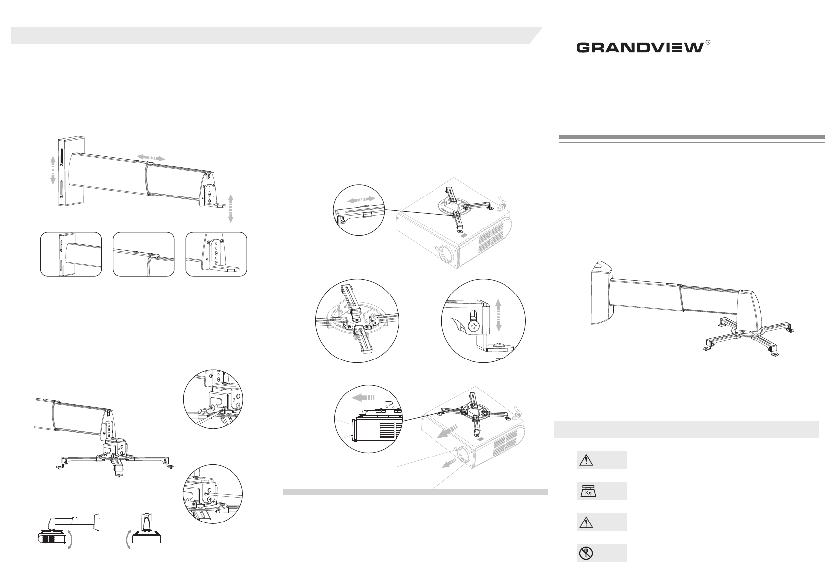
Height and length adjustment
1.Loos en t he p osi tioning scre ws o f lo w bo ard (2-2), the heigh t of GPC P
Main Bar Overview can be adjusted (the maxi mum heigh t: 45mm) as
figure 1 1.
2.Loos en the pos iti oning scr ews of main bar (1-4 ), the len gth of
subsidiar y bar (1-3 ) can be ad justed (c heck abou t the data of scope f or
instal lat ion) as f igu re 12.
3.Loos en the pos itioning screws of in stallati on board (1-5) , the height
of in sta llation board (1-5) c an be adjusted ( the max imum he ight: 3 0mm)
as figur e 13.
figur e 11 figur e 12 figur e 13
Angle Ad justmen t
1.Loos en the p ositioni ng screws (front a nd back) for adjustin g the
angle, and then rotate the scre wdriv er for fine turn ing to the required
angle as f igu re 14.
2.Loos en the p osi tioning screws ( left and right) for adjustin g the angle,
and then rotate the screwdri ver for f ine turning to the required angle as
figure 1 5.
Installation of main bar
1.Firs tly , plea se con firm how many install ati on hol es the proje cto r has?
3 or 4.
2.If th ere are 3 h oles, the insta lla tion a rms (4-3) need to be taken apart
from I nstallat ion bracket fir stly. Connec t 3 i nst allation arms(4-3) t o the
projec tor , and the n conne ct the in sta llati on arms ( 4-3 ) to the install ati on
base (4- 6) However ,the insta llation ba se needs to be t he center of
projec tor . Figure 16
3.Conn ect th e instal lat ion arms to the proj ector conve rsely if the
dis tance of i nstalla tion hole s is less tha n 1 20mm. Con nect the
instal lation arms (4-3) to th e inst allat ion bas e (4-6 ) via sliding
instal lat ion button ( 4-5) as figu re 17
4.Rota te th e adjus tab le screw (4- 4) for adjus ting the hei ght of instl lation
arms (4- 2) if the inst all ation hole s are not at the s ame level as f igure 18.
5.The front or b ack o f adjuster must be p ara llel to th e surface of
projec tor a s figure 19.
figur e 16
Scope o f
adjus tment :10mm
figur e 17 figur e 18
GRANDVIEW REPRODUCING GENUINE COLORS
Instruction Manual
Projector Wall Mount
Applicable Model
GPCP-D4060
GPCP-D6090
GPCP-D90150
Please read before using
Thank you for purchasing our prod ucts. Please read the instructio n
manual caref ully in order to ensure this pro jector lift is s uitable for your
projection equipment .
The angle of
vertical tilt:±15°
The nagle of
horizontal tilt:±5°
figur e 14
figur e 15
The front or back of
adjuster must be
parallel to the surface
of projector
Grandview Crystal
Screen Canada Ltd.
#11- 3751 N orth F rase r Way,
Marin e Way Bus ines s Cent re,
Burna by, BC, Ca nada V 5J 5G4
Tel: 1-604- 412- 9777
Fax: 1- 604- 412- 9796
Websi te: ww w.gran dvie wscr een. ca
figur e 19
Guangzhou Grandview
Crystal Screen Co., Ltd.
P.O. 511400 Fede ral In d. Zon e No. 36 3,
Yushan Wes t Road ,Shi qiao , Pany u
Distr ict, G uang zhou , Guan gdon g, Chi na
Tel: +8620- 8489 -949 9
Fax: +8 620- 8480 -334 3
Websi te: ww w.gran dvie wscr een. com
Cautious
Warnings
Weight
Caution
Do not
take apart
For safet y, t he m inim um of ceil ing must be 20Kgweight
The maxim um w eigh t of ins tall atio n br acke t is 20Kg
(note: the insta llation br acket's ma ximum weig ht of GPCP -D90150 is 15kg)
Pleas e do not incline t he p roje ctor the ext reme ly.
Please do not take apart the accessories of projector
ceiling mount.
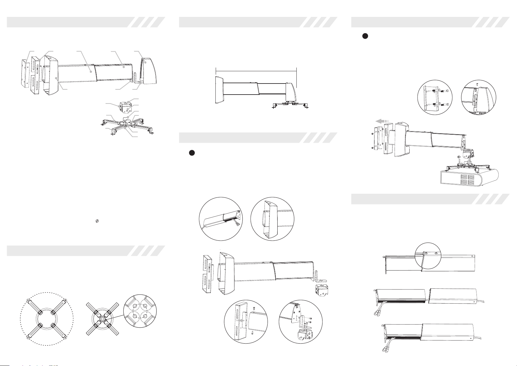
Parts
Scope
Steps of installation
GPCP-D is combined by GPCP and GPD
2-3
2-1
GPCP Main Bar Overview
1-1 Top Cap
1-2 Front Board
1-3 Subsidiary Bar
1-4 Main Bar
1-5 Installation Board
2-1 Low Cap
2-2 Low Board
2-3 Fixation
GPD Adjustment Overview
3-1 Adjuster
3-2 Hanging Button
3-3 Horizontal Adjusting Hole
4-1 Installation Bracket
4-2 Vertical Adjusting Button
4-3 Installation Arm
4-4 Adjustable Screw
4-5 Sliding Installation
Button
4-6 Installation Base
1-11-31-42-2
1-2
1-5
3-3
4-3
4-4
Accessories
①M3X8 Philips Screw (4pcs)
②M4X8 Philips Screw (4pcs)
③M5X8 Philips Screw (4pcs)
④M5X8 Philips Screw (2pcs)
⑤M6X12 Anti-Slip Screw (2pcs)
⑥M5X10 Philips Screw (5pcs)
⑦M6X25 Tapping Screw (4sets)
⑧ 6X50 Wood Screwn (4sets)
3-1
3-2
4-1
4-2
4-6
4-5
Scope f or ins tall ation (H is the distance between ceiling and projector)
The H of GPCP-D 4060 is 420m m~60 0mm
The H of GPCP-D 6090 is 600mm~900mm
The H of GPCP-D 90150 is 900 mm~1 500m m
H
GPCP-D
Steps of installation
1
Firstly, collect the power wires to the main bar as figure 1.
Invaginate the low cap to the main bar as figure 2. Install the
low board to the main bar, and then fasten the screws
(accessories 5) as figure 3. Finally, install the front board to
installation board of main bar and install the adjuster to the
front board, and then fasten the screws (accessories 6) as
figure 4.
2
Install the fixation on the wall (choose the screws according
to the materials of wall, Use the screw of accessory 7 for
concrete-wall, and use the screw of acessory 8 for woodwall) as figure 5.And then, install the Main Bar Overview to
the fixation and fasten the screws (accessory 4)as figure 5.
Finally, connect the GPD Adjusting Overview to the adjuster
and then fasten the screws (accessory 6 ) as figure 7.
figur e 5 figur e 7
figur e 6
Details of installation
Wires collection
Loosen out t he p ositioni ng scre ws o f main bar (1-4) as f igu re 8 , an d then
take apa rt subsidia ry bar (1- 3) from main bar ( 1-4). Pu t the wir es into
the main bar (1-4) then in sert the wi res to the pla stic groove of
subsidiar y bar (1- 3). A nd then , re- insta ll th e subsidia ry bar (1 -3) t o main
bar (1-4 ) after coll ect ing the w ire s as figure 9- 10.
Scope
Scope f or ins tall ation (Installation hole of projector):
Maxim um sco pe for i nsta llation:360mm diameter
Minim um sco pe for i nsta llation:50mm diameter
Note: C onnec t the installa tion arms to the p rojector con versely for di fferent inst allat ion
holes o f proje ctor.
Maxim um diameter : 360mm
Minim um diameter : 50mm
figur e 1 figur e 2
figur e 3 figur e 4
figur e 8
figur e 9
figur e 10
 Loading...