

Graff ME25 6111 Series Installation Instructions Manual

TWO HANDLE WIDESPREAD LAVATORY FAUCET
GRIFO DE DOS MANILLAS DE EXTENSIÓN
This faucet complies with NSF61/9, ASME/ANSI A112.18.1
and CSA B 125 Standards.
Este grifo se encuentra conforme con losestandares de NSF61/9,
de ASME/ANSI A112.18.1 y de CSA B 125.
Dear Customer Estimado Cliente
ENGLISH
Thank you for selecting our product. We are confident we can fully satisfy Muchas gracias por elegir nuestro producto. Estamos seguros que podemos
your expectations by offering you a wide range of technologically advanced satisfacer completamente sus expectativas ofreciéndole una amplia variedad
products which directly result from our many years of experience in faucet
and fitting production.
Installation Instructions Instrucciones de Instalación
~
ESPANOL
de productos tecnológicamente avanzados que resultan directamente de
muchos años de experiencia en grifos y su producción apropiada.
ATTENTION!
LM41B
For care, use soft towel with soap and water only! Under no
circumstances should you use any chemicals.
C17B
2-1/2"
Ø2"
(64mm)
( 50mm)Ø
1/4"
(6.5mm)
ØØ2"
( 50mm)
(30mm)
1-3/16"
1-13/16" (46.5mm)
ATENCIÓN!
Ø
13/16"
( 20mm)
Ø
Para el cuidado, utilice solamente una toalla suave con jabón
y aqua! Bajo ninguna circunstancia no use productos químicos.
6-5/16" (160mm)
(34mm)
1-5/16"
ØØ2"
( 50mm)
1/2"
Ø
Ø
( 13mm)
Model
ME25 6111-***
Modelo
~ 8-15/16" (~ 227mm)
(~ 130mm)
~ 5-1/8"
5/16"
Ø
Ø
( 8mm)
ENGLISH
For easy installation of your
GRAFF faucet you will need:
to READ ALL the instructions
completely before beginning,
to READ ALL the warnings, care and
maintenance information.
To complete the project, you
should:
gather the tools and all the parts
you will need,
prepare the mounting area,
mount the faucet,
connect the supply lines,
finally test and flush the faucet.
You should have the following
tools:
adjustable wrench,
adjustable pliers,
hex key (included in the box),
®
Teflon tape.
~
Para la instalación fácil de su grifo
de la GRAFF usted necesitará:
LEER TODAS las instrucciones
completamente antes de comenzar,
LEER TODA la información sobre las
advertencias, cuidado y
mantenimiento.
Para terminar el proyecto, usted
debe:
recolectar las herramientas y todas
las piezas que usted necesitará,
prepare el área para el montaje,
monte el grifo,
conecte las líneas de fuente,
finalmente pruebe y limpie el grifo
con un chorro de agua.
Usted debe tener las herramientas
siguientes:
llave ajustable,
alicates acanalados,
llave hexagonal (incluido en la caja),
cinta adhesiva de Teflon .
ESPANOL
®
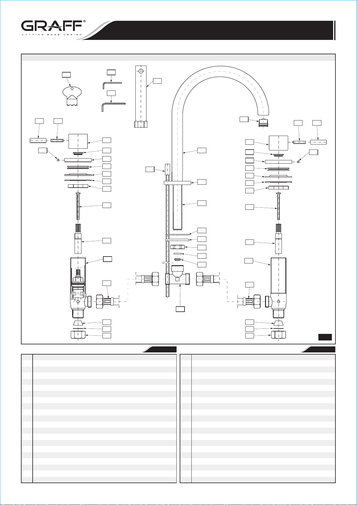
SET-UP DIAGRAM DIAGRAMA DE INSTALACIÓN
SIZE AND SPACING OF ASSEMBLY OPENINGS
TAMAÑOS Y DISTRIBUCIÓN DE LOS ORIFICIOS DE MONTAJE
Ø1-3/16"
( 30mm)Ø
1/4"
(6mm)
~ 8" (~ 204mm)
MAX. 2"
(MAX. 50mm)
Hot water valve is marked
with red sticker
La válvula de agua caliente
está marcada con
le etiqueta roja
Supply tube - 3/8" O.D. (9.5mm)
Entrada de agua caliente
tuberia - 3/8" O.D. (9.5mm)
Ø1-3/16"
( 30mm)Ø
Ø1-3/16"
( 30mm)Ø
~ 8" (~ 204mm)
Cold water valve is
marked with blue sticker
La válvula de agua fría
está marcada con
le etiqueta azul
Supply tube - 3/8" O.D. (9.5mm)
Entrada de agua fría
tuberia - 3/8" O.D. (9.5mm)
IOG 2818.00
1
Rev. 3 May 2017
TWO HANDLE WIDESPREAD LAVATORY FAUCET
This faucet complies with NSF61/9, ASME/ANSI A112.18.1
and CSA B 125 Standards.
Este grifo se encuentra conforme con losestandares de NSF61/9,
de ASME/ANSI A112.18.1 y de CSA B 125.
ME25 6111-LM41B
GRIFO DE DOS MANILLAS DE EXTENSIÓN
Installation Instructions Instrucciones de Instalación
25
21
24
K3
23
22
20
19
18
17
16
15
14
13L
K1
K2
K4
2
23
1
5
3
4
6
7
8
9
10
22
20
19
18
17
16
15
14
13R
24
25
21
12
26
27
28
SPOUT
1
AERATOR
2
SPOUT BASE
3
THREADED STUB PIPE
4
DRAIN LIFT-ROD
5
RUBBER WASHER
6
METAL WASHER
7
MOUNTING NUT
8
O-RING SEAL
9
NOZZLE
10
T-CONNECTION
11
HOSE, 13-3/4” (350mm) LENGTH (2 PCS.)
12
VALVE WITH A 1/4 TURN CERAMIC HEAD /clockwise opening/
13R
VALVE WITH A 1/4 TURN CERAMIC HEAD /counterclockwise
13L
opening/
HEAD SPINDLE ELONGATION (2 PCS.)
14
SCREW (2 PCS.)
15
NUT (2 PCS.)
16
METAL WASHER (2 PCS.)
17
RUBBER WASHER (2 PCS.)
18
VALVE FLANGE (2 PCS.)
19
IOG 2818.00
ENGLISH
12
11
26
27
28
CAÑO
1
AEREADOR
2
BASE DEL CAÑO
3
TUBO ROSCADO
4
VARILLA ELEVADORA DE DESAGÜE
5
ARANDELA DE CAUCHO
6
ARANDELA DE METAL
7
TUERCA DE MONTAJE
8
JUNTA TÓRICA
9
TOBERA
10
TUBO EN “T”
11
MANGUERA LONGITUD DE 13-3/4” (350mm) (2 PIEZAS)
12
VÁLVULA (con la cabeza ceramica) 1/4 GIRO /abre hacia la derecha/
13R
VÁLVULA (con la cabeza ceramica) 1/4 GIRO /abre hacia la
13L
izquierda/
EXTENSIÓN DEL HUSO DE LA CABEZA (2 PIEZAS)
14
TORNILLO (2 PIEZAS)
15
TUERCA (2 PIEZAS)
16
ARANDELA DE METAL (2 PIEZAS)
17
ARANDELA DE GOMA (2 PIEZAS)
18
BRIDA DE LA VÁLVULA (2 PIEZAS)
19
2
1
~
ESPANOL
Rev. 3 May 2017
 Loading...