

Graff C14B-WS Series, C14-VS Series Installation Instructions Manual
HANDLES ASSEMBLY
ENSAMBLE DE LOS MANILLAS
Installation Instructions Instrucciones de Instalación
Dear Customer Estimado Cliente
ENGLISH
~
ESPANOL
Thank you for selecting our product. We are confident we can fully satisfy Muchas gracias por elegir nuestro producto. Estamos seguros que podemos
your expectations by offering you a wide range of technologically advanced
products which directly result from our many years of experience in faucet
and fitting production.
ATTENTION!
For easy installation of your
GRAFF product you will need:
You should have the following tools:
Para la instalación fácil de su producto
de la GRAFF usted necesitará:
Usted debe tener las herramientas siguientes:
For care, use soft towel with soap and water only! Under no
circumstances should you use any chemicals.
ENGLISH
to READ ALL the instructions completely before
beginning,
to READ ALL the warnings, care and maintenance
information.
adjustable wrench,
channel pliers,
®
Teflon tape,
plumbers putty or caulking (silicone).
ESPANOL
LEER TODAS las instrucciones completamente antes de
comenzar,
LEER TODA la información sobre las advertencias,
cuidado y mantenimiento.
llave ajustable,
alicates acanalados,
cinta adhesiva de Teflon ,
masilla o silicona.
®
~
satisfacer completamente sus expectativas ofreciéndole una amplia variedad
de productos tecnológicamente avanzados que resultan directamente de
muchos años de experiencia en grifos y su producción apropiada.
ATENCIÓN!
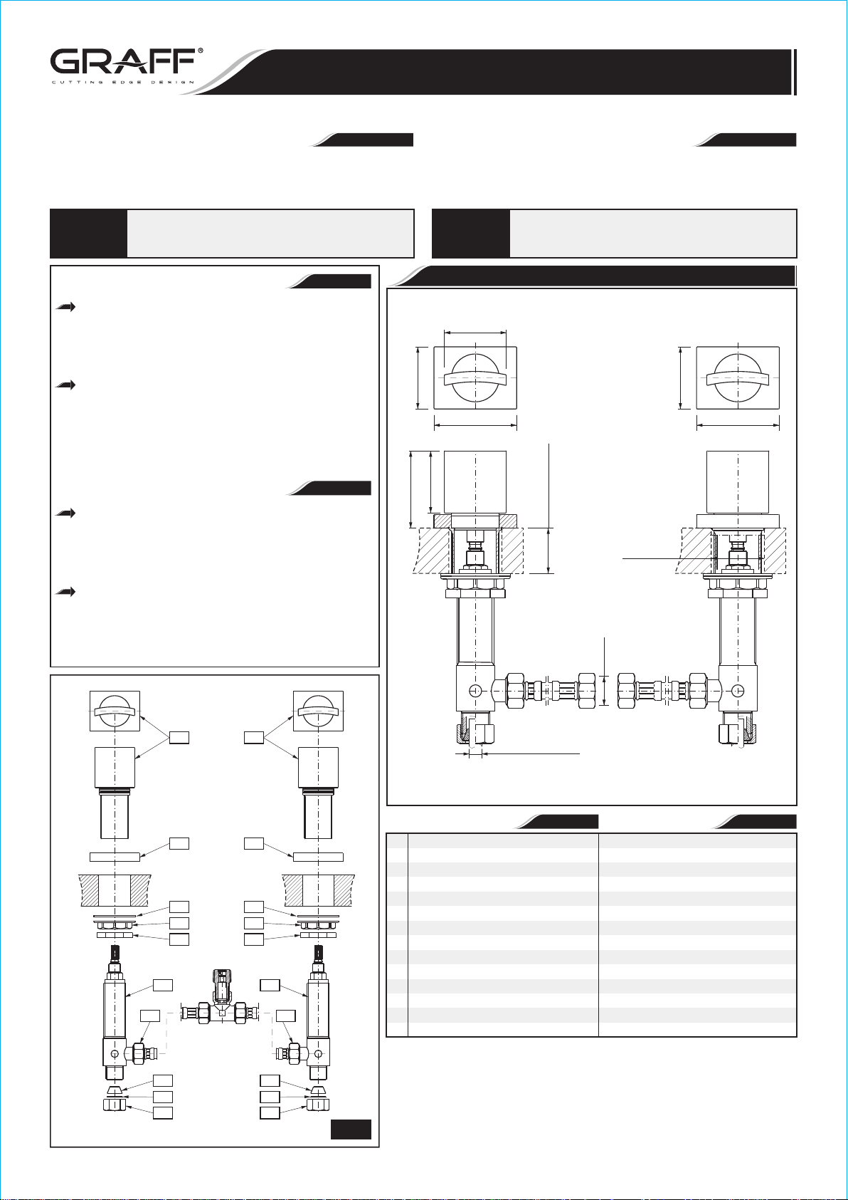
HANDLES ASSEMBLY • ENSAMBLE DE LOS MANILLAS
1-7/8"
(48mm)
1-7/8"
(48mm)
2-1/2"
(64mm)
1-7/8"
(48mm)
2-3/8" (60mm)
Para el cuidado, utilice solamente una toalla suave con jabón
y aqua! Bajo ninguna circunstancia no use productos químicos.
Model
C14B-WS-**
Modelo
1-7/8"
(48mm)
2-1/2"
(64mm)
(MAX. 38mm)
MAX. 1-1/2"
Ø1-1/2"
(Ø38mm)
G1/2"
1 1
2 2
3 3
4 4
5 5
6L
6R
10 10
7 7
8 8
9 9
Ø3/8" (Ø9.5mm)
* – type of finish
* – tipo de acabado
~
ESPANOL
1
HANDLE ASEMBLY (2 PCS.)
2
HANDLE BASE (2 PCS.)
3
WASHER (2 PCS.)
4
FLANGED NUT (2 PCS.)
5
COUNTER NUT (2 PCS.)
6R
RIGHT VALVE (with clockwise
opening cartridge)
6L
LEFT VALVE (with counterclockwise
opening cartridge)
7
CONE GASKET (2 PCS.)
8
WASHER (2 PCS.)
9
COUPLING NUT (2 PCS.)
10
HOSE 13-3/4” (350mm) length,
(2 PCS.)
ENGLISH
JUEGO DE MANILLA (2 PIEZAS)
BASE DE LA MANILLA (2 PIEZAS)
ARANDELA (2 PIEZAS)
TUERCA CON BRIDA (2 PIEZAS)
TUERCA DE CONTRA (2 PIEZAS)
VÁLVULA DERECHA (con cartucho
que se abre hacia la derecha)
VÁLVULA IZQUIERDA (con cartucho
que se abre hacia la izquierda)
JUNTA CÓNICA (2 PIEZAS)
ARANDELA (2 PIEZAS)
TUERCA DE FIJACIÓN (2 PIEZAS)
MANGUERA, longitud 13-3/4”
(350mm), (2 PIEZAS)
1
IOG 2800.80
1
Rev. 2 April 2015
1-7/8"
(48mm)
Installation Instructions Instrucciones de Instalación
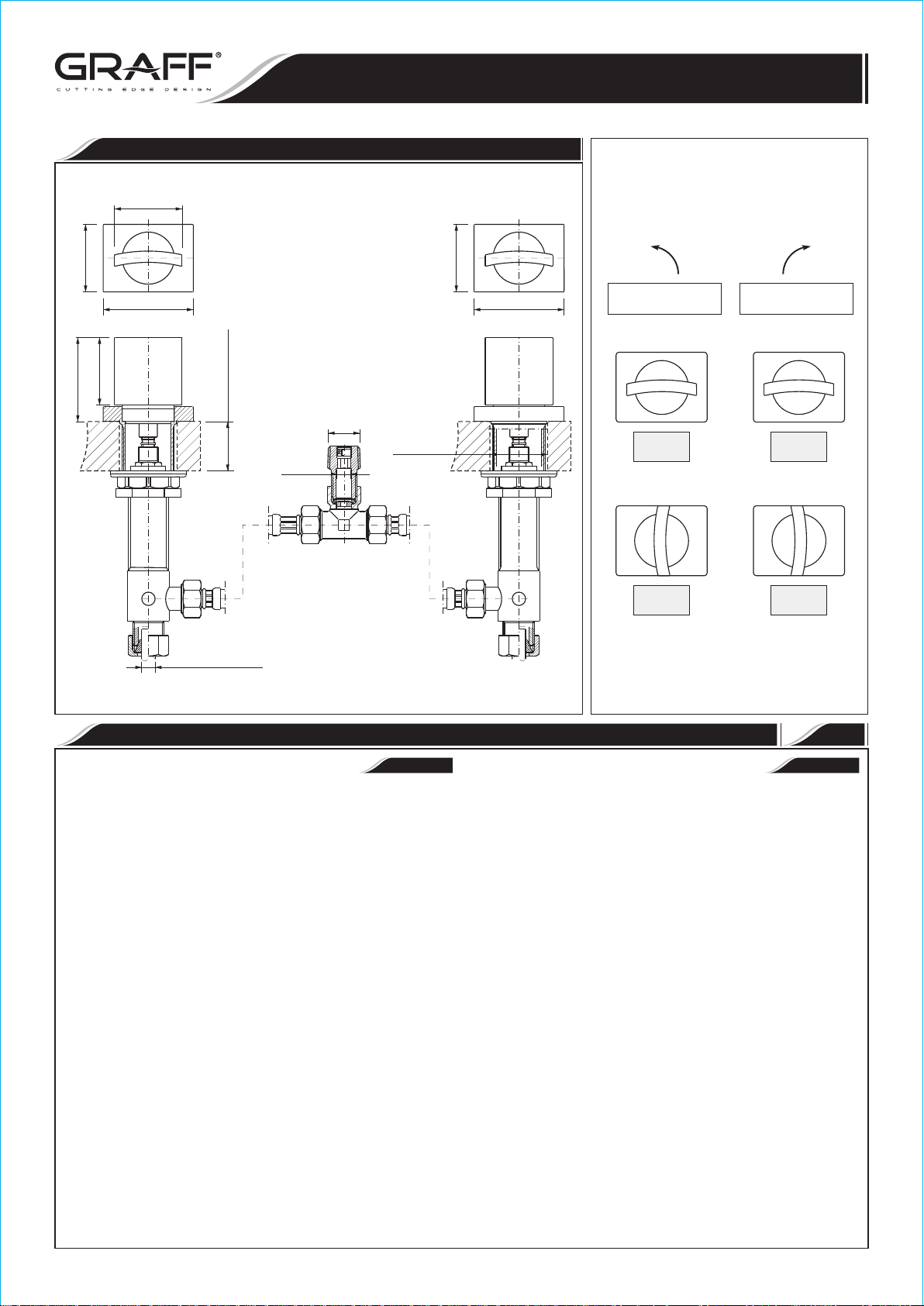
Model
C14-VS-**
Modelo
HANDLES ASSEMBLY • ENSAMBLE DE LOS MANILLAS
HANDLES ASSEMBLY
ENSAMBLE DE LOS MANILLAS
1-7/8"
(48mm)
1-7/8"
2-3/8" (60mm)
2-1/2"
(64mm)
(48mm)
MAX. 1-1/2"
Ø3/8" (Ø9.5mm)
* – type of finish
* – tipo de acabado
(MAX. 38mm)
5/16"
1/2NPT
Ø1-1/2"
(Ø38mm)
1-7/8"
(48mm)
2-1/2"
(64mm)
¼ turn
¼ de vuelta
Counterclockwise opening
Se abre hacia la izquierda
Off
Cerrado
On
Abierto
¼ turn
¼ de vuelta
Clockwise opening
Se abre hacia la derecha
Off
Cerrado
On
Abierto
HANDLES INSTALLATION INSTALLACIÓN DE LAS MANILLAS
See fig. 2.1-2.2, 3.1-3.4
1) Place handle base (2) and center over side hole of mounting surface -
see fig. 1 and 3.1.
2) Insert handle assembly (1) into the hole of a handle base (2) and a
deck. From underneath the lavatory place the washer (3) and then
screw the flanged nut (4) (fig.3.1).
3) Set the handle as on fig. 1 - “OFF” position.
4) Turn the spline of a cartridge in a valve (6R) & (6L) to OFF
position:
• in the hot water valve (fig. 2.1): left valve marked with the red
sticker turn the cartridge spline (A) in clockwise direction,
• in the cold water valve (fig. 2.2): right valve marked with the blue
sticker turn the cartridge spline (B) in counterclockwise direction.
5) Turn onto the valve (6R) & (6L) counter nut (10) (fig. 3.2).
6) Holding the valve with the outlet pointing towards you (in case of hot
water valve) (6L) / or outwards (in case of cold water valve (6R))
put the valve into the handle assembly (1), so the spline of the
cartridge mates with the spline of the handle (fig. 3.2).
7) Thread in the valve home, then release the valve 0.5 to 1.5 turn.
Position the handle (1) as on fig. 1. Tighten lightly the counter nut
(5) on the valve (fig. 3.3).
8) Note the position of the outlet of the valve and make sure it fits the
flexible hose connection (10). If it is ok tighten the
(5) - see fig. 3.4, if not move the valve by the required
To achieve this do the following:
• unscrew the valve without disconnecting the handle,
• hold the handle,
• disconnect the valve from the handle,
• rotate the valve by required angle,
• connect the valve to the handle as described above,
• secure the handle and the valve with the counter nut (5).
ENGLISH
counter nut
angle.
1
~
Ver dis. 2.1-2.2, 3.1-3.4
1) Coloque la base de la manilla (2) y centre en el agujero lateral de la
superficie de montaje - ver dis. 1 y 3.1.
2) Poner el juego de manilla (1) al agujero de la base de la manilla (2) y
de la superficie de montaje. Colocar la arandela por debajo del lavabo
(3) y atornillar la tuerca con brida (4) (dis. 3.1).
3) Poner la manilla como en el dib. 1 en la posición “OFF”.
4) Poner la polichaveta del cartucho en la válvula (6R) y (6L) en la
posición “cartucho cerrado” - “OFF”:
• en el caso de la válvula de agua caliente (dis. 2.1): la válvula
izquierda con etiqueta roja con cartucho cerrado a la derecha girar la polichaveta del cartucho (A) a la derecha,
• en el caso de la válvula de agua fría (dis. 2.2) válvula derecha con
etiqueta azul con cartucho cerrado a la izquierda - girar la
polichaveta del cartucho (B) a la izquierda.
5) Atornillar en la válvula (6R) y (6L) la tuerca de contra (10) (dis.
3.2).
6) Teniendo la válvula con su salida hacia sí (en el caso de la válvula de
agua caliente, (6L) / hacia fuera (en el caso de la válvula de agua fría
(6R) ), ponerla a la manilla (1), la polichaveta del cartucho se
engranará con la polichaveta de la manilla (dis. 3.2).
7) Enroscar la válvula a su máximo y después retirar la válvula a 0.5
hacia 1.5 de la rotación. Poner la manilla (1) como en el dib. 1.
Apretar ligeramente la tuerca de contra (5) en la válvula (dis. 3.3).
8) Recordar la posición del escape de la válvula y estimar si concuerda
con la manguera flexible (10). Si concuerda, atornillar
de contra (5) - ver el dis. 3.4., si no concuerda; reponer la
válvula teniendo en cuenta el ángulo adecuado. Para hacer eso:
• destornillar la válvula sin desconectarla con la manilla,
• sujetar la manilla,
• desconectar la válvula de la manilla,
• reponer la válvula hacia su ángulo adecuado,
• conectar la válvula con la manilla teniendo en cuenta lo susodicho,
• proteger la manilla y la válvula con la tuerca de contra (5).
ESPANOL
la tuerca
IOG 2800.80
2
Rev. 2 April 2015
 Loading...