

IOG 2328.50
Rev. 1 December 2007
ENGLISH
~
ESPANOL
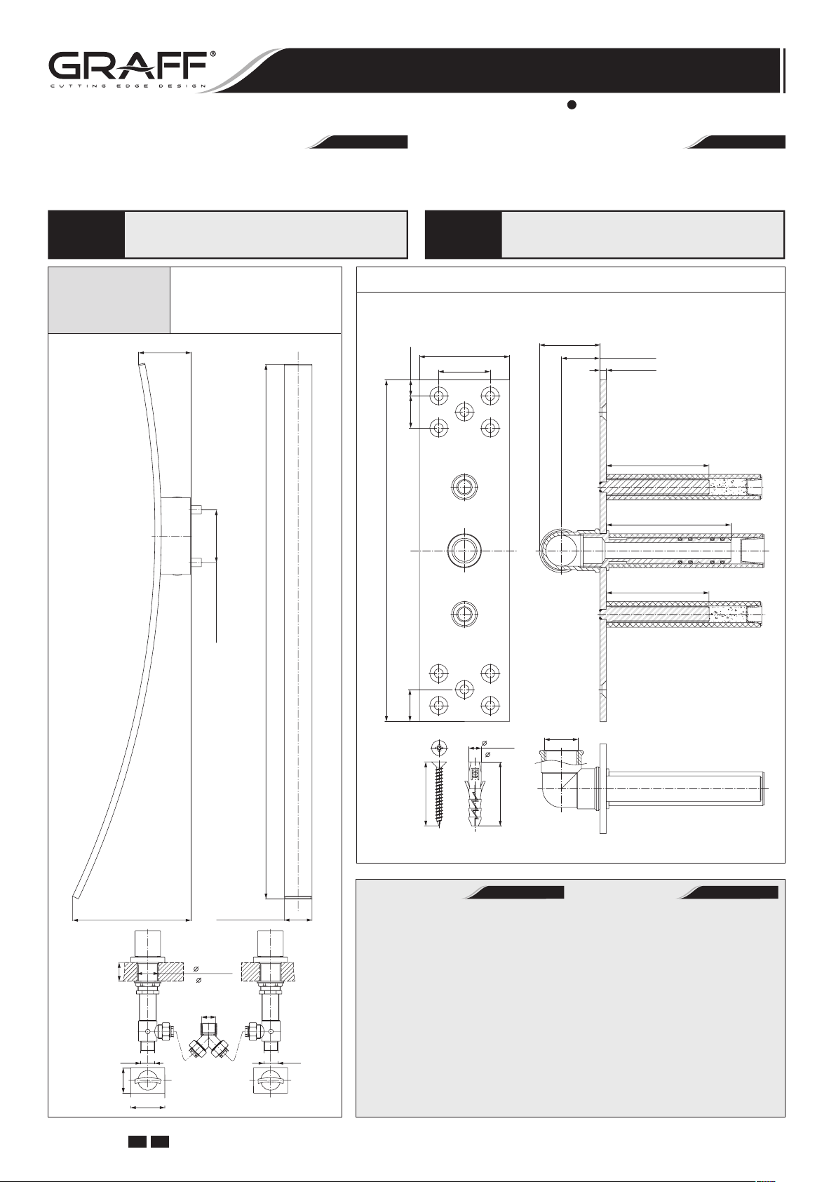
BATH MIXER (with Wall-Mount Spout)
EL GRIFO DEL BAÑO (con Caño Montado en la Pared)
Installation Instructions Instrucciones de instalación
Dear Customer Estimado Cliente
Thank you for selecting our product. We are confident we can fully satisfy
your expectations by offering you a wide range of technologically advanced
products which directly result from our many years of experience in mixer
and fitting production.
For care, use soft towel with soap and water
ATTENTION! ATENCIÓN!
LUNA
only! Under no circumstances should you use
any chemicals.
Bath Mixer
with Wall-Mount Spout
El Grifo del Baño
con caño Montado
en la Pared
~3-29/32" (~ 99mm)
Muchas gracias por elegir nuestro producto. Estamos seguros que podemos
atisfacer completamente sus expectativas ofreciéndole una amplia variedad
de productos tecnológicamente avanzados que resultan directamente de
muchos años de experiencia en grifos y su producción apropiada.
Para el cuidado, utilice solamente una toalla
suave con jabón y aqua! Bajo ninguna
circunstancia no use productos químicos.
Spout Connection Rough Set • Conjunto de Conexión del Caño
~1-55/64" (~47mm)
31/64"
(12.5mm)
63/64"
(25mm)
2-3/4" (70mm)
1-37/64" (40mm)
1-3/16" (30mm)
3/16" (5mm)
3-5/32" (80mm)
3-53/64" (97mm)
~8-25/32" (~ 223mm)
(38mm)
MAX. 1-1/2"
G3/4"
(48mm)
1-57/64"
2-33/64" (64mm)
~3-29/32" (~ 99mm)
~2-3/64" (~ 52mm)
2x 1-5/8"
(2x 41.5mm)
G3/4"
~39-9/16" (~ 1005mm)
G3/4"
10-15/32" (266mm)
63/64"
(25mm)
( 10mm)
1-31/32" (50mm)
Tools and Materials
Tape Measure
•
Pencil
•
Drill
•
Blade Screwdriver
•
Philips Screwdriver
•
Hex Wrenches
•
Level
•
Silicone Sealant
•
25/64"
1-31/32" (50mm)
3-5/32" (80mm)
G3/4"
Herramientas y materiales
Cinta para media
•
Lápiz
•
Taladro
•
Destornillador plano
•
Destornillador de punta
•
de cruz o Phillips
Llave hexagonales
•
Nivel
•
Sellador de silicona
•
ESPAÑOLENGLISH
GB E
GB E
1
BATH MIXER (with Wall-Mount Spout)
EL GRIFO DEL BAÑO (con Caño Montado en la Pared)
Installation Instructions Instrucciones de instalación
LUNA
2
5
Make sure that the
Teflon® insert is in
a proper position
in the spout holder.
Asegúrese que el
insertador de Teflon
se encuentren en
su lugar en el parte
de montaje del caño.
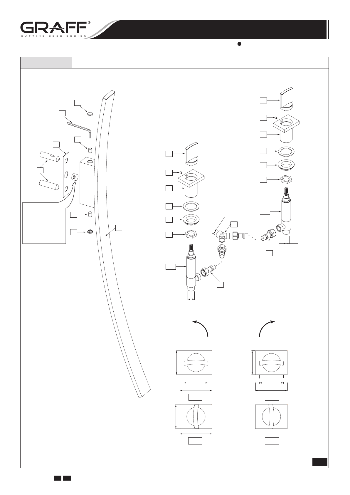
Bath Mixer • El Grifo del Baño
4
A
3
3
®
4
1
10
11
6
8
7
6
9
10
8
11
7
9
G3/4"
12A
14
3/4"
12B
13
3/4"
1/4 TURN
1/4 DE VUELTA
COUNTERCLOCKWISE OPENING
SE ABRE HACIA LA IZQUIERDA
1-57/64" (48mm)
1-57/64" (48mm) 1-57/64" (48mm)
2-33/64" (64mm)
OFF OFF
13
1/4 TURN
1/4 DE VUELTA
CLOCKWISE OPENING
SE ABRE HACIA LA DERECHA
1-57/64" (48mm)
2-33/64" (64mm)
IOG 2328.50
GB E
1-57/64" (48mm)
2-33/64" (64mm)
ON ON
2
1.1
Rev. 1 December 2007
BATH MIXER (with Wall-Mount Spout)
EL GRIFO DEL BAÑO (con Caño Montado en la Pared)
Installation Instructions Instrucciones de instalación
1 WALL-MOUNT SPOUT CAÑO MONTADO EN LA PARED
2 WASHER ARANDELA
3 FIXING SCREW (2 PCS.) TORNILLO DE FIJACIÓN (2 PIEZAS)
4 CAP (2 PCS.) TAPÓN (2 PIEZAS)
5 MOUNTING SLEEVE (2 PCS.) CASQUILLO DE MONTAJE (2 PIEZAS)
6 HANDLE ASSEMBLY (2 PCS.) JUEGO DE LA MANILLA (2 PIEZAS)
7 HANDLE BASE (2 PCS.) BASE DE LA MANILLA (2 PIEZAS)
8 SCREW TORNILLO
9 WASHER (2 PCS.) ARANDELA (2 PIEZAS)
10 FLANGED NUT (2 PCS.) TUERCA CON BRIDA (2 PIEZAS)
11 COUNTER NUT (2 PCS.) TUERCA DE CONTRA (2 PIEZAS)
12A RIGHT VALVE (with clockwise opening cartridge) VÁLVULA DERECHA (con cartucho que se abre hacia la derecha)
12B LEFT VALVE (with counterclockwise opening cartridge) VÁLVULA IZQUIERDA (con cartucho que se abre hacia la izquierda)
HOSE G3/4”-G3/4”
13
11-13/16” (300mm) length, (2 PCS.)
14 T-CONNECTION CONEXIÓN „T”
A HEX KEY LLAVE HEXAGONAL
MANGUERA G3/4”-G3/4”
longitud 11-13/16” (300mm), (2 PIEZAS)
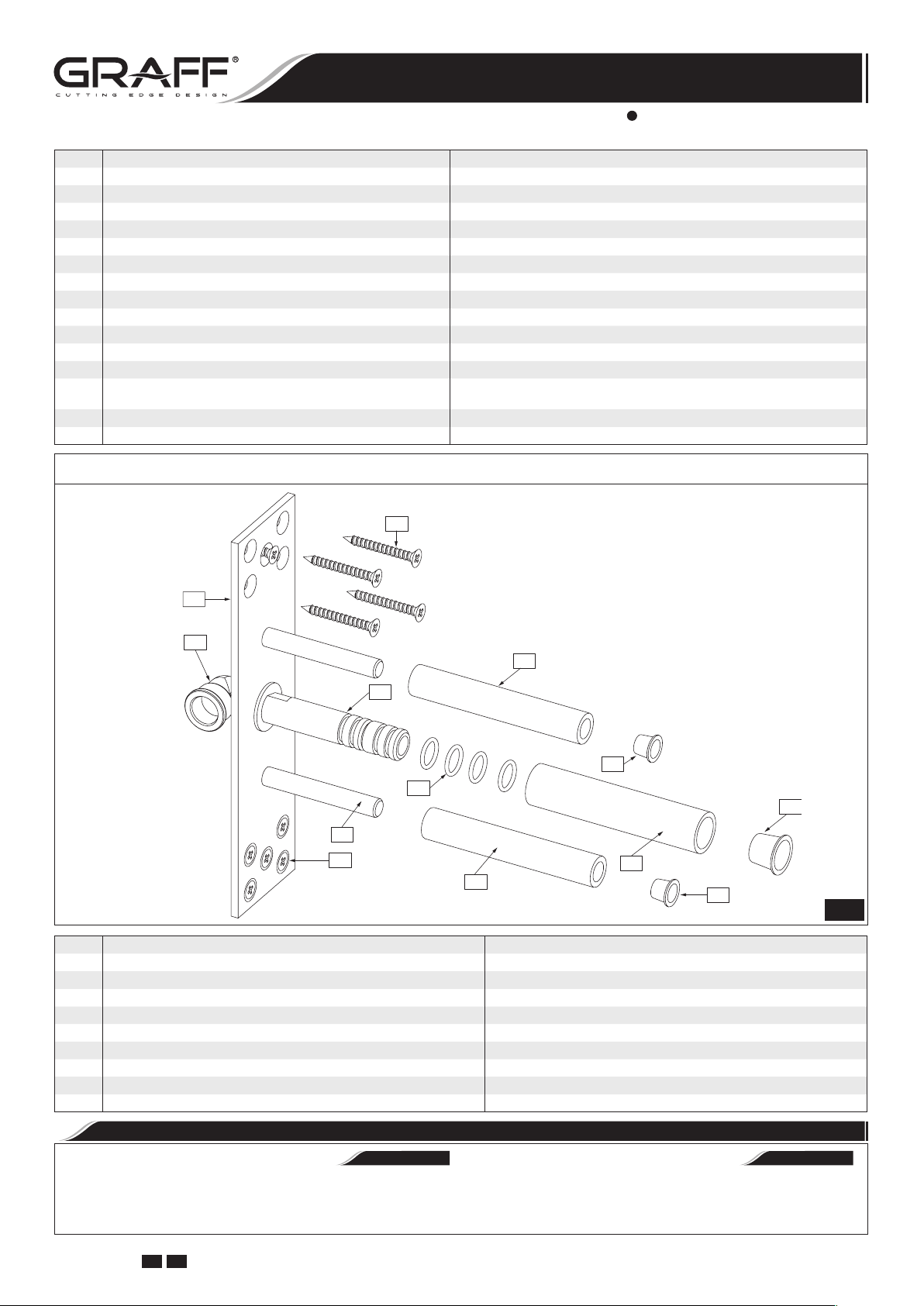
Spout Connection Rough Set • Conjunto de conexión del caño
R9
R
R1
R7
R2
R8
R4
R6
R3
R9
R5
R7
R8
R COMPLETE SPOUT CONNECTION ROUGH CONJUNTO COMPLETO DE CONEXIÓN DEL CAÑO
R1 SUPPLY ELBOW G3/4” CODO G3/4” DE SUMINISTRO
R2 SPOUT CONNECTION CONEXIÓN DEL CAŃO
R3 MOUNTING PIN (2 PCS.) PERNO DE MONTAJE (2 PIEZAS)
R4 O-RING SEAL (4 PCS.) JUNTA O-RING (4 PIEZAS)
R5 SPOUT CONNECTION PROTECTION CONECTOR DEL CAŃO DE PROTECCIÓN
R6 PROTECTION CAP TAPÓN DE PROTECCIÓN
R7 PROTECTION SLEEVE (2 PCS.) CASQUILLO DE PROTECCIÓN (2 PIEZAS)
R8 PROTECTION CAP (2 PCS.) TAPÓN DE PROTECCIÓN (2 PIEZAS)
R9 SCREW WITH ANCHOR (10 PCS) TORNILLO CON ESTACA (10 PIEZAS)
1.2
Carefully unpack and inspect all the components for damage. To protect against damage, return all components
to the carton until ready to install.
IOG 2328.50
GB E
PRODUCT INSPECTION
Desembale con cuidado y cerciórese de que ningún com
ponente esté dañado. Para protección contra daños, vuelva
a colocar todos los componentes en la caja de embalaje hasta
el momento de su instalación.
3
INSPECCIÓN DEL PRODUCTO
•
ESPAÑOLENGLISH
Rev. 1 December 2007
-
BATH MIXER (with Wall-Mount Spout)
EL GRIFO DEL BAÑO (con Caño Montado en la Pared)
Installation Instructions Instrucciones de instalación
LUNA
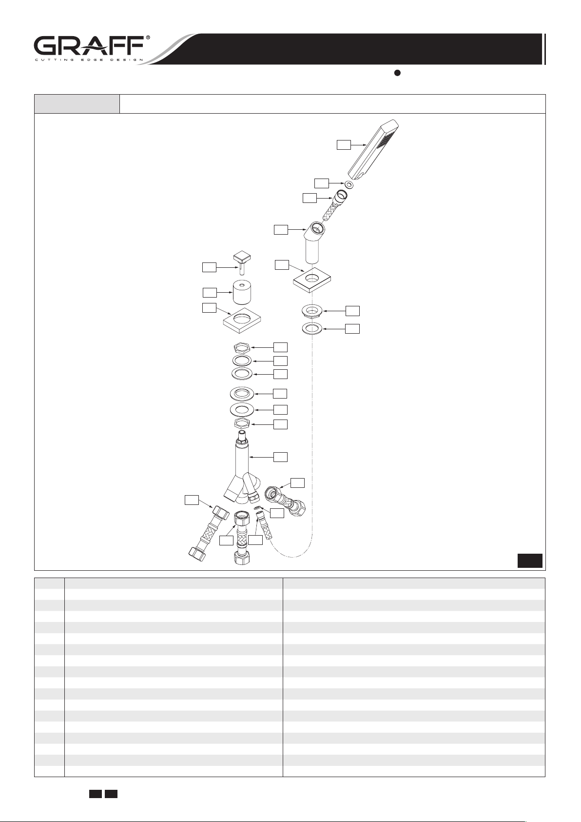
Diverter Valve & Shower Handset • Válvula de Desviador y de la Teleducha
15
16
17
18
23
24
25
19
20
21
26
27
28
29
30
26
31
32
32
22
17
32
15 SHOWER HANDSET TELEDUCHA
16 FLAT SEAL EMPAQUETADURA PLANA
17 SHOWER HOSE 59” (1500mm) length MANGUERA DE DUCHA de la longitud 59” (1500mm)
18 SHOWER HANDSET SOCKET ASIENTO DE TELEDUCHA
19 BASE BASE
20 RUBBER PAD ARANDELA DE CAUCHO
21 FLANGED NUT TUERCA CON BRIDA
22 FLAT SEAL EMPAQUETADURA PLANA
23 DIVERTER SWITCH KNOB BOLA DEL DESVIADOR
24 VALVE COVER CUBIERTA DE LA VÁLVULA
25 BASE OF VALVE COVER BASE DE LA CUBIERTA DE LA VÁLVULA
26 NUT (2 PCS.) TUERCA (2 PIEZAS)
27 METAL WASHER ARANDELA DE METAL
28 WASHER ARANDELA
29 WASHER ARANDELA
30 METAL WASHER ARANDELA DE METAL
31 DIVERTER VALVE VÁLVULA DE DESVIADOR
HOSE G3/4”-G3/4” 23-5/8” (600mm) length, (3 PCS.) MANGUERA G3/4”-G3/4” longitud 23-5/8” (600mm), (3 PIEZAS)
32
2
IOG 2328.50
GB E
4
Rev. 1 December 2007

BATH MIXER (with Wall-Mount Spout)
EL GRIFO DEL BAÑO (con Caño Montado en la Pared)
Installation Instructions Instrucciones de instalación
NOTE: Make sure the water supply is off before start of installation.
Bath wall-mount spout (1) is to be mounted on the wall. Before starting of spout installation (1) you should plan:
➣ point of assembly of spout connection rough
from a spout should be at the height guaranteeing a comfortable use of the bath mixer,
➣ the routing of mixed water supply piping to spout (1);
it is recommended to prepare piping with maximum diameter 3/4” with R3/4” male thread connector to con
nect the spout connection rough (R), and with male
thread R3/4” connector to connect T-connection (14)
– see fig. 4.1,
➣ type of wall: standard wall (VERSION 1 - see fig. 3.1) or
marble wall (
Before beginning the installation works decide on the type of
wall that it will be used:
VERSION 1 /see fig. 3.1/: Total wall thickness (T):
MIN. 1”- MAX. 2” /standard wall/.
VERSION 2 /see fig. 3.2/: Total wall thickness (T):
MIN. 2”- MAX. 3” /marble wall/.
Position of spout connection rough
in such way that the (T) value would be in the MIN.-MAX.
range applicable for each version.
VERSION 2 - see fig. 3.2).
(R) should be determined
(R); outflow
SPOUT INSTALLATION
NB: Antes de empezar el montaje asegúrese que el sumini-
stro de agua esté cerrado.
El caño del grifo del baño (1) está destinada para el montaje
en la pared. Antes de iniciar el montaje del caño (1) tiene
que planificar:
➣ lugar del montaje del conjunto de conexión del caño (R),
la posición del flujo saliente del caño debe garantizar el
uso cómodo del grifo del baño,
➣ el recurrido de la instalación que lleva el agua mezclada al
-
caño (1); le recomendamos preparar una instalación de
max diámetro 3⁄4” dotada de una pieza de conexión con la
rosca externa R3/4” para unir el conjunto de conexión del
caño (R) y de una pieza de conexión con la rosca externa
R3/4” para acoplar el conjunto que consta del tubo en T
(14) - ver el dis. 4.1.
➣ tipo del muro: la pared standard (VARIANTE 1 - ver el
dis. 3.1) o la pared de mármol (VARIANTE 2 - ver el dis.
3.2)
Antes de proceder a la instalación debe determinar el tipo del
muro:
VARIANTE 1 /ver el dis. 3.1/: Espesor total del muro (T):
MIN. 1” – MAX. 2” /la pared estandard/.
VARIANTE 2 /ver el dis. 3.2/: Espesor total del muro (T):
MIN. 2” – MAX. 3” /la pared de mármol/.
Se debe definir la profundidad de colocación del conjunto de
conexión del caño (R) de tal manera que el valor (T) quepa
en los límites MIN.-MAX. para el variante en cuestión.
MONTAJE DEL CAÑO
•
ESPAÑOLENGLISH
VERSION 1 • VARIANTE 1
Standard Wall: MIN.1”-MAX.2”
Pared Estandard: MIN.1”-MAX.2”
WALL MIN. 1"
WALL MAX. 2"
T T
0.2"
CUT
CORTE
CUT
CORTE
CUT
CORTE
VERSION 2 • VARIANTE 2
Marble Wall: MIN.2”-MAX.3”
Pared Marmol: MIN.2”-MAX.3”
WALL MIN. 2"
WALL MAX. 3"
0.2"
CUT
CORTE
DON`T CUT
NO CORTE
CUT
CORTE
IOG 2328.50
GB E
3.1 3.2
5
Rev. 1 December 2007

BATH MIXER (with Wall-Mount Spout)
EL GRIFO DEL BAÑO (con Caño Montado en la Pared)
Installation Instructions Instrucciones de instalación
R
R7&R8
R7&R8
R5&R6
12A
5
R2
Finished Wall
Acabado de la pared
5
Make sure that the Teflon® insert
is in a proper position in the spout holder.
Asegúrese que el insertador de Teflon
se encuentren en su lugar en el parte
de montaje del caño.
~1-21/32"(42mm)
4
A
3
2
1
3
®
4
13
14
12B
1. Connect the spout connection rough (R) to mounting cavity in the wall using mounting screws (R9).
Note: Position spout connection rough (R) correctly in
vertical and horizontal axis using level.
2. Connect water supply piping to supply elbow with a female
thread G3/4” (R1) - see fig. 4.1.
3. Make sure, that all protection sleeves (R5 & R7) are in
correct position on spout connection rough
with construction work on finished wall layer.
4. After finishing the construction work, remove the protec
tion sleeves (R5 & R7) together with protection caps (R6
& R8) from spout rough (R) – see fig. 4.1. Depending on
the type of wall, that you have, choose the appropriate
version of further steps:
VERSION 1 /see fig. 3.1/: Total wall thickness
1”- MAX. 2” /standard wall/
➣ cut the mounting pins
two pins protrude from the finished wall by about 0.2”;
remove all burrs after cutting,
➣ cut spout connection
nufacturing groove is; remove all burrs after cutting, do
not damage o-ring seals (R4).
13
(R). Continue
(T): MIN.
(R3) using hack-saw so that the
(R2) at the place where the ma-
4.2 4.34.1
SPOUT INSTALLATION
1. Sujete el conjunto de conexión del caño
nillos de fijación (R9) en el vano de montaje en la pared.
Atención: Posicione bien vertical y horizontalmente el
conjunto de conexión del caño (R) con ayuda del nivel de
burbuja.
2. Conecte al codo de suministro con rosca externa G3/4”
(R1) la instalación que lleva el agua al caño – ver el dis.
4.1.
3. Asegúrese que todos los casquillos de protección (R5 &
-
R7) se encuentren en su lugar en el cojunto de conexión
(R). Ahora puede proceder a realizar la superficie de aca-
bado de la pared.
4. Cuando termine las obras de acabado, quite los casquillos
de protección (R5 & R7) con los tapones de protección
(R6 & R8) del conjunto de conexión (R) - ver el dis. 4.1.
En función del tipo de la pared en su caso escoja el varian
te adecuado para continuar el montaje:
VARIANTE 1 /ver el dis. 3.1/: Espesor total del muro
(T): MIN. 1” – MAX 2” /la pared estandard/
➣ corte los pernos de montaje (R3) con el serrucho para
metal de tal modo que los pernos emerjan de la cara
interior de la pared de acabado de unos 0,2”; elimine
todas las rebabas que se puedan producir en el mo
mento de cortar,
➣ corte la conexión del caño
nota la ranura marcada por la fábrica; elimine todas
las rebabas que se puedan producir en el momento de
cortar, no dañe las junta o-ring
INSTALACION DEL CAÑO
•
ESPAÑOLENGLISH
(R) con los tor-
(R2) en el lugar donde se
(R4).
-
-
IOG 2328.50
GB E
6
Rev. 1 December 2007

BATH MIXER (with Wall-Mount Spout)
EL GRIFO DEL BAÑO (con Caño Montado en la Pared)
Installation Instructions Instrucciones de instalación
VERSION 2 /see fig. 3.2/: Total wall thickness (T):
MIN. 2”- MAX. 3” /marble wall/
➣
cut the mounting pins (R3) using hack-saw so that the
two pins protrude from the finished wall by about 0.2”;
remove all burrs after cutting,
➣
ATTENTION! Do not cut spout connection (R2).
5. Screw mounting sleeves (5) onto the pins (R3) until resistance is felt /see fig. 4.3/. ATTENTION! The distance
from the finished wall to the tip of sleeve (5) should
be about 1-21/32” (42mm) /see fig. 4.2/. Top sleeve
(5) should be positioned in such way that the tapered
recess is pointing upwards, and the bottom sleeve (5)
should be positioned in such way that the tapered recess
is pointing downwards /see fig. 4.2/.
6. Put the washer
7. Screw the fixing screws (3) 1-1.5 turns into appropriate
sockets in spout holder /see fig. 4.3/. Use the hex key (A).
8. Slide the spout (1) over two mounting sleeves (5) and
spout connection (R2), pay attention that the washer (2)
is correctly positioned.
9. Holding the spout (1) screw all the way in both of fixing
screws (3) using the hex key (A).
10. Put in the masking caps (4) into spout holder.
(2) onto the mounting sleeves (5).
HANDLES INSTALLATION
SPOUT INSTALLATION
VARIANTE 2 /ver el dis. 3.2/: Espesor total del muro (T):
MIN. 2” – MAX. 3” /la pared de mármol/
➣ corte los pernos de montaje (R3) con el serrucho para me-
tal de tal modo que los pernos emerjan de la cara interior
de la pared de acabado de unos 0,2”; elimine todas las
rebabas que se puedan producir en el momento de cortar,
➣ ATENCIÓN: No corte la conexión del caño (R2).
5. Sobre los pernos de montaje (R3) enrosque los casquillos de
montaje (5) girándolos a tope /ver el dis. 4.3/. ATENCIÓN:
La distancia entre la parte frontal de la pared de acabado y la parte frontal del casquillo (5) debe de ser de
unos 1-21/32” (42 mm) /ver el dis. 4.2/. Ponga el casquillo
superior (5) de tal manera que el recorte cónico esté dirijido
hacia arriba, mientras el casquillo inferior (5) ponga de tal
manera que el recorte esté dirijido hacia abajo /ver el dis.
4.2/.
6. Sobre los casquillos de montaje (5) enroscados ponga la aran-
dela (2).
7. Apriete de un 1-1,5 giro los tornillos de fijación (3) en los
asientos adecuados en la parte de montaje del caño /ver el dis.
4.3/. Use la llave alien (A).
8. Coloque el caño (1) sobre dos casquillos de montaje (5) y la
conexión del caño (R2). Preste atención a posicionar correctamente la arandela (2).
9. Sosteniendo el caño (1) apriete a tope ambos tornillos de fija-
ción (3) con la llave alien (A).
10. Ponga los tapones (4).
INSTALACIÓN DE LAS MANILLAS
•
INSTALACION DEL CAÑO
•
ESPAÑOLENGLISH
See fig. 5.1-5.2, 6.1-6.6
1. Place handle base (7) and center over side hole of mount-
ing surface - see fig. 1.1 and 6.1
2. From underneath the ledge place the washer (9) and then
screw the flanged nut (10) (fig. 6.1).
3. Turn the spline of a cartridge in a valve (12A & 12B) to
OFF position:
➣ in the hot water valve (fig. 5.1): left valve marked with
the red sticker turn the cartridge spline (A) in clockwise direction,
➣ in the cold water valve (fig. 5.2): right valve marked
with the blue sticker turn the cartridge spline (B) in
counterclockwise direction.
4. Thread the counter nut (11) onto the valve (12A & 12B)
as show fig. 6.2.
5. From underneath the ledge thread the valve (12A & 12B)
to the handle base (7) until the spline of the cartridge
(A & B) protrudes from the hole - see fig. 6.3. Tighten
lightly the counter nut (11) on the valve (12A & 12B).
6. Put the hex key (B) into the hole of the slide ring (S) and
rotate the ring (S) so that the hole in the ring is in bottom
position facing the hex set screw (8) in the handle base
(7). Remove the hex key from the hole and push in the
handle assembly (6) onto cartridge spindle - see fig. 6.4-
6.5. Set the handle (6) as on fig. 1.1 „OFF” position.
7. Block carefully the handle (6) with a set screw (8) using
the hex key (B) (included with the mixer). A screw pin
should enter the hole in the slide ring (S). In case of excessive pressure and difficulties with rotation of the handle
loosen up the set screw (8) by a 1⁄4 turn (fig. 6.6).
8. Tighten the counter nut (11) on the valve (12A & 12B).
Ver dis. 5.1-5.2, 6.1-6.6
ESPAÑOLENGLISH
1. Coloque la base de la manilla (7) y centre en el agujero
lateral de la superficie de montaje - ver dis. 1.1 y 6.1.
2. Colocar la arandela (9) por debajo del borde y atornillar la
tuerca con brida (10) (dib. 6.1).
3. Poner la polichaveta del cartucho en la válvula (12A) y
(12B) en la posición „cartucho cerrado” - „OFF”:
➣ en el caso de la válvula de agua caliente (dib. 5.1): la
válvula izquierda con etiqueta roja con cartucho cerrado a la derecha girar la polichaveta del cartucho (A) a
la derecha,
➣ en el caso de la válvula de agua fría (dib.5.2) la vál-
vula derecha con etiqueta azul con cartucho cerrado a
la izquierda girar la polichaveta del cartucho (B) a la
izquierda.
4. En la válvula (12A) y (12B) enrosque la tuerca de contra
(11) de acuerdo con la dis. 6.2.
5. Por debajo del borde enrosque la válvula (12A) y (12B)
a la base de la manilla (7) hasta que aparezca toda la plichaveta del cabezal (A) y (B) de acuerdo con la dis. 6.3.
Apretar ligeramente la tuerca de contra (11) en la válvula
(12A) y (12B).
6. En el agujerito del anillo de deslizamiento (S) ponga la
llave hexagonal (B) y gire todo el anillo (S) hasta el punto en el que el agujerito del anillo se encuentre al frente
del tornillo del boqueno (8) en la base de la manilla (7).
Quite la llave hexagonal del agujerito y ponga el juego de
manilla (6) al husillo de cabeza hasta que resista - ver
dis. 6.4-6.5. Poner la manilla (6) como en el dis. 1.1 en la
posición „OFF”.
7. Bloquee cautelosamente el manilla (6) con el tornillo (8)
usando la llave hexagonal (B) (que va junto con la grifo).
El gorrón del tornillo tiene que entrar en agujerito del anillo
de deslizamiento (S) del manilla. En el caso de una presión demasiado grande que dificulte la retación del manilla, desapriete el tornillo (8) a 1⁄4 de su rotación (ver dis.
6.6).
8. Apretar la tuerca de contra (11) en la válvula (12A)
y (12B).
IOG 2328.50
GB E
7
Rev. 1 December 2007

BATH MIXER (with Wall-Mount Spout)
EL GRIFO DEL BAÑO (con Caño Montado en la Pared)
Installation Instructions Instrucciones de instalación
Turn spline of cartridge (A)
to (OFF) position max.
clockwise direction.
Luego girar la polichaveta
de cartucho (A)
en la posición (OFF) maximo
hacia la derecha.
A
12B 12A
Hot water valve
is marked with red sticker
La válvula de agua caliente
esta marcada con le etiqueta roja
5.1 5.2
7
9
10
Turn spline of cartridge (B)
to (OFF) position max.
counterclockwise direction.
Luego girar la polichaveta
de cartucho (B)
en la posición (OFF) maximo
hacia la ízquierda.
B
Cold water valve
is marked with blue sticker
La válvula de agua fría
7
~ 0.16"
(~ 4mm)
7
9
10
11
12A
esta marcada con le etiqueta azul
~ 0.26"
A
(~ 6.5mm)
A
7
7
9
10
9
10
6.1
B
6
S
7
6
S
7
B
12A
11
12B
9
10
6.2 6.3
11
12B
12B
6.4
6
S
6
8 B
7
6
S
12A
7
12B
12B
6.5
6.6
IOG 2328.50
GB E
8
Rev. 1 December 2007

BATH MIXER (with Wall-Mount Spout)
EL GRIFO DEL BAÑO (con Caño Montado en la Pared)
Installation Instructions Instrucciones de instalación
CONNECTING TO THE WATER SUPPLY
VERSION 1: BATH MIXER WITHOUT SHOWER DIVERTER
See fig. 4.1 & 7
1. Connect one end of the feeding hoses (Z) (available separately) to the valves (12A) and (12B) and the other end
to the ferrules of the water supply system valves. Pay attention that the hot and cold water is correctly connected.
It is recommended to mount ball valves with a filter on the
water supply.
2. The ferrule of the system supplying water to the spout
connection rough (R) should be equipped with a water
supply pipe with a R3/4” male thread placed in the wall
at such a height that it is possible to correctly connect the
valves (12A) and (12B) with the installed T-connection
(14) using the hoses (13).
3. Screw the T-connection (14) onto the connector with
R3/4” male thread - see fig. 7.
4. Connect one end of the hoses (13) to the lateral outputs
of the valves (12A) and (12B) and the other to the instal-
led T-connection (14).
Use an adjustable spanner to tighten the hose nuts. While
tightening the nuts, hold the hoses in the hand to avoid twisting them.
CONEXIÓN A LA INSTALACIÓN ALIMENTADORA
•
ESPAÑOLENGLISH
VARIANTE 1: EL GRIFO DEL BAÑO SIN CONMUTADOR DE DUCHA
Mire los dib. 4.1 y 7
1. Conecte las mangueras alimentadoras (Z) (accesibles por
separado) por un lado a las válvulas (12A) y (12B), y por
el otro al tubo corto de las válvulas de la instalación alimentadora. Tenga en cuenta la conexión correcta del agua
fría y caliente. Es recomendable montar válvulas de bola
con filtro en la alimentación.
2. El tubo corto de la instalación que alimenta el conjunto de
conexión cruda del caño (R) debería poseer una tubuladura con la rosca exterior de R3/4” situada en la pared a
la altura que facilite la conexión correcta a través de las
mangueras (13) con las válvulas (12A) y (12B) con el
tubo en T (14) instalado.
3. Atornille el tubo en T (14) en el pieza de conexión con la
rosca exterior de R3/4” - ver el dis. 7.
4. Una las mangueras (13) por un lado a las salidas laterales
de las válvulas (12A) y (12B), y por el otro al tubo en T
instalado (14).
Al apretar las tuercas de las mangueras use la llave inglesa. Al
apretar las tuercas de las mangueras, guarde las mangueras
con la mano para que no se tuercen.
12B
3/4"
Z
Entrada del agua caliente
13
Hot water inlet
14
R3/4
"
Entrada del agua fría
12A
3/4"
13
Cold water inlet
R3/4"
1
14
14
2
Z
13
IOG 2328.50
GB E
7
9
Rev. 1 December 2007

BATH MIXER (with Wall-Mount Spout)
EL GRIFO DEL BAÑO (con Caño Montado en la Pared)
Installation Instructions Instrucciones de instalación
CONNECTING TO THE WATER SUPPLY
VERSION 2: BATH MIXER WITH SHOWER DIVERTER
See fig. 1.1 & 8
The bath mixer is adapted to work with a shower diverter
(with shower handset). When the shower diverter and the
shower handset have been correctly installed on the edge of
the bath:
1. Connect feeding hoses (Z) on one side to valves (12A)
and (12B) and on the other side to the stub pipes belonging to the supply system valves. Make sure that the hot
and cold water supplies have been correctly connected. It
is recommended to install ball valves with a filter.
2. Connect the hoses (13) on one side to side entries of the
valves (12A) and (12B) and on the other side to side
entries of the switch valve.
3. Using a hose (D), connect the central exit of the switch
valve to the stub pipe of the system which feeds the spout
connection rough (R).
Attention: The inbuilt stub pipe of the spout connection
supply system (R) should have a terminal with 3/4”NPT
external thread. If the bath mixer works with the shower
diverter, the T-connection
(14) is not required.
CONEXIÓN A LA INSTALACIÓN ALIMENTADORA
•
ESPAÑOLENGLISH
VARIANTE 2: EL GRIFO DEL BAÑO CON CONMUTADOR DE DUCHA
Mire los dib. 1.1 y 8
El grifo de baño está adaptada al trabajo con el conmutador
de ducha (con el teleducha). Tras montar correctamente el
conmutador y el teleducha en el borde de la bañera:
1. Une las mangueras de alimentación (Z) por un lado a las
válvulas (12A) y (12B), y por el otro a los tubos cortos de las válvulas en la instalación alimentadora. Ten en
cuenta la conexión adecuada del agua fría y caliente. Se
recomienda el montaje de válvulas de bola con el filtro en
la alimentación.
2. Une las mangueras (13) por un lado a las salidas laterales
de las válvulas (12A) y (12B), por el otro a las entradas
laterales de la válvula conmutadora.
3. La salida central de la válvula conmutadora une por la
manguera (D) con el tobo corto de la instalación que alimenta el conjunto de conexión cruda del caño (R).
Atención: El tubo corto situado en la pared de la insta-
lación que alimenta el conjunto de conexión del caño (R)
debería tener una tubuladura con la rosca exterior 3/4”NPT.
El paquete que consta de tubo en “T”
laboración de el grifo del baño con el conmutador de ducha
no es necesario.
(14) en caso de co-
IOG 2328.50
GB E
12B
Z
Entrada del agua caliente
13
Hot water inlet
13
Cold water inlet
Entrada del agua fría
12A
Z
13
3/4"NPT
10
13
D
D
8
Rev. 1 December 2007

EL GRIFO DEL BAÑO (con Caño Montado en la Pared)
Installation Instructions Instrucciones de instalación
DIVERTER VALVE & SHOWER HANDSET INSTALLATION
INSTALACIÓN DE LA VÁLVULA DE DESVIADOR Y DE LA TELEDUCHA
DIVERTER VALVE INSTALLATION • INSTALACIÓN DE LA VÁLVULA DE DESVIADOR
See fig. 2, 9.1-9.3
1. Unscrew the top nut (26) and remove the two washers
(27 & 28) from the valve.
2. Insert the diverter valve (31) along with the lower nut
(26) and the washers (29 & 30) through the assembly
hole in the bath.
3. Place the washers (28 & 27) on to the valve from above in
the order shown in fig. 9.1 and screw on the top nut (26),
but not too strongly.
4. Place the base of the valve cover (25) onto the valve from
above and screw on the valve cover (24), then screw the
knob (23) onto the valve. Check that the distance remaining between the upper surface of the cover (24) and
the lower surface of the knob (23) is sufficient to allow
the switch to function correctly (it should measure around
25/64”(10mm)) - see fig. 9.3. If the distance is not sufficient, adjust it using the nuts (26).
5. After choosing the appropriate distance, tighten up the top
nut (26). Replace the base of the valve cover (25) on the
valve and screw on the valve cover (24) until resistance is
clearly felt, then screw the knob (23) onto the valve.
BATH MIXER (with Wall-Mount Spout)
Ver diseńos 2, 9.1-9.3
1. Destornille la tuerca superior (26) y quite dos arandelas
de la válvula (27 y 28).
2. Inserte la válvula desviadora (31) con la tuerca inferior
(26) y las arandelas (29 y 30) ponga por el agujero de
montaje en la bañera.
3. Desde arriba en la válvula ponga las arandelas (28 y 27)
de acuerdo con el dis. 9.1 y ponga la tuerca superior (26),
pero no la aprietes demasiado.
4. Desde arriba en la válvula ponga la base de la cubierta
de la válvula (25) y ponga la cubierta de la válvula (24),
después en la válvula ponga la bola (23). Compruebe si la
distancia dejada entre la superficie superior de la cubierta
(24) y la superficie interior de la bola (23) es suficiente
para el buen funcionamiento del conmutador (debería ser
aproximadamente de 25/64” (10 mm)) - ver el dis. 9.3.
Si no lo es, corrija la distancia con las tuercas (26).
5. Tras elegir la distancia adecuada apriete bien la tuerca superior (26). Ponga de nuevo la base de la cubierta de
la válvula (25) en la válvula y apriete la cubierta de la
válvula (24) hasta el momento de sentir una resistencia
notable, después en la válvula ponga la bola (23).
ESPAÑOLENGLISH
23
26
27
28
24
25
29
30
26
9.1 9.2 9.3
SHOWER HANDSET INSTALLATION (and connecting shower handset to the diverter valve)
INSTALACIÓN DE LA TELEDUCHA (y conectado la teleducha a la válvula de desviador)
See fig. 10
1. Position the shower base (19) in the axis of the assembly
hole.
2. Insert shower handset socket (18) through the hole in the
deck.
3. From underneath the ledge place rubber washer (20)
on the shank, then screw on the flanged nut (21). Hand
tighten only.
4. Make sure that the shower handset socket (18) and shower base (19) are in proper position on the bath ledge.
Tighten the flanged nut (21) using adjustable wrench.
5. Insert the shower hose (17) through the shower handset
socket (18) by its narrow end. Connect the shower handset (15) to the hose (17), taking care that the flat seal
(16) is positioned correctly in the coated shower hose nut.
Screw the other end of the hose (17) into the casing of the
diverter valve (31), keeping in mind the positioning of the
flat seal (22).
~0.4"
(10mm)
31
Ver el dis. 10
1. Posisione la base de la ducha (19) en el eje del agujero de
montaje.
2. Inserte el asiento de la ducha (18) a través del agujero en
la cubierta.
3. Por debajo del borde coloque la arandela de goma (20)
en el tubo de conexión, luego enrosque la tuerca con brida
(21). Apriete únicamente a mano.
4. Asegúrese de que el asiento de la ducha (18) y la base de
la ducha (19) se encuentran en la posición apropiada en el
borde de la bañera. Ajustela tuerca con brida (21) usando
la llave inglesa.
5. Ponga la manguera de ducha (17) de un lado más fino
por el asiento dela ducha (18). Junte la ducha (15) con
la manguera (17), verifique si la posición de la empaquetadura plana (16) está colocada bien en la tuerca galvanizada de la manguera de la ducha. Otra boquilla de la
manguera (17) ponga en el cuerpo de la válvula de desviador (31), recuerdeponer la empaquetadura plana (22).
ESPAÑOLENGLISH
IOG 2328.50
GB E
11
Rev. 1 December 2007

BATH MIXER (with Wall-Mount Spout)
EL GRIFO DEL BAÑO (con Caño Montado en la Pared)
Installation Instructions Instrucciones de instalación
OPERATING INSTRUCTIONS
LA DESCRIPCIÓN DEL FUNCIONAMIENTO
31
22
17
19
18
17
16
15
20
21
ENGLISH
●
Handles are used to open and regulate the water
flow. Full flow is obtained by turning the lever thro
ugh 90° (the cold water handle on the right goes
clockwise, the hot water handle on the left counterc
lockwise). The intensity of the water flow is regulated
by positions between 0°-90°.
●
Pressing the knob of the switch causes the water to
flow out through the handshower, releasing the pres
sure causes it to flow through the tub spout.
ESPAÑOL
Para abrir la salida y la regulación del flujo del agua
●
sirven las palancas. La apertura total sucede al tor
nar la palanca por el ángulo de 90° (de acuerdo con
el movimiento de las manillas del reloj en caso de la
palanca del agua fría colocada en el lado derecho,
en contrario del movimiento de las manillas del reloj
en caso de la palanca del agua caliente colocada en
el lado izquierdo). La regulación de la intensidad del
flujo de agua sucede en las posiciones 0°-90°.
Apretar la bola de desviador causa la salida del agua
●
por de la ducha de mano, dejar de apretar la salida
del agua por el grifo de bañera.
-
-
-
-
CARE AND MAINTENANCE / GUARANTEE
➣ Clean water guarantees that a unit equipped with ceramic
flow filters will work correctly, i.e. the water should not contain any impurities such as sand, boiler scale, etc. Because
of this, the pipe system should be equipped with sieve filters
or, if there is no such possibility, with individual cut-off valves
designed for such units.
➣ In the event of increased steering resistance, greater
pressure should not be exerted on the handle as this may
cause damage to the flow regulator. In such a situation, the
regulator should be removed and cleaned of the dirt and impurities which have accumulated on it.
➣ The seals should be maintained with vaseline or silicon oil.
Cleaning the outer coating:
➣ dirt or stains on the external surfaces of the unit resulting
from scale deposits should be removed by washing the unit
with soapy water only, scale deposits should be dissolved with
vinegar then the surface rinsed with clean water and rubbed
dry with a soft cloth,
➣ under no circumstances should the surface of the unit be
cleaned with coarse cloths or cleaning agents containing abra
sive materials or acids,
➣ plastic or lacquered parts must not be cleaned with chemicals containing alcohol, disinfectants or solvents.
The guarantee conditions are contained on a separate sheet.
IN THE EVENT OF A PROBLEM : e-mail: graff@graff-mixers.com
10
CUIDADO Y MANTENIMIENTO / GARANTÍA
•
ESPAÑOLENGLISH
➣ Para el buen funcionamiento de las baterías equipadas en
reguladores cerámicos del flujo es necesaria el agua limpia,
que quiere decir el agua sin tales basuras como la arena, la
piedra de caldera etc. Por eso es imprescindible equipar la in
stalación de cańerías en filtros de tela metálica, y en caso de la
falta de tales posibilidades, en válvulas particulares cortadoras
con el filtro adecuadas para la batería.
➣ En caso de una resistencia aumentada del mando no se puede ejercer una presión mayor en la palanca porque esto puede
provocar una avería del regulador de flujo. En este caso hay
que desmontar el regulador y quitar toda la basura agrupada.
➣ Conservar las empaquetaduras con la vaselina o el aceite
de silicona.
Limpieza de las superficies exteriores:
➣ la suciedad o las manchas que se produjeron a causa de
depositar el sarro en las superficies exteriores de la batería hay
que quitarlas lavando la batería sólo con el agua y el jabón,
para diluir el sarro use vinagre, después enjuague la superficie
con el agua limpia y séquela con un trapo suave,
➣ en cualquier caso no se puede limpiar la superficie de la
-
batería con trapos ásperos o medios de limpieza que contienen
abrasivos y ácidos,
➣ para limpiar las partes hechas de materias plásticas y barnizadas no se puede usar medios que contienen alcohol, sustancias desinfectante o disolventes.
Las condiciones de la garantía se encuentran en otra hoja.
EN CAS O DE PROBLE MAS : e-mail: graff@graff-mixers.com
-
IOG 2328.50
All dimensions and drawings are for reference only. For details, please refer to actual products.
Todas las dimensiones y dibujos sirven únicamente de referencia. Para consultar detalles, ver los productos.
GB E
12
Rev. 1 December 2007
 Loading...