

Graff AQUA-SENSE Installation Instructions Manual
ELECTRONIC THERMOSTATIC SYSTEM
SISTEMA TERMOSTÁTICO ELECTRÓNICO
This faucet complies with NSF61/9, ASME/ANSI A112.18.1
and CSA B 125 Standards.
Este grifo se encuentra conforme con losestandares de NSF61/9,
de ASME/ANSI A112.18.1 y de CSA B 125.
Dear Customer Estimado Cliente
ENGLISH
Thank you for selecting our product. We are confident we can fully satisfy Muchas gracias por elegir nuestro producto. Estamos seguros que podemos
your expectations by offering you a wide range of technologically advanced satisfacer completamente sus expectativas ofreciéndole una amplia variedad
products which directly result from our many years of experience in faucet de productos tecnológicamente avanzados que resultan direct
and fitting production. muchos años de experiencia en grifos y su producción apropiada.
Installation Instructions Instrucciones de Instalación
~
ESPANOL
amente de
ATTENTION!
For care, use soft towel with soap and water only! Under no
circumstances should you use any chemicals.
ATENCIÓN!
Utilice solamente una toalla suave con jabón y agua.
Bajo ninguna circunstancia use productos químicos
Model
AQUA-SENSE
Modelo
IOG 5032.00
1
Rev. 2 May 2017
This faucet complies with NSF61/9, ASME/ANSI A112.18.1
and CSA B 125 Standards.
Este grifo se encuentra conforme con losestandares de NSF61/9,
de ASME/ANSI A112.18.1 y de CSA B 125.
ELECTRONIC THERMOSTATIC SYSTEM
SISTEMA TERMOSTÁTICO ELECTRÓNICO
Installation Instructions Instrucciones de Instalación
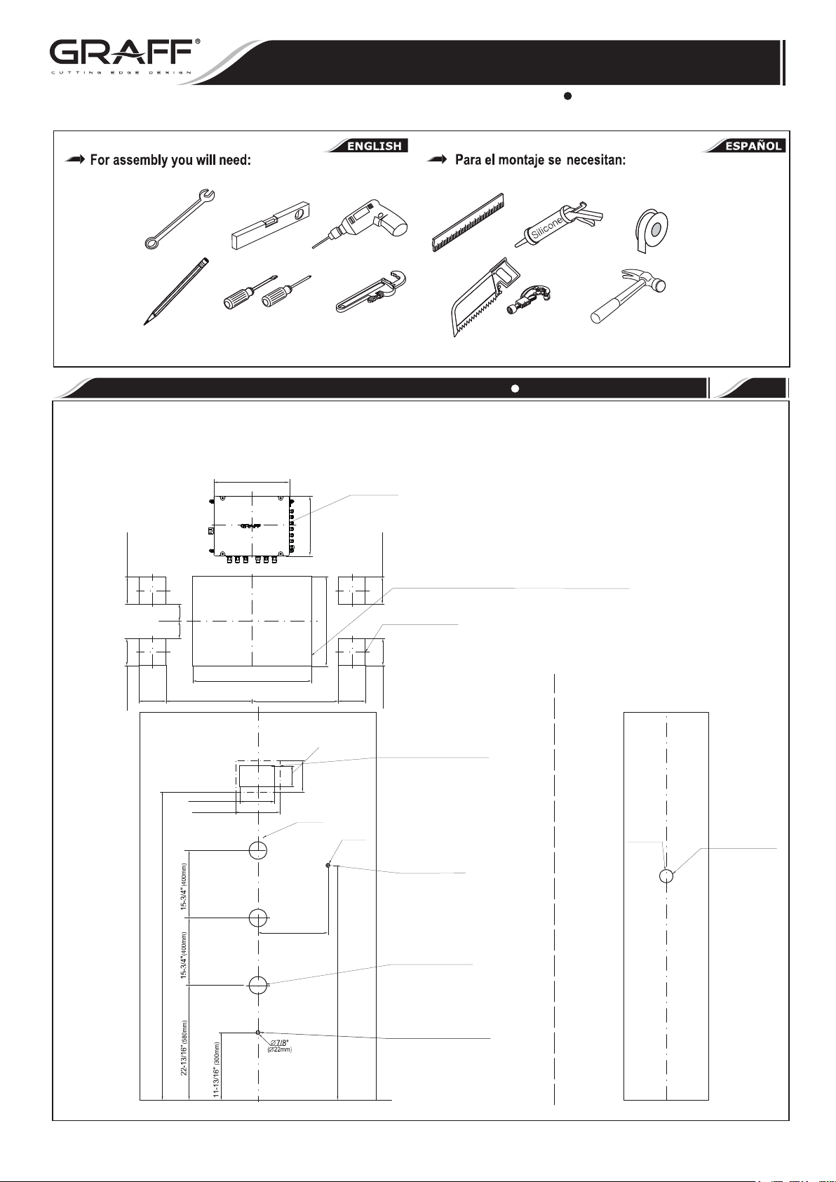
ASSEMBLY DIAGRAM ESQUEMA DE MONTAJE
1
Location and number of the receivers are discretionary – suggested. The distance between the particular receivers is determined by the dimensions of the devices
and the length of the service lines
La ubicación y el número de los recipientes son discrecionales - sugeridos. La distancia entre los distintos recipientes viene determinada por las dimensiones de los
equipos y la longitud de las líneas de servicio
(130mm)
5-1/8”
3-1/4”
3-1/4”
3-1/4”
(130mm)
5-1/8”
3-1/4”
(82,5mm)
(82,5mm)
(82,5mm)
(82,5mm)
16-1/4” (512,5mm)
6-7/16”(163mm)
8-1/8”(207mm)
15-5/16” (388mm)
22-1/2” (572mm)
12-1/8”(308mm)
16-1/4” (512,5mm)
5-7/8”
(150mm)
Ø2-3/4”
(Ø70mm)
16-3/4” (425mm)
(103mm)
4-1/16”
Control-Box
Box de control
3-1/4”
(82,5mm)
Ø7/8”
(Ø22mm)
(130mm)
5-1/8”
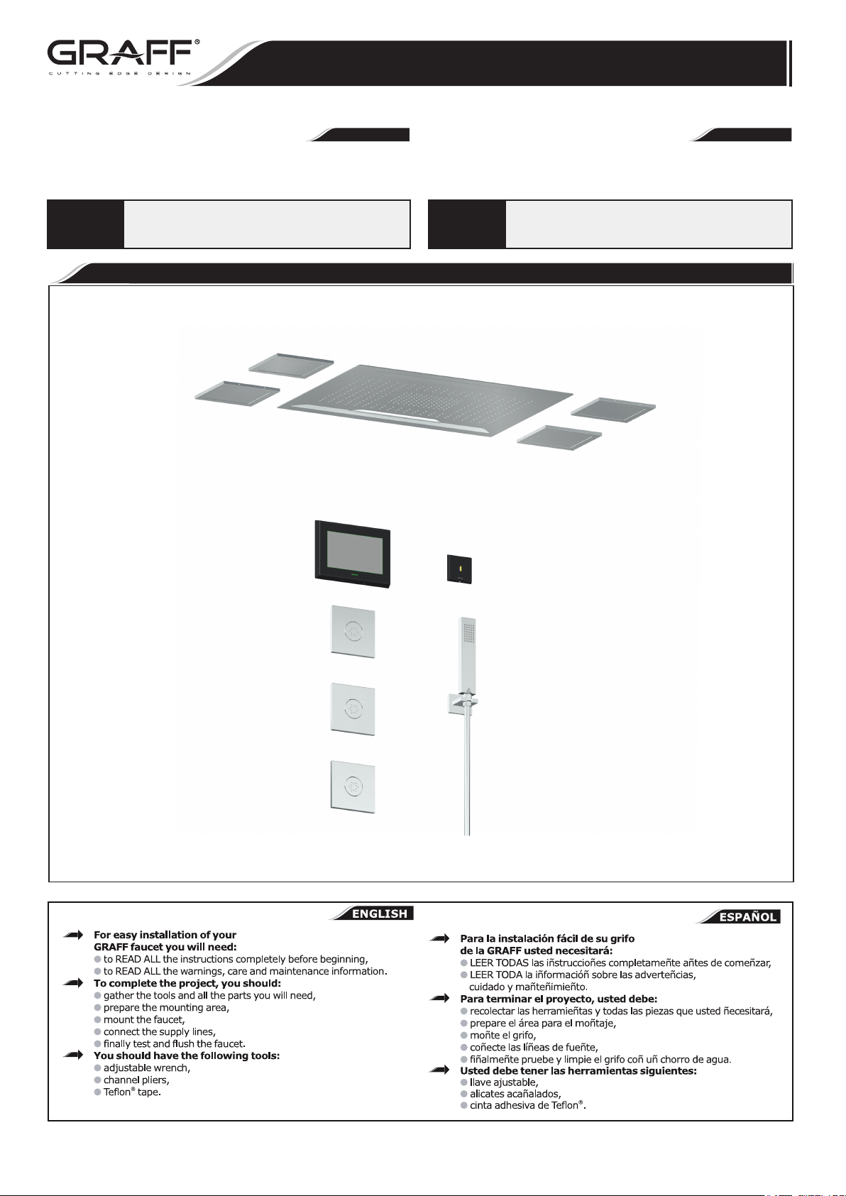
Multifunction Shower Head- Ceiling Mtd./Rain/LED Light/WaterFall/.
Alcachofa de ducha multifunción a tech-Iluvia/LED/cascada.
Set of 4 speakers
Set de 4 altavoces
(130mm)
5-1/8”
Control Touch Panel
Panel de control touch screen
Hand Shower
Ducha de mano
Size and spacing of assembly openings.
Tamaños y distribución de los orificios de montaje.
Ø1-7/8”
(Ø48mm)
USB-Port
Puerta-USB
IOG 5032.00
61” (1550mm)
16-5/16” (415mm)
43-5/16” (1100mm)
Body spray
Alcachofa de ducha lateral
Wall-mounted bathtub spout
Caño bañera de pared
2
Rev. 2 May 2017
ELECTRONIC THERMOSTATIC SYSTEM
SISTEMA TERMOSTÁTICO ELECTRÓNICO
This faucet complies with NSF61/9, ASME/ANSI A112.18.1
and CSA B 125 Standards.
Este grifo se encuentra conforme con losestandares de NSF61/9,
de ASME/ANSI A112.18.1 y de CSA B 125.
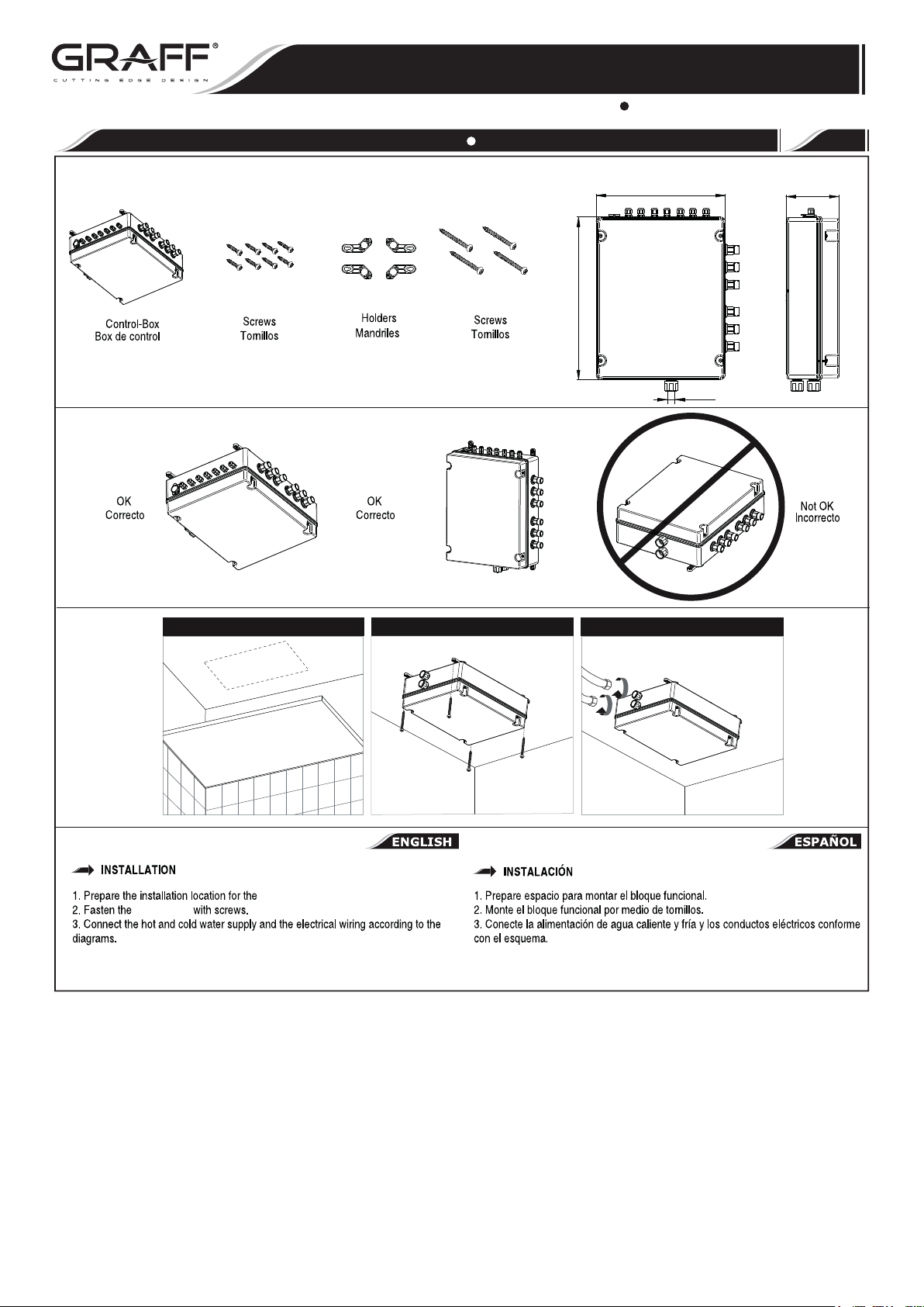
INSTALLATION OF THE CONTROL-BOX MONTAJE DEL BLOQUE FUNCIONAL
Installation Instructions Instrucciones de Instalación
2
15-5/16”
(388mm)
12-1/8”
(308mm)
G3/4”
4-15/16”
(126mm)
1 2
Control-Box.
Control-Box
NOTE! While designing the installation of the Control-Box, the installation method
enabling service access should be taken into account .
3
NOTA! Al diseñar la instalación de la Caja de Control, debe tenerse en cuenta el
método de instalación que permita el acceso al servicio.
IOG 5032.00
3
Rev. 2 May 2018
This faucet complies with NSF61/9, ASME/ANSI A112.18.1
and CSA B 125 Standards.
Este grifo se encuentra conforme con losestandares de NSF61/9,
de ASME/ANSI A112.18.1 y de CSA B 125.
HOT
COLD
ELECTRONIC THERMOSTATIC SYSTEM
SISTEMA TERMOSTÁTICO ELECTRÓNICO
Installation Instructions Instrucciones de Instalación
Block with a Key while screwing / unscrewing
Bloquear con una llave mientras atornilla / desatornilla
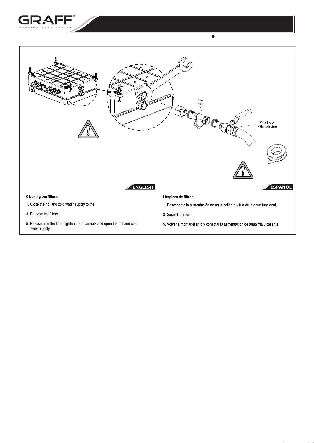
Failure to use the filters on cold and hot water inlets to the Control-Box may result in the breach of the terms of warranty. The filters need to
Si no se utilizan los filtros en las entradas de agua fría y caliente de la Caja de Control, se pueden incumplir los términos de la garantía. Se
be cleaned regularly every 2–3 months, depending on the quality of water in the system.
deben limpiar los filtros regularmente cada 2-3 meses, dependiendo de la calidad del agua en el sistema.
Control-Box.
2. Remove the wye strainer nuts.
4. Remove the contamination under running water.
2. Retire las tuercas del filtro de estrella.
4. Elimine la suciedad bajo el agua corriente.
Seal the screw connections.
Selle las uniones atornilladas.
IOG 5032.00
4
Rev. 2 May 2018
 Loading...