


 TECHNICAL MANUAL
GPC 13 SEER R-410A Package Air Conditioners with R-410A
•Refer to Service Manual RS6300011 (Horizontal)
for installation, operation, and troubleshooting information.
•All safety information must be followed as provided in the Service Manual.
•Refer to the appropriate Parts Catalog for part number information.
•Models listed on page 3.
This manual is to be used by qualified, professionally trained HVAC technicians only. Goodman does not assume any responsibility for property damage or personal injury due to improper service procedures or services performed by an unqualified person.
RT6322006r6
September 2010
Copyright © 2008 - 2010 Goodman Manufacturing Company, L.P.

PRODUCT IDENTIFICATION
The model and manufacturing number are used for positive identification of component parts used in manufacturing. Please use these numbers when requesting service or parts information.
G |
P |
C |
13 |
24 |
H |
4 |
1 |
A |
A |
|
|
|
|
|
|
|
|
|
|
|
VOLTAGE: |
|
|
|
||
BRAND: |
|
|
|
|
|
|
|
|
|
|
1: 208-230v |
|
MINOR REVISION: |
|||
G: Goodman® |
|
|
|
|
|
|
|
|
1ph/60Hz |
|
A: Initial Release |
|||||
Brand |
|
|
PRODUCT |
|
|
|
|
|
|
|
|
|
|
|
||
|
|
|
|
|
|
|
|
|
|
|
|
|
||||
|
|
FAMILY: |
|
|
|
|
|
|
|
|
|
|
|
|
||
|
|
|
|
|
|
|
|
|
|
|
|
|
|
|
||
|
|
|
|
|
|
|
|
|
|
|
|
|
|
|
||
|
|
|
C: Cooling |
|
|
|
|
|
|
|
|
|
|
|
|
|
|
|
|
|
|
|
|
|
|
REFRIGERANT: |
|
|
|
|
|
||
|
|
|
|
|
|
|
|
|
4: R-410A |
|
|
|
|
|
|
|
|
PRODUCT |
|
|
|
|
|
|
|
|
|
|
|
|
|
||
|
TYPE: |
|
PRODUCT |
|
|
|
|
|
|
|
|
|
|
|||
|
|
|
|
|
|
|
|
MAJOR REVISION: |
|
|||||||
|
Package Unit |
|
SERIES: |
|
|
|
|
|
|
|
||||||
|
|
|
CONFIGURATION: |
|
|
|
A: Initial Release |
|
||||||||
|
|
|
|
|
SEER Rating |
|
|
|
|
|
||||||
|
|
|
|
|
|
H: Horizontal |
|
|
|
B: 2nd Major Revision |
|
|||||
|
|
|
|
|
|
|
|
|
|
|
|
|||||
|
|
|
|
|
|
|
|
|
|
|
|
|
|
|
|
|
NOMINAL
CAPACITY
24: 24,000 BTUH 30: 30,000 BTUH 36: 36,000 BTUH 42: 42,000 BTUH
48:48,000 BTUH
49:48,000 BTUH
60:60,000 BTUH
WARNING |
HIGH VOLTAGE! |
Disconnect ALL power before servicing or installing this unit. Multiple power |
|
|
sources may be present. Failure to do so may cause property damage, personal |
|
injury or death. |
|
|
WARNING |
Goodman will not be responsible |
|
for any injury or property damage |
arising from improper service or service procedures. If you install or perform service on this unit, you assume responsibility for any personal injury or property damage which may result. Many jurisdictions require a license to install or service heating and air conditioning equipment.
Installation and repair of this unit WARNING should be performed ONLY by in-
dividuals meeting (at a minimum) the requirements of an "entry level technician" as specified by the Air-Conditioning, Heating, and Refrigeration Institute (AHRI). Attempting to install or repair this unit without such background may result in product damage, personal injury or death.
2
PRODUCT IDENTIFICATION
The model and manufacturing number are used for positive identification of component parts used in manufacturing. Please use these numbers when requesting service or parts information.
5MM
GPC1324H41AA GPC1324H41AB GPC1330H41AA GPC1330H41AB GPC1336H41AA GPC1336H41AB GPC1342H41AA GPC1342H41AB GPC1349H41AA GPC1348H41BA GPC1360H41BB
GPC1360H41BA
5 mm model specific information begins on page 29.
WARNING |
The United States Environmental Protection Agency (“EPA”) has issued various regulations re- |
garding the introduction and disposal of refrigerants introduced into this unit. Failure to follow |
|
|
these regulations may harm the environment and can lead to the imposition of substantial fines. |
|
These regulations may vary by jurisdiction. Should questions arise, contact your local EPA office. |
|
|
WARNING |
Do not connect or use any device |
that is not design certified by |
|
|
Goodman for use with this unit. |
Serious property damage, personal injury, reduced unit performance and/or hazardous conditions may result from the use of such non-approved devices.
WARNING To prevent the risk of property damage, personal injury, or death,
do not store combustible materials or use gasoline or other flammable liquids or vapors in the vicinity of this appliance.
3
PRODUCT DESIGN
GPC Package Cooling Units are designed for outdoor installations only in either residential or light commercial applications.
The connecting ductwork (Supply and Return) can be connected for either horizontal or vertical airflow. In the vertical application a matching Roof Curb is recommended.
A return air filter must be installed behind the return air grille(s) or provision must be made for a filter in an accessible location within the return air duct. The minimum filter area should not be less than those sizes listed in the Specification Section. Under no circumstances should the unit be operated without return air filters.
A 3/4” PVC pipe is provided for removal of condensate water from the indoor coil In order to provide proper condensate flow, a drain trap is supplied and shipped loose inside the unit for field installation. (Do not reduce the drain line size.)
Refrigerant flow control is achieved by use of restrictor orifices. GPC units use the FasTest Access Fitting System with a saddle that is either soldered to the suction and liquid lines or is fastened with a locking nut to the access fitting box (core) and then screwed into the saddle. Do not remove the core from the saddle until the refrigerant charge has been removed. Failure to do so could result in property damage or personal injury.
The single phase units use permanent split capacitor (PSC) design compressors. Starting components are therefore not required for these units. A low microfarad run capacitor assists the compressor to start and remains in the circuit during operation.
The outdoor fan and indoor blower motors are single phase capacitor type motors with the exception of the GPC1360H41* units which have X-13 indoor blower motors that are energized by a 24V signal from the thermostat and are constant torque motors with very low power consumption. The X-13 features an integral control module.
Air for condensing (cooling cycle) is drawn through the outdoor coil by a propeller fan, and is discharged vertically out the top of the unit. The outdoor coil is designed for .0 static. No additional restriction (ductwork) shall be applied.
Conditioned air is drawn through the filter(s), field installed, across the coil and back into the conditioned space by the indoor blower.
GPC1324-30H41* use Copeland Reciprocating Compressors.
-Due to their design Scroll Compressors are inherently more tolerant of liquid refrigerant. NOTE: Even though the compressor section of a Scroll compressor is more tolerant of liquid refrigerant, continued floodback or flooded start conditions may wash oil from the bearing surfaces causing premature bearing failure.
-Scroll Compressors use white oil which is compatible with 3GS oil which may be used if additional oil is required.
-Operating pressures and amp draws may differ from standard reciprocating compressors. This information may be found in the "Cooling Performance Data" section.
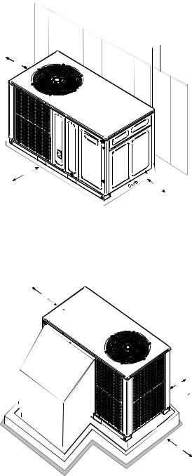
LocationandClearances
NOTE: To ensure proper condensate drainage, unit must be installed in a level position.
 10"
10"
36"
WALL
UNIT
36"
36"
Outside Slab Installation - Horizontal (H)
Minimumclearancesarerequiredtoavoidairrecirculationand keep the unit operating at peak efficiency.
36"
UNI
T
PL 
ENUM


24"
P |
|
|
|
B |
|
|
|
R |
|
L |
|
|
U |
|
|
A |
|
C |
|
|
|
T |
|
|
|
|
|
F |
|
|
|
|
O |
|
|
|
|
R |
|
|
|
|
M |
|
36"
Rooftop Installation - Horizontal (H)
4

PRODUCT DESIGN
In installations where the unit is installed above ground level and not serviceable from the ground (Example: Roof Top installations), the installer must provide service platform for service person with rails or guards in accordance with local codes or ordinances or in their absence with the latest edition of the Uniform Mechanical Code Section 305.
NOTE: Unit can also use roof curb.
Refer to Roof Curb Installation Instructions for proper curb installation. Curbing must be installed in compliance with the National Roofing Contractors Association Manual.
 WARNING
TO PREVENT POSSIBLE PROPERTY DAMAGE, THE UNIT SHOULD REMAIN IN AN UPRIGHT POSITION DURING ALL RIGGING AND MOVING OPERATIONS. TO FACILITATE LIFTING AND MOVING IF A CRANE IS USED, PLACE THE UNIT IN AN ADEQUATE CABLE SLING.
5

PRODUCT DIMENSIONS |
|
|
|
|
|
|
|
|
|
|
GPC13[24-60]H41** |
|||||||
|
|
|
|
|
|
|
|
|
|
|
|
|
|
|
|
|
|
|
|
|
|
|
|
|
|
|
|
|
|
|
|
|
|
|
|
|
|
|
|
|
|
|
|
|
|
|
|
|
|
|
|
|
|
|
|
|
|
|
|
|
|
|
|
|
|
|
|
|
|
|
|
|
|
|
|
|
|
|
|
|
|
|
|
|
|
|
|
|
|
|
|
|
|
|
|
|
|
|
|
|
|
|
|
|
|
|
|
|
|
|
|
|
|
|
|
|
|
|
|
|
|
|
|
|
|
|
|
|
|
|
|
|
66”
B
 A
A
Chassis |
Model |
A |
B |
|
|
|
|
|
|
Small |
GPC1324 |
33 |
30½ |
|
|
|
|
||
GPC1330 |
33 |
30½ |
||
|
||||
|
|
|
|
|
|
GPC1336 |
33 |
35½ |
|
Medium |
|
|
|
|
GPC1342 |
33 |
35½ |
||
|
|
|
|
|
|
GPC1349 |
33 |
35½ |
|
|
|
|
|
|
Large |
GPC1348 |
33 |
38½ |
|
|
|
|
|
|
|
GPC1360 |
33 |
38½ |
|
|
|
|
|
Dimensions in inches
6
ACCESSORIES |
GPC13[24-60]H41** |
|
|
|
|
Part Number |
Description |
|
|
|
|
OT18-60A |
Outdoor Thermostat Kit w/Lockout Stat |
|
|
|
|
OT/EHR18-60 |
Emergency Heat Relay Kit |
|
|
|
|
HKR |
Electric Heat Kit |
|
|
|
|
PCCP101-103 |
Roof Curb |
|
|
|
|
PCP101-103 |
Downflow Plenum Kit |
|
|
|
|
PCP101-103R8 |
Downflow Plenum Kit w/ R-8 Insulation |
|
|
|
|
GPCED101-103 |
Downflow Economizer for GPC-(H) A/C - To Be Used With PCP101-103 |
|
|
|
|
GPHED101-103 |
Downflow Economizer for GPH-(H) Heat Pump - To Be Used With PCP101-103 |
|
|
|
|
GPCEH101-103 |
Horizontal Economizer for GPC-(H) A/C |
|
|
|
|
GPHEH101-103 |
Horizontal Economizer for GPH-(H) Heat Pump |
|
|
|
|
PCMD101-103 |
Manual Damper - To Be Used With PCP101-103 |
|
|
|
|
PCMDM101-103 |
Motorized Damper - To Be Used With PCP101-103 |
|
|
|
|
GPHMD101-103 |
Manual Damper for Horizontal Applications |
|
|
|
|
SQRPCH101 |
Square to Round Adapters 16"&14" |
|
|
|
|
SQRPCH102-103 |
Square to Round Adapters 18"&14" |
|
|
|
|
SQRPC101 |
Square to Round Adapter - For Use With PCCP101-103 Curb 16" Rounds |
|
|
|
|
SQRPC102-103 |
Square to Round Adapter For Use With PCCP101-103 Curb 18" Rounds |
|
|
|
|
PCFR101-103 |
External Horizontal Filter Rack |
|
|
|
|
PCEF101-103 |
Elbow & Flashing w/ R-8 Liner |
|
|
|
|
CDK36 |
Flush Mount Concentric Duct Kit |
|
|
|
|
CDK36515 |
Flush Mount Concentric Duct Kit w/ Filter |
|
|
|
|
CDK36530 |
Step Down Concentric Duct Kit |
|
|
|
|
CDK36535 |
Step Down Concentric Duct Kit w/ Filter |
|
|
|
|
CDK4872 |
Flush Mount Concentric Duct Kit |
|
|
|
|
CDK4872515 |
Flush Mount Concentric Duct Kit w/ Filter |
|
|
|
|
CDK4872530 |
Step Down Concentric Duct Kit |
|
|
|
|
CDK4872535 |
Step Down Concentric Duct Kit w/ Filter |
|
|
|
|
7

PRODUCT DESIGN |
|
|
|
|
GPC13[24-60]H41** |
||||
ELECTRICAL DATA (*Blower Only, Heat Mode) |
|
||||||||
|
|
|
|
|
|
|
|
|
|
|
|
|
Circuit #1 |
|
Circuit #2 |
|
|||
Model and |
Minimum Circuit |
Maximum |
Minimum Circuit |
Maximum |
Actual |
||||
Overcurrent |
Overcurrent |
kW & BTU |
|||||||
Heat Kit Usage |
Ampacity |
|
Ampacity |
|
|||||
|
Protection (amps) |
|
Protection (amps) |
at 240V |
|||||
|
at 208 / 240V |
|
at 208 / 240V |
|
|||||
|
|
at 208 / 240V |
|
at 208 / 240V |
|
||||
|
|
|
|
|
|
|
|||
GPC1324H41* |
|
|
|
-- |
-- |
|
-- |
-- |
|
HKR05*,C* |
24 |
/ 27 |
|
30 / 30 |
-- |
|
-- |
4.75 / 16,200 |
|
HKR08*,C* |
33 |
/ 38 |
|
40 / 40 |
-- |
|
-- |
7.0 / 23,800 |
|
HKR10*,C* |
45 |
/ 51 |
|
60 / 60 |
-- |
|
-- |
9.5 / 32,400 |
|
GPC1330H41* |
2.4 |
/ 2.4 |
|
-- |
-- |
|
-- |
-- |
|
HKR05*,C* |
24 |
/ 27 |
|
30 / 30 |
-- |
|
-- |
4.75 / 16,200 |
|
HKR08*,C* |
34 |
/ 39 |
|
40 / 40 |
-- |
|
-- |
7.0 / 23,800 |
|
HKR10*,C* |
45 |
/ 52 |
|
60 / 60 |
-- |
|
-- |
9.5 / 32,400 |
|
HKR15*,C* |
45 |
/ 52 |
|
60 / 60 |
22 / 25 |
|
30 / 30 |
14.25 / 48,600 |
|
GPC1336H41* |
|
|
|
-- |
-- |
|
-- |
-- |
|
HKR05*,C* |
24 |
/ 27 |
|
30 / 30 |
-- |
|
-- |
4.75 / 16,200 |
|
HKR08*,C* |
34 |
/ 39 |
|
40 / 40 |
-- |
|
-- |
7.0 / 23,800 |
|
HKR10*,C* |
45 |
/ 52 |
|
60 / 60 |
-- |
|
-- |
9.5 / 32,400 |
|
HKR15*,C* |
45 |
/ 52 |
|
60 / 60 |
22 / 25 |
|
30 / 30 |
14.25 / 48,600 |
|
GPC1342H41* |
|
|
|
-- |
-- |
|
-- |
-- |
|
HKR05*,C* |
25 |
/ 27 |
|
30 / 30 |
-- |
|
-- |
4.75 / 16,200 |
|
HKR08*,C* |
34 |
/ 39 |
|
40 / 40 |
-- |
|
-- |
7.0 / 23,800 |
|
HKR10*,C* |
46 |
/ 52 |
|
60 / 60 |
-- |
|
-- |
9.5 / 32,400 |
|
HKR15*,C* |
46 |
/ 52 |
|
60 / 60 |
22 / 25 |
|
30 / 30 |
14.25 / 48,600 |
|
HKR20*,C* |
46 |
/ 52 |
|
60 / 60 |
43 / 49 |
|
60 / 60 |
19.5 / 66,500 |
|
GPC1348H41* |
|
|
|
-- |
-- |
|
-- |
-- |
|
HKR05*,C* |
25 |
/ 28 |
|
30 / 30 |
-- |
|
-- |
4.75 / 16,200 |
|
HKR08*,C* |
34 |
/ 40 |
|
40 / 40 |
-- |
|
-- |
7.0 / 23,800 |
|
HKR10*,C* |
46 |
/ 53 |
|
60 / 60 |
-- |
|
-- |
9.5 / 32,400 |
|
HKR15*,C* |
46 |
/ 52 |
|
60 / 60 |
22 / 25 |
|
30 / 30 |
14.25 / 48,600 |
|
HKR20*,C* |
46 |
/ 52 |
|
60 / 60 |
43 / 49 |
|
60 / 60 |
19.5 / 66,500 |
|
GPC1349H41* |
|
|
|
-- |
-- |
|
-- |
-- |
|
HKR05*,C* |
25 |
/ 28 |
|
30 / 30 |
-- |
|
-- |
4.75 / 16,200 |
|
HKR08*,C* |
34 |
/ 40 |
|
40 / 40 |
-- |
|
-- |
7.0 / 23,800 |
|
HKR10*,C* |
46 |
/ 53 |
|
60 / 60 |
-- |
|
-- |
9.5 / 32,400 |
|
HKR15*,C* |
46 |
/ 52 |
|
60 / 60 |
22 / 25 |
|
30 / 30 |
14.25 / 48,600 |
|
HKR20*,C* |
46 |
/ 52 |
|
60 / 60 |
43 / 49 |
|
60 / 60 |
19.5 / 66,500 |
|
GPC1360H41* |
|
|
|
-- |
-- |
|
-- |
-- |
|
HKR05*,C* |
26 |
/ 30 |
|
30 / 30 |
-- |
|
-- |
4.75 / 16,200 |
|
HKR08*,C* |
36 |
/ 40 |
|
40 / 40 |
-- |
|
-- |
7.0 / 23,800 |
|
HKR10*,C* |
48 |
/ 54 |
|
60 / 60 |
-- |
|
-- |
9.5 / 32,400 |
|
HKR15*,C* |
48 |
/ 54 |
|
60 / 60 |
22 / 25 |
|
30 / 30 |
14.25 / 48,600 |
|
HKR20*,C* |
48 |
/ 54 |
|
60 / 60 |
43 / 49 |
|
60 / 60 |
19.5 / 66,500 |
|
IMPORTANT NOTE: A separate power supply is required for the HKR heater kit.
All wires and overcurrent protection devices are sized for use with electric heaters only and without
WARNING refrigeration. If heaters are not installed with above wire size, overheating and fire could occur. See PACKAGE COOLING SPECIFICATIONS section for minimum circuit ampacity and maximum overcurrent
protection during refrigeration cycle.
8
BLOWER PERFORMANCE DATA |
GPC13[24-60]H41** |
Dry Coil Data
Model |
Speed |
|
Volts |
|
|
|
E.S.P (In. of H2O) |
|
|
|
|||
|
0.1 |
0.2 |
0.3 |
0.4 |
0.5 |
|
0.6 |
0.7 |
0.8 |
||||
|
|
|
|
|
|
||||||||
GPC1324H41** |
Low |
230 |
|
CFM |
680 |
640 |
590 |
555 |
505 |
|
440 |
340 |
- |
|
WATTS |
155 |
150 |
145 |
140 |
130 |
|
120 |
110 |
- |
|||
High |
230 |
|
|
||||||||||
|
|
|
|
|
|||||||||
|
Med |
230 |
|
CFM |
895 |
855 |
815 |
755 |
700 |
|
630 |
545 |
390 |
|
|
WATTS |
230 |
220 |
215 |
205 |
195 |
|
180 |
170 |
145 |
||
|
|
|
|
|
|||||||||
|
|
|
|
CFM |
1,185 |
1,130 |
1,070 |
1,010 |
930 |
|
850 |
760 |
650 |
|
|
|
|
WATTS |
350 |
340 |
325 |
310 |
295 |
|
280 |
265 |
245 |
GPC1330H41** |
Low |
230 |
|
CFM |
1,150 |
1,080 |
1,025 |
975 |
925 |
|
845 |
- |
- |
|
WATTS |
340 |
330 |
315 |
305 |
295 |
|
280 |
- |
- |
|||
High |
230 |
|
WATTS |
485 |
465 |
455 |
435 |
415 |
|
400 |
385 |
370 |
|
|
Med |
230 |
|
CFM |
1,335 |
1,275 |
1,205 |
1,135 |
1,075 |
|
985 |
910 |
845 |
|
|
WATTS |
425 |
415 |
400 |
385 |
370 |
|
350 |
330 |
310 |
||
|
|
|
|
CFM |
1,435 |
1,355 |
1,290 |
1,210 |
1,130 |
|
1,040 |
960 |
885 |
|
|
|
|
|
|
|
|
|
|
|
|
|
|
GPC1336H41** |
|
|
|
CFM |
1,180 |
1,125 |
1,075 |
1,020 |
955 |
|
875 |
655 |
- |
High |
230 |
|
WATTS |
495 |
480 |
465 |
440 |
425 |
|
400 |
385 |
370 |
|
|
Low |
230 |
|
WATTS |
335 |
325 |
315 |
305 |
295 |
|
275 |
240 |
- |
|
Med |
230 |
|
CFM |
1,350 |
1,280 |
1,205 |
1,130 |
1,050 |
|
985 |
910 |
845 |
|
|
WATTS |
435 |
420 |
405 |
385 |
375 |
|
350 |
330 |
310 |
||
|
|
|
|
CFM |
1,450 |
1,370 |
1,290 |
1,205 |
1,130 |
|
1,040 |
960 |
885 |
|
|
|
|
|
|
|
|
|
|
|
|
|
|
GPC1342H41** GPC1349H41** |
|
|
|
CFM |
1,425 |
1,410 |
1,355 |
1,310 |
1,245 |
|
1,170 |
1,080 |
- |
High |
230 |
|
WATTS |
765 |
755 |
735 |
715 |
695 |
|
670 |
640 |
615 |
|
|
Low |
230 |
|
WATTS |
450 |
445 |
430 |
420 |
405 |
|
390 |
370 |
- |
|
Med |
230 |
|
CFM |
1,620 |
1,595 |
1,545 |
1,485 |
1,425 |
|
1,345 |
1,250 |
1,160 |
|
|
WATTS |
550 |
540 |
525 |
510 |
495 |
|
475 |
450 |
425 |
||
|
|
|
|
CFM |
1,945 |
1,935 |
1,875 |
1,800 |
1,730 |
|
1,635 |
1,535 |
1,440 |
|
|
|
|
|
|
|
|
|
|
|
|
|
|
GPC1348H41** |
Low |
230 |
|
CFM |
1,425 |
1,410 |
1,355 |
1,310 |
1,245 |
|
1,170 |
1,080 |
- |
|
WATTS |
450 |
445 |
430 |
420 |
405 |
|
390 |
370 |
- |
|||
High |
230 |
|
WATTS |
785 |
780 |
765 |
745 |
720 |
|
705 |
665 |
625 |
|
|
Med |
230 |
|
CFM |
1,720 |
1,660 |
1,585 |
1,520 |
1,460 |
|
1,365 |
1,270 |
- |
|
|
WATTS |
560 |
555 |
540 |
530 |
520 |
|
490 |
470 |
- |
||
|
|
|
|
CFM |
2,110 |
2,060 |
1,980 |
1,895 |
1,795 |
|
1,705 |
1,590 |
1,500 |
|
|
|
|
|
|
|
|
|
|
|
|
|
|
GPC1360H41** |
|
|
|
CFM |
1,775 |
1,635 |
1,645 |
1,515 |
1,510 |
|
1,450 |
1,430 |
1,400 |
T4/T5 |
230 |
|
WATTS |
575 |
595 |
620 |
630 |
645 |
|
655 |
660 |
670 |
|
|
T1 |
230 |
|
WATTS |
395 |
420 |
435 |
445 |
455 |
|
465 |
470 |
475 |
|
T2/T3 |
230 |
|
CFM |
1,845 |
1,790 |
1,715 |
1,685 |
1,590 |
|
1,580 |
1,530 |
1,500 |
|
|
WATTS |
490 |
505 |
520 |
535 |
550 |
|
560 |
570 |
575 |
||
|
|
|
|
CFM |
2,025 |
1,900 |
1,840 |
1,780 |
1,725 |
|
1,650 |
1,620 |
1,580 |
|
|
|
|
|
|
|
|
|
|
|
|
|
|
NOTES:
1.Data shown is Dry Coil. Wet Coil Pressure Drop is approximate.
2.0.1" H2O, for 2 row indoor coil; 0.2” H2O, for 3 row indoor coil; and 0.3” H2O, for 4 row indoor coil.
3.Data shown does not include filter pressure drop, approx. 0.08” H2O.
4.Reduce airflow by 2% for 208V operation.
9

10 |
|
|
|
|
BTU OUTPUT vs TEMPERATURE RISE CHART |
|
|
|
BLOWER |
||||
100 |
|
|
|
|
|
|
|
|
|
|
|
||
90 |
|
|
600 CFM |
|
|
|
|
|
|
|
|||
|
|
|
|
|
|
|
|
|
|
|
|
DATA PERFORMANCE |
|
|
|
|
|
|
700 |
|
|
|
|
|
|
|
|
|
80 |
|
|
|
800 |
|
|
|
|
|
|
|
|
|
|
|
|
|
900 |
|
|
|
|
|
|
||
TEMPERATURERISE |
70 |
|
|
|
|
1000 |
|
|
|
|
|
|
|
|
|
|
|
|
1100 |
|
|
|
|
|
|
||
60 |
|
|
|
|
1200 |
|
|
|
|
|
|
||
|
|
|
|
|
|
|
|
|
|
|
|||
|
|
|
|
|
|
1400 |
|
|
|
|
|
||
50 |
|
|
|
|
|
1600 |
|
|
|
|
|
||
|
|
|
|
|
|
|
|
|
|
|
|||
|
|
|
|
|
|
1800 |
|
|
|
|
|||
|
|
|
|
|
|
|
2000 |
|
|
|
|
||
|
40 |
|
|
|
|
|
|
2200 |
|
|
|
|
|
|
|
|
|
|
|
|
|
2400 CFM |
|
|
|
|
|
|
30 |
|
|
|
|
|
|
|
|
FORMULAS |
|
||
|
|
|
|
|
|
|
|
|
|
|
|||
|
|
|
|
|
|
|
|
|
BTU OUTPUT = CFM x 1.08 x RISE |
|
|||
|
20 |
|
|
|
|
|
|
|
RISE = |
BTU OUTPUT |
÷ CFM |
|
|
|
|
|
|
|
|
|
|
|
1.08 |
|
|
||
|
|
|
|
|
|
|
|
|
|
|
|
|
|
|
10 |
|
|
|
|
|
|
|
|
|
|
|
|
|
30 |
40 |
50 |
60 |
70 |
80 |
90 |
100 |
110 |
120 |
130 |
140 |
150 |
|
|
|
|
|
|
OUTPUT BTU/HR x 1000 |
|
|
|
|
|
||
PACKAGE COOLING SPECIFICATIONS GPC13[24-30]H41AA
|
|
GPC1324H41* |
GPC1330H41* |
|
|
|
|
COOLING |
COOLING CAPACITY, BTUH |
24,000 |
28,600 |
CAPACITY |
SEER |
13.0 |
13.0 |
|
|
|
|
UNIT |
VOLTAGE (NAMEPLATE) |
208-230/1/60 |
208-230/1/60 |
ELECTRICAL |
AMPS (TOTAL) |
10.5 |
13.16 |
SPECIFICATION |
MINIMUM CIRCUIT AMPACITY |
12.5 |
15.6 |
|
MAXIMUM OVERCURRENT PROTECTION (1) |
20 |
25 |
COMPRESSOR |
TYPE |
RECIP |
RECIP |
|
RATED LOAD AMPS |
7.9 |
9.8 |
|
LOCKED ROTOR AMPS |
41 |
55 |
|
|
|
|
CONDENSER |
HORSEPOWER |
1/6 |
1/4 |
FAN MOTOR |
RPM |
815 |
830 |
|
FULL LOAD AMPS |
1.1 |
1.5 |
|
LOCKED ROTOR AMPS |
1.7 |
3.0 |
|
|
|
|
CONDENSER FAN |
BLADE DIAMETER (INCHES) / # OF BLADES |
22 / 3 |
22 / 3 |
|
|
|
|
CONDENSER |
FACE AREA - SQ. FT. |
13.4 |
13.4 |
COIL |
NUMBER OF ROWS |
1 |
1 |
|
FINS PER INCH |
24 |
24 |
|
|
|
|
EVAPORATOR |
HORSEPOWER - NO. OF SPEEDS |
1/4 - 3 |
1/3 - 3 |
BLOWER |
FULL LOAD AMPS |
1.5 |
1.86 |
MOTOR |
LOCKED ROTOR AMPS |
2.2 |
3.2 |
|
MOTOR SPEED TAP - COOLING |
MEDIUM |
LOW |
|
RPM |
1075 |
1075 |
|
|
|
|
EVAPORATOR |
DIAMETER X WIDTH (INCHES) |
9 x 6 |
9 x 6 |
BLOWER |
RATED SCFM COOLING |
815 |
1,080 |
|
MAX EXTERNAL STATIC PRESS ("w.c.) |
0.5 |
0.5 |
|
|
|
|
EVAPORATOR |
FACE AREA - SQ. FT. |
4.6 |
4.6 |
COIL |
NUMBER OF ROWS |
3 |
3 |
|
FINS PER INCH |
14 |
14 |
|
|
|
|
GENERAL |
FILTER SIZE - SQ. FT. * |
20 x 20 x 1 |
20 x 25 x 1 |
INFORMATION |
DRAIN SIZE (INCHES) |
3/4" |
3/4" |
|
EXPANSION DEVICE |
ORIFICE (0.059) |
ORRIFICE (0.060) |
|
REFRIGERANT CHARGE R-410A (Oz.) |
80 |
80 |
|
POWER SUPPLY CONDUIT KNOCKOUT SIZE (IN |
3/4, 1, 1-1/4 |
3/4, 1, 1-1/4 |
|
LOW VOLTAGE CONDUIT KNOCKOUT SIZE (IN.) |
1/2 |
1/2 |
|
SHIPPING WEIGHT LBS. |
310 |
310 |
|
OPERATING WEIGHT LBS. |
300 |
300 |
|
|
|
|
(1) Maximum Overcurrent Protection Device: MUST use Time Delay Fuse or HACR type Circuit Breaker of the same size as noted. * Calculated external filter size based on air velocity of 300 ft/min.
Wire size should be determined in accordance with National Electrical Codes. Extensive wire runs will require larger wire sizes.
Unit specifications are subject to change without notice. ALWAYS refer to the units serial plate for the most up-to-date general and electrical information.
IMPORTANT: While this data is presented as a guide, it is important to electrically connect the unit and properly size wires and fuses/circuit breakers in accordance with the National Electrical Code and/or all local codes. Data shown is w/o electric heaters.
11
PACKAGE COOLING SPECIFICATIONS |
GPC13[36-42]H41AA |
|||||
|
|
|
|
GPC1336H41* |
GPC1342H41* |
|
|
|
|
|
|
|
|
|
COOLING |
COOLING CAPACITY, BTUH |
|
36,000 |
41,000 |
|
|
CAPACITY |
SEER |
|
13.0 |
13.0 |
|
|
|
|
|
|
|
|
|
UNIT |
VOLTAGE (NAMEPLATE) |
|
208-230/1/60 |
208-230/1/60 |
|
|
ELECTRICAL |
AMPS (TOTAL) |
|
20.06 |
22.2 |
|
|
SPECIFICATION |
MINIMUM CIRCUIT AMPACITY |
|
24.2 |
26.6 |
|
|
|
MAXIMUM OVERCURRENT PROTECTION (1) |
|
40 |
40 |
|
|
COMPRESSOR |
TYPE |
|
SCROLL |
SCROLL |
|
|
|
RATED LOAD AMPS |
|
16.7 |
17.9 |
|
|
|
LOCKED ROTOR AMPS |
|
79 |
112 |
|
|
|
|
|
|
|
|
|
CONDENSER |
HORSEPOWER |
|
1/4 |
1/4 |
|
|
FAN MOTOR |
RPM |
|
830 |
1075 |
|
|
|
FULL LOAD AMPS |
|
1.5 |
1.4 |
|
|
|
LOCKED ROTOR AMPS |
|
3.0 |
2.9 |
|
|
|
|
|
|
|
|
|
CONDENSER FAN |
BLADE DIAMETER (INCHES) / # OF BLADES |
|
22 / 4 |
22 / 4 |
|
|
|
|
|
|
|
|
|
CONDENSER |
FACE AREA - SQ. FT. |
|
13.4 |
17.0 |
|
|
COIL |
NUMBER OF ROWS |
|
1 |
1 |
|
|
|
FINS PER INCH |
|
24 |
24 |
|
|
|
|
|
|
|
|
|
EVAPORATOR |
HORSEPOWER - NO. OF SPEEDS |
|
1/3 - 3 |
1/2 - 3 |
|
|
BLOWER |
FULL LOAD AMPS |
|
1.86 |
2.87 |
|
|
MOTOR |
LOCKED ROTOR AMPS |
|
3.2 |
4.9 |
|
|
|
MOTOR SPEED TAP - COOLING |
|
LOW |
LOW |
|
|
|
RPM |
|
1075 |
1075 |
|
|
|
|
|
|
|
|
|
EVAPORATOR |
DIAMETER X WIDTH (INCHES) |
|
9 x 8 |
10 x 8 |
|
|
BLOWER |
RATED SCFM COOLING |
|
1,205 |
1,410 |
|
|
|
MAX EXTERNAL STATIC PRESS ("w.c.) |
|
0.5 |
0.5 |
|
|
|
|
|
|
|
|
|
EVAPORATOR |
FACE AREA - SQ. FT. |
|
5.2 |
6.2 |
|
|
COIL |
NUMBER OF ROWS |
|
3 |
4 |
|
|
|
FINS PER INCH |
|
14 |
14 |
|
|
|
|
|
|
|
|
|
GENERAL |
FILTER SIZE - SQ. FT. * |
|
25 x 25 x 1 |
(2) 20 x 20 x 1 |
|
|
INFORMATION |
DRAIN SIZE (INCHES) |
|
3/4" |
3/4" |
|
|
|
EXPANSION DEVICE |
ORIFICE (0.065) |
ORIFICE (0.072) |
|
|
|
|
REFRIGERANT CHARGE R-410A (Oz.) |
|
85 |
105 |
|
|
|
POWER SUPPLY CONDUIT KNOCKOUT SIZE (IN.) |
|
3/4, 1, 1-1/4 |
3/4, 1, 1-1/4 |
|
|
|
LOW VOLTAGE CONDUIT KNOCKOUT SIZE (IN.) |
|
1/2 |
1/2 |
|
|
|
SHIPPING WEIGHT LBS. |
|
370 |
370 |
|
|
|
OPERATING WEIGHT LBS. |
|
360 |
360 |
|
|
|
|
|
|
|
|
(1) Maximum Overcurrent Protection Device: MUST use Time Delay Fuse or HACR type Circuit Breaker of the same size as noted.
* Calculated external filter size based on air velocity of 300 ft/min.
Wire size should be determined in accordance with National Electrical Codes. Extensive wire runs will require larger wire sizes.
Unit specifications are subject to change without notice. ALWAYS refer to the units serial plate for the most up-to-date general and electrical information.
IMPORTANT: While this data is presented as a guide, it is important to electrically connect the unit and properly size wires and fuses/circuit breakers in accordance with the National Electrical Code and/or all local codes. Data shown is w/o electric heaters.
12
PACKAGE COOLING SPECIFICATIONS GPC13[48-60]H41BA
|
|
GPC1348H41B* |
GPC1360H41B* |
|
|
|
|
COOLING |
COOLING CAPACITY, BTUH |
45,500 |
57,500 |
CAPACITY |
SEER |
13.0 |
13.0 |
|
|
|
|
UNIT |
VOLTAGE (NAMEPLATE) |
208-230/1/60 |
208-230/1/60 |
ELECTRICAL |
AMPS (TOTAL) |
24.17 |
33.6 |
SPECIFICATION |
MINIMUM CIRCUIT AMPACITY |
29.2 |
40.2 |
|
MAXIMUM OVERCURRENT PROTECTION (1) |
45 |
60 |
COMPRESSOR |
TYPE |
SCROLL |
SCROLL |
|
RATED LOAD AMPS |
19.9 |
26.4 |
|
LOCKED ROTOR AMPS |
109 |
134 |
|
|
|
|
CONDENSER |
HORSEPOWER |
1/4 |
1/4 |
FAN MOTOR |
RPM |
1075 |
1075 |
|
FULL LOAD AMPS |
1.4 |
1.4 |
|
LOCKED ROTOR AMPS |
2.9 |
2.9 |
|
|
|
|
CONDENSER FAN |
BLADE DIAMETER (INCHES) /# OF BLADES |
22 / 4 |
22 / 4 |
|
|
|
|
CONDENSER |
FACE AREA - SQ. FT. |
19.1 |
19.1 |
COIL |
NUMBER OF ROWS |
1 |
2 |
|
FINS PER INCH |
21 |
16 |
|
|
|
|
EVAPORATOR |
HORSEPOWER - NO. OF SPEEDS |
1/2 - 3 |
3/4 - 3 |
BLOWER |
FULL LOAD AMPS |
2.87 |
5.8 |
MOTOR |
LOCKED ROTOR AMPS |
4.9 |
NA |
|
MOTOR SPEED TAP - COOLING |
MEDIUM |
T2 |
|
RPM |
1075 |
1075 |
|
|
|
|
EVAPORATOR |
DIAMETER X WIDTH (INCHES) |
10 x 8 |
11 x 8 |
BLOWER |
RATED SCFM COOLING |
1,585 |
1,850 |
|
MAX EXTERNAL STATIC PRESS ("w.c.) |
0.5 |
0.5 |
|
|
|
|
EVAPORATOR |
FACE AREA - SQ. FT. |
6.2 |
7.0 |
COIL |
NUMBER OF ROWS |
4 |
4 |
|
FINS PER INCH |
14 |
14 |
|
|
|
|
GENERAL |
FILTER SIZE - SQ. FT. * |
(2) 20 x 20 x 1 |
(2) 20 x 25 x 1 |
|
|||
INFORMATION |
DRAIN SIZE (INCHES) |
3/4" |
3/4" |
|
|||
|
EXPANSION DEVICE |
ORRIFICE (0.076) |
ORIFICE (0.088) |
|
REFRIGERANT CHARGE R-410A (Oz.) |
110 |
160 |
|
POWER SUPPLY CONDUIT KNOCKOUT SIZE (IN.) |
3/4, 1, 1-1/4 |
3/4, 1, 1-1/4 |
|
LOW VOLTAGE CONDUIT KNOCKOUT SIZE (IN.) |
1/2 |
1/2 |
|
SHIPPING WEIGHT LBS. |
400 |
400 |
|
OPERATING WEIGHT LBS. |
390 |
390 |
|
|
|
|
(1) Maximum Overcurrent Protection Device: MUST use Time Delay Fuse or HACR type Circuit Breaker of the same size as noted. * Calculated external filter size based on air velocity of 300 ft/min.
Wire size should be determined in accordance with National Electrical Codes. Extensive wire runs will require larger wire sizes.
Unit specifications are subject to change without notice. ALWAYS refer to the units serial plate for the most up-to-date general and electrical information.
IMPORTANT: While this data is presented as a guide, it is important to electrically connect the unit and properly size wires and fuses/circuit breakers in accordance with the National Electrical Code and/or all local codes. Data shown is w/o electric heaters.
13

14
MODEL: GPC1324H41A* |
EXPANDED PERFORMANCE DATA |
COOLING OPERATION |
Design Subcooling, 12±3 °F @ the liquid access fitting connection AHRI 95 test conditions. Design Superheat 8±3 °F @ the compressor suction access fitting connection.
|
|
|
|
|
|
|
|
|
|
|
|
|
|
|
|
Outdoor Ambient Temperature |
|
|
|
|
|
|
|
|
|
|
||||
|
|
|
|
|
65 |
|
|
75 |
|
|
|
|
85 |
|
|
95 |
|
|
|
105 |
|
|
115 |
|
||||||
|
|
|
|
|
|
|
|
|
|
|
|
|
|
Entering Indoor Wet |
Bulb Temperature |
|
|
|
|
|
|
|
|
|
|
|||||
IDB* |
Airflow |
|
59 |
63 |
|
67 |
71 |
59 |
63 |
|
67 |
71 |
59 |
63 |
|
67 |
71 |
59 |
63 |
|
67 |
71 |
59 |
63 |
67 |
71 |
59 |
63 |
67 |
71 |
|
|
MBh |
23.5 |
24.4 |
|
26.7 |
- |
23.0 |
23.8 |
|
26.1 |
- |
22.4 |
23.2 |
|
25.5 |
- |
21.9 |
22.7 |
|
24.8 |
- |
20.8 |
21.5 |
23.6 |
- |
19.3 |
20.0 |
21.9 |
- |
|
|
S/T |
0.78 |
0.65 |
0.45 |
- |
0.81 |
0.68 |
|
0.47 |
- |
0.83 |
0.70 |
0.48 |
- |
0.86 |
0.72 |
|
0.50 |
- |
0.89 |
0.74 |
0.52 |
- |
0.90 |
0.75 |
0.52 |
- |
||
|
|
Delta T |
17 |
15 |
11 |
- |
17 |
15 |
|
11 |
- |
18 |
15 |
12 |
- |
18 |
15 |
|
12 |
- |
17 |
15 |
11 |
- |
16 |
14 |
11 |
- |
||
|
980 |
|
|
|
|
|
|
|
|
|
|
|
|
|
|
|
|
|
|
|
|
|
|
|
|
|
|
|
||
|
KW |
1.71 |
1.74 |
1.79 |
- |
1.83 |
1.87 |
|
1.93 |
- |
1.94 |
1.98 |
2.05 |
- |
2.04 |
2.08 |
|
2.15 |
- |
2.12 |
2.17 |
2.24 |
- |
2.20 |
2.24 |
2.32 |
- |
|||
|
|
AMPS |
7.1 |
7.3 |
7.5 |
- |
7.6 |
7.8 |
|
8.0 |
- |
8.2 |
8.3 |
8.6 |
- |
8.7 |
8.8 |
|
9.1 |
- |
9.1 |
9.3 |
9.6 |
- |
9.6 |
9.8 |
10.1 |
- |
||
|
|
HI PR |
222 |
239 |
252 |
- |
249 |
268 |
|
283 |
- |
283 |
305 |
322 |
- |
323 |
347 |
|
367 |
- |
363 |
391 |
413 |
- |
401 |
432 |
456 |
- |
||
|
|
LO PR |
112 |
119 |
130 |
- |
118 |
126 |
|
137 |
- |
123 |
131 |
143 |
- |
129 |
137 |
|
150 |
- |
135 |
144 |
157 |
- |
140 |
149 |
163 |
- |
||
|
|
MBh |
22.8 |
23.7 |
25.9 |
- |
22.3 |
23.1 |
|
25.3 |
- |
21.8 |
22.6 |
24.7 |
- |
21.2 |
22.0 |
|
24.1 |
- |
20.2 |
20.9 |
22.9 |
- |
18.7 |
19.4 |
21.2 |
- |
||
|
|
S/T |
0.75 |
0.62 |
0.43 |
- |
0.77 |
0.65 |
|
0.45 |
- |
0.79 |
0.66 |
0.46 |
- |
0.82 |
0.68 |
|
0.47 |
- |
0.85 |
0.71 |
0.49 |
- |
0.86 |
0.72 |
0.50 |
- |
||
|
|
Delta T |
18 |
16 |
12 |
- |
18 |
16 |
|
12 |
- |
18 |
16 |
12 |
- |
18 |
16 |
|
12 |
- |
18 |
16 |
12 |
- |
17 |
15 |
11 |
- |
||
70 |
875 |
KW |
1.69 |
1.73 |
1.78 |
- |
1.82 |
1.85 |
|
1.91 |
- |
1.93 |
1.97 |
2.03 |
- |
2.02 |
2.07 |
|
2.13 |
- |
2.11 |
2.15 |
2.22 |
- |
2.18 |
2.23 |
2.30 |
- |
||
|
|
AMPS |
7.1 |
7.2 |
7.4 |
- |
7.6 |
7.7 |
|
7.9 |
- |
8.1 |
8.3 |
8.5 |
- |
8.6 |
8.8 |
|
9.0 |
- |
9.1 |
9.3 |
9.5 |
- |
9.5 |
9.8 |
10.0 |
- |
||
|
|
HI PR |
220 |
237 |
250 |
- |
247 |
265 |
|
280 |
- |
281 |
302 |
319 |
- |
320 |
344 |
|
363 |
- |
360 |
387 |
409 |
- |
397 |
427 |
451 |
- |
||
|
|
LO PR |
111 |
118 |
129 |
- |
117 |
125 |
|
136 |
- |
122 |
130 |
141 |
- |
128 |
136 |
|
149 |
- |
134 |
143 |
156 |
- |
139 |
148 |
161 |
- |
||
|
|
MBh |
21.7 |
22.5 |
24.6 |
- |
21.2 |
22.0 |
|
24.1 |
- |
20.7 |
21.4 |
23.5 |
- |
20.2 |
20.9 |
|
22.9 |
- |
19.2 |
19.9 |
21.8 |
- |
17.8 |
18.4 |
20.2 |
- |
||
|
|
S/T |
0.72 |
0.60 |
0.41 |
- |
0.74 |
0.62 |
|
0.43 |
- |
0.76 |
0.64 |
0.44 |
- |
0.79 |
0.66 |
|
0.45 |
- |
0.81 |
0.68 |
0.47 |
- |
0.82 |
0.69 |
0.48 |
- |
||
|
770 |
Delta T |
19 |
16 |
12 |
- |
19 |
16 |
|
12 |
- |
19 |
16 |
12 |
- |
19 |
16 |
|
12 |
- |
19 |
16 |
12 |
- |
17 |
15 |
11 |
- |
||
|
KW |
1.67 |
1.70 |
1.75 |
- |
1.79 |
1.83 |
|
1.88 |
- |
1.90 |
1.94 |
2.00 |
- |
1.99 |
2.03 |
|
2.10 |
- |
2.07 |
2.12 |
2.19 |
- |
2.14 |
2.19 |
2.26 |
- |
|||
|
|
AMPS |
7.0 |
7.1 |
7.3 |
- |
7.4 |
7.6 |
|
7.8 |
- |
8.0 |
8.2 |
8.4 |
- |
8.5 |
8.6 |
|
8.9 |
- |
8.9 |
9.1 |
9.4 |
- |
9.4 |
9.6 |
9.9 |
- |
||
|
|
HI PR |
215 |
232 |
245 |
- |
242 |
260 |
|
275 |
- |
275 |
296 |
312 |
- |
313 |
337 |
|
356 |
- |
352 |
379 |
400 |
- |
389 |
419 |
442 |
- |
||
|
|
LO PR |
109 |
116 |
126 |
- |
115 |
122 |
|
133 |
- |
119 |
127 |
139 |
- |
125 |
133 |
|
146 |
- |
131 |
140 |
153 |
- |
136 |
145 |
158 |
- |
||
|
|
|
|
|
|
|
|
|
|
|
|
|
|
|
|
|
|
|
|
|
|
|
|
|
|
|
|
|
|
|
|
|
MBh |
23.9 |
24.6 |
26.7 |
28.6 |
23.4 |
24.1 |
|
26.0 |
27.9 |
22.8 |
23.5 |
25.4 |
27.3 |
22.2 |
22.9 |
|
24.8 |
26.6 |
21.1 |
21.8 |
23.6 |
25.3 |
19.6 |
20.2 |
21.8 |
23.4 |
||
|
|
S/T |
0.89 |
0.80 |
0.60 |
0.39 |
0.92 |
0.83 |
|
0.62 |
0.40 |
0.95 |
0.85 |
0.64 |
0.41 |
0.98 |
0.87 |
|
0.66 |
0.43 |
1.00 |
0.91 |
0.69 |
0.44 |
1.00 |
0.91 |
0.69 |
0.45 |
||
|
980 |
Delta T |
20 |
18 |
15 |
10 |
20 |
19 |
|
15 |
11 |
20 |
19 |
15 |
11 |
20 |
19 |
|
15 |
11 |
20 |
19 |
15 |
10 |
18 |
17 |
14 |
10 |
||
|
KW |
1.72 |
1.75 |
1.81 |
1.86 |
1.85 |
1.88 |
|
1.94 |
2.00 |
1.96 |
2.00 |
2.06 |
2.13 |
2.06 |
2.10 |
|
2.17 |
2.24 |
2.14 |
2.19 |
2.26 |
2.33 |
2.21 |
2.26 |
2.34 |
2.41 |
|||
|
|
AMPS |
7.2 |
7.3 |
7.5 |
7.8 |
7.7 |
7.8 |
|
8.1 |
8.3 |
8.2 |
8.4 |
8.7 |
8.9 |
8.7 |
8.9 |
|
9.2 |
9.5 |
9.2 |
9.4 |
9.7 |
10.0 |
9.7 |
9.9 |
10.2 |
10.6 |
||
|
|
HI PR |
224 |
241 |
255 |
266 |
252 |
271 |
|
286 |
298 |
286 |
308 |
325 |
339 |
326 |
351 |
|
371 |
386 |
367 |
395 |
417 |
435 |
405 |
436 |
461 |
480 |
||
|
|
LO PR |
113 |
120 |
131 |
140 |
120 |
127 |
|
139 |
148 |
124 |
132 |
144 |
154 |
131 |
139 |
|
152 |
161 |
137 |
146 |
159 |
169 |
141 |
151 |
164 |
175 |
||
|
|
MBh |
23.2 |
23.9 |
25.9 |
27.8 |
22.7 |
23.4 |
|
25.3 |
27.1 |
22.1 |
22.8 |
24.7 |
26.5 |
21.6 |
22.2 |
|
24.1 |
25.8 |
20.5 |
21.1 |
22.9 |
24.5 |
19.0 |
19.6 |
21.2 |
22.7 |
||
|
|
S/T |
0.85 |
0.76 |
0.57 |
0.37 |
0.88 |
0.79 |
|
0.60 |
0.38 |
0.90 |
0.81 |
0.61 |
0.39 |
0.93 |
0.83 |
|
0.63 |
0.41 |
0.97 |
0.86 |
0.65 |
0.42 |
0.97 |
0.87 |
0.66 |
0.42 |
||
75 |
875 |
Delta T |
21 |
19 |
16 |
11 |
21 |
19 |
|
16 |
11 |
21 |
19 |
16 |
11 |
21 |
19 |
|
16 |
11 |
21 |
19 |
16 |
11 |
19 |
18 |
15 |
10 |
||
KW |
1.71 |
1.74 |
1.79 |
1.85 |
1.83 |
1.87 |
|
1.93 |
1.99 |
1.94 |
1.98 |
2.05 |
2.11 |
2.04 |
2.08 |
|
2.15 |
2.22 |
2.12 |
2.17 |
2.24 |
2.31 |
2.20 |
2.24 |
2.32 |
2.39 |
||||
|
|
AMPS |
7.1 |
7.3 |
7.5 |
7.7 |
7.6 |
7.8 |
|
8.0 |
8.2 |
8.2 |
8.3 |
8.6 |
8.9 |
8.7 |
8.8 |
|
9.1 |
9.4 |
9.1 |
9.3 |
9.6 |
9.9 |
9.6 |
9.8 |
10.1 |
10.5 |
||
|
|
HI PR |
222 |
239 |
252 |
263 |
249 |
268 |
|
283 |
295 |
283 |
305 |
322 |
336 |
323 |
347 |
|
367 |
383 |
363 |
391 |
413 |
430 |
401 |
432 |
456 |
476 |
||
|
|
LO PR |
112 |
119 |
130 |
139 |
118 |
126 |
|
137 |
146 |
123 |
131 |
143 |
152 |
129 |
137 |
|
150 |
160 |
135 |
144 |
157 |
168 |
140 |
149 |
163 |
173 |
||
|
|
MBh |
22.1 |
22.7 |
24.6 |
26.4 |
21.5 |
22.2 |
|
24.0 |
25.8 |
21.0 |
21.7 |
23.4 |
25.2 |
20.5 |
21.1 |
|
22.9 |
24.5 |
19.5 |
20.1 |
21.7 |
23.3 |
18.1 |
18.6 |
20.1 |
21.6 |
||
|
|
S/T |
0.81 |
0.73 |
0.55 |
0.35 |
0.84 |
0.75 |
|
0.57 |
0.37 |
0.86 |
0.77 |
0.59 |
0.38 |
0.89 |
0.80 |
|
0.60 |
0.39 |
0.93 |
0.83 |
0.63 |
0.40 |
0.93 |
0.84 |
0.63 |
0.41 |
||
|
770 |
Delta T |
21 |
20 |
16 |
11 |
22 |
20 |
|
16 |
11 |
22 |
20 |
16 |
11 |
22 |
20 |
|
16 |
11 |
22 |
20 |
16 |
11 |
20 |
19 |
15 |
10 |
||
|
KW |
1.68 |
1.71 |
1.77 |
1.82 |
1.80 |
1.84 |
|
1.90 |
1.96 |
1.91 |
1.95 |
2.01 |
2.08 |
2.01 |
2.05 |
|
2.12 |
2.18 |
2.09 |
2.14 |
2.20 |
2.28 |
2.16 |
2.21 |
2.28 |
2.35 |
|||
|
|
AMPS |
7.0 |
7.2 |
7.4 |
7.6 |
7.5 |
7.7 |
|
7.9 |
8.1 |
8.0 |
8.2 |
8.5 |
8.7 |
8.5 |
8.7 |
|
9.0 |
9.3 |
9.0 |
9.2 |
9.5 |
9.8 |
9.5 |
9.7 |
10.0 |
10.3 |
||
|
|
HI PR |
218 |
234 |
247 |
258 |
244 |
263 |
|
278 |
289 |
278 |
299 |
316 |
329 |
316 |
340 |
|
360 |
375 |
356 |
383 |
404 |
422 |
393 |
423 |
447 |
466 |
||
|
|
LO PR |
110 |
117 |
128 |
136 |
116 |
123 |
|
135 |
143 |
121 |
128 |
140 |
149 |
127 |
135 |
|
147 |
157 |
133 |
141 |
154 |
164 |
137 |
146 |
159 |
170 |
||
|
* IDB: |
Entering Indoor Dry Bulb Temperature |
|
|
|
NOTE: Shaded area is ACCA (TVA) conditions |
|
|
|
|
|
|
|
|
|
|
|
|
||||||||||||
High and low pressures are measured at the liquid and suction access fittings.
DATA PERFORMANCE COOLING
GPC1324H41AA

15
MODEL: GPC1324H41A* |
EXPANDED PERFORMANCE DATA |
COOLING OPERATION |
Design Subcooling, 12±3 °F @ the liquid access fitting connection AHRI 95 test conditions. Design Superheat 8±3 °F @ the compressor suction access fitting connection.
|
|
|
|
|
|
|
|
|
|
|
|
|
|
|
|
|
Outdoor Ambient Temperature |
|
|
|
|
|
|
|
|
|
|
|
|||||
|
|
|
|
|
|
65 |
|
|
|
75 |
|
|
|
85 |
|
|
|
95 |
|
|
|
105 |
|
|
115 |
|
|
||||||
|
|
|
|
|
|
|
|
|
|
|
|
|
|
|
Entering Indoor Wet |
Bulb Temperature |
|
|
|
|
|
|
|
|
|
|
|
||||||
IDB* |
|
Airflow |
|
59 |
63 |
|
67 |
71 |
59 |
63 |
|
67 |
71 |
59 |
63 |
|
67 |
71 |
|
59 |
63 |
|
67 |
71 |
59 |
63 |
67 |
71 |
59 |
63 |
67 |
71 |
|
|
|
|
MBh |
24.3 |
24.9 |
|
26.6 |
28.4 |
23.8 |
24.3 |
|
26.0 |
27.7 |
23.2 |
23.7 |
|
25.3 |
27.1 |
|
22.6 |
23.1 |
|
24.7 |
26.4 |
21.5 |
22.0 |
23.5 |
25.1 |
19.9 |
20.4 |
21.8 |
23.3 |
|
|
|
|
S/T |
1.00 |
0.92 |
0.75 |
0.56 |
1.00 |
0.95 |
0.77 |
0.58 |
1.00 |
1.00 |
0.79 |
0.59 |
|
1.00 |
1.00 |
|
0.82 |
0.61 |
1.00 |
1.00 |
0.85 |
0.63 |
1.00 |
1.00 |
0.86 |
0.64 |
|
|||
|
|
|
Delta T |
23 |
21 |
19 |
15 |
22 |
22 |
19 |
15 |
22 |
22 |
19 |
15 |
|
21 |
22 |
|
19 |
15 |
20 |
21 |
19 |
15 |
19 |
19 |
17 |
14 |
|
|||
|
|
980 |
|
|
|
|
|
|
|
|
|
|
|
|
|
|
|
|
|
|
|
|
|
|
|
|
|
|
|
|
|||
|
|
KW |
1.73 |
1.77 |
1.82 |
1.88 |
1.86 |
1.90 |
1.96 |
2.02 |
1.97 |
2.02 |
2.08 |
2.15 |
|
2.07 |
2.12 |
|
2.19 |
2.26 |
2.16 |
2.21 |
2.28 |
2.35 |
2.23 |
2.28 |
2.36 |
2.43 |
|
||||
|
|
|
AMPS |
7.2 |
7.4 |
7.6 |
7.8 |
7.7 |
7.9 |
8.1 |
8.4 |
8.3 |
8.5 |
8.7 |
9.0 |
|
8.8 |
9.0 |
|
9.3 |
9.6 |
9.3 |
9.5 |
9.8 |
10.1 |
9.8 |
10.0 |
10.3 |
10.7 |
|
|||
|
|
|
HI PR |
227 |
244 |
257 |
269 |
254 |
274 |
289 |
301 |
289 |
311 |
329 |
343 |
|
329 |
354 |
|
374 |
390 |
371 |
399 |
421 |
439 |
409 |
441 |
465 |
485 |
|
|||
|
|
|
LO PR |
114 |
122 |
133 |
141 |
121 |
128 |
140 |
149 |
126 |
134 |
146 |
155 |
|
132 |
140 |
|
153 |
163 |
138 |
147 |
160 |
171 |
143 |
152 |
166 |
177 |
|
|||
|
|
|
MBh |
23.6 |
24.1 |
25.8 |
27.6 |
23.1 |
23.6 |
25.2 |
26.9 |
22.5 |
23.0 |
24.6 |
26.3 |
|
22.0 |
22.5 |
|
24.0 |
25.7 |
20.9 |
21.3 |
22.8 |
24.4 |
19.3 |
19.8 |
21.1 |
22.6 |
|
|||
|
|
|
S/T |
0.93 |
0.87 |
0.71 |
0.53 |
0.97 |
0.91 |
0.74 |
0.55 |
0.99 |
0.93 |
0.76 |
0.56 |
|
1.00 |
0.96 |
|
0.78 |
0.58 |
1.00 |
0.99 |
0.81 |
0.61 |
1.00 |
1.00 |
0.82 |
0.61 |
|
|||
80 |
|
875 |
Delta T |
23 |
22 |
19 |
15 |
23 |
22 |
20 |
16 |
23 |
22 |
20 |
16 |
|
23 |
23 |
|
20 |
16 |
22 |
22 |
19 |
15 |
20 |
21 |
18 |
14 |
|
|||
|
KW |
1.72 |
1.75 |
1.81 |
1.86 |
1.85 |
1.88 |
1.94 |
2.00 |
1.96 |
2.00 |
2.06 |
2.13 |
|
2.06 |
2.10 |
|
2.17 |
2.24 |
2.14 |
2.19 |
2.26 |
2.33 |
2.21 |
2.26 |
2.34 |
2.41 |
|
|||||
|
|
|
AMPS |
7.2 |
7.3 |
7.5 |
7.8 |
7.7 |
7.8 |
8.1 |
8.3 |
8.2 |
8.4 |
8.7 |
8.9 |
|
8.7 |
8.9 |
|
9.2 |
9.5 |
9.2 |
9.4 |
9.7 |
10.0 |
9.7 |
9.9 |
10.2 |
10.6 |
|
|||
|
|
|
HI PR |
224 |
241 |
255 |
266 |
252 |
271 |
286 |
298 |
286 |
308 |
325 |
339 |
|
326 |
351 |
|
371 |
386 |
367 |
395 |
417 |
435 |
405 |
436 |
461 |
480 |
|
|||
|
|
|
LO PR |
113 |
120 |
131 |
140 |
120 |
127 |
139 |
148 |
124 |
132 |
144 |
154 |
|
131 |
139 |
|
152 |
161 |
137 |
146 |
159 |
169 |
141 |
151 |
164 |
175 |
|
|||
|
|
|
MBh |
22.5 |
22.9 |
24.5 |
26.2 |
21.9 |
22.4 |
23.9 |
25.6 |
21.4 |
21.9 |
23.4 |
25.0 |
|
20.9 |
21.3 |
|
22.8 |
24.4 |
19.8 |
20.3 |
21.7 |
23.2 |
18.4 |
18.8 |
20.1 |
21.4 |
|
|||
|
|
|
S/T |
0.89 |
0.84 |
0.68 |
0.51 |
0.92 |
0.87 |
0.71 |
0.53 |
0.95 |
0.89 |
0.72 |
0.54 |
|
0.98 |
0.92 |
|
0.75 |
0.56 |
1.02 |
0.95 |
0.78 |
0.58 |
1.02 |
0.96 |
0.78 |
0.58 |
|
|||
|
|
770 |
Delta T |
24 |
23 |
20 |
16 |
24 |
23 |
20 |
16 |
24 |
23 |
20 |
16 |
|
24 |
23 |
|
20 |
16 |
24 |
23 |
20 |
16 |
22 |
22 |
19 |
15 |
|
|||
|
|
KW |
1.69 |
1.73 |
1.78 |
1.83 |
1.82 |
1.85 |
1.91 |
1.97 |
1.93 |
1.97 |
2.03 |
2.09 |
|
2.02 |
2.07 |
|
2.13 |
2.20 |
2.11 |
2.15 |
2.22 |
2.29 |
2.18 |
2.23 |
2.30 |
2.37 |
|
||||
|
|
|
AMPS |
7.1 |
7.2 |
7.4 |
7.6 |
7.6 |
7.7 |
7.9 |
8.2 |
8.1 |
8.3 |
8.5 |
8.8 |
|
8.6 |
8.8 |
|
9.0 |
9.3 |
9.1 |
9.3 |
9.5 |
9.9 |
9.5 |
9.8 |
10.0 |
10.4 |
|
|||
|
|
|
HI PR |
220 |
237 |
250 |
261 |
247 |
265 |
280 |
292 |
281 |
302 |
319 |
333 |
|
320 |
344 |
|
363 |
379 |
360 |
387 |
409 |
426 |
397 |
427 |
451 |
471 |
|
|||
|
|
|
LO PR |
111 |
118 |
129 |
137 |
117 |
125 |
136 |
145 |
122 |
130 |
141 |
151 |
|
128 |
136 |
|
149 |
158 |
134 |
143 |
156 |
166 |
139 |
148 |
161 |
172 |
|
|||
|
|
|
|
|
|
|
|
|
|
|
|
|
|
|
|
|
|
|
|
|
|
|
|
|
|
|
|
|
|
|
|
|
|
|
|
|
MBh |
24.8 |
25.2 |
26.4 |
28.2 |
24.2 |
24.7 |
25.8 |
27.6 |
23.6 |
24.1 |
25.2 |
26.9 |
|
23.0 |
23.5 |
|
24.6 |
26.2 |
21.9 |
22.3 |
23.4 |
24.9 |
20.3 |
20.7 |
21.6 |
23.1 |
|
|||
|
|
|
S/T |
1.00 |
0.99 |
0.89 |
0.72 |
1.00 |
1.00 |
0.92 |
0.75 |
1.00 |
1.00 |
0.95 |
0.77 |
|
1.00 |
1.00 |
|
0.98 |
0.79 |
1.00 |
1.00 |
1.00 |
0.82 |
1.00 |
1.00 |
1.00 |
0.83 |
|
|||
|
|
980 |
Delta T |
23 |
23 |
22 |
19 |
23 |
23 |
22 |
19 |
22 |
23 |
22 |
19 |
|
22 |
22 |
|
23 |
20 |
21 |
21 |
22 |
19 |
19 |
19 |
20 |
18 |
|
|||
|
|
KW |
1.74 |
1.78 |
1.84 |
1.89 |
1.87 |
1.91 |
1.97 |
2.04 |
1.99 |
2.03 |
2.10 |
2.16 |
|
2.09 |
2.14 |
|
2.20 |
2.28 |
2.18 |
2.22 |
2.30 |
2.37 |
2.25 |
2.30 |
2.38 |
2.45 |
|
||||
|
|
|
AMPS |
7.3 |
7.4 |
7.6 |
7.9 |
7.8 |
8.0 |
8.2 |
8.4 |
8.4 |
8.5 |
8.8 |
9.1 |
|
8.9 |
9.1 |
|
9.3 |
9.6 |
9.4 |
9.6 |
9.9 |
10.2 |
9.9 |
10.1 |
10.4 |
10.7 |
|
|||
|
|
|
HI PR |
229 |
246 |
260 |
271 |
257 |
276 |
292 |
304 |
292 |
314 |
332 |
346 |
|
333 |
358 |
|
378 |
394 |
374 |
403 |
425 |
444 |
413 |
445 |
470 |
490 |
|
|||
|
|
|
LO PR |
115 |
123 |
134 |
143 |
122 |
130 |
142 |
151 |
127 |
135 |
147 |
157 |
|
133 |
142 |
|
155 |
165 |
140 |
148 |
162 |
173 |
144 |
154 |
168 |
179 |
|
|||
|
|
|
MBh |
24.0 |
24.5 |
25.7 |
27.4 |
23.5 |
23.9 |
25.1 |
26.8 |
22.9 |
23.4 |
24.5 |
26.1 |
|
22.4 |
22.8 |
|
23.9 |
25.5 |
21.2 |
21.7 |
22.7 |
24.2 |
19.7 |
20.1 |
21.0 |
22.4 |
|
|||
|
|
|
S/T |
0.98 |
0.94 |
0.85 |
0.69 |
1.00 |
0.98 |
0.88 |
0.71 |
1.00 |
1.00 |
0.90 |
0.73 |
|
1.00 |
1.00 |
|
0.93 |
0.76 |
1.00 |
1.00 |
0.97 |
0.79 |
1.00 |
1.00 |
0.98 |
0.79 |
|
|||
85 |
|
875 |
Delta T |
25 |
24 |
23 |
20 |
25 |
25 |
23 |
20 |
24 |
25 |
23 |
20 |
|
24 |
24 |
|
23 |
20 |
22 |
23 |
23 |
20 |
21 |
21 |
22 |
19 |
|
|||
|
KW |
1.73 |
1.77 |
1.82 |
1.88 |
1.86 |
1.90 |
1.96 |
2.02 |
1.97 |
2.02 |
2.08 |
2.15 |
|
2.07 |
2.12 |
|
2.19 |
2.26 |
2.16 |
2.21 |
2.28 |
2.35 |
2.23 |
2.28 |
2.36 |
2.43 |
|
|||||
|
|
|
AMPS |
7.2 |
7.4 |
7.6 |
7.8 |
7.7 |
7.9 |
8.1 |
8.4 |
8.3 |
8.5 |
8.7 |
9.0 |
|
8.8 |
9.0 |
|
9.3 |
9.6 |
9.3 |
9.5 |
9.8 |
10.1 |
9.8 |
10.0 |
10.3 |
10.7 |
|
|||
|
|
|
HI PR |
227 |
244 |
257 |
269 |
254 |
274 |
289 |
301 |
289 |
311 |
329 |
343 |
|
329 |
354 |
|
374 |
390 |
371 |
399 |
421 |
439 |
409 |
441 |
465 |
485 |
|
|||
|
|
|
LO PR |
114 |
122 |
133 |
141 |
121 |
128 |
140 |
149 |
126 |
134 |
146 |
155 |
|
132 |
140 |
|
153 |
163 |
138 |
147 |
160 |
171 |
143 |
152 |
166 |
177 |
|
|||
|
|
|
MBh |
22.8 |
23.3 |
24.4 |
26.0 |
22.3 |
22.7 |
23.8 |
25.4 |
21.8 |
22.2 |
23.3 |
24.8 |
|
21.2 |
21.7 |
|
22.7 |
24.2 |
20.2 |
20.6 |
21.6 |
23.0 |
18.7 |
19.1 |
20.0 |
21.3 |
|
|||
|
|
|
S/T |
0.94 |
0.90 |
0.81 |
0.66 |
0.97 |
0.94 |
0.84 |
0.68 |
0.99 |
0.96 |
0.87 |
0.70 |
|
1.00 |
0.99 |
|
0.89 |
0.72 |
1.00 |
1.00 |
0.93 |
0.75 |
1.00 |
1.00 |
0.94 |
0.76 |
|
|||
|
|
770 |
Delta T |
26 |
25 |
24 |
21 |
26 |
25 |
24 |
21 |
26 |
25 |
24 |
21 |
|
25 |
26 |
|
24 |
21 |
24 |
25 |
24 |
21 |
22 |
23 |
22 |
19 |
|
|||
|
|
KW |
1.71 |
1.74 |
1.79 |
1.85 |
1.83 |
1.87 |
1.93 |
1.99 |
1.94 |
1.98 |
2.05 |
2.11 |
|
2.04 |
2.08 |
|
2.15 |
2.22 |
2.12 |
2.17 |
2.24 |
2.31 |
2.20 |
2.24 |
2.32 |
2.39 |
|
||||
|
|
|
AMPS |
7.1 |
7.3 |
7.5 |
7.7 |
7.6 |
7.8 |
8.0 |
8.2 |
8.2 |
8.3 |
8.6 |
8.9 |
|
8.7 |
8.8 |
|
9.1 |
9.4 |
9.1 |
9.3 |
9.6 |
9.9 |
9.6 |
9.8 |
10.1 |
10.5 |
|
|||
|
|
|
HI PR |
222 |
239 |
252 |
263 |
249 |
268 |
283 |
295 |
283 |
305 |
322 |
336 |
|
323 |
347 |
|
367 |
383 |
363 |
391 |
413 |
430 |
401 |
432 |
456 |
475 |
|
|||
|
|
|
LO PR |
112 |
119 |
130 |
139 |
118 |
126 |
137 |
146 |
123 |
131 |
143 |
152 |
|
129 |
137 |
|
150 |
160 |
135 |
144 |
157 |
167 |
140 |
149 |
163 |
173 |
|
|||
|
* |
NOTE: |
Shaded area is AHRI Rating Conditions |
|
IDB: Entering Indoor Dry Bulb Temperature |
|
KW = Total system power |
|
|
|
|
|
|
|
|
|
|
||||||||||||||||
|
|
High and low pressures are measured at the liquid and suction access fittings. |
|
|
|
|
AMPS: Unit amps (comp.+ evaporator + condenser fan motors) |
|
|
|
|
|
|
||||||||||||||||||||
DATA PERFORMANCE COOLING
GPC1324H41AA
 Loading...