

Giles PO-VH User Manual
Operations & Service Manual
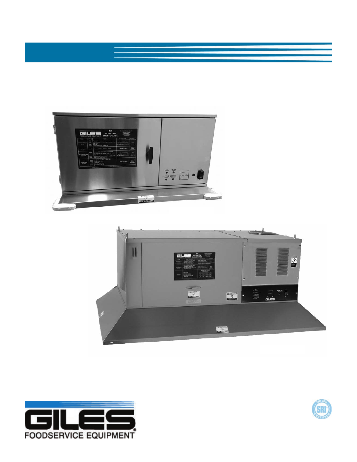
PO-VH & OVH-10
Model: OVH-10
Model: PO-VH
Giles Enterprises, Inc.
ISO 9001 Registered Company • Committed to Quality
2750 Gunter Park Drive West • Montgomery, AL 36109 USA
Phone: 334.272.1457 • Fax: 334. 239-4117 • www.gfse.com
Service Hotline (Toll Free): 800.554.4537
Form No. 60203 (Rel. Date: 02/2001) (Rev: 02/2016, Rev. F)
(USA & Canada Only)

LIMITED WARRANTY
• Subject to the terms and conditions of this Limited Warranty as herein stated, all Giles Enterprises,
Inc., Foodservice Equipment and parts purchased new from an authorized Giles Enterprises, Inc.,
representative are warranted as to defects in material or workmanship for a period of 24 months
from the date of installation, provided, however, that with regard to labor costs in connection with
this warranty, see below. All installations must be made by a qualified installing agency in accordance with all applicable codes and/or regulations in the jurisdiction in which installed. Limited warranty coverage is extended to the original owner only and is void if the unit is resold.
• During the Limited Warranty period, Giles Enterprises, Inc. will replace or recondition, at its factory,
any part or parts of this unit which Giles Enterprises, Inc. inspectors judge defective, provided the
unit has been subjected to normal usage, properly installed, operated and serviced. This Limited
Warranty does not cover cosmetic damage, and damage due to acts of God, accident, misuse, alteration, negligence, abuse of the Giles Foodservice Equipment or the use of unorthodox repair methods. All parts replaced under this Limited Warranty carry only the unexpired term of this Limited
Warranty. Limited Warranty service may be furnished only by an authorized Giles Enterprises, Inc.,
representative.
• Failure to use Giles OEM parts and OEM replacement filters may void the factory warranty.
• If Limited Warranty service is requested, Giles Enterprises, Inc., will send factory-authorized service representatives to repair, recondition, replace or inspect units of its manufacture with such labor
being rendered without cost to owner for 24 months from the date of installation. Otherwise, service, including labor and transportation charges or other expenses, in connection with the removal or
installation of any part or parts supplied under this Limited Warranty, are specified on the original
sales contract between the purchaser and the authorized Giles Enterprises, Inc., representative.
• Giles Enterprises, Inc. reserves the right to change or improve its equipment and parts in any way
without obligation to alter such equipment or parts previously manufactured.
• Giles Enterprises, Inc. makes no further warranties, express or implied including implied warranties
of merchantability or fitness for a particular purpose, and has no other obligation or liability not
specifically stated herein.
• Repair or replacement as provided under this limited warranty is the exclusive remedy. Giles
Enterprises, Inc., shall not be liable for any incidental or consequential damages for breach of any
express or implied warranty on this product, except to the extent prohibited by applicable law. Any
implied warranty of merchantability or fitness for a particular purpose on this product is limited in
duration to the duration of this limited warranty.
• Used Giles Enterprises, Inc., Foodservice Equipment or parts or Giles Enterprises, Inc., Foodservice
Equipment or parts not purchased from an authorized Giles Enterprises, Inc., representative, carry
no warranties, express or implied.


Model: PO-VH & OVH-10Table Of Contents
Safety v
Safety Overview. . . . . . . . . . . . . . . . . . . . . . . . . . . . . . . . . . . . . . . . . . . . . . . . . . . . . . . . . . . . . . . . . . . . . . . . . . . . . . . . . v
Specific Safety Precautions . . . . . . . . . . . . . . . . . . . . . . . . . . . . . . . . . . . . . . . . . . . . . . . . . . . . . . . . . . . . . . . . . . . . . . . vi
1. Introduction . . . . . . . . . . . . . . . . . . . . . . . . . . . . . . . . . . . . . . . . . . . . . . . . . . . . . 1
1.1. Construction . . . . . . . . . . . . . . . . . . . . . . . . . . . . . . . . . . . . . . . . . . . . . . . . . . . . . . . . . . . . . . . . . . . . . . . . . 1
1.2. Standard Features. . . . . . . . . . . . . . . . . . . . . . . . . . . . . . . . . . . . . . . . . . . . . . . . . . . . . . . . . . . . . . . . . . . . . 1
1.3. Optional Features. . . . . . . . . . . . . . . . . . . . . . . . . . . . . . . . . . . . . . . . . . . . . . . . . . . . . . . . . . . . . . . . . . . . . 1
1.4. Specifications . . . . . . . . . . . . . . . . . . . . . . . . . . . . . . . . . . . . . . . . . . . . . . . . . . . . . . . . . . . . . . . . . . . . . . . . 2
1.4.1. Overall Dimensions for PO-VH (UCA) . . . . . . . . . . . . . . . . . . . . . . . . . . . . . . . . . . . . . . . . . . . . . . . . . . . . . 2
1.4.2. Overall Dimensions for OVH-10 (UCM) . . . . . . . . . . . . . . . . . . . . . . . . . . . . . . . . . . . . . . . . . . . . . . . . . . . 3
1.4.3. Regulatory Listings . . . . . . . . . . . . . . . . . . . . . . . . . . . . . . . . . . . . . . . . . . . . . . . . . . . . . . . . . . . . . . . . . . . . 4
1.4.4. Hood Weights . . . . . . . . . . . . . . . . . . . . . . . . . . . . . . . . . . . . . . . . . . . . . . . . . . . . . . . . . . . . . . . . . . . . . . . . 4
1.4.5. Appliance Restrictions fo PO-VH Hood . . . . . . . . . . . . . . . . . . . . . . . . . . . . . . . . . . . . . . . . . . . . . . . . . . . . 4
1.4.6. Appliance Restrictions for OVH-10 Hood . . . . . . . . . . . . . . . . . . . . . . . . . . . . . . . . . . . . . . . . . . . . . . . . . . 4
2. Installation . . . . . . . . . . . . . . . . . . . . . . . . . . . . . . . . . . . . . . . . . . . . . . . . . . . . . . 5
2.1. Location. . . . . . . . . . . . . . . . . . . . . . . . . . . . . . . . . . . . . . . . . . . . . . . . . . . . . . . . . . . . . . . . . . . . . . . . . . . . . 5
2.2. Unpacking . . . . . . . . . . . . . . . . . . . . . . . . . . . . . . . . . . . . . . . . . . . . . . . . . . . . . . . . . . . . . . . . . . . . . . . . . . . 6
2.3. Hood Electrical Requirements . . . . . . . . . . . . . . . . . . . . . . . . . . . . . . . . . . . . . . . . . . . . . . . . . . . . . . . . . . . 7
2.4. Electrical Connections . . . . . . . . . . . . . . . . . . . . . . . . . . . . . . . . . . . . . . . . . . . . . . . . . . . . . . . . . . . . . . . . . 8
2.4.1 Routing Power Wires . . . . . . . . . . . . . . . . . . . . . . . . . . . . . . . . . . . . . . . . . . . . . . . . . . . . . . . . . . . . . . . . . . 8
2.4.2 Electrical Connections for Installation over a 208/240V Appliance . . . . . . . . . . . . . . . . . . . . . . . . . . . . . 9
2.4.3 Electrical Connections for Installation over a 480V Appliance. . . . . . . . . . . . . . . . . . . . . . . . . . . . . . . . . 9
2.5. Bumper guard Installation (PO-VH only) . . . . . . . . . . . . . . . . . . . . . . . . . . . . . . . . . . . . . . . . . . . . . . . . . 10
2.6. Fire Suppression System . . . . . . . . . . . . . . . . . . . . . . . . . . . . . . . . . . . . . . . . . . . . . . . . . . . . . . . . . . . . . . 11
2.6.1. General Installation - Hood with Fire Suppression Option . . . . . . . . . . . . . . . . . . . . . . . . . . . . . . . . . . . 11
3. Overview. . . . . . . . . . . . . . . . . . . . . . . . . . . . . . . . . . . . . . . . . . . . . . . . . . . . . . . 13
3.1. Control Panel: PO-VH . . . . . . . . . . . . . . . . . . . . . . . . . . . . . . . . . . . . . . . . . . . . . . . . . . . . . . . . . . . . . . . . 14
3.1.1. Control Panel: OVH-10 with E.A.C. Cleaning Timer . . . . . . . . . . . . . . . . . . . . . . . . . . . . . . . . . . . . . . . . 16
3.2. Filter Chamber and Exhaust . . . . . . . . . . . . . . . . . . . . . . . . . . . . . . . . . . . . . . . . . . . . . . . . . . . . . . . . . . . 18
3.3. Accessories (Included) . . . . . . . . . . . . . . . . . . . . . . . . . . . . . . . . . . . . . . . . . . . . . . . . . . . . . . . . . . . . . . . . 20
4. Operation & Filter Maintenance. . . . . . . . . . . . . . . . . . . . . . . . . . . . . . . . . . . . 23
4.1. Hood Operation . . . . . . . . . . . . . . . . . . . . . . . . . . . . . . . . . . . . . . . . . . . . . . . . . . . . . . . . . . . . . . . . . . . . . 23
4.2. Filters, Filter Maintenance and Filter Alarms . . . . . . . . . . . . . . . . . . . . . . . . . . . . . . . . . . . . . . . . . . . . . 23
4.2.1. Ventless Hood Filter Table. . . . . . . . . . . . . . . . . . . . . . . . . . . . . . . . . . . . . . . . . . . . . . . . . . . . . . . . . . . . . 23
4.2.2. Accessing the Filter Chamber . . . . . . . . . . . . . . . . . . . . . . . . . . . . . . . . . . . . . . . . . . . . . . . . . . . . . . . . . . 24
4.2.3. Hood Filter Management . . . . . . . . . . . . . . . . . . . . . . . . . . . . . . . . . . . . . . . . . . . . . . . . . . . . . . . . . . . . . 26
4.2.3.1. Baffle Filter Removal & Installation . . . . . . . . . . . . . . . . . . . . . . . . . . . . . . . . . . . . . . . . . . . . . . . . . . . . . 26
4.2.3.2. E.A.C. Filter Cell Removal & Installation. . . . . . . . . . . . . . . . . . . . . . . . . . . . . . . . . . . . . . . . . . . . . . . . . . 27
4.2.3.3. Charcoal Filter Removal & Installation . . . . . . . . . . . . . . . . . . . . . . . . . . . . . . . . . . . . . . . . . . . . . . . . . . . 28
iii

Model: PO-VH & OVH-10 Table Of Contents
4.2.4. Hood Filter Alarms . . . . . . . . . . . . . . . . . . . . . . . . . . . . . . . . . . . . . . . . . . . . . . . . . . . . . . . . . . . . . . . . . . . 29
4.2.4.1. Charcoal or Baffle Filter Missing . . . . . . . . . . . . . . . . . . . . . . . . . . . . . . . . . . . . . . . . . . . . . . . . . . . . . . . . 29
4.2.4.2. Charcoal or Baffle Filter Clogged. . . . . . . . . . . . . . . . . . . . . . . . . . . . . . . . . . . . . . . . . . . . . . . . . . . . . . . . 29
4.2.4.3. E.A.C. Filter Status & Alarm. . . . . . . . . . . . . . . . . . . . . . . . . . . . . . . . . . . . . . . . . . . . . . . . . . . . . . . . . . . . 30
4.2.5. Filter Cleaning & Maintenance . . . . . . . . . . . . . . . . . . . . . . . . . . . . . . . . . . . . . . . . . . . . . . . . . . . . . . . . . 31
4.2.5.1. Baffle Filter Cleaning . . . . . . . . . . . . . . . . . . . . . . . . . . . . . . . . . . . . . . . . . . . . . . . . . . . . . . . . . . . . . . . . . 31
4.2.5.2. E.A.C. Filter Cell Cleaning. . . . . . . . . . . . . . . . . . . . . . . . . . . . . . . . . . . . . . . . . . . . . . . . . . . . . . . . . . . . . . 31
4.2.5.3 E.A.C. Filter Cleaning Timer (OVH-10 Only) . . . . . . . . . . . . . . . . . . . . . . . . . . . . . . . . . . . . . . . . . . . . . . . 32
4.2.5.4. Charcoal Filter Maintenance . . . . . . . . . . . . . . . . . . . . . . . . . . . . . . . . . . . . . . . . . . . . . . . . . . . . . . . . . . . 33
5. Hood Cleaning and Maintenance . . . . . . . . . . . . . . . . . . . . . . . . . . . . . . . . . . . 34
5.1. Hood Cleaning . . . . . . . . . . . . . . . . . . . . . . . . . . . . . . . . . . . . . . . . . . . . . . . . . . . . . . . . . . . . . . . . . . . . . . 34
6. Troubleshooting . . . . . . . . . . . . . . . . . . . . . . . . . . . . . . . . . . . . . . . . . . . . . . . . . 35
6-1. Troubleshooting Procedures . . . . . . . . . . . . . . . . . . . . . . . . . . . . . . . . . . . . . . . . . . . . . . . . . . . . . . . . . . . 35
7. Parts List . . . . . . . . . . . . . . . . . . . . . . . . . . . . . . . . . . . . . . . . . . . . . . . . . . . . . . . 37
7.1. Parts Ordering and Service Information . . . . . . . . . . . . . . . . . . . . . . . . . . . . . . . . . . . . . . . . . . . . . . . . . . 37
7.2. Control Panel: PO-VH . . . . . . . . . . . . . . . . . . . . . . . . . . . . . . . . . . . . . . . . . . . . . . . . . . . . . . . . . . . . . . . . 38
7.3. Control Panel: OVH-10 . . . . . . . . . . . . . . . . . . . . . . . . . . . . . . . . . . . . . . . . . . . . . . . . . . . . . . . . . . . . . . . 40
7.4. Fan Compartment: PO-VH . . . . . . . . . . . . . . . . . . . . . . . . . . . . . . . . . . . . . . . . . . . . . . . . . . . . . . . . . . . . 42
7.5. Fan Compartment: OVH-10 . . . . . . . . . . . . . . . . . . . . . . . . . . . . . . . . . . . . . . . . . . . . . . . . . . . . . . . . . . . 44
7.6. Filter Compartment: PO-VH . . . . . . . . . . . . . . . . . . . . . . . . . . . . . . . . . . . . . . . . . . . . . . . . . . . . . . . . . . . 46
7.7 Filter Compartment: OVH-10 . . . . . . . . . . . . . . . . . . . . . . . . . . . . . . . . . . . . . . . . . . . . . . . . . . . . . . . . . . 48
iv
Model: PO-VH & OVH-10Safety
Safety
Safety Overview
The instructions presented in this manual have been prepared to aid you in learning proper procedures for installing,
operating and servicing the unit.
Throughout this manual, safety precautions are identified by use of safety alert symbols and three key words:
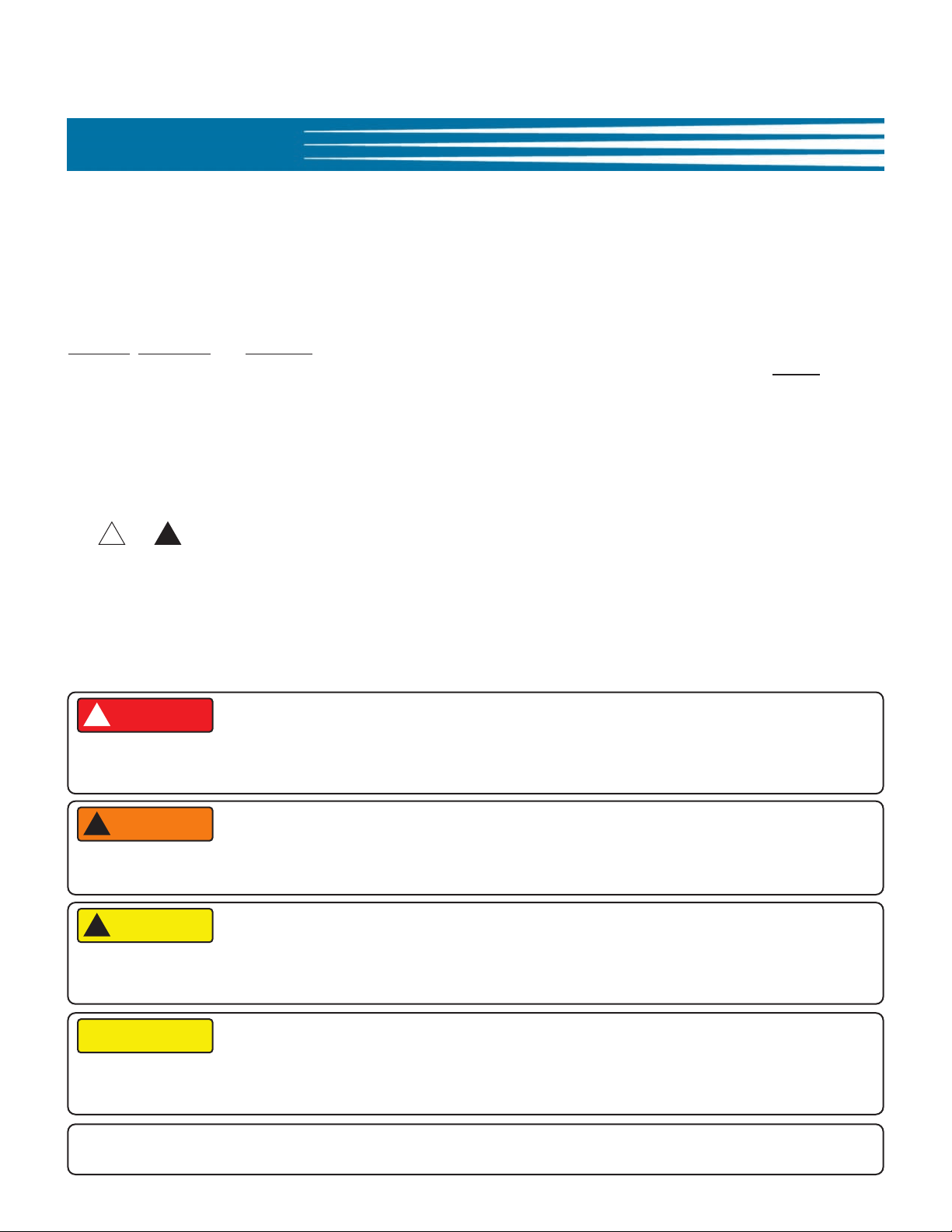
DANGER
applies. Suggested, recommended, or other noteworthy information is identified through the use of NOTES
Additionally, the following words are used to convey specific meaning or to add emphasis:
Safety Alert Symbols
Used in conjunction with key words (DANGER, WARNING, or CAUTION) that immediately precede precautionary
measures to alert you of potential personal injury hazards that may arise. Obey all safety information following
these symbols to avoid possible injury, or even death. Failure to adhere to safety precautions identified by the
safety alert symbols may also void the factory warranty.
, WARNING and CAUTION. Safety alert information will precede the step, or series of steps, to which it
.
Shall: understood to be mandatory.
Should: understood to be advisory.
May: understood to be permissive.
Will: indicates potential for occurrence of a future event or condition.
!!
or
DANGER
!
Indicates an imminently hazardous situation which, if not avoided, will result in serious injury or possible death.
Use of this is limited to the most extreme situations.
WARNING
!
Indicates a potentially hazardous situation which, if not avoided, could result in serious injury or possible death.
CAUTION
!
Indicates a potentially hazardous situation which, if not avoided, may result in moderate to minor injuries. Also
used to alert operator to unsafe practices.
CAUTION
When used without the safety alert symbol, CAUTION indicates a potentially hazardous situation which, if not
avoided, may result in equipment or property damage, and could void the factory warranty.
NOTE:
Identifies suggested, recommended, or other noteworthy information.
v
Model: PO-VH & OVH-10 Safety
Specific Safety Precautions
For safety, please observe the following precautions when operating or servicing Model PO-VH or OVH-10 Ventless
Recirculating Hoods. Reading and understanding the following important safety information will help avoid personal
injury and/or damage to equipment or property.
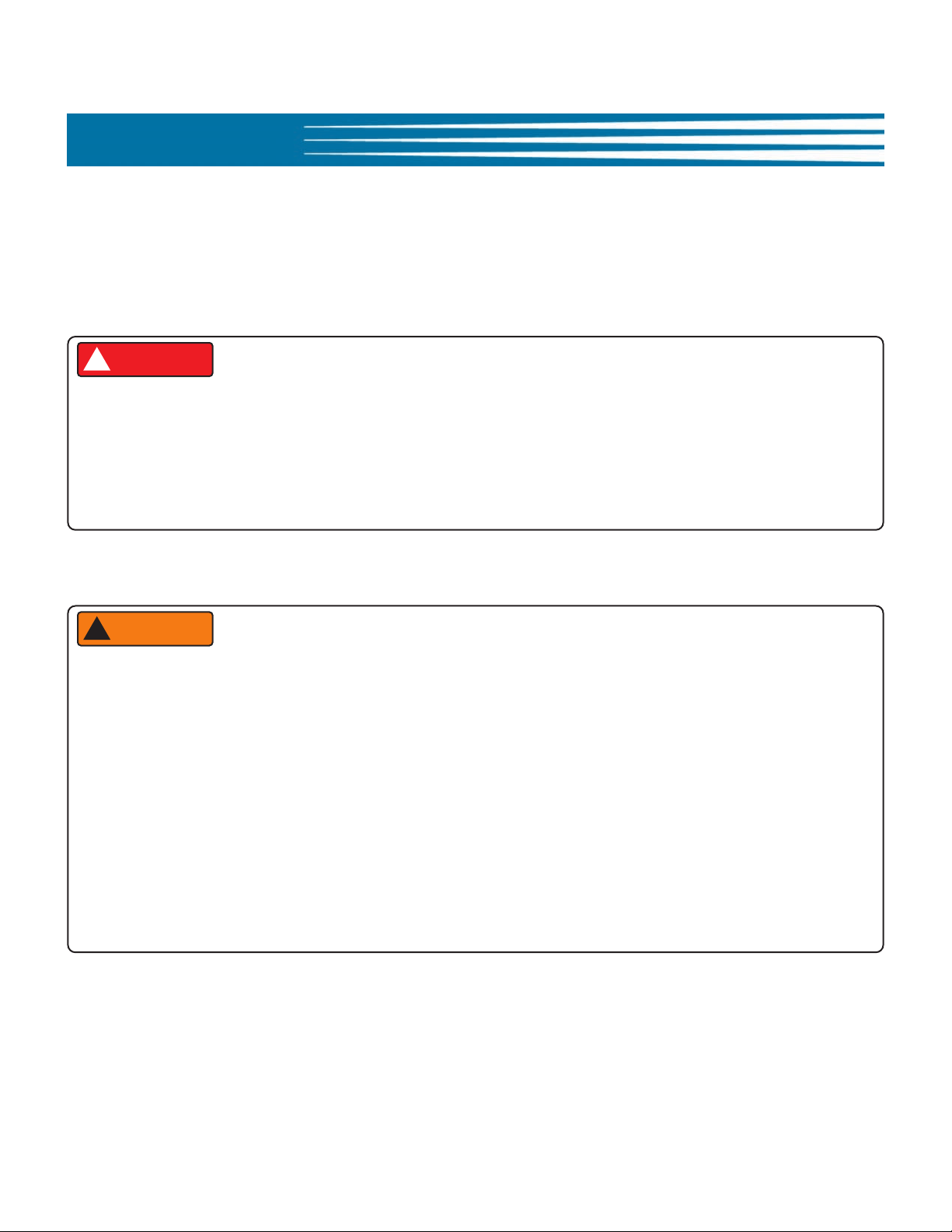
DANGER
!
• Always disconnect the source of main hood power before removing any electrical Access Panel or Cover.
• Failure to have the Power switch in the OFF position during servicing or when replacing filters, could result in
equipment damage, electrical shock and/or serious personal injury.
• Failure to comply with these DANGER notices will result in serious injury or possible death, equipment or
property damage, and could void the warranty.
WARNING
!
• DO NOT use or store flammable liquids, or materials which may produce flammable vapors, in the vicinity of this
or any other appliance!
• Consult a qualified electrician to ensure all electrical specifications have been met and the unit is properly
grounded in accordance with applicable codes.
• Before installing or servicing this equipment, read the contents of this manual thoroughly. Secure the hood
mounting instructions, read and fully understand prior to beginning installation.
• Improper installation, adjustment, alteration, service or maintenance could result in serious injury or possible
death, equipment or property damage, and could void the warranty.
• Failure to comply with these WARNING notices could result in serious injury or possible death, and equipment or
property damage.
vi
Model: PO-VH & OVH-10Safety
CAUTION
!
• Maintain a minimum clearance of 12” (304.8mm) between the hood exhaust outlet and ceiling, or any overhead
obstruction. Giles recommends an 18” (457.2mm) clearance for best performance. Some Hood models are
equipped with an Exhaust Air Diverter attached to the exhaust outlet. In that case there is no
requirement with respect to ceiling clearance.
• Exercise care when lifting, handling and removing the unit from the shipping skid. Refer to Section 1.4.4, Hood
Weights
• DO NOT operate the unit unless you fully understand its components and their intended function.
• Handle the Electronic Air Cleaner (EAC) cell carefully. DO NOT bend the collection plates (fins) or break any of
the ionizer wires. Doing so will significantly reduce the performance of the EAC and will eventually cause power
to the appliance beneath the Hood to be shutdown.
•
Failure to comply with these CAUTION notices may result in moderate to minor injury, equipment or
property damage, and could void the warranty.
minimum
CAUTION
• The Control Panel components are impact-sensitive. Exercise care to avoid damage and maintain proper
operation.
• DO NOT attempt to dry the E.A.C. Cell after cleaning by installing it and running the hood or by running the
appliance below the hood to generate heat for drying. This could potentially damage the EAC Power Supply
causing improper operation and voiding the warranty. NEVER PLACE A WET E.A.C. CELL INTO THE HOOD.
• When cleaning the Hood.
•• DO NOT steam clean or use any type pressure washer.
•• DO NOT use products containing chlorine or other caustic chemicals.
•• DO NOT use abrasive products, steel wool or scouring pads.
• Failure to comply with these CAUTION notices may result in equipment or property damage and could void the
warranty.
vii
Model: PO-VH & OVH-10 Safety
NOTE:
• If after unpacking the unit and its accessories, damage is observed, immediately and thoroughly inspect the Hood
and its accessories. Notify the freight company of any damages. Generally, negotiating freight damage claims
shall be the responsibility of the Customer.
• To aid with electrical installation, a wiring diagram has been included with the unit.
• Comply with all appropriate state and/or local heath regulations regarding cleaning and sanitation of any
foodservice equipment.
• To clean difficult surface areas, having excessive build-up of grease residue, Giles recommends using a mild, bio-
degradable, non-toxic degreaser such as Simple Green
• Ensure that the unit is electrically grounded and installed in accordance with local codes, or in the absence of
local code, in accordance with the prevailing National Electrical Code ANSI/NFPA 70.
or Clear Magic.
viii

Model: PO-VH & OVH-10Introduction
1. Introduction
Thank you purchasing a new Giles Ventless Recirculating Hood System (PO-VH or OVH-10) manufactured by Giles
Enterprises, Inc., Montgomery, Alabama, USA. Proper care and maintenance of this unit will ensure years of trouble-free
service.
To help protect your investment in this equipment, we recommend taking a few moments to familiarize yourself with the
installation, operational, cleaning and maintenance procedures described in this manual. Please secure and retain the
installation instructions; thoroughly understand them before beginning installation. Adherence to these recommended
procedures minimizes the potential for costly "downtime" and equipment repairs. Please retain this manual for future
reference.
1.1 Construction
Giles’ Ventless Hood Systems are constructed of stainless and aluminized sheet steel.
1.2 Standard Features
Control Panel
• Indicator lights show the status of various Hood systems: Electronic Air Cleaner (EAC), appliance power, filter missing
warning, and clogged filter warning.
3-Stage Filter System
• Baffle Filter: Collects and removes large grease particulate from the air stream.
• Electronic Air Cleaner (EAC): Captures & collects smoke and fine grease particulate from the air stream. A HEPA Filter
option is also available at time of purchase.
• Charcoal Filter: Helps to eliminate cooking aromas from the recirculated air.
Multiple Mounting Options
• For a universal application, the Hood may be suspended from the ceiling, allowing accommodation of practically any
listed and approved appliance.
• PO-VH & OVH-10 Hoods are designed to accommodate customized skirts, allowing for direct-mounting onto a wide
variety of popular oven styles.
1.3 Optional Features
• Interlocking Start System (ILS): “Push to Start” feature prevents the Hood and the served Appliance from restarting
when power is restored after a power interruption until it is attended by an operator. This feature may be required by
local building codes. Please check with your local code officials to see if this system is required.
• Fire Suppression Plumbing:
system. Includes piping, discharge nozzles, fusible link brackets, and fusible link cable conduit. Purchase, installation
and commissioning of the actual fire extinguishing system is the Customer’s responsibility and is not included with
the purchase of this optional feature.
• Power Plug & Receptacle:
receptacle is provided internal to the Hood for connecting the served appliance, making the unit completely “plug &
play”.
The Hood can be factory pre-plumbed for connection to an approved fire extinguishing
The Hood can be equipped with a power cord for ease of installation. An interlocked
1
Model: PO-VH & OVH-10 Introduction
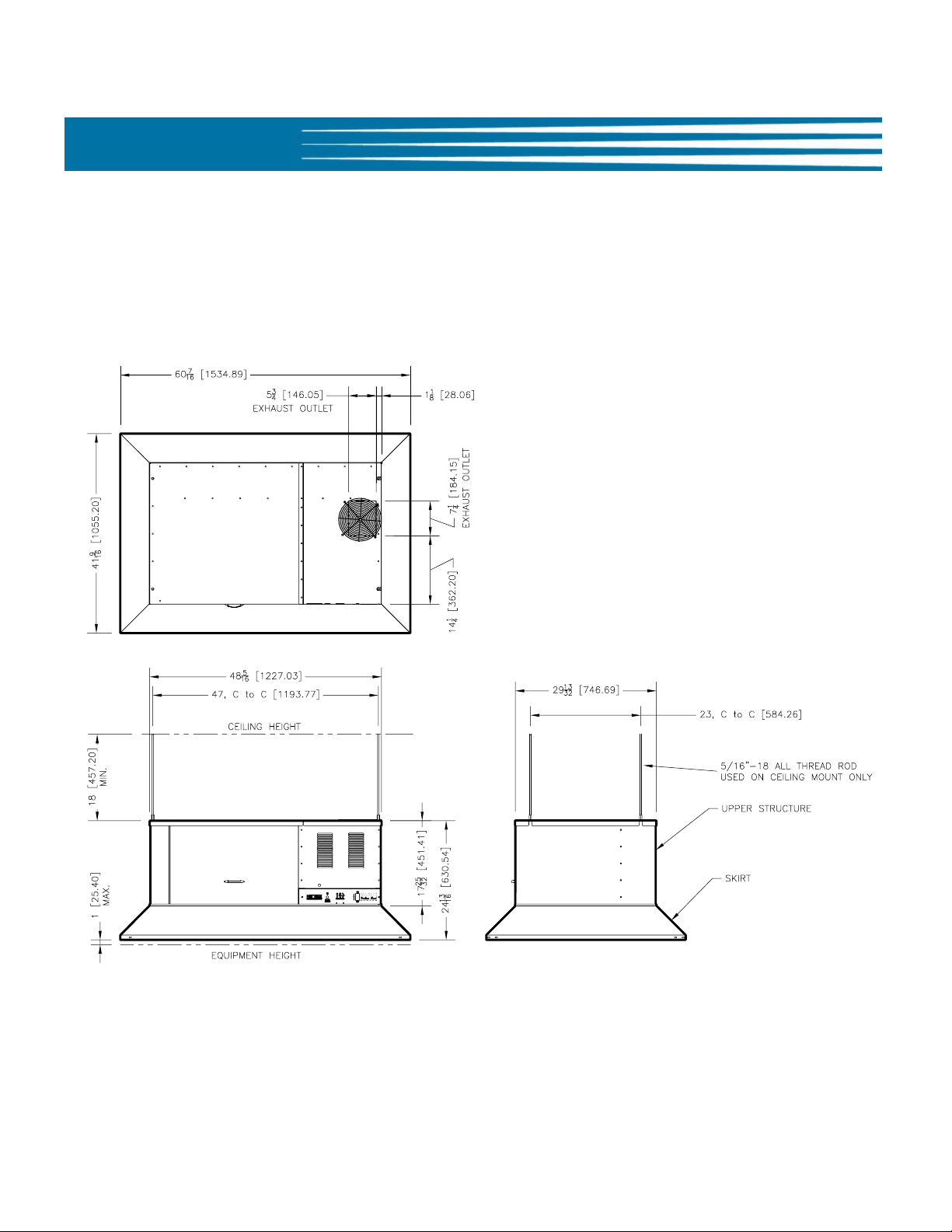
1.4 Specifications
1.4.1 Overall Dimensions ... PO-VH (UCM model)
2
35 15/16
913.08
7
177.81
21 15/16
557
24 7/16
620.73
30 1/16
763.43
17 1/4
438.15
C TO C
28 7/8
733.91
C TO C
30 3/8
771.09
8 1/16
205.21
40 1/2
1029.16
(4) 5/16-18 COUPLING NUTS
FOR CEILING MOUNTING
OPTIONAL EXTINGUISHER PIPING AND
FUSIBLE LINK SYSTEM FOR HOOD
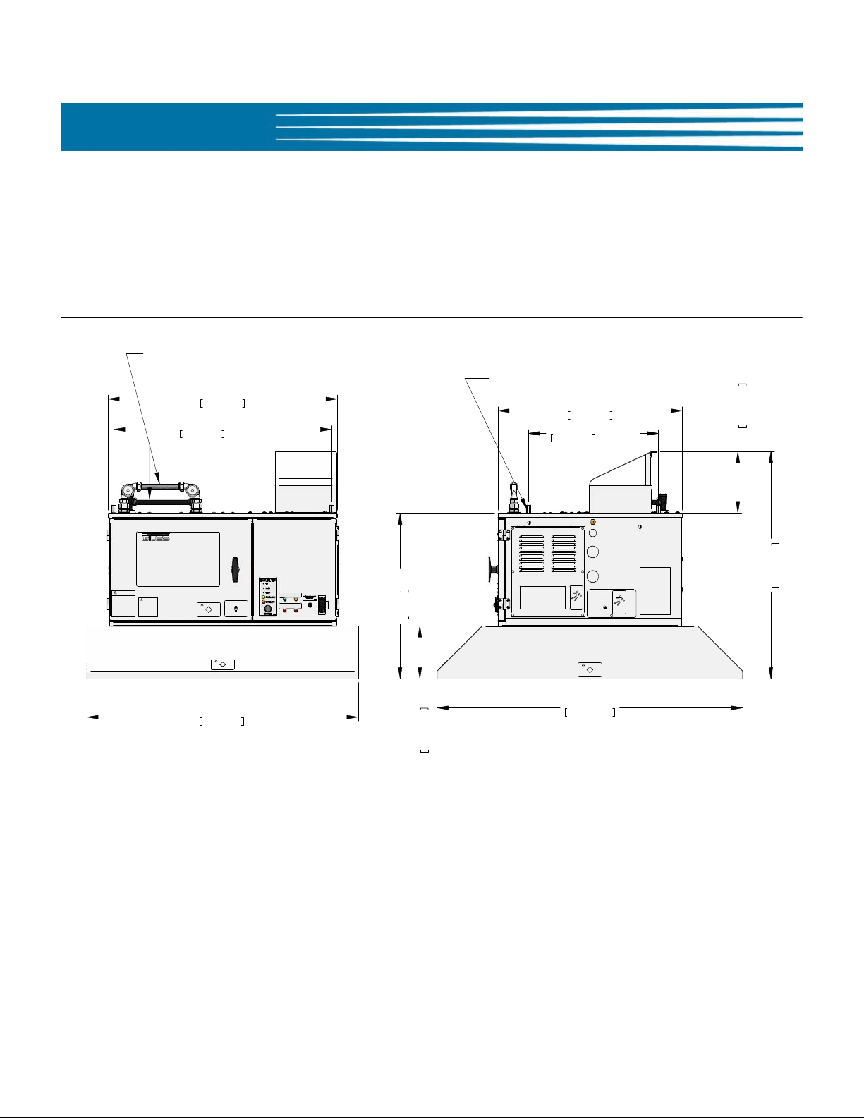
1.4.2 Overall Dimensions ... OVH-10 (UCM model)
Model: PO-VH & OVH-10Introduction
3
Model: PO-VH & OVH-10 Introduction
1.4.3 Regulatory Listings
1.4.4 Hood Weights*
Hood Crated Weight Uncrated Weight
PO-VH 337 lbs [152.8 kg] 221 lbs [100.2 kg]
OVH-10 221 lbs [100.2 kg] 130 lbs [58.9 kg]
* Weights shown are typical; actual weight may vary depending upon the Skirt design and selected options.
1.4.5 Appliance Restrictions for POVH Hood
Unit Type Max. Total Input, kW Max. Clearance
Electric Oven
(POVH ONLY - ovens may be double stacked
in certain applications)
Electric Rotisserie 6 6” [153 mm] to door top
50 30” [762 mm] to cooking surface
1.4.6 Appliance Restrictions for OVH-10 Hood
Unit Type Max. Total Input, Max. Clearance
Electric Oven 11.5 30” [762mm] to cooking surface
Electric Rotisserie 6 6” [153] to door top
WARNING
!
PO-VH & OVH-10 Recirculating Ventless Hoods are not approved for use with gas heated appliances.
4

Model: PO-VH & OVH-10Installation
2. Installation
This section summarizes the procedures necessary to install your new PO-VH or OVH-10. Before installing this
equipment, please thoroughly read the contents of this manual and any accompanying installation instructions.
Following these procedures and instructions will help to ensure a safe and proper installation.
2.1 Location
CAUTION
!
• DO NOT ALTER, ADD ATTACHMENTS OR OTHERWISE MODIFY THIS EQUIPMENT.
NOTE:
• For some installations, consultation with a HVAC contractor may be required to confirm that proper room air
exchange is occurring, and that the heat load capability of current air conditioning systems is sufficient.
• Exhaust ventilation is recommended for areas in which recirculating hoods are being operated. Giles
recommends at least 50 CFM airflow per linear foot of hood space. This amount could vary based on local codes
and site-specific installation requirements.
• The sound level produced by the hood when operating is approximately 65 dB’s.
1. When using the ceiling mount method of installation, ensure that the overhead structure is sufficient to
support the weight load of the Hood.
2. Once final installation and positioning of the unit is complete, there must be no obstruction of the Hood’s
exhaust air outlet. A minimum clearance of 12” (304.8mm)
overhead obstructions, and the exhaust outlet on top of the unit. Giles recommends an 18” (457.2mm)
clearance for best hood performance.
Some Hood models feature an Air Diverter on the exhaust outlet. In that case there is no
requirement with respect to ceiling clearance, as exhaust is diverted to the sides and rear.
must be maintained between the ceiling, or
minimum
5
Model: PO-VH & OVH-10 Installation
2.2 Unpacking
The unit is shipped on a wooden skid, secured by high-tensile plastic strapping, and wrapped in machine-applied
stretch wrap. In some cases a corrugated sleeve or wooden framework may also be used to protect the unit.
Unpack the unit as follows:
1. Position the unit in an area that provides adequate space for unpacking.
2. Remove the plastic stretch wrap, strapping and other packaging materials as necessary.
3. Carefully remove any wooden supports and/or framework that might be attached to the skid.
4. Locate and secure the envelope containing Warranty Card, Operation Manual, Mounting Instructions and any
other hardware provided for installation. In some cases, additional mounting components may be wrapped
separately and packed with the Hood (usually inside the Soak Tank) ... secure any such items and be certain they
are retained for later use.
5. Secure the stainless steel Soak Tank and set aside. Check inside the Tank, as additional components are often
packed inside. There will be no Soak Tank included with the unit if it is a HEPA Filter model Hood.
CAUTION
!
• Exercise care when lifting and handling the unit, please refer to Section 1.4.4, Hood Weights.
• Exercise care when removing and disposing of packaging materials.
• Failure to comply with these CAUTION notices may result in moderate to minor injury, equipment or property
damage, and could void the warranty.
NOTE:
• If there is evidence of damage to the unit, or any of the accompanying items, immediately and thoroughly inspect
the unit and all components. Notify the freight company of all damages. Generally, it is the responsibility of the
Customer to file and negotiate freight damage claims with freight companies.
6
Model: PO-VH & OVH-10Installation
2.3 Hood Electrical Specifications
WARNING
!
• Consult a qualified electrician to ensure that all electrical specifications have been met and that the unit is
properly wired and grounded.
•I
mproper installation, adjustment, alteration, service or maintenance could result in serious injury or possible
death, equipment or property damage, and could void the warranty.
Electrical Specifications (Hood Only)
Unit Voltage Hz Phase Watts Amps Breaker
OVH-10 208 60 1 433 2.1 10
OVH-10 240 60 1 433 1.8 10
PO-VH 208 60 1 920 4.4 10
PO-VH 240 60 1 920 3.8 10
PO-VH 220 50 1 920 4 10
NOTE:
• PO-VH & OVH-10 Hoods are designed to operate with either 208V or 240V supply power; the table above shows
amp draw for each voltage.
• Breaker sizes shown apply to Hood power only. Power to the served appliance is typically interlocked through
the hood’s circuitry such that the hood and appliance are powered through the same breaker. In such cases,
breaker size shall be determined by the combined electrical load of the hood and appliance.
7
Model: PO-VH & OVH-10 Installation
2.4 Electrical Connections
1. Confirm that appropriate circuit breakers are installed in the Main Breaker Panel. Refer to table in Section
2.3.
2. Connect appropriately size wiring to the Main Breaker. As applicable, allow enough wire length so the unit
may be moved for cleaning and servicing.
3. Remove the Hood’s Service Panel. Refer to Figure 2.4.1.
4. Route the power wires to the unit in accordance with all local building codes, as applicable.
5. If the Hood is to be installed above a 208/240V appliance connect appropriate incoming power wires to the
proper terminal blocks. Use appropriate strain relief connectors or conduit fittings (not provided) for routing
wiring through knock-out holes. Refer to Section 2.4.2 and the Label affixed to service panel.
If the Unit is to be installed above a 480V appliance, refer to Section, 2.4.3 and the Label affixed to the
service panel.
6. Reinstall Service Panel.
8. Turn ON main breaker.
9. Place the Hood Power Switch to the ON position. Hood with ILS option: Place Power Switch in ON position,
then press and hold Start Button for approximately 5 seconds to energize the Hood.
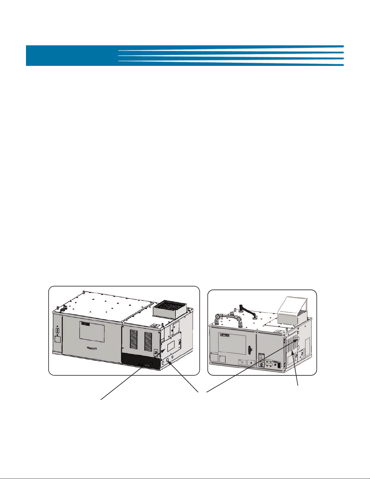
2.4.1 Routing Power Wires
POVH
OVH-10
NOTE: Skirt not shown
8
Service Panel
Service Panel
Hole Plugs - Openings for routing of
appropriate power cables. Use proper
fittings and strain reliefs, as needed (not
provided).
Model: PO-VH & OVH-10Installation
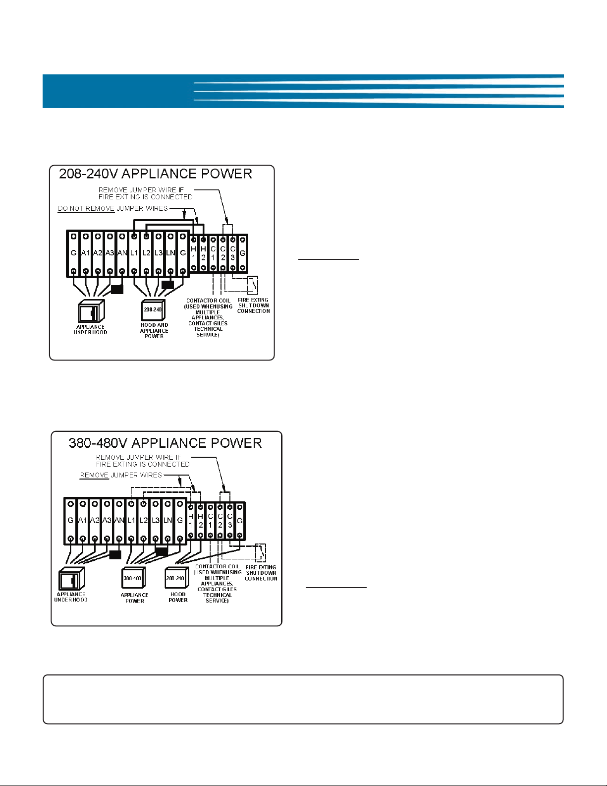
2.4.2 Electrical Connections for Installation over a 208/240V Appliance
• Connect incoming main power wires from breaker
panel to terminal blocks L1, L2, L3, G.
• Connect appliance power wires to terminal blocks A1,
A2, A3, G (outgoing power).
• Should there be any question as to proper connection
procedures call Giles’ Technical Service at
800.554.4537
• If hood is equipped with Fire Suppression System
option connect as directed.
• All materials and labor needed for electrical
installation are to be provided by the user.
.
2.4.3 Electrical Connections for Installation over a 480V Appliance
• Connect incoming main power wires (480V) from
breaker panel to terminal blocks L1, L2, L3, G.
• Connect wires from appliance power cord to terminal
blocks A1, A2, A3, G (outgoing power).
• Connect incoming low voltage (208-240V) power
wires to terminal blocks H1, H2, G
• Remove jumper wires from between L1-L2 and H1-
H2.
• Should there be any question as to proper connection
procedures call Giles’ Technical Service at
800.554.4537
• If hood is equipped with Fire Suppression System
option connect as directed.
• All materials and labor needed for electrical
installation are to be provided by the user.
.
NOTE: The Neutral Line terminal blocks (LN & AN) are not required for domestic installations. Adhere to all local
codes when installing this equipment. A certified electrician may be required for installation of this
equipment.
9
 Loading...