

Page 1
MANUALE STAZIONE DI SERVIZIO
XXXXXX IT- EN-FR-DE-ES-PT-NL-EL
MSS Nexus 300 i.e. E3 ( 2008)
Page 2

MANUALE
STAZIONE DI
SERVIZIO
MSS Nexus 300 i.e. E3 ( 2008)
The descriptions and illustrations given in this publication are not binding. While the basic specifications
as described and illustrated in this manual remain unchanged, PIAGGIO-GILERA reserves the right, at
any time and without being required to update this publication beforehand, to make any changes to
components, parts or accessories, which it considers necessary to improve the product or which are
required for manufacturing or construction reasons.
Not all versions/models shown in this publication are available in all countries. The availability of single
versions should be checked at the official Piaggio sales network.
"© Copyright 2007 - PIAGGIO & C. S.p.A. Pontedera. All rights reserved. Reproduction of this publication
in whole or in part is prohibited."
PIAGGIO & C. S.p.A. - After-Sales
V.le Rinaldo Piaggio, 23 - 56025 PONTEDERA (Pi)
Page 3

MANUALE STAZIONE DI
SERVIZIO
MSS Nexus 300 i.e. E3 ( 2008)
Questo manuale per stazioni di servizio è stato realizzato da Piaggio & C. Spa per essere utilizzato dalle
officine dei concessionari e sub-agenzie Piaggio-Gilera. Si presuppone che chi utilizza questa
pubblicazione per la manutenzione e la riparazione dei veicoli Piaggio, abbia una conoscenza base dei
principi della meccanica e dei procedimenti inerenti la tecnica della riparazione dei veicoli. Le variazioni
importanti nelle caratteristiche dei veicoli o nelle specifiche operazioni di riparazione verranno
comunicate attraverso aggiornamenti di questo manuale. Non si può comunque realizzare un lavoro
completamente soddisfacente se non si dispone degli impianti e delle attrezzature necessarie, ed è per
questo che vi invitiamo a consultare le pagine di questo manuale riguardanti l'attrezzatura specifica e il
catalogo degli attrezzi specifici.
N.B. Provides key information to make the procedure easier to understand and carry out.
CAUTION Refers to specific procedures to carry out for preventing damages to the vehicle.
WARNING Refers to specific procedures to carry out to prevent injuries to the repairer.
Personal safety Failure to completely observe these instructions will result in serious risk of personal
injury.
Safeguarding the environment Sections marked with this symbol indicate the correct use of the vehicle
to prevent damaging the environment.
Vehicle intactness The incomplete or non-observance of these regulations leads to the risk of serious
damage to the vehicle and sometimes even the invalidity of the guarantee.
Page 4

Page 5

INDEX OF TOPICS
CHARACTERISTICS CHAR
TOOLING TOOL
MAINTENANCE MAIN
TROUBLESHOOTING TROUBL
ELECTRICAL SYSTEM ELE SYS
ENGINE FROM VEHICLE ENG VE
ENGINE ENG
INJECTION INJEC
SUSPENSIONS SUSP
BRAKING SYSTEM BRAK SYS
COOLING SYSTEM COOL SYS
CHASSIS CHAS
PRE-DELIVERY PRE DE
TIME TIME
Page 6

INDEX OF TOPICS
CHARACTERISTICS CHAR
Page 7

This section describes the general specifications of the vehicle.
Rules
This section describes general safety rules for any maintenance operations performed on the vehicle.
Safety rules
- If work can only be done on the vehicle with the engine running, make sure that the premises are wellventilated, using special extractors if necessary; never let the engine run in an enclosed area. Exhaust
fumes are toxic.
- The battery electrolyte contains sulphuric acid. Protect your eyes, clothes and skin. Sulphuric acid is
highly corrosive; in the event of contact with your eyes or skin, rinse thoroughly with abundant water
and seek immediate medical attention.
- The battery produces hydrogen, a gas that can be highly explosive. Do not smoke and avoid sparks
or flames near the battery, especially when charging it.
- Fuel is highly flammable and it can be explosive given some conditions. Do not smoke in the working
area, and avoid naked flames or sparks.
- Clean the brake pads in a well-ventilated area, directing the jet of compressed air in such a way that
you do not breathe in the dust produced by the wear of the friction material. Even though the latter
contains no asbestos, inhaling dust is harmful.
Maintenance rules
- Use original PIAGGIO spare parts and lubricants recommended by the Manufacturer. Non-original or
non-conforming spares may damage the vehicle.
- Use only the appropriate tools designed for this vehicle.
- Always use new gaskets, sealing rings and split pins upon refitting.
- After removal, clean the components using non-flammable or low flash-point solvents. Lubricate all
the work surfaces, except tapered couplings, before refitting these parts.
- After refitting, make sure that all the components have been installed correctly and work properly.
- For removal, overhaul and refit operations use only tools with metric measures. Metric bolts, nuts and
screws are not interchangeable with coupling members with English sizes. Using unsuitable coupling
members and tools may damage the scooter.
- When carrying out maintenance operations on the vehicle that involve the electrical system, make
sure the electric connections have been made properly, particularly the ground and battery connections.
MSS Nexus 300 i.e. E3 ( 2008) Characteristics
CHAR - 7
Page 8

Vehicle identification
To read the chassis prefix, remove the lid «A» in
the helmet compartment.
The engine prefix «B» is stamped near the left
shock absorber lower support.
VEHICLE IDENTIFICATION
Specification
Desc./Quantity
Chassis prefix ZAPM35600123456789
Engine prefix M356M
Dimensions and mass
WEIGHTS AND DIMENSIONS
Specification
Desc./Quantity
Kerb weight 174 ± 5 kg
Maximum weight allowed 370 Kg
Characteristics MSS Nexus 300 i.e. E3 ( 2008)
CHAR - 8
Page 9

Engine
ENGINE TECHNICAL DATA
Specification
Desc./Quantity
Type Single-cylinder, 4-stroke
Cubic capacity 278 cm³
Bore x Stroke 75x63 mm
Compression ratio 11 ± 0.5 : 1
Idle speed 1700 ± 100 rpm
Timing system 4 valves, single overhead camshaft, chain-driven.
Valve clearance Inlet: 0.10 mm Outlet: 0.15 mm
Max. power 16.1 kW at 7,250 rpm
Max. torque 23 Nm at 6,000 rpm
Main drive Automatic expandable pulley variator with torque server, V-
belt, automatic self-ventilating centrifugal dry clutch
Final reduction
Gear reduction unit in oil bath.
Lubrication Engine lubrication with lobe pump (inside crankcase) controlled
by a chain with double filter: mesh and paper.
Cooling Forced-circulation coolant system.
Electric start-up Oil-coated freewheel and torque limiter.
Ignition Electronic inductive discharge ignition, high efficiency, with
separate HV coil.
Ignition advance α/N three-dimensional map managed by control unit
Spark plug NGK CR8EKB
Fuel supply Electronic injection with electric fuel pump
Fuel Unleaded petrol (95 RON)
Exhaust muffler absorption-type exhaust muffler with catalytic converter.
Emission regulations EURO 3
MSS Nexus 300 i.e. E3 ( 2008) Characteristics
CHAR - 9
Page 10

Transmission
TRANSMISSION
Specification Desc./Quantity
Main drive Automatic expandable pulley variator with torque server, V-
belt, automatic self-ventilating centrifugal dry clutch
Capacities
CAPACITY
Specification Desc./Quantity
Engine oil 1.3 l
Transmission oil 250 cm³
Cooling system fluid ~ 1.8 l
Fuel tank (reserve) approx.15.00 l (approx. 2.80 l)
Electrical system
ELECTRICAL COMPONENTS
Specification
Desc./Quantity
Start-up Electric
Ignition Electronic inductive discharge ignition, high efficiency, with
separate HV coil.
Ignition advance α/N three-dimensional map managed by control unit
Spark plug NGK CR8EKB
Battery 12V/14 Ah, sealed battery
Frame and suspensions
FRAME AND SUSPENSIONS
Specification
Desc./Quantity
Chassis Tubular and sheet steel.
Front suspension Hydraulic telescopic fork with Ø 35 mm stem
Rear suspension Two double-acting shock absorbers, adjustable to four posi-
tions at preloading.
Brakes
BRAKES
Specification
Desc./Quantity
Front brake Ø 260-mm disc brake with hydraulic control activated by han-
dlebar right-side lever.
Rear brake Ø 240-mm disc brake with hydraulic control activated by the
handlebar left-side lever.
Characteristics MSS Nexus 300 i.e. E3 ( 2008)
CHAR - 10
Page 11

Wheels and tyres
WHEELS AND TYRES
Specification Desc./Quantity
Wheel rim type Light alloy rims.
Front tyre Tubeless, 120/70 - 15'' 56P
Rear tyre Tubeless, 140/60 - 14'' 64P
Front rim 15'' x 3.00
Rear rim 14'' x 3.50
TYRE PRESSURE
Specification Desc./Quantity
Front tyre pressure (with passenger) 2.3 bar (2.3)
Rear tyre pressure (with passenger) 2.3 bar (2.5)
N.B.
CHECK AND ADJUST TYRE PRESSURE WITH TYRES AT AMBIENT TEMPERATURE. REGULATE PRESSURE ACCORDING TO THE WEIGHT OF THE RIDER AND ACCESSORIES
Tightening Torques
STEERING
Name
Torque in Nm
Steering tube upper ring nut 40 ÷ 45
Steering tube lower ring nut 14 ÷ 17
Handlebar fixing screw 50 ÷ 55
Fixing screws for handlebar control assembly U-bolts 7 ÷ 10
CHASSIS
Name
Torque in Nm
Centre stand bolt 25 ÷ 30
Centre stand bolt 32 ÷ 40
Engine and vehicle side swinging arm junction bolt 33 ÷ 41
Body shell - Swinging arm pin 76 ÷ 83
Screw fixing the silent-block support plate to the body 42 ÷ 52
Engine-swinging arm bolt 64 - 72
FRONT SUSPENSION
Name
Torque in Nm
Fork leg screw 6 ÷ 7
Front wheel axle 45 ÷ 50
Hydraulic rod fixing screw 25 ÷ 35*
Fork locking screws cap 15 ÷ 30
Stem support clamp tightening screws 20 ÷ 25
Recommended products
Loctite 243 Medium strength threadlock
Loctite 243 medium-strength threadlock
REAR SUSPENSION
Name
Torque in Nm
Upper shock absorber clamp 33 ÷ 41
Lower shock absorber clamp 33 ÷ 41
Shock absorber-crankcase attachment bracket 20 ÷ 25
Rear wheel axle 104 ÷ 126
Muffler arm clamping screws 27 ÷ 30
MSS Nexus 300 i.e. E3 ( 2008) Characteristics
CHAR - 11
Page 12

FRONT BRAKE
Name Torque in Nm
Screw tightening calliper to the support 24 ÷ 27
Pad fastening pin 19.6 ÷ 24.5
Calliper support plate - fork fixing screws 41 ÷ 51
Brake disc screws 8 ÷ 10
Brake fluid pump-hose fitting 16 ÷ 20
Fixing screws for handlebar control assembly U-bolts 7 ÷ 10
Recommended products
Loctite 243 Medium strength threadlock
Loctite 243 medium-strength threadlock
REAR BRAKE
Name Torque in Nm
Rear brake calliper fixing screws 20 ÷ 25
Engine- calliper support plate fixing screws 48 ÷ 52
Brake disc screws 8 ÷ 10
Screw tightening calliper to the support 24 ÷ 27
Pad fastening pin 19.6 ÷ 24.5
Circuit bleed calliper fitting 12 - 16
Recommended products
Loctite 243 Medium strength threadlock
Loctite 243 medium-strength threadlock
MUFFLER
Name
Torque in Nm
Muffler heat guard fixing screw 4 ÷ 5
Screw for fixing muffler to the support arm 20 ÷ 25
Lambda probe clamp on exhaust manifold 40 ÷ 50
Exhaust manifold-muffler joint clamp 12 ÷ 13
Manifold - muffler diaphragm tightening clamp 16 ÷ 18
LUBRICATION
Name
Torque in Nm
Hub oil drainage plug 15 ÷ 17
Oil filter on crankcase fitting 27 ÷ 33
Engine oil drainage plug/mesh filter 24 ÷ 30
Oil filter 4 ÷ 6
Oil pump cover screws 7 ÷ 9
Screws fixing oil pump to crankcase 5 - 6
Oil pump control crown screw 10 ÷ 14
Oil pump cover plate screws 4 ÷ 6
Oil sump screws 10 ÷ 14
Minimum oil pressure sensor 12 ÷ 14
CYLINDER HEAD
Name
Torque in Nm
Spark plug 12 ÷ 14
Head cover screws 6 ÷ 7
Nuts fixing head to cylinder 7±1 + 10±1 + 270°
Head fixing side screws 11 ÷ 12
Starter ground screw 7 ÷ 8.5
Tappet set screw lock nut 6 ÷ 8
Inlet manifold screws 11 ÷ 13
Timing chain tensioner slider screw 10 ÷ 14
Starter ground support screw 11 ÷ 15
Timing chain tensioner support screw 11 ÷ 13
Timing chain tensioner central screw 5 - 6
Characteristics MSS Nexus 300 i.e. E3 ( 2008)
CHAR - 12
Page 13

Name Torque in Nm
Camshaft retention plate screw 4 ÷ 6
TRANSMISSION
Name Torque in Nm
Belt support roller screw 11 ÷ 13
Clutch unit nut on driven pulley 45 ÷ 50
Drive pulley nut 75 ÷ 83
Transmission cover screws 11 ÷ 13
Driven pulley shaft nut 54 ÷ 60
Rear hub cap screws 24 ÷ 27
FLYWHEEL
Name Torque in Nm
Flywheel cover screw 11 ÷ 13
Stator assembly screws 3 - 4 (Apply LOCTITE 242 medium-strength threadlock)
Flywheel nut 94 ÷ 102
Pick-Up clamping screws 3 ÷ 4
Screw fixing freewheel to flywheel 13 ÷ 15
CRANKCASE AND CRANKSHAFT
Name Torque in Nm
Internal engine crankcase bulkhead (transmission-side half
shaft) screws
4 ÷ 6
Engine-crankcase coupling screws 11 ÷ 13
Starter motor screws 11 ÷ 13
Crankcase timing cover screws 3.5 - 4.5 (Apply LOCTITE 242 medium-strength threadlock)
COOLING
Name
Torque in Nm
Water pump rotor cover 3 ÷ 4
Thermostat cover screws 3 ÷ 4
Bleed screw 3
Overhaul data
Assembly clearances
MSS Nexus 300 i.e. E3 ( 2008) Characteristics
CHAR - 13
Page 14

Cylinder - piston assy.
CYLINDER - PISTON
Specification
Desc./Quantity
Plunger diameter 74.967 +0.014 -0.014 mm
Cylinder diameter 75 +0.038 +0.01 mm
COUPLING CATEGORIES
Name
Initials Cylinder Piston Play on fitting
cylinder-piston M 75.01 ÷ 75.017 74.953 ÷ 74.960 0.050 ÷ 0.064
cylinder-piston N 75.017 ÷ 75.024 74.960 ÷ 74.967 0.050 ÷ 0.064
cylinder-piston O 75.024 ÷ 75.031 74.967 ÷ 74.974 0.050 ÷ 0.064
cylinder-piston P 75.031 ÷ 75.038 74.974 ÷ 74.981 0.050 ÷ 0.064
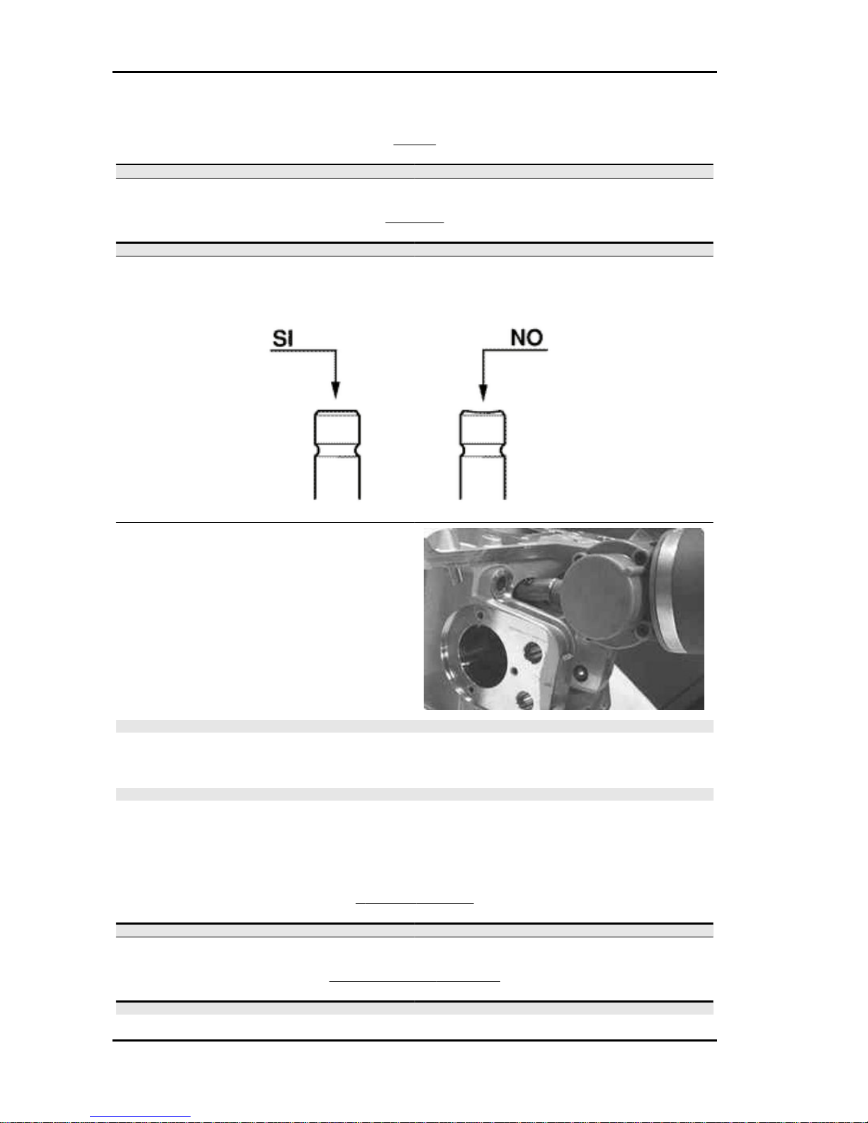
N.B.
THE PISTON MUST BE INSTALLED WITH THE ARROW FACING TOWARDS THE EXHAUST SIDE,
THE PISTON RINGS MUST BE INSTALLED WITH THE WORD «TOP» OR THE STAMPED MARK
FACING UPWARDS.
- Measure the outside diameter of the gudgeon
pin.
Characteristic
Pin outside diameter
16 +0 -0.004 mm
Characteristics MSS Nexus 300 i.e. E3 ( 2008)
CHAR - 14
Page 15

- Measure the diameter of the bearings on the piston.
Characteristic
Standard diameter
16 +0.006 +0.001 mm
- Calculate the piston pin coupling clearance.
N.B.
THE PIN HOUSINGS HAVE 2 LUBRICATION CHANNELS. FOR THIS REASON, MEASUREMENT
MUST BE MADE ACCORDING TO THE PISTON AXIS.
Characteristic
Standard clearance:
0.001 ÷ 0.010 mm
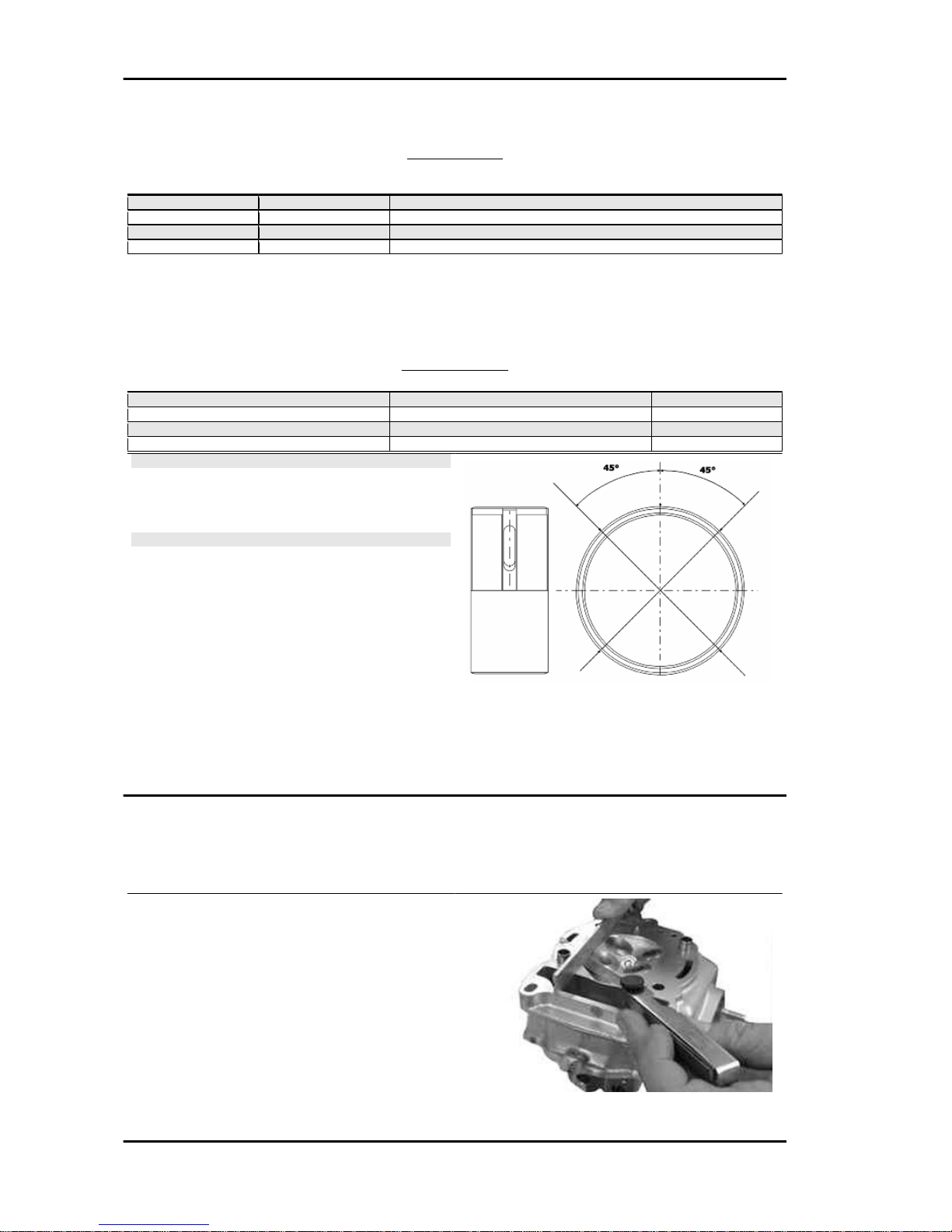
- Carefully clean the sealing ring housings.
- Measure the coupling clearance between the
sealing rings and the grooves using suitable sensors, as shown in the diagram.
- If the clearance is greater than that indicated in
the table, replace the piston.
N.B.
MEASURE THE CLEARANCE BY INSERTING THE BLADE
OF THE FEELER THICKNESS GAUGE FROM THE SECOND
SEAL SIDE.
Fitting clearance
Top piston ring - standard coupling clearance
0.015 - 0.06 mm Top piston ring - maximum clear-
ance allowed after use 0.07 mm Middle piston
ring - standard coupling clearance 0.015 - 0.06 mm
Middle piston ring - maximum clearance allowed after use 0.07 mm oil scraper ring - standard coupling clearance 0.015 - 0.06 mm oil scraper
ring - maximum clearance allowed after use
0.07 mm
MSS Nexus 300 i.e. E3 ( 2008) Characteristics
CHAR - 15
Page 16
- Check that the head coupling surface is not worn
or misshapen.
- Pistons and cylinders are classified according to
diameter. The coupling must be made with those
of the same type (M-M, N-N, O-O, P-P).
Characteristic
Maximum allowable run-out:
0.05 mm
Crankcase - crankshaft - connecting rod
CRANKSHAFT
Titolo Durata/Valore Testo Breve (< 4000 car.) Indirizzo Immagine
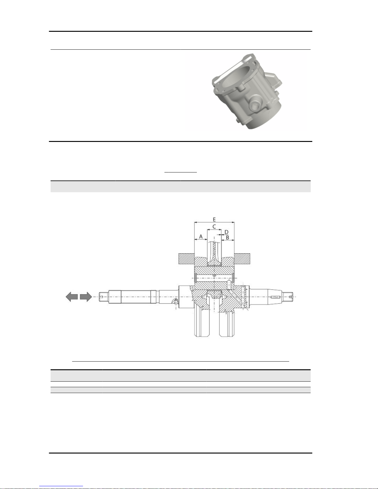
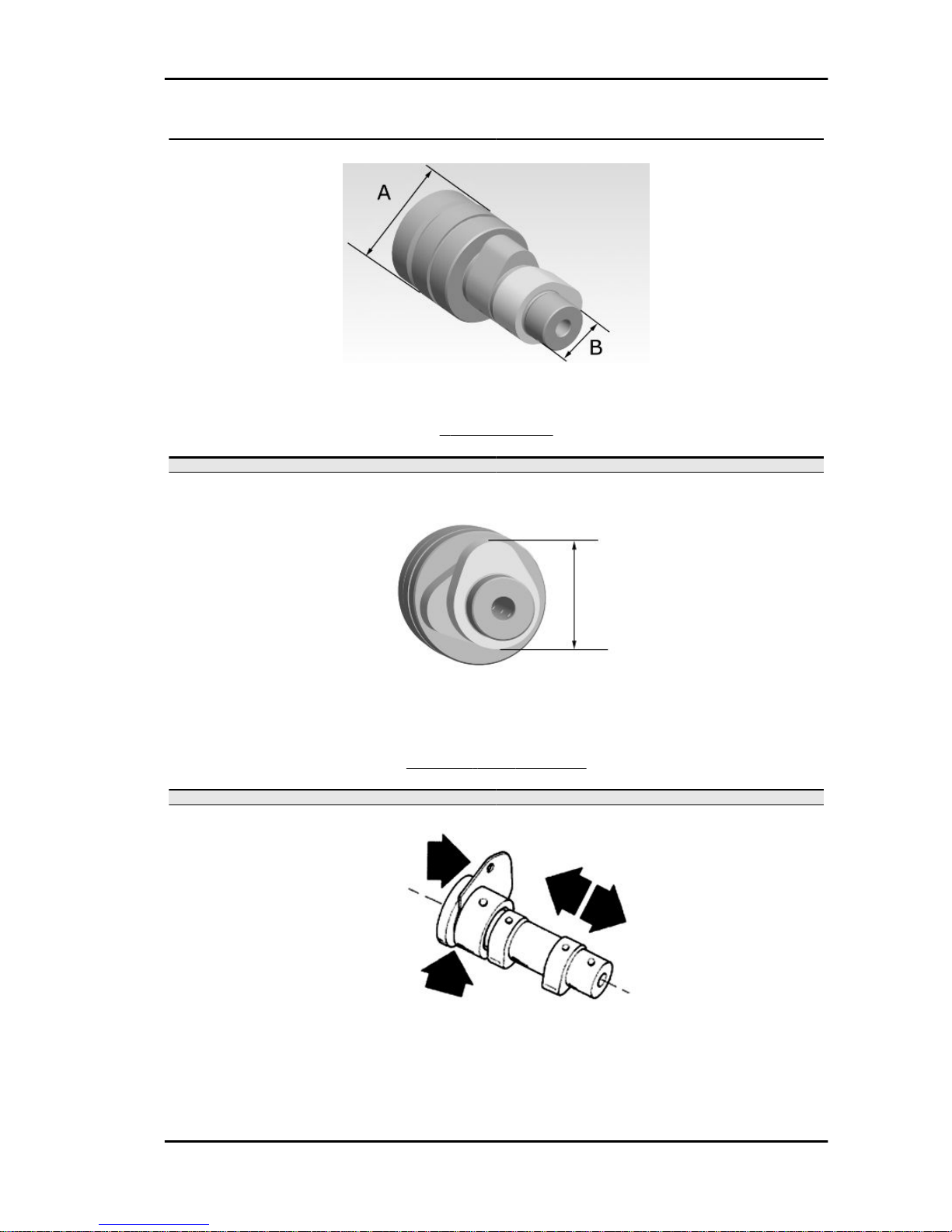
Crankshaft Crankshaft to crankcase axial
clearance
Crankshaft to crankcase axial clearance
AXIAL CLEARANCE BETWEEN CRANKSHAFT AND CONNECTING ROD
Name
Description Dimensions Initials Quantity
Half-shaft, transmission
side
16.6 +0-0.05 A D = 0.20 - 0.50
Flywheel-side half-shaft 16.6 +0-0.05 B D = 0.20 - 0.50
Connecting rod 18 -0.10 -0.15 C D = 0.20 - 0.50
Spacer tool 51.4 +0.05 E D = 0.20 - 0.50
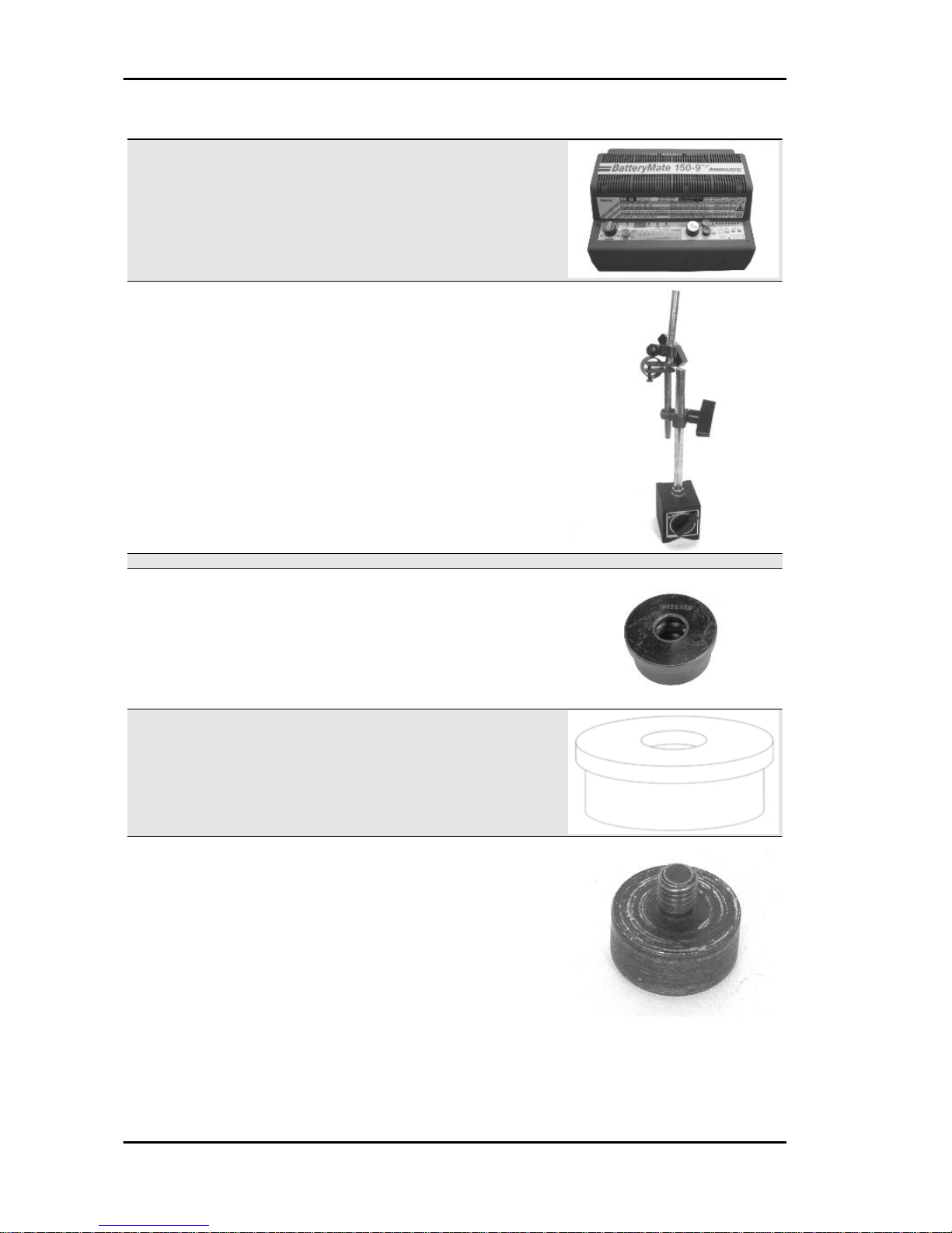
Diameter of crankshaft bearings.
Measure the bearings on both axes x-y.
Characteristics MSS Nexus 300 i.e. E3 ( 2008)
CHAR - 16
Page 17
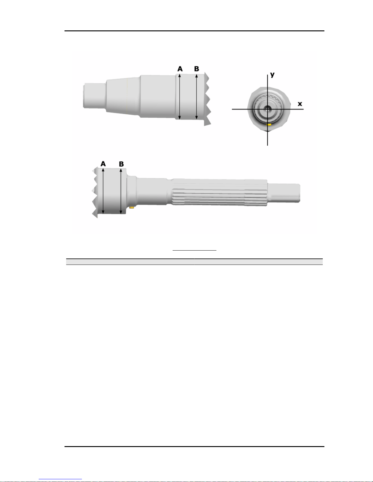
CRANKSHAFT
Specification
Desc./Quantity
Crankshaft bearings: Standard diameter: Cat. 1 28.998 ÷ 29.004 mm
Crankshaft bearings: Standard diameter: Cat. 2 29.004 ÷ 29.010 mm
MSS Nexus 300 i.e. E3 ( 2008) Characteristics
CHAR - 17
Page 18

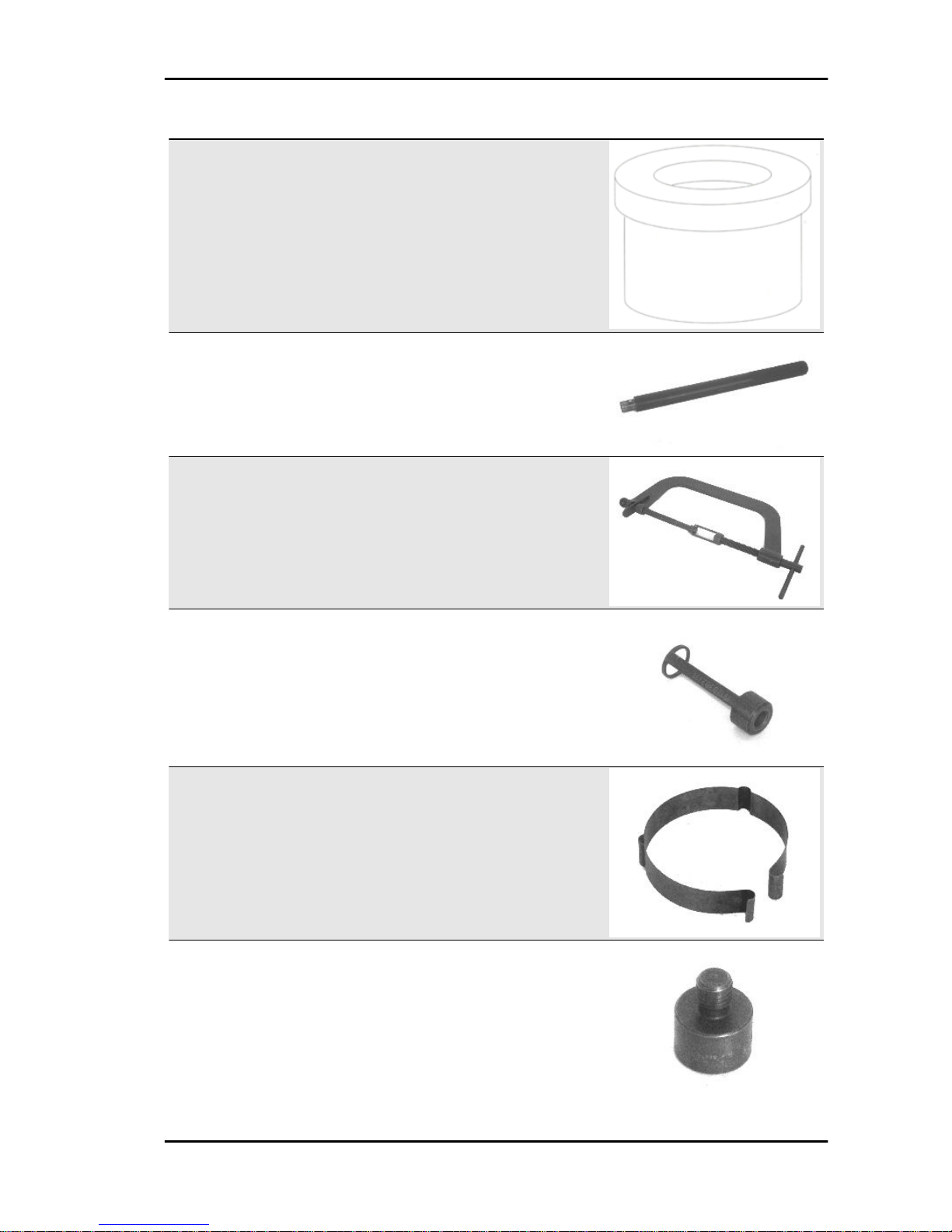
MAX. ADMISSIBLE DISPLACEMENT
Specification
Desc./Quantity
A = 0.15 mm
B = 0.010 mm
C = 0.010 mm
D = 0.10 mm
Characteristics MSS Nexus 300 i.e. E3 ( 2008)
CHAR - 18
Page 19
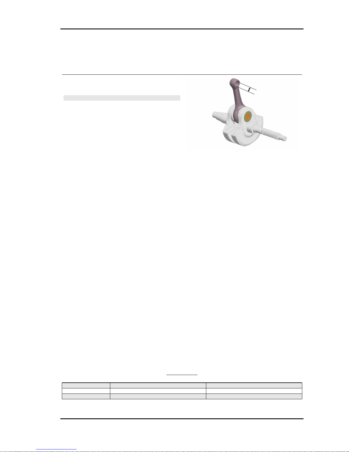
Characteristic
Crankshaft-crankcase axial clearance (H)
0.15 ÷ 0.43 mm
- Using a bore gauge, measure the connecting rod
small end diameter.
N.B.
IF THE CONNECTING ROD SMALL END DIAMETER EX-
CEEDS THE STANDARD DIAMETER, EXHIBITS WEAR OR
OVERHEATING, PROCEED TO REPLACE THE CRANKSHAFT AS DESCRIBED IN THE CRANKCASE AND
CRANKSHAFT CHAPTER.
Characteristic
Standard diameter
16 +0.025 +0.015 mm
- To obtain a good bushing lubrication it is necessary to have both an optimal lubricating pressure and
a good oil flow rate; the bushings must be correctly positioned so as not to obstruct the oil supply
channels.
- The main bushings are comprised of two half-bearings, one with holes and channels for lubrication
whereas the other is solid.
- The solid half-bearing is intended to stand the thrusts caused by combustion, and for this reason it is
arranged opposite the cylinder.
- To prevent obstructions in the oil feeding channels, the matching surface of the two half-bearings must
be perfectly perpendicular to the cylinder axis, as shown in the figure.
- The oil feeding channel section is also affected by the bushings driving depth compared with the
crankshaft axial clearance of the limiting surface.
- Check the inside diameter of the main bushings in the three directions indicated in the diagram.
- Repeat the measurements for the other bushing half. see diagram.
- There are three crankcase versions: with BLUE bushings, with YELLOW bushings and with GREEN
bushings.
- There is only one type of main bushing housing hole in the crankcase. The standard bushing diameter
after driving is variable on the basis of a coupling selection.
- The bushing housings in the crankcase are classified into 2 categories - Cat. 1 and Cat. 2 - just like
those for the crankshaft.
- The main bushings are available in three thickness categories, identified by colour markings, as shown
in the table below.
BUSHINGS
TYPE
IDENTIFICATION CRANKSHAFT HALF-BEARING
B BLUE 1.973 ÷ 1.976
C YELLOW 1.976 ÷ 1.979
E GREEN 1.979 ÷ 1.982
MSS Nexus 300 i.e. E3 ( 2008) Characteristics
CHAR - 19
Page 20
COUPLINGS
BUSHING CATEGORY CRANKCASE
HALVES CATEGORY
BUSHING INSIDE DIAMETER AFTER FITTING
B 2 29.024 ÷ 29.054
C 1 29.024 ÷ 29.054
2 29.018 ÷ 29.048
E 1 29.018 ÷ 29.048
Combine the shaft with two category 1 crankwebs with the category 1 crankcase (or cat. 2 with cat. 2).
Furthermore a spare crankcase cannot be matched with a crankshaft with mixed categories. The spare
crankshaft has half-shafts of the same category.
CATEGORIES
CRANKCASE HALVES ENGINE HALF-SHAFT BUSHING
Cat. 1 Cat. 1 E
Cat. 2 Cat. 2 B
Cat. 1 Cat. 2 C
Cat. 2 Cat. 1 C
N.B.
DO NOT TAKE THE MEASUREMENT ON THE TWO HALF-
SHELL COUPLING SURFACE SINCE THE ENDS ARE RELIEVED TO ALLOW BENDING DURING THE DRIVING
OPERATION.
N.B.
CRANKCASES FOR REPLACEMENTS ARE SELECTED
WITH CRANKCASE HALVES OF THE SAME CATEGORY
AND ARE FITTED WITH CATEGORY C BUSHINGS (YELLOW)
Characteristic
Crankshaft-bushing maximum clearance admitted:
0.08 mm
Diameter of crankcase without bushing
CAT. 1: 32.959 ÷ 32.965 mm
CAT. 2: 32.953 ÷ 32.959 mm
Cylinder Head
Before performing head service operations, thoroughly clean all coupling surfaces. Note the position of
the springs and the valves so as not to change the original position during refitting
- Using a trued bar and a feeler thickness gauge
check that the cylinder head surface is not worn or
distorted.
Characteristic
Maximum allowable run-out:
0.1 mm
- In case of irregularities, replace the head.
Characteristics MSS Nexus 300 i.e. E3 ( 2008)
CHAR - 20
Page 21
- Check the sealing surfaces for the intake and exhaust manifold.
- Check that the bearings of the camshaft and the rocker pins exhibit no wear.
- Check that the head cover surface is not worn.
- Check that the coolant sealing pad exhibits no oxidation.
- Insert the valves into the cylinder head.
- Alternatively check the intake and exhaust
valves.
- The test is carried out by filling the manifold with
petrol and checking that the head does not ooze
through the valves when these are just pressed
with the fingers.
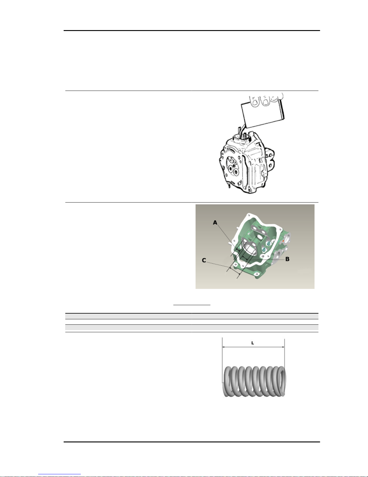
Measure the camshaft bearing seats and rocking
lever support pins with a bore meter
HEAD BEARINGS
Specification
Desc./Quantity
bearing «A» Ø 12.000 - 12.018 mm
bearing «B» Ø 20.000 ÷ 20.021 mm
bearing «C» Ø 37.000 - 37.025 mm
Measure the unloaded spring length
Characteristic
Standard length
40.2 mm
Allowable limit after use:
38.2 mm
MSS Nexus 300 i.e. E3 ( 2008) Characteristics
CHAR - 21
Page 22
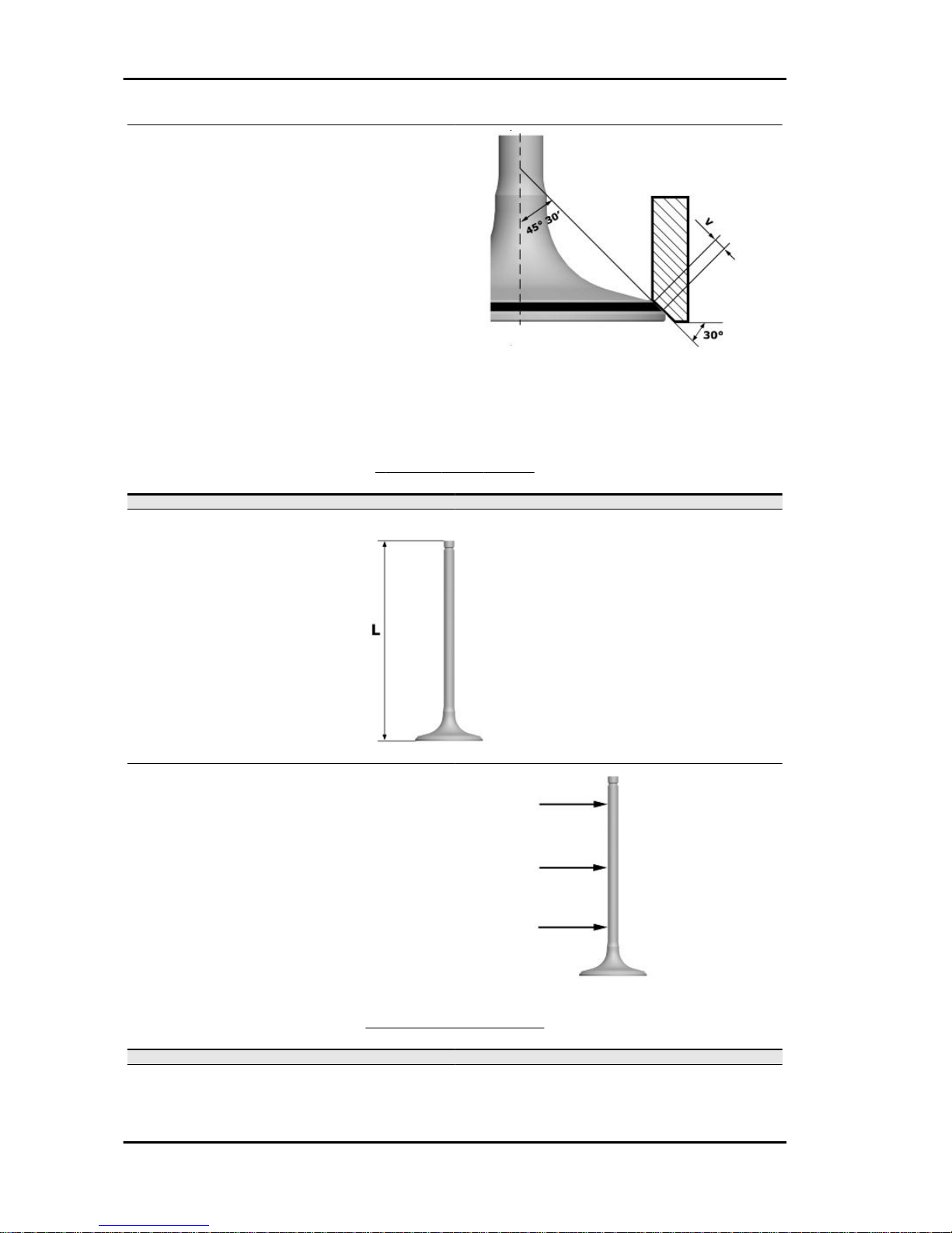
- Clean the valve seats of any carbon residues.
- Using the Prussian blue, check the width of the
impression on the valve seat "V".
Characteristic
Standard value:
1 - 1.3 mm
Admissible limit:
1.6 mm
- If the impression width on the valve seat is larger than the prescribed limits, true the seats with a 45°
mill and then grind.
- In case of excessive wear or damages, replace the head.
STANDARD VALVE LENGTH
Specification Desc./Quantity
Valve check standard length Inlet: 94.6 mm
Valve check standard length Outlet: 94.4 mm
- Measure the diameter of the valve stems in the
three positions indicated in the diagram.
STANDARD DIAMETER
Specification
Desc./Quantity
Inlet: 4.987 - 4.972 mm
Outlet: 4.975 - 4.960 mm
Characteristics MSS Nexus 300 i.e. E3 ( 2008)
CHAR - 22
Page 23
MINIMUM ADMISSIBLE DIAMETER
Specification Desc./Quantity
Inlet: 4.96 mm
Outlet: 4.945 mm
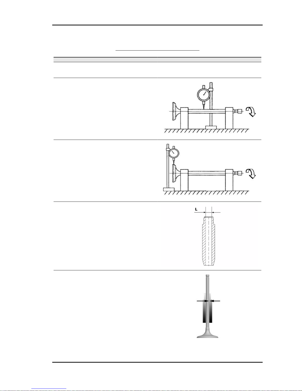
- Calculate the clearance between valve and valve guide.
- Check the deviation of the valve stem by resting
it on a "V" shaped abutment and measuring the
extent of the deformation with a comparator.
Characteristic
Limit values admitted:
0.1 mm
- Check the concentricity of the valve head by arranging a comparator at right angle relative to the
valve head and rotate it on a "V" shaped abutment.
Characteristic
Admissible limit:
0.03 mm
Measure the valve guide.
Characteristic
Valve guide:
5 +0.012 mm
- After measuring the valve guide diameter and the
valve stem diameter, check the clearance between guide and stem.
MSS Nexus 300 i.e. E3 ( 2008) Characteristics
CHAR - 23
Page 24
INLET
Specification Desc./Quantity
Standard clearance: 0.013 - 0.04 mm
Admissible limit: 0.08 mm
OUTLET
Specification Desc./Quantity
Standard clearance: 0.025 ÷ 0.052 mm
Admissible limit: 0.09 mm
- Check that there are no signs of wear on the surface of contact with the articulated register terminal.
- If the checks above give no failures, you can use
the same valves. To obtain better sealing performance, grind the valve seats. Grind the valves gently
with a fine-grained lapping compound. During the
grinding, keep the cylinder head with the valve axes in a horizontal position. This will prevent the
lapping compound residues from penetrating between the valve stem and the guide (see figure).
CAUTION
TO AVOID SCORING THE FAYING SURFACE, DO NOT KEEP ROTATING THE VALVE WHEN NO
LAPPING COMPOUND IS LEFT. CAREFULLY WASH THE CYLINDER HEAD AND THE VALVES
WITH A SUITABLE PRODUCT FOR THE TYPE OF LAPPING COMPOUND BEING USED.
CAUTION
DO NOT REVERSE THE FITTING POSITIONS OF THE VALVES (RIGHT - LEFT).
- Check that the camshaft bearings exhibit no scores or abnormal wear.
- Using a micrometer, measure the camshaft bearings.
STANDARD DIAMETER
Specification
Desc./Quantity
Cam shaft check: Standard diameter Bearing A Ø: 36.95 ÷ 36.975 mm
Cam shaft check: Standard diameter Bearing B diameter: 19.959 ÷ 19.98 mm
MINIMUM DIAMETER PERMITTED
Specification
Desc./Quantity
Cam shaft check: Minimum admissible diameter Bearing A Ø: 36.94 mm
Characteristics MSS Nexus 300 i.e. E3 ( 2008)
CHAR - 24
Page 25
Specification Desc./Quantity
Cam shaft check: Minimum admissible diameter Bearing B diameter: 19.950 mm
-Using a gauge, measure the cam height.
STANDARD HEIGHT
Specification Desc./Quantity
Cam shaft check: Standard height Inlet: 30.285 mm
Cam shaft check: Standard height Outlet: 29.209 mm
Check the axial clearance of the camshaft
CAMSHAFT AXIAL CLEARANCE
Specification
Desc./Quantity
Cam shaft check: Standard axial clearance: 0.11 - 0.41 mm
Cam shaft check: Maximum admissible axial clearance 0.42 mm
- Measure the outside diameter of the rocking lever pins
- Check the rocking lever pins do not show signs of wear or scoring.
- Measure the inside diameter of each rocking lever.
MSS Nexus 300 i.e. E3 ( 2008) Characteristics
CHAR - 25
Page 26

Check there are no signs of wear on the pad from contact with the cam and on the jointed adjustment
plate.
ROCKING LEVERS AND PIN DIAMETER:
Specification Desc./Quantity
Internal rocker arm diameter: Standard diameter Diameter 12.000 - 12.011 mm
Rocking lever pin diameter: Standard diameter Diameter 11.977 - 11.985 mm
Slot packing system
Characteristic
Compression ratio
10.5 ÷ 11.5 : 1
Measurement "A" to be taken is a value of piston re-entry, it indicates by how much the plane formed
by the piston crown falls below the plane formed by the top of the cylinder. The further the piston falls
Characteristics MSS Nexus 300 i.e. E3 ( 2008)
CHAR - 26
Page 27

inside the cylinder, the less the base gasket to be applied (to recover the compression ratio) and vice
versa.
N.B.
MEASUREMENT "A" MUST BE TAKEN WITHOUT ANY GASKET FITTED BETWEEN THE CRANKCASE AND CYLINDER AND AFTER RESETTING THE GAUGE, EQUIPPED WITH A SUPPORT, ON
A GROUND PLANE
ENGINE 300 SHIMMING
Name Measure A Thickness
shimming 3.70 - 3.60 0.4 ± 0.05
shimming 3.60 - 3.40 0.6 ± 0.05
shimming 3.40 - 3.30 0.8 ± 0.05
Products
RECOMMENDED PRODUCTS TABLE
Product Description Specifications
AGIP GEAR 80W-90 Oil for speed gearbox SAE 80W-90, API GL-4 mineral multi-
grade oil
AGIP CITY HI TEC 4T Oil to lubricate flexible transmissions
(throttle control)
Oil for 4-stroke engines
AGIP GP 330 Grease for brake levers, throttle White calcium complex soap-based
spray grease with NLGI 2; ISO-L-XBCIB2
AGIP CITY HI TEC 4T Engine oil SAE 5W-40, API SL, ACEA A3, JASO MA
Synthetic oil
AGIP BRAKE 4 Brake fluid FMVSS DOT 4 Synthetic fluid
AGIP PERMANENT SPEZIAL coolant Monoethylene glycol-based antifreeze
fluid, CUNA NC 956-16
AUTOSOL METAL POLISH Muffler cleaning paste special product for cleaning and polishing
stainless steel muffler
AGIP GREASE PV2 Grease for the steering bearings, pin
seats and swinging arm
Soap-based lithium and zinc oxide
grease containing NLGI 2; ISO-L-
XBCIB2 of the swinging arm
AGIP GREASE SM 2 Grease for the tone wheel revolving ring Soap-based lithium grease containing
NLGI 2 Molybdenum disulphide; ISO-L-
XBCHB2, DIN KF2K-20
MSS Nexus 300 i.e. E3 ( 2008) Characteristics
CHAR - 27
Page 28

INDEX OF TOPICS
TOOLING TOOL
Page 29

SPECIFIC TOOLS
Stores code Description
001330Y Tool for fitting steering seats
001467Y014 Pliers to extract ø 15-mm bearings
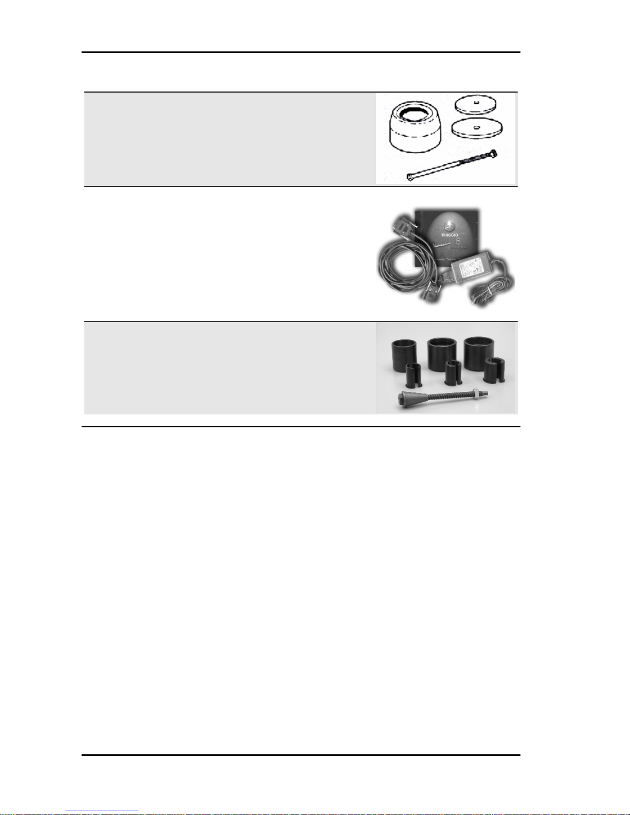
005095Y Engine support
002465Y Pliers for circlips
020459Y Punch for fitting bearing on steering tube
020004Y Punch for removing fifth wheels from
headstock
020055Y Wrench for steering tube ring nut
MSS Nexus 300 i.e. E3 ( 2008) Tooling
TOOL - 29
Page 30

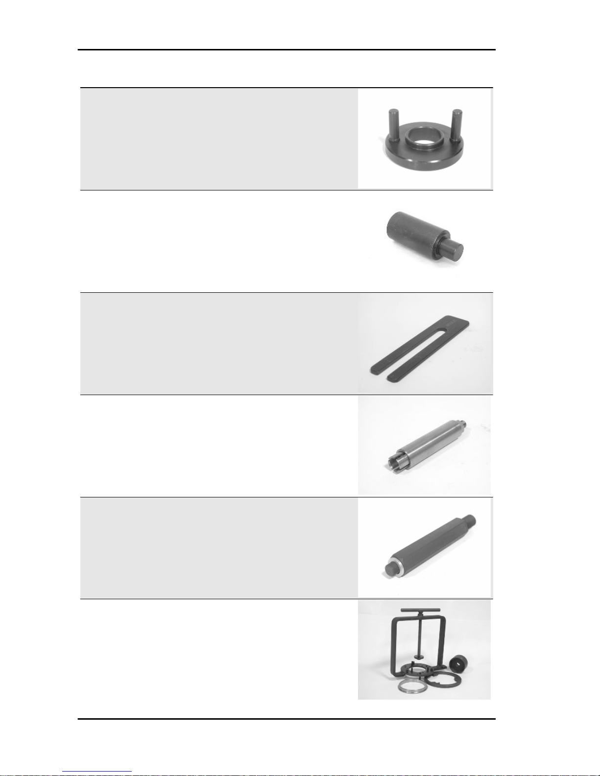
Stores code Description
020074Y Support base for checking crankshaft
alignment
020150Y Air heater support
020151Y Air heater
020193Y Oil pressure gauge
020262Y Crankcase splitting strip
020263Y Sheath for driven pulley fitting
Tooling MSS Nexus 300 i.e. E3 ( 2008)
TOOL - 30
Page 31

Stores code Description
020306Y Punch for assembling valve seal rings
020329Y MityVac vacuum-operated pump
020330Y Stroboscopic light to check timing
020331Y Digital multimeter
020332Y Digital rev counter
MSS Nexus 300 i.e. E3 ( 2008) Tooling
TOOL - 31
Page 32
Stores code Description
020648Y Single battery charger
020335Y Magnetic support for dial gauge
020357Y 32 x 35 mm adaptor
020359Y 42x47-mm adaptor
020360Y Adaptor 52 x 55 mm
020363Y 20 mm guide
Tooling MSS Nexus 300 i.e. E3 ( 2008)
TOOL - 32
Page 33
Stores code Description
020375Y Adaptor 28 x 30 mm
020376Y Adaptor handle
020382Y Valve cotters equipped with part 012 re-
moval tool
020382Y011 adapter for valve removal tool
020393Y Piston fitting band
020412Y 15 mm guide
MSS Nexus 300 i.e. E3 ( 2008) Tooling
TOOL - 33
Page 34
Stores code Description
020423Y driven pulley lock wrench
020424Y Driven pulley roller casing fitting punch
020426Y Piston fitting fork
020431Y Valve oil seal extractor
020434Y Oil pressure control fitting
020444Y Tool for fitting/ removing the driven pulley
clutch
Tooling MSS Nexus 300 i.e. E3 ( 2008)
TOOL - 34
Page 35
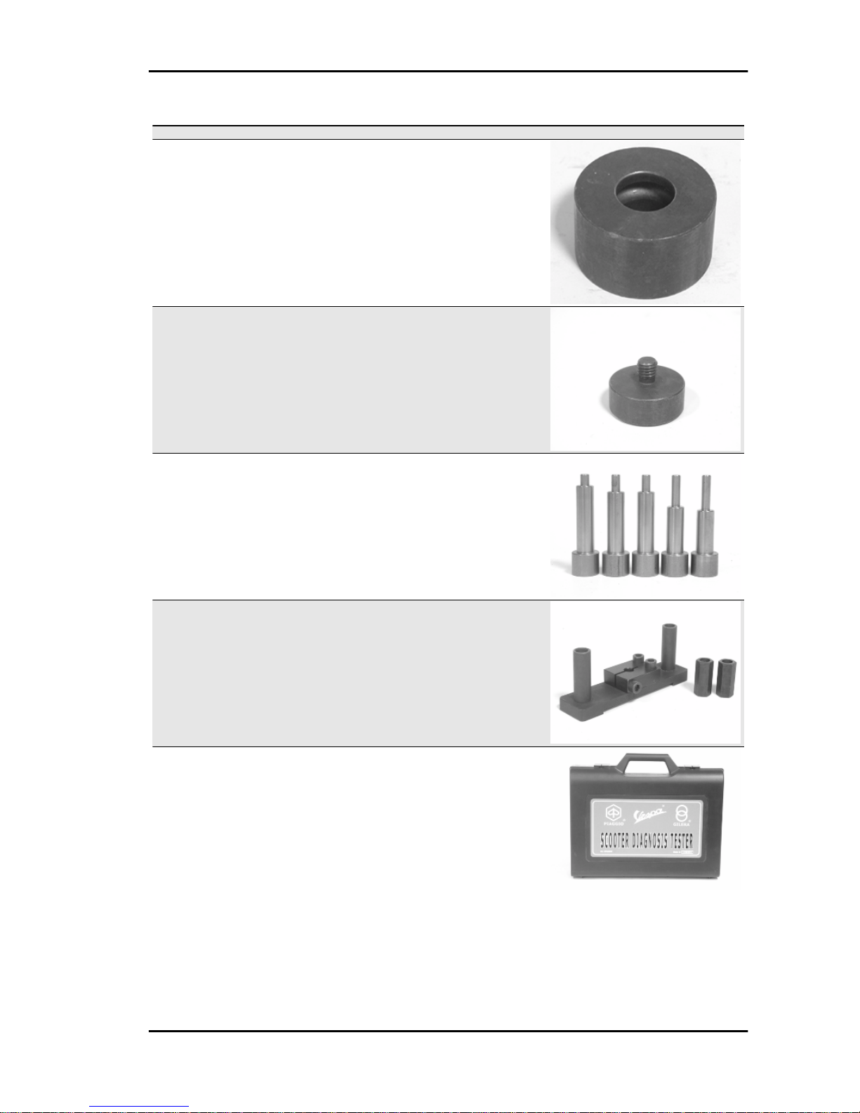
Stores code Description
020456Y Ø 24 mm adaptor
020477Y Adaptor 37 mm
020483Y 30 mm guide
020489Y Hub cover support stud bolt set
020428Y Piston position check support
020460Y Scooter diagnosis and tester
MSS Nexus 300 i.e. E3 ( 2008) Tooling
TOOL - 35
Page 36
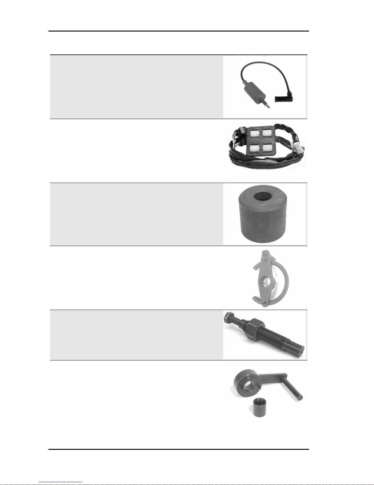
Stores code Description
020621Y HV cable extraction adaptor
020481Y Control unit interface wiring
001467Y035 Belle for OD 47-mm bearings
020626Y Driving pulley lock wrench
001467Y013 Pliers to extract ø 15-mm bearings
020627Y Flywheel lock wrench
Tooling MSS Nexus 300 i.e. E3 ( 2008)
TOOL - 36
Page 37
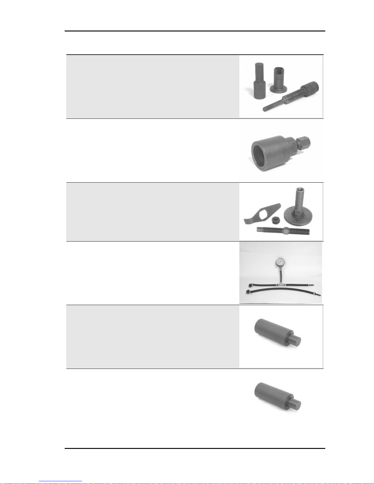
Stores code Description
020454Y Pin lock fitting tool
020467Y Flywheel extractor
020622Y Transmission-side oil guard punch
020480Y Petrol pressure check set
020244Y 15 mm diameter punch
020115Y Ø 18 punch
MSS Nexus 300 i.e. E3 ( 2008) Tooling
TOOL - 37
Page 38
Stores code Description
020271Y Tool for removing-fitting silent bloc
020469Y Reprogramming kit for scooter diagnosis
tester
020487Y Fork oil seal extractor
Tooling MSS Nexus 300 i.e. E3 ( 2008)
TOOL - 38
Page 39

INDEX OF TOPICS
MAINTENANCE MAIN
Page 40

Maintenance chart
SCHEDULED MAINTENANCE TABLE
I: CHECK AND CLEAN, ADJUST, LUBRICATE OR REPLACE IF NECESSARY.
C: CLEAN, R: REPLACE, A: ADJUST, L: LUBRICATE
Clean the SAS air filter every 2 years
* Replace every 2 years
km x 1,000 1 5 10 15 20 25 30 35 40 45 50 55 60
Safety locks I I I I I
Spark plug R R R R R R
Driving belt R R R R
Throttle control A A A A A A A
Air filter C C C C C C
Belt compartment air filter I I I I I I
Oil filter R R R R R R R
Oil filter (mesh) C
Valve clearance A A A
Electrical system and battery I I I I I I I
Brake fluid * I I I I I I I
Coolant * I I I I I I I
Engine oil R I R I R I R I R I R I R
Hub oil R I R I R I R
Brake pads I I I I I I I I I I I I I
Sliding blocks / variable speed rollers R R R R R R
Tyre pressure and wear I I I I I I I
Vehicle road test I I I I I I I
Suspensions I I I I I I
Steering A A A A A A A
Centre stand L L
Checking the spark advance
The ignition advance is determined electronically
on the basis of parameters known by the control
unit. For this reason it is not possible to declare the
reference values based on the engine rpm. The
ignition timing value is detectable any time using
the diagnostic tester. It is possible to check whether the ignition advance determined by the system
does in fact correspond with the value actually activated on the engine, by means of the stroboscopic light.
Proceed as follows:
- Remove the spark plug.
- Remove the transmission crankcase.
- Rotate the driving pulley fan until the reference
marks between the flywheel and flywheel cover
coincide as shown in the photograph.
Maintenance MSS Nexus 300 i.e. E3 ( 2008)
MAIN - 40
Page 41

- Bring the reference mark onto the transmission
side between the fan and the transmission cover
as shown in the photograph.
- Refit the spark plug.
- Refit the plastic cap on the flywheel cover.
- Adjust the spark gap to the contact position (no
reference mark visible) and install it on engine between the spark plug and spark plug cap
- Connect the induction calliper on the spark gap
cable respecting the proper polarity (the arrow on
the calliper must be pointing at the spark plug).
- Connect the diagnostic tester.
- Start the engine.
- Select the «parameter» function in this menu.
- Select the stroboscopic light command in the traditional four-stroke engine position (1 spark 2
revs).
- Check that the real values of rpm and ignition
advance match those measured using the diagnostic tester.
If the values do not correspond, check:
- distribution timing
- revolution-timing sensor
- Injection control unit
Specific tooling
020460Y Scooter diagnosis and tester
020330Y Stroboscopic light to check timing
020621Y HV cable extraction adaptor
MSS Nexus 300 i.e. E3 ( 2008) Maintenance
MAIN - 41
Page 42

Spark plug
Proceed as follows:
1. Remove the right side cover unscrewing the 3
«A» screws;
2. Disconnect the spark plug HV wire hood «B» ;
3. Unscrew the spark plug using the wrench supplied. ;
4. When refitting, place the spark plug in the hole
at the due inclination and tighten it by hand until it
is finger tight;
5. Only use the wrench to lock it in place;
6. Push hood «B» fully over the spark plug.
WARNING
THE USE OF SPARK PLUGS OTHER THAN THOSE REC-
OMMENDED OR A SHIELDLESS SPARK PLUG CAP
COULD CAUSE DISTURBANCES TO THE SYSTEM.
WARNING
THE SPARK PLUG MUST BE REMOVED WHEN THE ENGINE IS COLD. REPLACE THE SPARK PLUG AS INDICATED IN THE SCHEDULED MAINTENANCE TABLE. THE
USE OF ELECTRONIC CENTRAL UNITS AND OF NONCOMPLIANT ELECTRONIC IGNITIONS OR SPARK PLUGS
OTHER THAN THOSE PRESCRIBED MAY SERIOUSLY
DAMAGE THE ENGINE.
Characteristic
Spark plug
NGK CR8EKB
Electric characteristic
Electrode gap
0.7 ÷ 0.8 mm
Locking torques (N*m)
Spark plug 12 ÷ 14
Hub oil
Maintenance MSS Nexus 300 i.e. E3 ( 2008)
MAIN - 42
Page 43

Check
-Park the vehicle on its centre stand on flat ground;
- Remove the oil dipstick «A», dry it with a clean
cloth and put it back into its hole tightening it
completely;
Remove the dipstick and check that the oil level is
slightly over the second notch starting from the
lower end; if the level is under the MAX. mark, it
needs to be filled with the right amount of hub oil.
-Screw up the oil dipstick again and make sure it
is locked properly into place.
Replacement
-Remove the oil filler cap «A».
- Unscrew the oil drainage cap "B" and drain out
all the oil.
- Screw in the drainage cap again and fill the hub
with the prescribed oil.
Recommended products
AGIP ROTRA 80W-90 Rear hub oil
SAE 80W/90 Oil that exceeds the requirements of
API GL3 specifications
Characteristic
Rear hub oil
Capacity approximately 250 cc
Locking torques (N*m)
Hub oil drainage screw 15 ÷ 17 Nm
MSS Nexus 300 i.e. E3 ( 2008) Maintenance
MAIN - 43
Page 44

Air filter
Proceed as follows:
1. Unscrew the 9 fixing screws «A»;
2. Remove the air filter«B»
CAUTION
IF THE VEHICLE IS USED ON DUSTY ROADS, IT IS NECESSARY TO SERVICE THE AIR FILTER MORE OFTEN TO
AVOID DAMAGING THE ENGINE.
1. Wash the sponge with water and neutral soap.
2. Dry it with a clean cloth and small blasts of compressed air.
3. Impregnate the sponge with a mixture of 50% petrol and 50% specified oil.
4. Gently squeeze the filter element, let it drip and then refit it.
CAUTION
IF THE VEHICLE IS USED ON DUSTY ROADS, IT IS NECESSARY TO SERVICE THE AIR FILTER
MORE OFTEN TO AVOID DAMAGING THE ENGINE.
Recommended products
AGIP FILTER OIL Oil for air filter sponge
Mineral oil with specific additives for increased adhesiveness
Engine oil
In 4T engines, the engine oil is used to lubricate the distribution elements, the bench bearings and the
thermal group. An insufficient quantity of oil can cause serious damage to the engine.
In all 4T engines, the deterioration of the oil characteristics, or a certain consumption should be considered normal, especially if during the run-in period. Consumption levels in particular can be influenced
by the conditions of use (e.g.: oil consumption increases when driving at "full throttle".
Maintenance MSS Nexus 300 i.e. E3 ( 2008)
MAIN - 44
Page 45

Replacement
Change oil and replace filter as indicated in the
scheduled maintenance table. Empty the engine
by draining the oil through drainage plug «B».
To facilitate oil drainage, loosen the cap/dipstick
«A».
Once all the oil has drained through the drainage
hole, unscrew and remove the oil cartridge filter
«C ».
Make sure the pre-filter and drainage plug O-rings
are in good conditions.
Lubricate them and refit the mesh filter and oil
drainage plug, screwing them up to the specified
torque.
Refit the new cartridge filter being careful to lubricate the O-ring before fitting it.
Change the engine oil.
Since a certain quantity of oil still remains in the
circuit, engine oil must be added through plug
«A». Then start the scooter, leave it running for a
MSS Nexus 300 i.e. E3 ( 2008) Maintenance
MAIN - 45
Page 46

few minutes and switch it off: after five minutes
check the level and if necessary top up without
exceeding the MAX level. The cartridge filter must
be replaced every time the oil is changed. Use new
oil of the recommended type for topping up and
changing purposes.
N.B.
THE ENGINE MUST BE HOT WHEN THE OIL IS CHANGED.
Recommended products
AGIP CITY HI TEC 4T Engine oil
SAE 5W-40 Synthetic oil that exceed the requirements of API SL, ACEA A3, JASO MA specifications
Locking torques (N*m)
Oil filter 4 ÷ 6 Engine oil drainage plug 24 ÷ 30
Check
This operation must be carried out with the engine
cold and following the procedure below:
- Place the vehicle on its centre stand and on flat
ground.
- Unscrew the cap/dipstick "A", dry it with a clean
cloth and reinsert it, screwing it all the way
down.
- Remove the cap/dipstick again and check that
the level is between the min and max reference
marks; top-up, if required.
If the check is carried out after the vehicle has
been used, and therefore with a hot engine, the
level line will be lower; in order to carry out a correct check, wait at least 10 minutes after the engine has been stopped so as to get the correct
level.
Maintenance MSS Nexus 300 i.e. E3 ( 2008)
MAIN - 46
Page 47

Oil top up
The oil should be topped up after having checked
the level and in any case by adding oil without
ever exceeding the MAX. level.
Restoring the level from the MIN to the MAX marks
requires approx. 400 m³ of oil.
Engine oil filter
The cartridge filter must be replaced every time the oil is changed. Use new oil of the recommended
type for topping up and changing purposes.
Make sure the pre-filter and drainage plug O-rings are in good conditions. Lubricate them and refit the
mesh filter and oil drainage plug, screwing them up to the specified torque. Refit the new cartridge filter
being careful to lubricate the O-ring before fitting it. Change the engine oil.
Recommended products
AGIP CITY HI TEC 4T Engine oil
SAE 5W-40 Synthetic oil that exceed the requirements of API SL, ACEA A3, JASO MA specifications
Oil pressure warning light
Warning light (low oil pressure)
The vehicle is equipped with a warning light on the
instrument panel that lights up when the key is
turned to the «ON» position. However, this light
should switch off once the engine has been started.
If the light comes on during braking, at idling
speed or while turning, it is necessary to first
switch off the engine and then to check the oil
level and the lubrication system
MSS Nexus 300 i.e. E3 ( 2008) Maintenance
MAIN - 47
Page 48
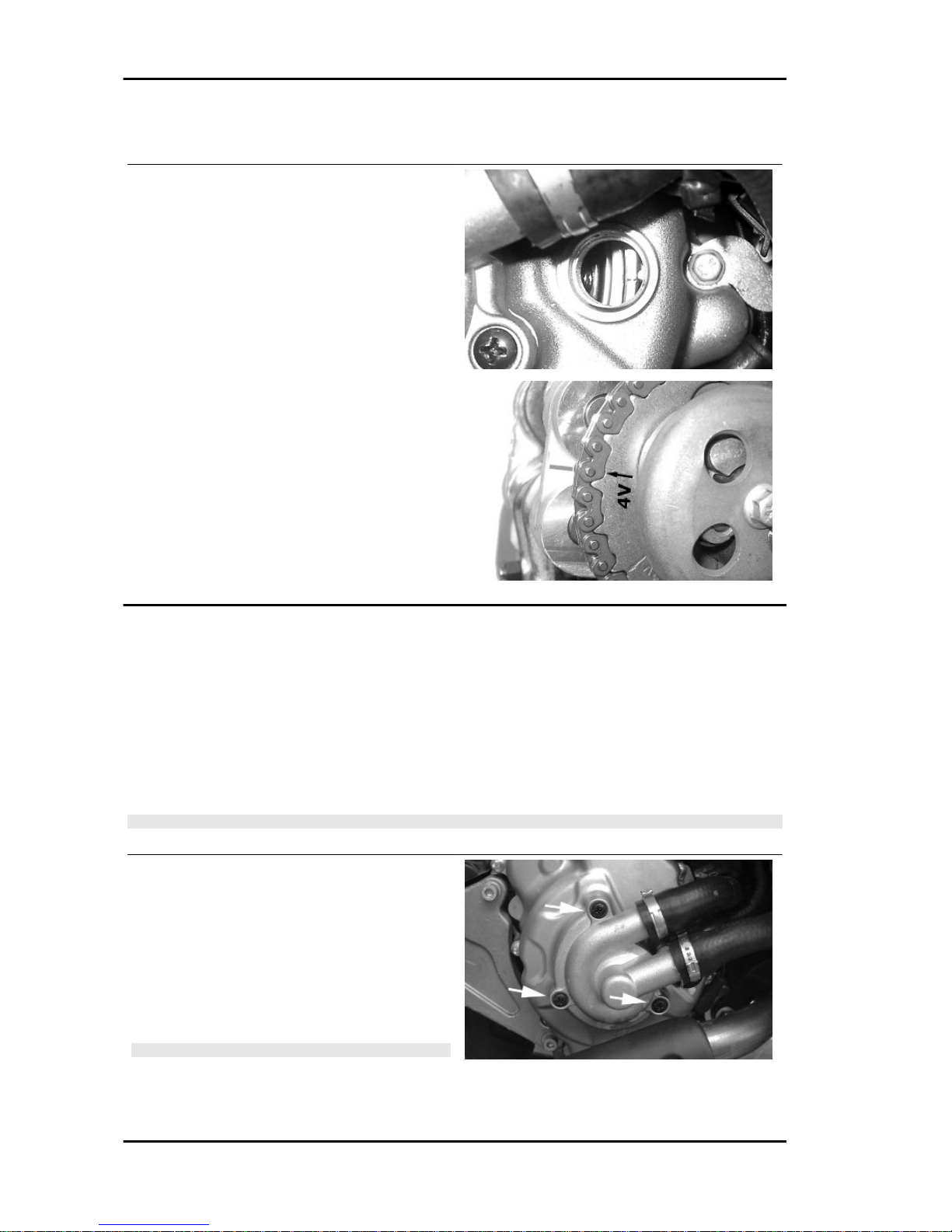
Checking the ignition timing
- Remove the plastic cap on the flywheel cover
-Turn the flywheel until the reference mark «T» on
the rotor matches the reference mark on the flywheel cover as shown in the figure (TDC). Make
sure that the 4V reference point on the camshaft
control pulley is aligned with the reference point on
the head as shown in the second figure. If the reference is opposite the indicator on the head, turn
the crankshaft once more.
For the use of this reference mark, remove the
spark plug and turn the engine in the direction that
is the reverse of the normal direction using a calliper spanner applied to the camshaft command
pulley casing.
Cooling system
If noise or liquid leaks through the drain bore of the water pump is detected, it will be necessary to
replace the pump as described in the «Flywheel cover» Chapter.
Proceed to carry out a few preliminary operations as described below:
- Place the vehicle on its centre stand and on flat ground.
- Empty the cooling system by removing the couplings on the pump cover and the filler plug on the
expansion tank.
CAUTION
THIS OPERATION MUST BE CARRIED OUT WHEN THE ENGINE IS COLD.
- Remove the water pump cover as indicated in the
figure by loosening the 3 fixing screws.
- Proceeding as described in chapter «Engine»,
partially drain the system and overhaul the pump.
- Refill and drain the system again once after having repaired the damaged and reinstalled all the
components.
N.B.
FOR CHANGING THE COOLANT AND BLEEDING THE
SYSTEM, SEE CHAPTER "COOLING SYSTEM".
Characteristic
Maintenance MSS Nexus 300 i.e. E3 ( 2008)
MAIN - 48
Page 49
Cooling system
approx. 1.8 litres
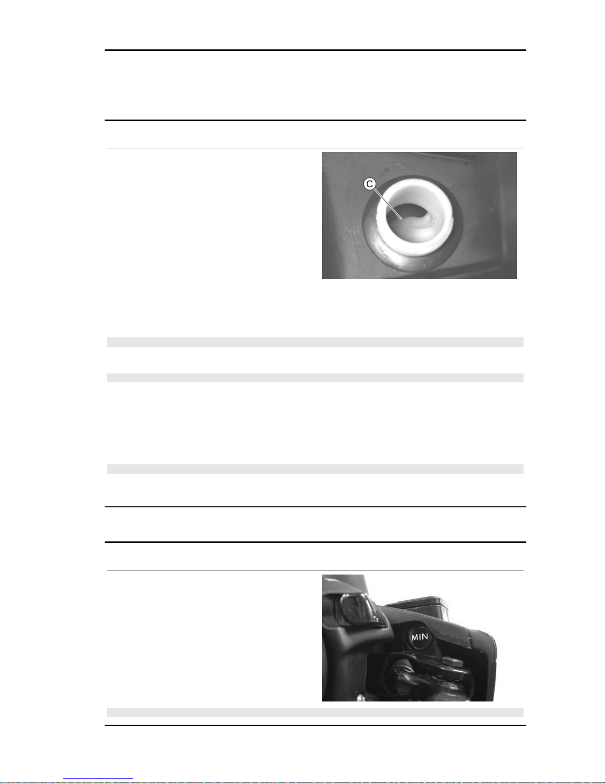
Level check
Check coolant level when the engine is cold and
as indicated in the scheduled maintenance table,
following the steps below:
- Place the vehicle on its centre stand and on flat
ground.
- Remove the expansion tank cap.
- To check the level, it is necessary to look inside
the expansion tank:
Reference «C» shows the adequate coolant level.
-The coolant consists of an ethylene glycol and corrosion inhibitor based 50% de-ionised water- antifreeze solution mix.
CAUTION
DO NOT EXCEED THE MAX. LEVEL WHEN FILLING SO AS TO AVOID THE COOLANT ESCAPING
FROM THE EXPANSION TANK WHEN THE vehicle IS IN USE.
N.B.
THE COOLANT CONSISTS OF A MIXTURE OF DE-IONISED WATER AND FLUID FOR SEALED
CIRCUITS. THE MIXTURE THUS OBTAINED LOWERS THE FREEZING POINT OF THE COOLANT
TO - 40°C. THE MIXTURE IN COMBINATION WITH THE PRESSURE OF 0.9 BAR RAISES THE
BOILING POINT TO APPROX. 125°C. THE RECOMMENDED LIQUID ALSO PROVIDES PROTECTIVE FUNCTIONS FOR THE ALUMINIUM ALLOYS. THIS CHARACTERISTIC MAY DECREASE
OVER THE COURSE OF TIME; THIS IS WHY A PERIODIC REPLACEMENT OF THE COOLANT IS
INDISPENSABLE.
N.B.
FOR THE REPLACEMENT OF THE COOLANT AND THE FLUSHING OF THE SYSTEM, SEE
CHAPTER COOLING SYSTEM.
Braking system
Level check
- Position the vehicle on a flat surface and on the
centre stand.
- Check the brake fluid level via the special indicator located on the pump.
N.B.
MSS Nexus 300 i.e. E3 ( 2008) Maintenance
MAIN - 49
Page 50
THE LEVEL TENDS TO DROP AS THE BRAKE PADS GET WORN, A MINIMUM LEVEL SHOULD
NOT BE REACHED. IF THE LEVEL IS TOO LOW, CHECK AND FIX THE SYSTEM SEALS, IF REQUIRED. TOP UP THE PUMP TANK, IF REQUIRED, CONSIDERING THAT THE "MAX." LEVEL
MUST ONLY BE OBTAINED WITH NEW PADS.
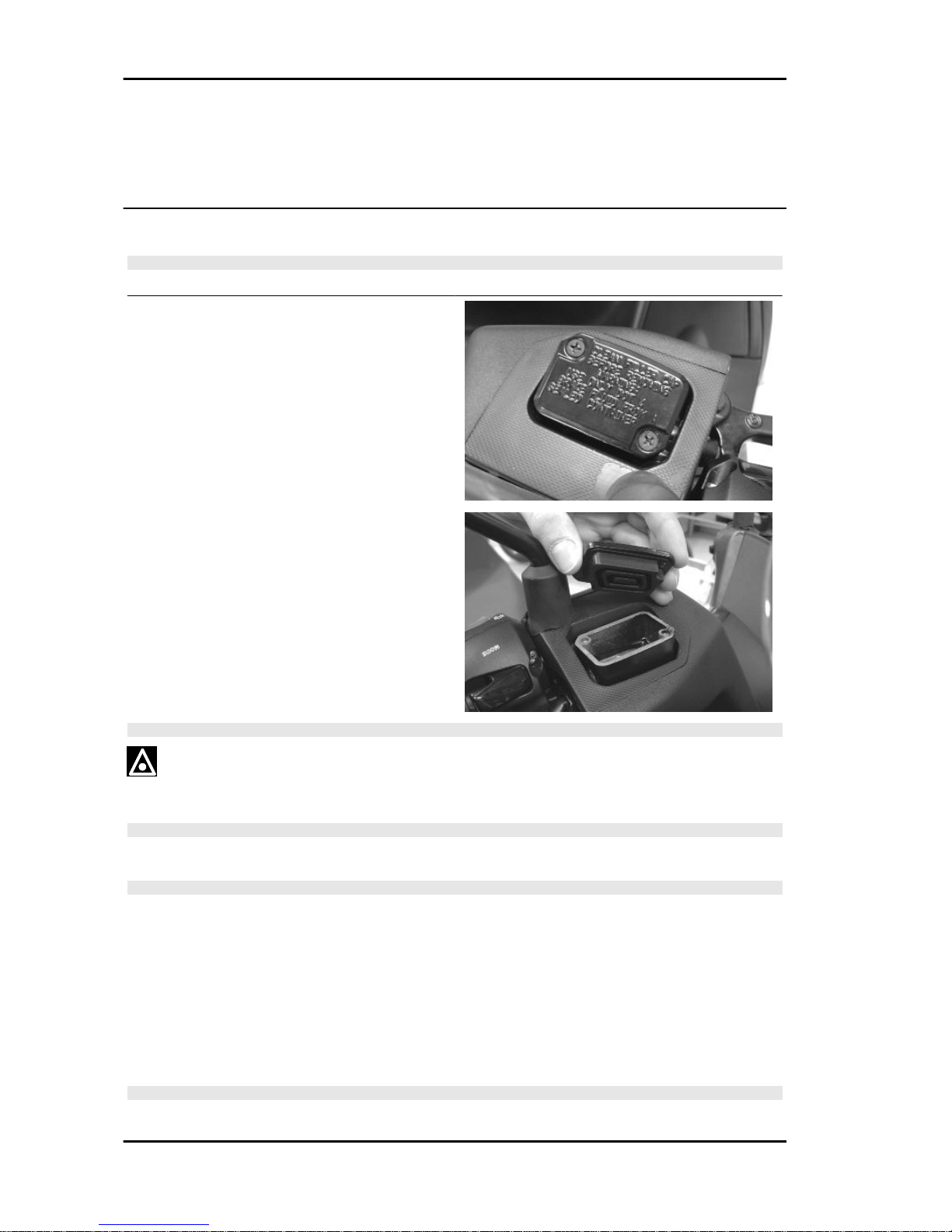
Top-up
CAUTION
ONLY USE DOT 4-CLASSIFIED BRAKE FLUID.
Proceed as follows:
- Position the vehicle on a flat surface and on the
centre stand.
- Remove the tank cap by removing the two
screws, remove the gasket and top up using only
the liquid specified without exceeding the maximum level.
CAUTION
AVOID CONTACT OF THE BRAKE FLUID WITH YOUR EYES, SKIN, AND CLOTHING. IN CASE
OF ACCIDENTAL CONTACT, WASH WITH WATER.
WARNING
BRAKE CIRCUIT FLUID IS VERY CORROSIVE; DO NOT LET IT COME INTO CONTACT WITH
PAINTED PARTS.
WARNING
THE BRAKE FLUID IS HYGROSCOPIC, THAT IS, IT ABSORBS MOISTURE FROM THE SURROUNDING AIR. IF THE HUMIDITY IN THE BRAKING FLUID EXCEEDS A CERTAIN VALUE, IT
WILL LEAD TO INEFFICIENT BRAKING; FOR THIS REASON, NEVER USE BRAKING FLUID
FROM CONTAINERS THAT HAVE ALREADY BEEN OPENED, OR PARTIALLY USED.
Recommended products
AGIP BRAKE 4 Brake fluid
FMVSS DOT 4 Synthetic fluid
Under standard climatic conditions, replace coolant as indicated in the scheduled maintenance table.
N.B.
Maintenance MSS Nexus 300 i.e. E3 ( 2008)
MAIN - 50
Page 51
SEE THE BRAKING SYSTEM CHAPTER WITH REGARD TO THE CHANGING OF BRAKE FLUID
AND THE BLEEDING OF AIR FROM THE CIRCUITS.
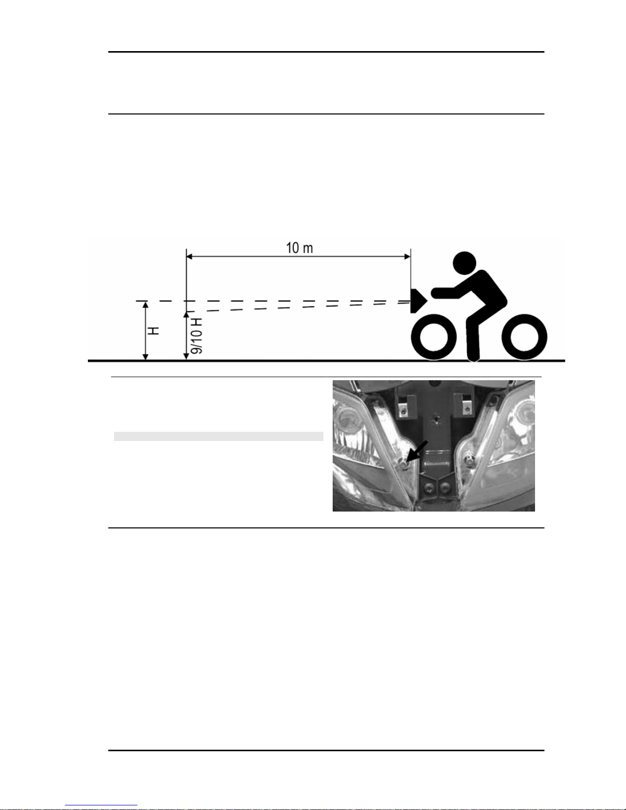
Headlight adjustment
- Place the scooter in use conditions, with tyres inflated to the prescribed pressure on flat ground at 10
m from a white screen placed in dim light.
- Make sure that the scooter's axle is perpendicular to the screen.
- Turn the headlight on and check that the limit of the light beam projected onto the screen does not
exceed 9/10 of the headlight centre height from the ground and that it is not less than 7/10.
- Otherwise, adjust the right headlight by the screw
shown in the figure, which can be accessed by removing the front shield connecting member.
N.B.
THE ABOVE PROCEDURE COMPLIES WITH THE EURO-
PEAN STANDARDS REGARDING MAXIMUM AND MINIMUM HEIGHT OF LIGHT BEAMS. REFER TO THE STATUTORY REGULATIONS IN FORCE IN EVERY COUNTRY
WHERE THE vehicle IS USED.
MSS Nexus 300 i.e. E3 ( 2008) Maintenance
MAIN - 51
Page 52

INDEX OF TOPICS
TROUBLESHOOTING TROUBL
Page 53

This section makes it possible to find what solutions to apply when troubleshooting.
For each failure, a list of the possible causes and pertaining operations is given.
Engine
Poor performance
POOR PERFORMANCE
Possible Cause Operation
Fuel pump Check the injection load relay
Excess of encrustations in the combustion chamber Descale the cylinder, the piston, the head and the valves
Incorrect timing or worn timing system elements Time the system again or replace the worn parts
Muffler obstructed Replace
Air filter blocked or dirty. Remove the sponge, wash with water and car shampoo, then
soak it in a mixture of 50% petrol and 50% specific oil. Press
with your hand without squeezing, allow it to drip dry and refit.
Oil level exceeds maximum Check for causes and fill to reach the correct level
Lack of compression: parts, cylinder and valves worn Replace the worn parts
Transmission belt worn Replace
Inefficient automatic transmission Check the rollers, the pulley movement and make sure the
drive belt is in good conditions; replace the damaged parts and
lubricate the moveable driven pulley with specific grease.
Clutch slipping Check the clutch system and/or the bell and replace if neces-
sary
Overheated valves Remove the head and the valves, grind or replace the valves
Wrong valve adjustment Adjust the valve clearance properly
Valve seat distorted Replace the head assembly
Starting difficulties
DIFFICULT STARTING
Possible Cause
Operation
Rpm too low at start-up or engine and start-up system dam-
aged
Check the starter motor, the system and the torque limiter
Incorrect valve sealing or valve adjustment Inspect the head and/or restore the correct clearance
- Engine flooded. Try starting-up with the throttle fully open. If the engine fails to
start, remove the spark plug, dry it and before refitting, make
the motor turn so as to expel the fuel excess taking care to
connect the cap to the spark plug, and this in turn to the ground.
If the fuel tank is empty, refuel and start up.
Air filter blocked or dirty. Remove the sponge, wash with water and car shampoo, then
soak it in a mixture of 50% petrol and 50% specific oil. Press
with your hand without squeezing, allow it to drip dry and refit.
Faulty spark plug or incorrect ignition advance Replace the spark plug or check the ignition circuit components
Battery flat Check the charge of the battery, if there are any sulphur marks,
replace and use the new battery following the instructions
shown in the chapter
Intake coupling cracked or clamps incorrectly tightened Replace the intake coupling and check the clamps are tight-
ened
Excessive oil consumption/Exhaust smoke
EXCESSIVE CONSUMPTION
Possible Cause
Operation
Wrong valve adjustment Adjust the valve clearance properly
Overheated valves Remove the head and the valves, grind or replace the valves
MSS Nexus 300 i.e. E3 ( 2008) Troubleshooting
TROUBL - 53
Page 54

Possible Cause Operation
Misshapen/worn valve seats Replace the head assembly
Worn cylinder, Worn or broken piston rings Replace the piston cylinder assembly or piston rings
Worn or broken piston rings or piston rings that have not been
fitted properly
Replace the piston cylinder unit or just the piston rings
Oil leaks from the couplings or from the gaskets Check and replace the gaskets or restore the coupling seal
Worn valve oil guard Replace the valve oil guard
Worn valve guides Check and replace the head unit if required
Insufficient lubrication pressure
POOR LUBRICATION PRESSURE
Possible Cause Operation
By-Pass remains open Check the By-Pass and replace if required. Carefully clean the
By-Pass area.
Oil pump with excessive clearance Perform the dimensional checks on the oil pump components
Oil filter too dirty Replace the cartridge filter
Oil level too low Restore the level adding the recommended oil type
Transmission and brakes
Clutch grabbing or performing inadequately
IRREGULAR CLUTCH PERFORMANCE OR SLIPPAGE
Possible Cause
Operation
Faulty clutch Check that there is no grease on the masses. Check that the
clutch mass contact surface with the casing is mainly in the
centre with equivalent characteristics on the three masses.
Check that the clutch casing is not scored or worn in an anom-
alous way
Insufficient braking
INEFFICIENT BRAKING SYSTEM
Possible Cause
Operation
Inefficient braking system Check the pad wear (1.5 min). Check that the brake discs are
not worn, scored or warped. Check the correct level of fluid in
the pumps and change brake fluid if necessary. Check there is
no air in the circuits; if necessary, bleed the air. Check that the
front brake calliper moves in axis with the disc.
Fluid leakage in hydraulic braking system Failing elastic fittings, plunger or brake pump seals, replace
Brake disc slack or distorted Check the brake disc screws are locked; measure the axial shift
of the disc with a dial gauge and with wheel mounted on the
scooter.
Brakes overheating
BRAKES OVERHEATING
Possible Cause
Operation
Defective sliding of pistons Replace the calliper.
Brake disc slack or distorted Check the brake disc screws are locked; use a dial gauge and
a wheel mounted on the vehicle to measure the axial shift of
the disc.
Clogged compensation holes on the pump Clean carefully and blast with compressed air
Swollen or stuck rubber gaskets Replace the calliper.
Troubleshooting MSS Nexus 300 i.e. E3 ( 2008)
TROUBL - 54
Page 55

Steering and suspensions
Heavy steering
STEERING HARDENING
Possible Cause Operation
Steering hardening Check the tightening of the top and bottom ring nuts. If irregu-
larities continue in turning the steering even after making the
above adjustments, check the rotation seats and the steering
fifth wheels.
Excessive steering play
EXCESSIVE STEERING CLEARANCE
Possible Cause Operation
Torque not conforming Check the tightening of the top and bottom ring nuts. If irregu-
larities continue in turning the steering even after making the
above adjustments, check the rotation seats and the steering
fifth wheels.
Noisy suspension
NOISY SUSPENSION
Possible Cause
Operation
Malfunctions in the suspension system
If the front suspension is noisy, check: locking tor-
ques, headstock components, inspect forks.
Suspension oil leakage
OIL LEAKAGE FROM SUSPENSION
Possible Cause
Operation
Seal fault or breakage Replace the shock absorber
MSS Nexus 300 i.e. E3 ( 2008) Troubleshooting
TROUBL - 55
Page 56

INDEX OF TOPICS
ELECTRICAL SYSTEM ELE SYS
Page 57
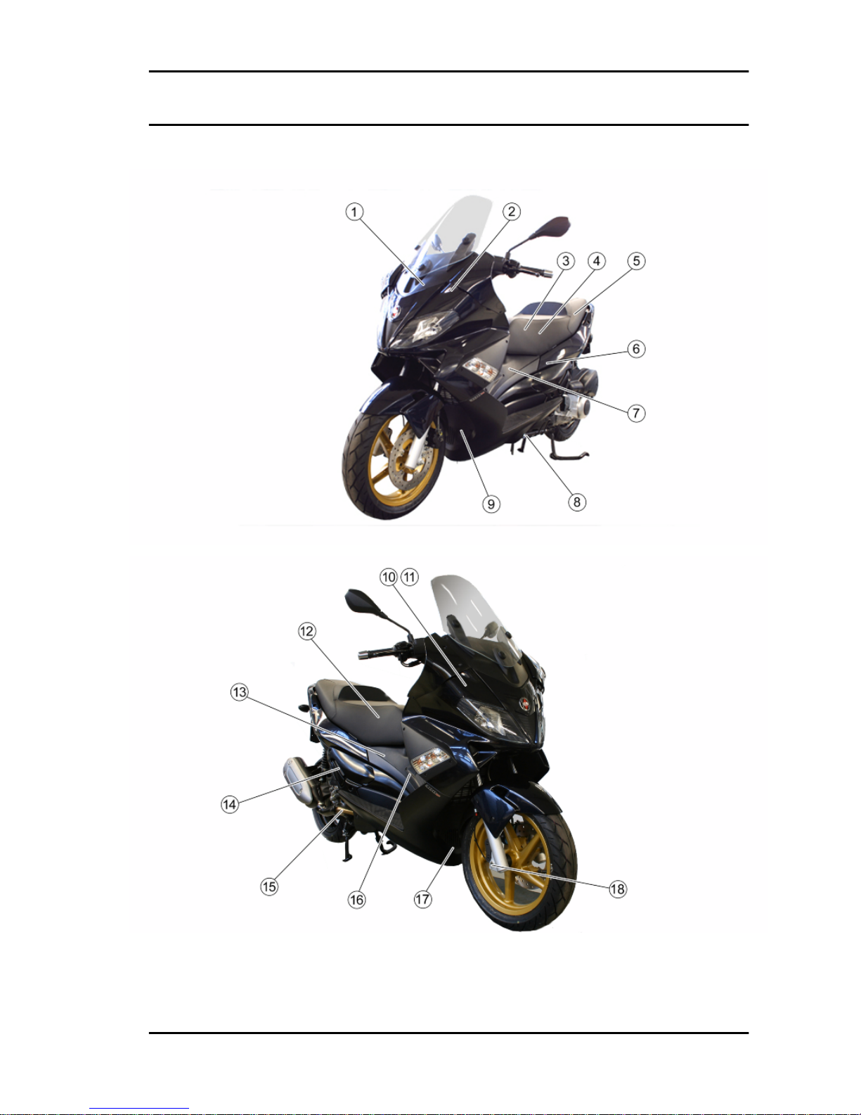
Components arrangement
MSS Nexus 300 i.e. E3 ( 2008) Electrical system
ELE SYS - 57
Page 58

1. Remote controls
Remove the legshield to reach it.
A. Electric fan remote control
B. High-beam light remote control
C. Injection load remote control
2. Electric control management device
Remove the legshield to reach it.
3. Main fuses
To reach them, remove the battery cover placed in the helmet compartment.
4. Injection ECU
To reach it, remove the inspection compartment
placed in the helmet compartment.
5. Auxiliary fuses
Located in the helmet compartment.
6. Starter motor
To reach it, remove the helmet compartment.
Electrical system MSS Nexus 300 i.e. E3 ( 2008)
ELE SYS - 58
Page 59

7. Start-up remote control
To reach it, remove the central chassis cover.
8. Stand button
Remove the left footrest to reach them.
9. Horn
To reach it, remove the lower cover.
10-11. Key switch/Immobilizer aerial
Remove the shield back plate to reach them.
12. Battery
To reach it, remove the battery cover placed in the helmet compartment.
MSS Nexus 300 i.e. E3 ( 2008) Electrical system
ELE SYS - 59
Page 60

13. HV coil
Remove the right side fairing to reach them.
14. Magneto flywheel
The connector is located near the fuel pump. To
reach it, remove the central chassis cover.
15. Oil pressure sensor
On the engine, on the right-hand side of the vehicle.
16. Fuel level transmitter
To reach it, remove the central chassis cover. The
transmitter is integrated to the fuel pump.
Electrical system MSS Nexus 300 i.e. E3 ( 2008)
ELE SYS - 60
Page 61

17. Voltage regulator
To reach it, remove the lower cover.
18.Wheel turning sensor
In the front wheel, on the right-hand side.
Ground points
A. Ground points on the chassis
To reach them, remove the right footrest.
B. Ground point on the engine
To reach it, remove the inspection compartment
placed in the helmet compartment.
MSS Nexus 300 i.e. E3 ( 2008) Electrical system
ELE SYS - 61
Page 62

Checks and inspections
This section is devoted to the checks on the electrical system components.
Immobiliser
The electronic ignition system is controlled by the control unit with the integrated Immobilizer system.
The immobilizer is an anti-theft system that allows the vehicle to be operated only when it is started with
coded keys recognised by the control unit. The code is integrated in a transponder in the key block.
This allows the driver clear operation without having to do anything other than just turning the key. The
Immobilizer system consists of the following components:
- electronic control unit
- immobilizer aerial
- master key with incorporated transponder (red key)
- service key with incorporated transponder (black key)
- HV coil
- diagnosis LED
The diagnosis LED also works as a theft-deterrent blinker. This function is activated every time the
ignition switch is turned to the "OFF" position, or the emergency stop switch is turned to the "OFF"
position. It remains activated for 48 hours in order not to affect the battery charge. When the ignition
switch is turned to the "ON" position, the theft-deterrent blinker function is deactivated. Subsequently,
a flash confirms the switching to the "ON" status. The duration of the flash depends on the programming
of the electronic control unit If the LED is off regardless of the position of the ignition-key switch and/or
the instrument panel is not initiated, check if:
•
there is battery voltage
•
fuses 1,5,7,8 are in working order
•
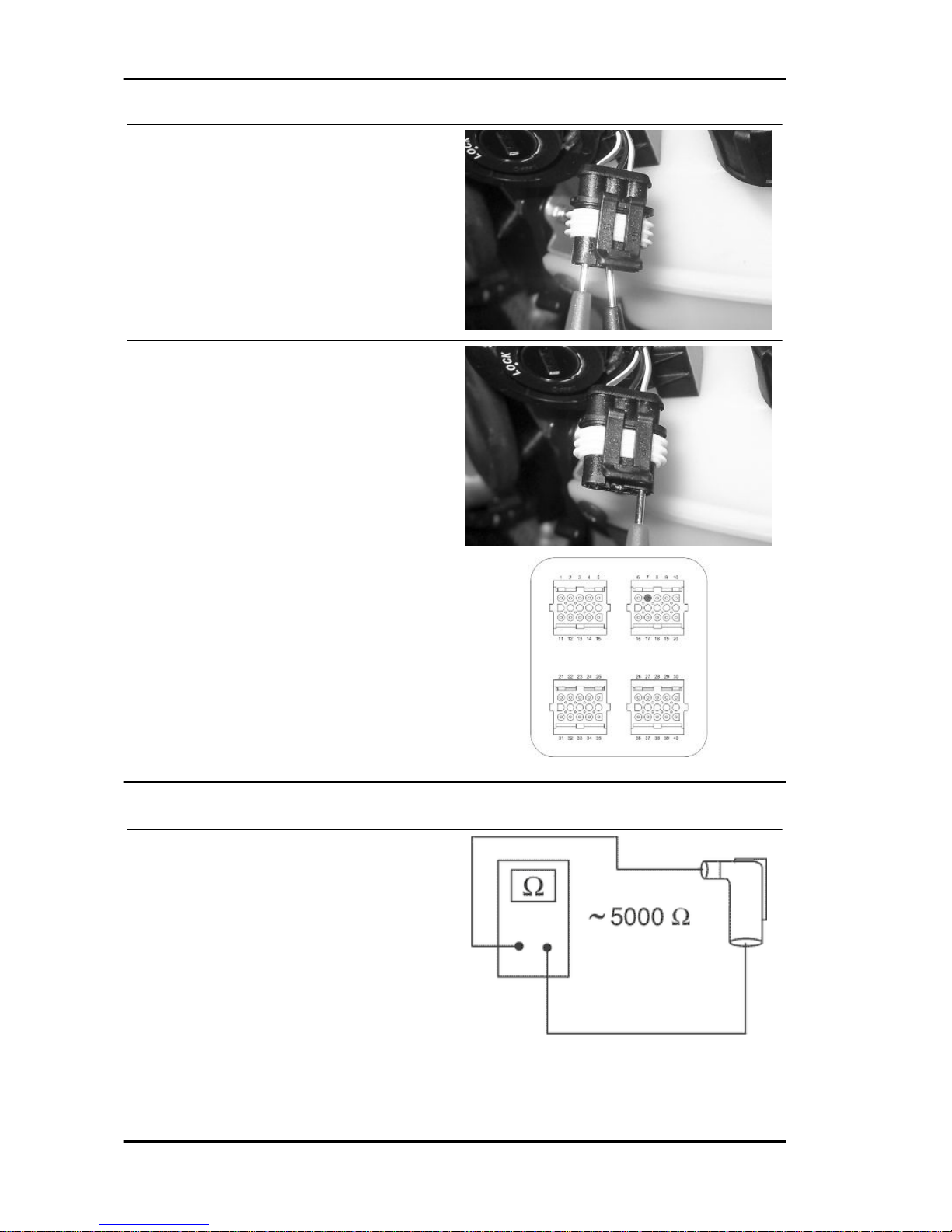
there is power to the control unit as specified below:
Remove the connector support bracket shown in the photograph and disconnect the connector from
the control unit. Check the following conditions:
With the key switch set to OFF:
•
if there is battery voltage between terminals 6-26 and terminal 6-chassis
ground (fixed power supply). If there is
no voltage check that fuse 1 and its cable are in working order.
Electrical system MSS Nexus 300 i.e. E3 ( 2008)
ELE SYS - 62
Page 63

With the key switch in the OFF position:
•
there is battery voltage between terminals 5-26 and terminal 5-frame earth
(fixed power supply). If there is no voltage, check the key switch contacts,
that fuses No. 5 and 7 plus their cables
are in working order.
•
There is continuity between terminals
12-18 and the emergency cut-out
switch is set to "RUN" and the side
stand folded up. If there is no continuity
check the contacts of the latter.
After removing the shield back plate, remove the
electrical connection from the aerial as shown in
the photograph.
Remove the protective base from the connector.
MSS Nexus 300 i.e. E3 ( 2008) Electrical system
ELE SYS - 63
Page 64
With the ignition key switch set to ON, check if
there is battery voltage between the White-Black
and Black cables.
With MIU connector disconnected, check the continuity between the Orange-White cable and pin 7
of the interface wiring .
Specific tooling
020481Y Control unit interface wiring
020331Y Digital multimeter
Virgin circuit
When the ignition system is not encrypted, any key
will start the engine but limited to 2000 rpm. The
keys can only be recognised if the control unit has
been programmed properly. The data storage procedure for a previously not programmed control
unit provides for the recognition of the master as
the first key to be stored to memory: this becomes
particularly important because it is the only key
that enables the control unit to be wiped clean and
reprogrammed for the memorisation of the service
Electrical system MSS Nexus 300 i.e. E3 ( 2008)
ELE SYS - 64
Page 65

keys. The master and service keys must be used
to code the system as follows:
- Insert the Master key, turn it to «ON» and keep
this position for two seconds (limit values 1 to 3
seconds).
- Insert the service key and turn it to «ON» for 2
seconds.
- If you have copies of the key, repeat the operation
with each key.
- Insert the MASTER key again and turn it to «ON»
for 2 seconds.
The maximum time to change keys is 10 seconds.
A maximum of 7 service keys can be programmed
at one time.
It is essential to adhere to the times and the procedure. If you do not, start again from the beginning. Once the system has been programmed, the
master key transponder is strictly matched with the
control unit. With this link established, it is now
possible to encode new service keys, in the event
of losses, replacements, etc. Each new programming deletes the previous one so, in order to add
or eliminate keys, you must repeat the procedure
using all the keys you intend to keep using. If a
service key becomes uncoded, the efficiency of
the high voltage circuit shielding must be thoroughly inspected: In any case it is advisable to use
resistive spark plugs.
Characteristic
MASTER key:
RED KEY
SERVICE key.
BLACK KEY
MSS Nexus 300 i.e. E3 ( 2008) Electrical system
ELE SYS - 65
Page 66
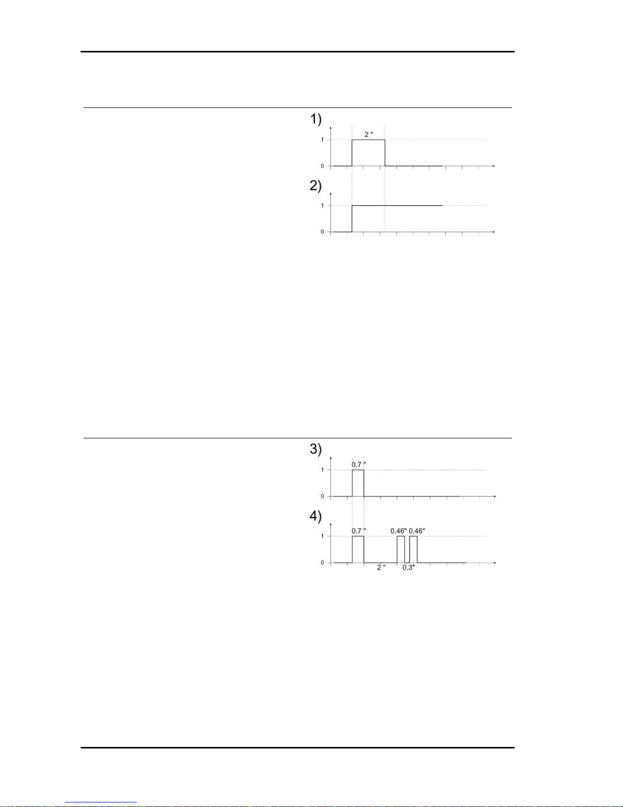
Diagnostic codes
The immobiliser system is tested each time the ignition-key switch is turned from OFF to ON. During
this diagnosis phase a number of control unit statuses can be seen and various light codes displayed. Regardless of the code transmitted, if at
the end of the diagnosis the led remains off permanently, the ignition is enabled. If, however, the
led remains on permanently, it means the ignition
is inhibited:
1. Previously unused control unit - key inserted: a single 2 second flash is displayed, after
which the LED remains off permanently. The keys
can be stored to memory, the vehicle can be started but with a limitation imposed on the number of
revs.
2. Previously unused control unit - transponder absent or cannot be used: The LED is per-
manently ON; in this condition, no operations are
possible, including starting of the vehicle.
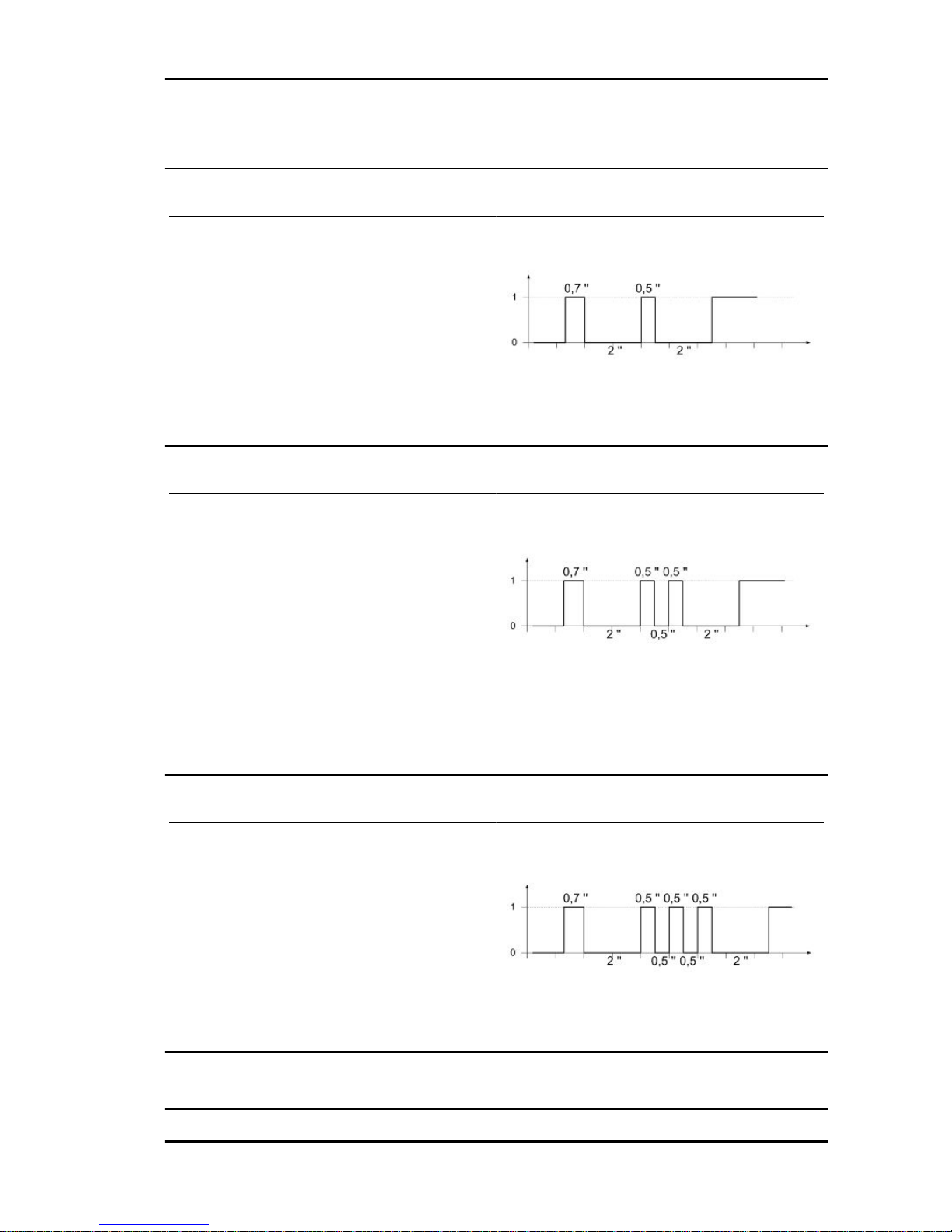
3. Programmed control unit - the service key in
(normal condition of use): a single 0.7-second
flash is displayed, after which the LED remains off
steadily. The engine can be started.
4. Programmed control unit - Master key in: a
0.7 sec. flash is displayed followed by the LED remaining off for 2 sec. and then by short 0.46 sec.
flashes the same number of times as there are
keys stored in the memory including the Master
key. When the diagnosis has been completed, the
LED remains permanently OFF. The engine can
be started.
5. Programmed control unit - fault detected: a light code is displayed according to the fault detected,
after which the LED remains on steadily. The engine cannot be started. The codes that can be transmitted are:
•
Code 1 flash
•
2-flash code
Electrical system MSS Nexus 300 i.e. E3 ( 2008)
ELE SYS - 66
Page 67
•
3-flash code
Diagnostic code - 1 flash
The one-flash code indicates a system where the
serial line is not present or is not detected. Check
the Immobilizer aerial wiring and change it if necessary.
Diagnostic code - 2 flashes
A two-flash code shows a system where the control unit does not show the transponder signal. This
might depend on the inefficiency of the immobiliser
aerial or the transponder.
Turn the switch to ON using several keys: if the
code is repeated even with the Master key, check
the aerial wiring and change it if necessary. If this
is not the case, replace the defective key and/or
reprogram the control unit. Replace the control unit
if the problem continues.
Diagnostic code - 3 flashes
A three-flash code indicates a system where the
control unit does not recognise the key. Turn the
switch to ON using several keys: if the error code
is repeated even with the Master key, replace the
control unit. If this is not the case, perform a reprogramming.
Ignition circuit
MSS Nexus 300 i.e. E3 ( 2008) Electrical system
ELE SYS - 67
Page 68
No spark plug
WARNING
ALL CONTINUITY TESTS MUST BE CARRIED OUT WITH THE CORRESPONDING CONNECTORS
DISCONNECTED.
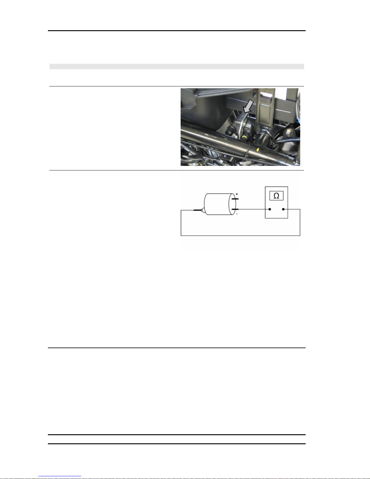
HV coil primary resistance value:
Disconnect the connector of the HV coil and measure the resistance between the two terminals.
Characteristic
HV coil resistance primary value:
~ 0.9 Ω
HV coil secondary resistance value:
1) Disconnect the HV cable from the spark plug
and measure the resistance between the spark
plug cap and the HV coil negative terminal.
2)Disconnect the spark plug cap from the HV cable
and measure the resistance between the HV cable
end and the HV coil negative terminal (see figure).
3) Measure the resistance between the 2 ends of
the spark plug cap.
Characteristic
HV coil secondary resistance value with spark
plug cap
~ 8.4 kΩ
HV coil secondary resistance value:
~ 3.4 kΩ
Spark plug cap resistance value
~ 5 kΩ
Battery recharge circuit
The recharge system is provided with a three phase alternator with permanent flywheel.
The alternator is directly connected to the voltage regulator.
This, in its turn, is connected directly to the ground and the battery positive terminal passing through
the 30A protective fuse.
The three- phase generator provides good recharge power and at low revs, a good compromise is
achieved between generated power and idle stability.
Electrical system MSS Nexus 300 i.e. E3 ( 2008)
ELE SYS - 68
Page 69
Stator check
Stator winding check-up
WARNING
THIS CHECK-UP CAN BE MADE WITH THE STATOR PROPERLY INSTALLED.
1) Remove the central chassis cover.
2) Disconnect the connectors between stator and regulator with the three yellow cables.
3) Measure the resistance between each of the yellow terminals and the other two.
Electric characteristic
Resistance:
0.2 - 1 Ω
4) Check that there is insulation between the each
yellow cable and the ground.
5) If values are incorrect, replace the stator.
Recharge system voltage check
Look for any leakage
1) Access the battery by removing its cover under the saddle.
2) Check that the battery does not show signs of losing fluid before checking the output voltage.
3) Turn the ignition key to position OFF, connect the terminals of the tester between the negative pole
(-) of the battery and the black cable and only then disconnect the black cable from the negative pole
(-) of the battery.
4) With ignition key still at OFF, the reading detected by the ammeter must be ≤ 0.5 mA.
Check the charging current
WARNING
BEFORE CARRYING OUT THE CHECK, MAKE SURE THAT THE BATTERY IS IN GOOD WORKING ORDER.
1) Place the vehicle on its centre stand
2) With the battery correctly connected to the circuit, place the tester terminals between the battery
terminals..
3) Turn on the engine, increase the engine rpm and, at the same time, measure the voltage.
Electric characteristic
Voltage ranging between 14.0 and 15.0V at 5000 rpm.
Maximum current output check.
MSS Nexus 300 i.e. E3 ( 2008) Electrical system
ELE SYS - 69
Page 70
- With the engine off and the panel at «ON» with the lights on, allow the battery voltage to stop at 12V.
- Connect ammeter pliers to the 2 recharge positive poles in output from the regulator.
- Start the engine and rev it up to a high engine speed while reading the value on the pincer.
With an efficient battery a value must be detected: > 20A
VOLTAGE REGULATOR/RECTIFIER
Specification Desc./Quantity
Type Non-adjustable three-phase transistor
Voltage 14 ÷ 15V at 5000 rpm with lights off
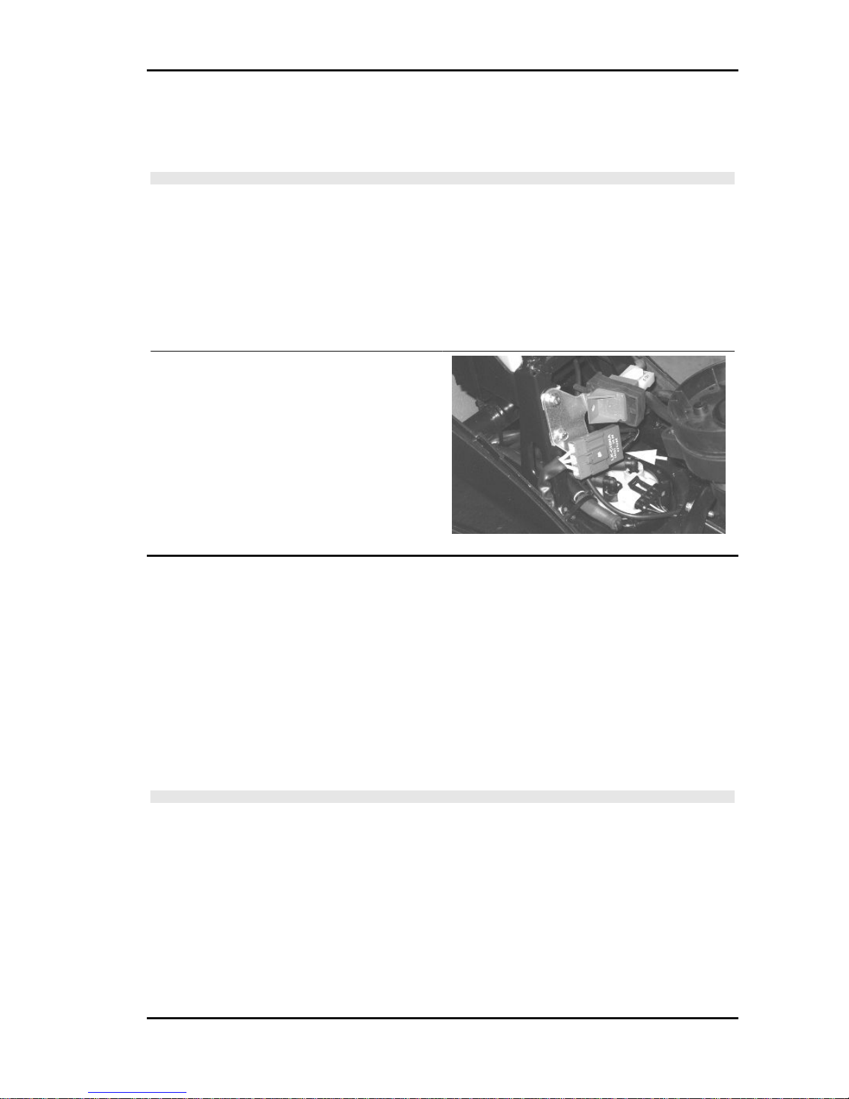
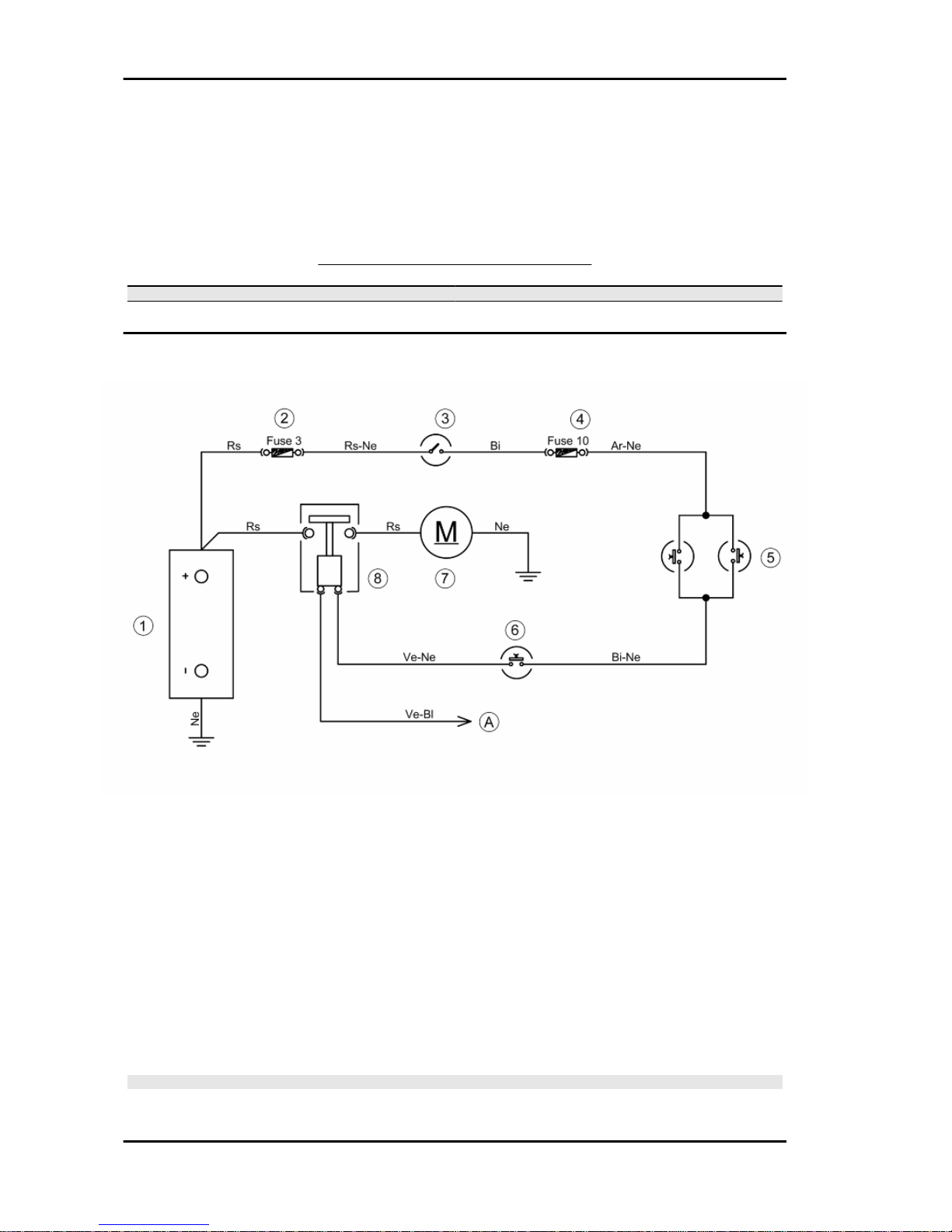
Starter motor
KEY
1. Battery
2. Fuse No. 3
3. Key switch contacts
4. Fuse No. 10
5. Stop buttons
6. Starter button
7. Starter motor
8. Start-up remote control
A. To injection ECU
WARNING
ALL CONTINUITY TESTS MUST BE CARRIED OUT WITH THE CORRESPONDING CONNECTORS
DISCONNECTED.
Electrical system MSS Nexus 300 i.e. E3 ( 2008)
ELE SYS - 70
Page 71
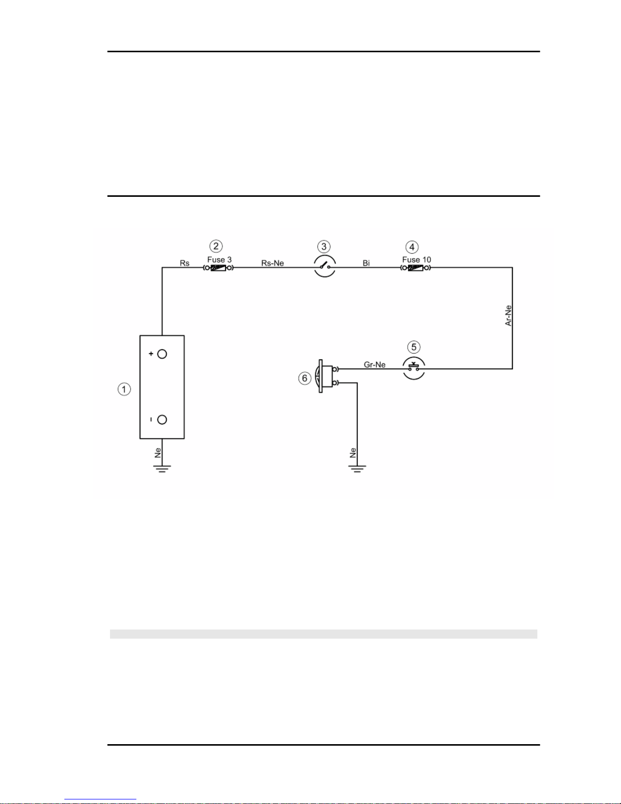
1) Check fuses No. 3 and 10, and the key switch contacts.
2) Check the contacts of the stop buttons and the starter button.
3) Check the start-up remote control switch.
4) Check wiring continuity between the Green-Blue cable that connects the starter remote control to
the injection electronic control unit (pin 24).
5) Check the starter motor ground connection.
Horn control
KEY
1. Battery
2. Fuse No. 3
3. Key switch contacts
4. Fuse No. 10
5. Horn button
6. Horn
WARNING
ALL CONTINUITY TESTS MUST BE CARRIED OUT WITH THE CORRESPONDING CONNECTORS
DISCONNECTED.
1) Check fuses No. 3 and 10, and the key switch contacts.
2) Check the horn button contacts.
3) Check wiring continuity.
4) Check the horn ground connection.
MSS Nexus 300 i.e. E3 ( 2008) Electrical system
ELE SYS - 71
Page 72
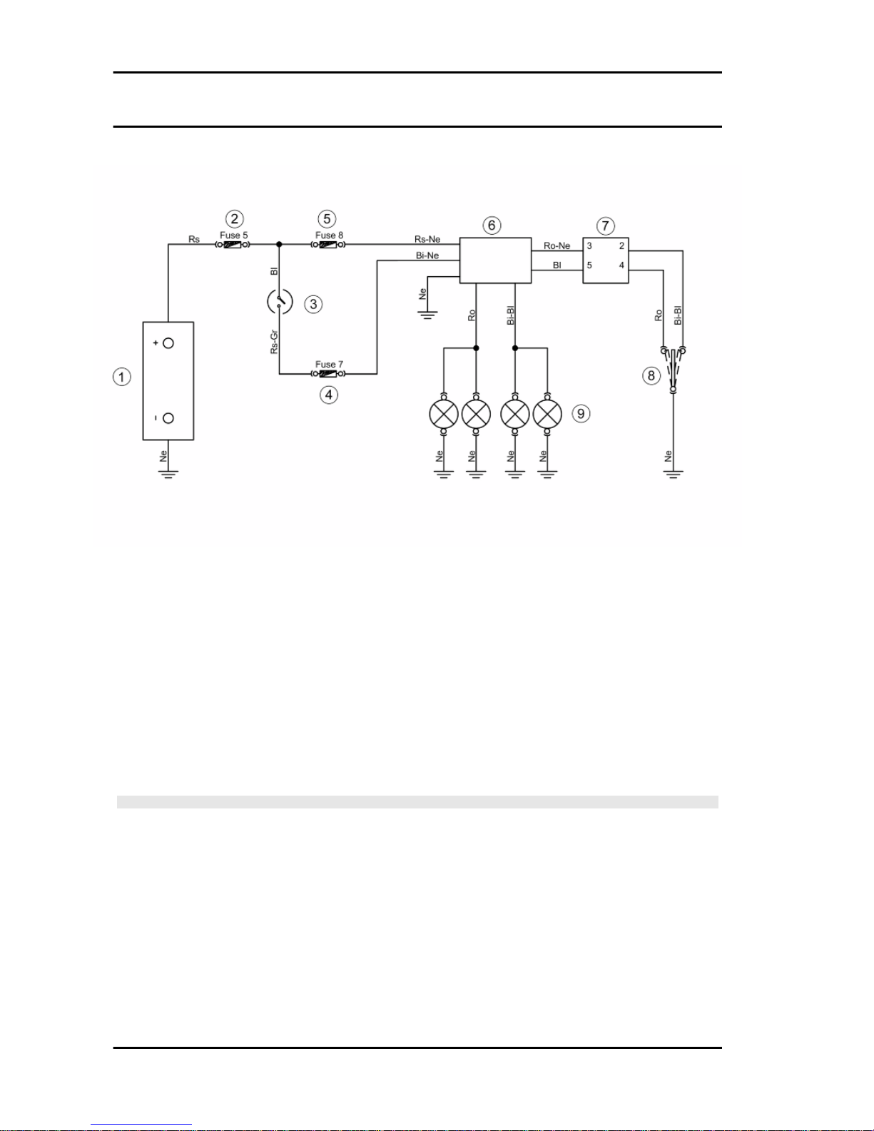
Turn signals system check
KEY
1. Battery
2. Fuse No. 5
3. Key switch contacts
4. Fuse No. 7
5. Fuse No. 8
6. Turn indicator control device
7. Electric control management device
8. Turn indicator switch
9. Turn indicator bulbs
WARNING
ALL CONTINUITY TESTS MUST BE CARRIED OUT WITH THE CORRESPONDING CONNECTORS
DISCONNECTED.
1) Check that bulbs operate properly.
2) Check fuses No. 5; 7; 8 and the key switch contacts.
3) Check if there is voltage between the Red-Black cable and the Black cable of the turn indicator control
device or check wiring continuity.
3) With the key switch set to «ON», check again between the White-Black and the Black cables.
4) Check the turn indicator switch contacts.
5) Check continuity between the Red- Black cable (pin 3) and the White-Blue cable (pin 2) of the electric
control device.
Electrical system MSS Nexus 300 i.e. E3 ( 2008)
ELE SYS - 72
Page 73
6) Repeat the check between the Blue cable (pin 5) and the Pink cable (pin 4).
7) Use the turn indicator control device to check bulb wiring continuity .
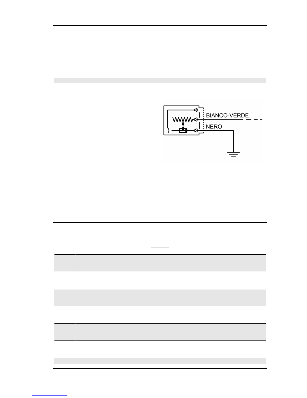
level indicators
WARNING
ALL CONTINUITY TESTS MUST BE CARRIED OUT WITH THE CORRESPONDING CONNECTORS
DISCONNECTED.
If faults are detected:
1) With a multimeter, check resistance values between the White-Green cable and the Black cable
of the fuel level transmitter under different conditions.
2) If the transmitter operates correctly but the indication on the instrument panel is not exact,
check that the cable harnesses between them are
not interrupted.
Electric characteristic
Resistance value when the tank is full
<= 7 Ω
Resistance value when the tank is empty
90 +13/-3 Ω
Lights list
BULBS
Specification
Desc./Quantity
1 High/low beam light bulb
Type: Halogen (H7)
Power: 12V - 55W
Quantity: 2
2 Front headlights bulb
Type: Incandescent (W2.1 x 9.5 D)
Power: 12V - 5W
Quantity: 2
3 Rear turn indicator bulbs
Type: Incandescent (BAU 155 )
Power: 12V-10W
Quantity: 2
4 Front turn indicator bulbs
Type: Incandescent (BAU 155 )
Power: 12V-10W
Quantity: 2
5 Tail light and stop light bulb
Type: Incandescent (W2.1 x 9.5 D)
Power: 12V - 21/5W
Quantity: 1
6 License plate light bulb
Type: Incandescent (W2.1 x 9.5 D)
Power: 12V - 5W
Quantity: 1
7 Helmet compartment light bulb
Type: Incandescent (SV 8.5)
MSS Nexus 300 i.e. E3 ( 2008) Electrical system
ELE SYS - 73
Page 74

Specification Desc./Quantity
Power: 12V - 5W
Quantity: 1
Fuses
The electric system is fitted with 2 fuse boxes:
1. Fuse box «A» 6 fuses located in the helmet
compartment near the battery.
2. Fuse box «B» 6 fuses located in the helmet
compartment near the plug socket.
Replace fuses using adequate pliers supplied in
the tool kit.
The chart shows the position and characteristics
of the fuses in the vehicle.
CAUTION
BEFORE REPLACING A BLOWN FUSE, FIND AND SOLVE
THE FAILURE THAT CAUSED IT TO BLOW. NEVER TRY
TO REPLACE THE FUSE WITH ANY OTHER MATERIAL
(E.G., A PIECE OF ELECTRIC WIRE).
FUSE BOX A
Specification
Desc./Quantity
1 Fuse No. 1
Capacity:7.5 A
Protected circuits: Injection ECU supply
2 Fuse No. 2
Capacity:10 A
Protected circuits:HV coil - Fuel injector -
Fuel pump
3 Fuse No. 3
Capacity: 15A
Protected circuits: Lines protected by fuses
No. 9; 10; 11; 12.
4 Fuse No. 4
Capacity:15A
Protected circuits: Radiator electric fan
5 Fuse No. 5
Capacity:15A
Protected circuits: Lines protected by fuses
No. 7 and 8; 12V 180W Socket, Helmet com-
partment bulb
6 Fuse No. 6
Capacity:30 A
Protected circuits:Recharge circuit
Electrical system MSS Nexus 300 i.e. E3 ( 2008)
ELE SYS - 74
Page 75

CAUTION
BEFORE REPLACING A BLOWN FUSE, FIND AND SOLVE
THE FAILURE THAT CAUSED IT TO BLOW. NEVER TRY
TO REPLACE THE FUSE WITH ANY OTHER MATERIAL
(E.G., A PIECE OF ELECTRIC WIRE).
FUSE BOX B
Specification
Desc./Quantity
1 Fuse No. 7
Capacity:7.5 A
Protected circuits: Digital instrument panel,
Turn indicator bulbs, Radiator electric fan re-
mote control, ECU remote control, Immobil-
izer, Antitheft device pre-installation
2 Fuse No. 8
Capacity:7.5 A
Protected circuits: Digital instrument panel,
Antitheft device pre-installation
3 Fuse No. 9
Capacity:7.5 A
Protected circuits:Analogue rpm indicator
and digital instrument panel, tail lights, instru-
ment panel lights
4 Fuse No. 10
Capacity:7.5 A
Protected circuits: Stop bulb, Engine start-
up circuit, Horn
5 Fuse No. 11
Capacity: 7.5 A
Protected circuits: High-beam light bulb,
High-beam remote control, High-beam warn-
ing light
6 Fuse No. 12
Capacity:7.5 A
Protected circuits: Low-beam light bulb
MSS Nexus 300 i.e. E3 ( 2008) Electrical system
ELE SYS - 75
Page 76

Dashboard
The digital display has two service symbols:
SERVICE:
The lamp should come on after reaching 1000 km,
then every 10,000 km or 1 year after the last activation.
BELT:
This lamp should come on and flash every 10,000
km.
•
Press buttons "MODE" and "ODO/SET" simultaneously at the moment you turn the key to
"ON" for more than 3 seconds: The "BELT" symbol starts to flash.
•
Pressing the button "MODE" for less than 1 second displays the symbols in turn. The selected symbol remains lit.
•
Pressing button "MODE" for longer than 3 seconds resets the kilometre reading for the
symbol selected, in "SERVICE" mode the date is also reset.
N.B.
•
AT THE MOMENT THE DATE IS RESET, THE "SERVICE" SYMBOL IS ACTIVATED
AGAIN.
•
PERFORM THE RESET PROCEDURE ONLY AT THE MOMENT OF DELIVERY OF THE
SCOOTER TO THE CUSTOMER IN ORDER THAT THIS SYMBOL SIGNALS THE NEED
FOR THE FIRST SERVICE IN RELATION TO THE DISTANCE TRAVELLED AND THE
TIME SINCE THE ACTIVATION.
The scooter has an instrument panel subdivided
into 3 sections: Digital instrument with LCD and
analogue speedometer, analogue rev counter and
warning light group.
• Warning light group
The warning light group includes:
- Warning light preparation
- Tail light and low-beam warning light (green)
- High-beam warning light (blue)
Electrical system MSS Nexus 300 i.e. E3 ( 2008)
ELE SYS - 76
Page 77

- Warning light preparation
• Digital instrument
The digital section provides the displays of:
- Injection warning light (amber)
- Low fuel warning light (amber)
- Oil pressure warning light (red)
- Turn signal warning light (green)
- Immobilizer LED (red)
The digital section of the instrument panel is completed by a liquid crystal display and 3 control
buttons (MODE - CLOCK - ODO/SET).
- The LCD panel provides a 5-digit display for the visualisation of:
• Total kilometres
• Trip kilometres
• Clock
N.B.
IT IS POSSIBLE TO CHANGE THE DISPLAY TO KM OR MILES BY PRESSING THE BUTTONS
"MODE" AND "CLOCK" SIMULTANEOUSLY FOR LONGER THAN 3 SECONDS AT THE MOMENT
YOU TURN THE KEY TO POSITION "ON". THE WORD "SET" WILL BE DISPLAYED.
- Pushing the "MODE" button for less than a second displays the following function sequence:
1. Average speed
The word "MEAN" appears together with km/h or mph.
The value is calculated on the basis of the trip kilometre reading.
2. Maximum speed
The word "MAX" appears together with km/h or mph.
The value is calculated on the basis of the trip kilometre reading.
3. Average consumption
The fuel symbol, the word "MEAN" and km/h or mph appear.
The value is calculated on the basis of the trip kilometre reading.
4. Momentary consumption
The fuel symbol and km/h or mph appear.
5. Range
The fuel icon appears.
MSS Nexus 300 i.e. E3 ( 2008) Electrical system
ELE SYS - 77
Page 78

If the range drops below 40 km, the symbol appears automatically and flashes for 60 seconds.
When the low fuel warning light comes on permanently, dashes appear instead of the range value.
6. Battery voltage
The battery symbol appears
Pressing button "MODE" for longer than 3 seconds returns you to function "1" of the sequence (average
speed).
- The display also contains the symbols:
BELT:
Indicates the need to replace the transmission
belt.
This lamp should come on and flash every 10,000
km.
SERVICE:
Indicates the need to carry out the scheduled
maintenance operations.
The lamp should come on after reaching 1000 km
or 1 year after initial activation, then every 10,000
km or 1 year after the last activation.
WARNING
THE SCOOTER SHOULD BE SERVICED IN ANY CASE AT
THE KILOMETRE INTERVALS INDICATED IN THE OPERATING AND MAINTENANCE MANUAL; DO NOT RELY ON
THE SERVICE DISPLAY THAT APPEARS ON THE INSTRUMENT PANEL.
Data check function
Setting the clock.
To set the clock, press the button "CLOCK" for more than 3 seconds.
The figures showing the hours start to flash.
Set the hours with the button "ODO/SET".
Press button "CLOCK" again and the figures showing the minutes start to flash.
Set the minutes with the «ODO/SET» button.
Press the «CLOCK» button again to start the clock moving normally.
During the reset process, not pressing any buttons for 8 seconds ends the process and the display will
automatically show the modified time.
Setting the date.
Set the "DATE" using the "CLOCK".
Electrical system MSS Nexus 300 i.e. E3 ( 2008)
ELE SYS - 78
Page 79

If the button "CLOCK" is pressed for longer than 3 seconds, the figures showing the days start to flash.
Set the day with the «ODO/SET» button.
Press the "CLOCK" button again; the numbers showing the months start to flash.
Set the month with the "ODO/SET" button.
Press the "CLOCK" button again; the numbers showing the years start to flash.
Set the year with the "ODO/SET" button.
Press the «CLOCK» button again to start the clock moving normally.
During the reset process, not pressing any buttons for 8 seconds ends the process and the display will
automatically show the modified date.
Sealed battery
Commissioning sealed batteries
If the vehicle is provided with a sealed battery, the only maintenance required is the check of its charge
and recharging, if necessary.
These operations should be carried out before delivering the vehicle, and on a six-month basis while
the vehicle is stored in open circuit.
Besides, upon pre-delivery it is therefore necessary to check the battery charge and recharge it, if
required, before storing the vehicle and, afterwards, every six months.
INSTRUCTIONS FOR THE BATTERY REFRESH AFTER OPEN-CIRCUIT STORAGE
1) Voltage check
Before installing the battery on the vehicle, check the open circuit voltage with a regular tester.
- If voltage exceeds 12.60 V, the battery can be installed without any renewal recharge.
- If voltage is below 12.60 V, a renewal recharge is required as explained in 2).
2) Constant voltage battery charge mode
- Constant voltage charge equal to 14.40 ÷ 14.70V
-Initial charge voltage equal to 0.3 ÷ 0.5 for Nominal capacity
- Charge time:
10 to 12 h recommended
Minimum 6 h
Maximum 24 h
3) Constant current battery charge mode
-Charge current equal to 1/10 of the nominal capacity of the battery
- Charge time: 5 h
Specific tooling
020333Y Single battery charger
020334Y Multiple battery charger
Cleaning the battery
MSS Nexus 300 i.e. E3 ( 2008) Electrical system
ELE SYS - 79
Page 80

The battery should always be kept clean, especially on its top side, and the terminals should be coated
with Vaseline.
CAUTION
NEVER USE FUSES WITH A CAPACITY HIGHER THAN THE RECOMMENDED CAPACITY. USING
A FUSE OF UNSUITABLE RATING MAY SERIOUSLY DAMAGE THE VEHICLE OR EVEN CAUSE
A FIRE.
CAUTION
CHARGE THE BATTERY BEFORE USE TO ENSURE OPTIMUM PERFORMANCE. FAILURE TO
CHARGE THE BATTERY ADEQUATELY BEFORE BEING PUT INTO OPERATION WILL LEAD TO
A PREMATURE FAILURE OF THE BATTERY.
If the scooter is not used for a given time (1 month or more) it will be necessary to periodically recharge
the battery.
The battery runs down completely in the course of three months. If it is necessary to refit the battery in
the vehicle, be careful not to reverse the connections, remembering that the ground wire (black) marked
(-) must be connected to the negative clamp while the other two red wires marked (+) must be connected to the clamp marked with the + positive sign.
Dry-charge battery
COMMISSIONING A NEW DRY-CHARGED BATTERY
- Remove the battery air pipe stop cap and each single cell cap.
- Fill the battery with electrolyte of 1.270+/-0.01 kg/l density (corresponding to 31+/-1 Bé) with an ambient temperature not below 15°C, until it reaches the upper level indicated on the block.
- Tilt the battery slightly to remove any air bubbles formed during filling.
- Place the caps on each single cell filling hole without screwing them and leave the battery to rest.
During this stage, the battery is subjected to a gasification phenomenon and temperature increases.
- Let it rest until it reaches ambient temperature (this stage can take up to 60 minutes).
- Tilt the battery slightly to facilitate the elimination of any gas bubbles present inside; restore the level
using the same filling electrolyte
Note: This is the last time that electrolyte can be added. Future top-ups should be done only with distilled
water;
- Before 24 hours elapse, recharge the battery following these steps:
- Connect the battery charger terminals observing the correct polarity;
- Wit the battery charger drw. 020333Y and/or drw. 020334Y operate the battery charger control by
selecting the position corresponding to that capacity;
- Otherwise, charge the battery with direct current equal to 1/10 of rated capacity (e.g. for a battery with
a 9Ah rated capacity, the charging current should be 0.9-1.0A) for approximately a 4-6 hour charge.
Note: Batteries that have been stored for a long time may take a longer charging time. The battery
chargers drw. 020333Y and drw. 020334Y have an automatic protection which interrupts the recharge
after 12 hours to avoid battery harmful heating. In this case, a green LED turns on to indicate the
activation of the safety system and not the end of the charge.
Electrical system MSS Nexus 300 i.e. E3 ( 2008)
ELE SYS - 80
Page 81
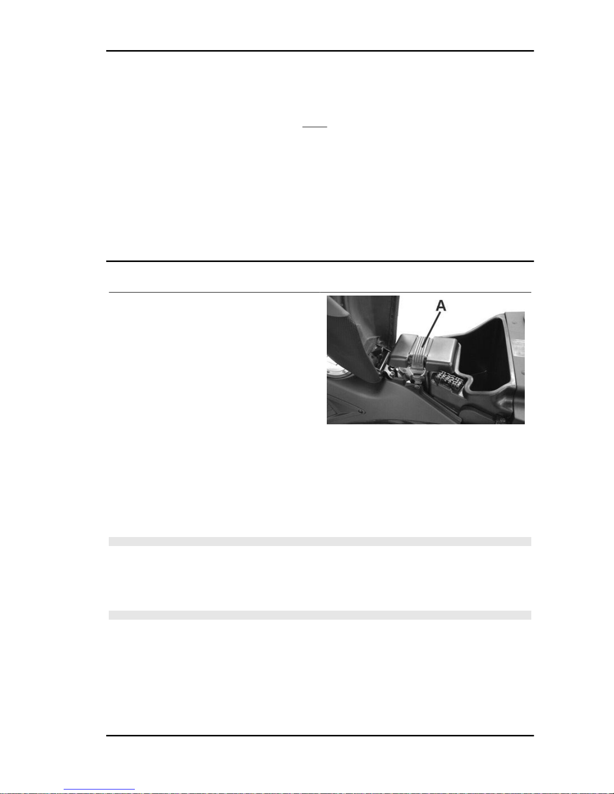
- Let the open circuit battery rest for approximately 4-6 hours; then check the off-load voltage using a
standard tester.
- If the open-circuit voltage is higher or equal to 12.6V, the battery is charged adequately. Slightly shake
or tilt the battery to eliminate any air bubbles formed during recharging.
- Check the electrolyte levels again, fill them with distilled water up to the upper level line if necessary,
clean battery properly, close each single cell cap tightly and install it on the vehicle.
- If the voltage indicated is low, charge the battery another 4-6 hours in the way described above.
Note: With the battery charger drw. 020334Y, it is possible to check the battery charge level with the
Check function. The value indicated on the display must be higher than the value indicated on the chart;
otherwise, recharge the battery again in the same way indicated above.
Battery installation
To access the battery, proceed as follows:
1. Place the scooter on its centre stand;
2. Open the saddle following above instructions,
see «Saddle» section;
3. Remove the piston ring «A» and take off the
battery cover.
The battery is the electrical device that requires the
most frequent inspections and diligent maintenance. The most relevant maintenance rules to be
observed are as follows:
Electric characteristic
Battery
12V-14Ah
- Insert the battery by connecting the battery breather tube as shown in the photograph.
N.B.
IN ORDER TO FIT THE CABLES ON THE BATTERY TERMINALS CORRECTLY, REST THE LOWER END OF THE TERMINAL SIDE OF THE BATTERY ON THE EDGE OF THE BATTERY WELL.
- Using the screwdriver, tighten up the battery terminal cables as far as they will go, placing the special
Grover washer between the screw head and the cable terminal.
N.B.
DO NOT USE WRENCHES TO TIGHTEN UP THE SCREWS FOR FIXING THE TERMINALS TO THE
BATTERY TERMINALS
MSS Nexus 300 i.e. E3 ( 2008) Electrical system
ELE SYS - 81
Page 82

- Refit the battery cover
Make sure that the terminals are connected correctly. When a new battery is installed, the correct time
and date must be reset on the digital instrument panel («Clock» and «MODE button» section).
CAUTION
DO NOT REVERSE THE POLARITY: RISK OF SHORT CIRCUIT AND DAMAGE TO THE ELECTRICAL SYSTEM.
The electrolyte level, which should be checked regularly, must always be at the maximum level. To top
it up to this level, use only distilled water. Should it become necessary to top up the battery with water
too frequently, check the scooter's electrical system because the battery is being overloaded, causing
it to lose power quickly.
NEVER DISCONNECT THE BATTERY CABLES WHILE THE ENGINE IS RUNNING; THIS CAN
CAUSE PERMANENT DAMAGE TO THE VEHICLE ELECTRONIC CONTROL UNIT.
CAUTION
ELECTROLYTE CONTAINS SULPHURIC ACID: AVOID CONTACT WITH EYES, SKIN AND
CLOTHES. IN THE CASE OF ACCIDENTAL CONTACT, RINSE WITH ABUNDANT OF WATER AND
CONSULT A DOCTOR.
WARNING
SPENT BATTERIES ARE HARMFUL FOR THE ENVIRONMENT. COLLECTION AND DISPOSAL
SHOULD BE CARRIED OUT IN COMPLIANCE WITH CURRENT REGULATIONS.
Phonic wheel
- Ensure that the tone wheel is correctly installed on the scooter and connected to the electrical system.
- Turn the key switch to "ON".
- Access the tone wheel connector on the system side.
- Carry out the following measurements using the special tool.
Specific tooling
020331Y Digital multimeter
Electrical system MSS Nexus 300 i.e. E3 ( 2008)
ELE SYS - 82
Page 83
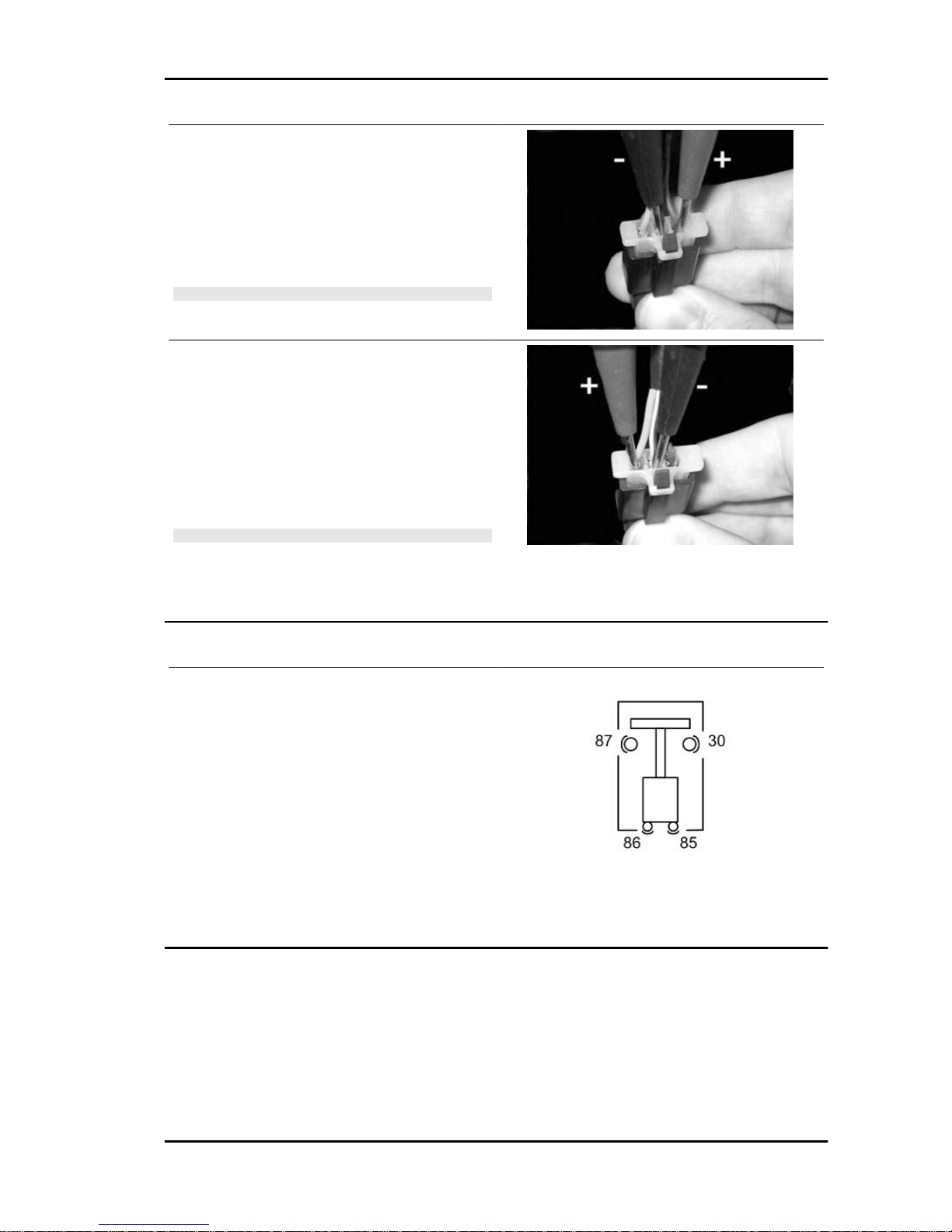
Check the supply voltage.
Keeping the connector in the position shown in the
photo, check for battery voltage (12 V) with the
polarity shown.
If incorrect values are measured, check the electrical system and the digital instrument.
N.B.
A DROP IN VOLTAGE OF 1 V IN RELATION TO THE BAT-
TERY VOLTAGE CAN BE CONSIDERED NORMAL.
Check the signal
Move the positive rod to the position shown in the
photo. Turn the front wheel very slowly and check
that the measured voltage is 0 V or battery voltage,
depending on the position taken up.
This condition should be repeated 16 times during
a complete revolution of the wheel.
N.B.
THE DIGITAL MULTIMETER IS NOT ABLE TO DISPLAY
THE VOLTAGE WHEN THE WHEEL IS ROTATED FAST.
If other voltages are measured or there is no alternation, replace the tone wheel.
Remote controls check
To check the operation of a remote control:
1) Check that, given regular conditions, there is no
continuity between terminals 87 and 30.
2) Apply a 12V voltage to power terminals 86 and
85 of the remote control.
3) With the remote control fed, check that there is
continuity between terminals 87 and 30.
4) If these conditions are not met, the remote control is surely damaged and, therefore, it should be
replaced.
Switches check
To check buttons and switches, check that, according to their position, the continuity of contacts is
correct as indicated in the following charts.
KEY
Ar: Orange Az: Sky Blue Bi: White Bl: Blue Gi: Yellow Gr: Grey Ma: Brown Ne: Black Ro: Pink Rs:
Red Ve: Green Vi: Purple
MSS Nexus 300 i.e. E3 ( 2008) Electrical system
ELE SYS - 83
Page 84
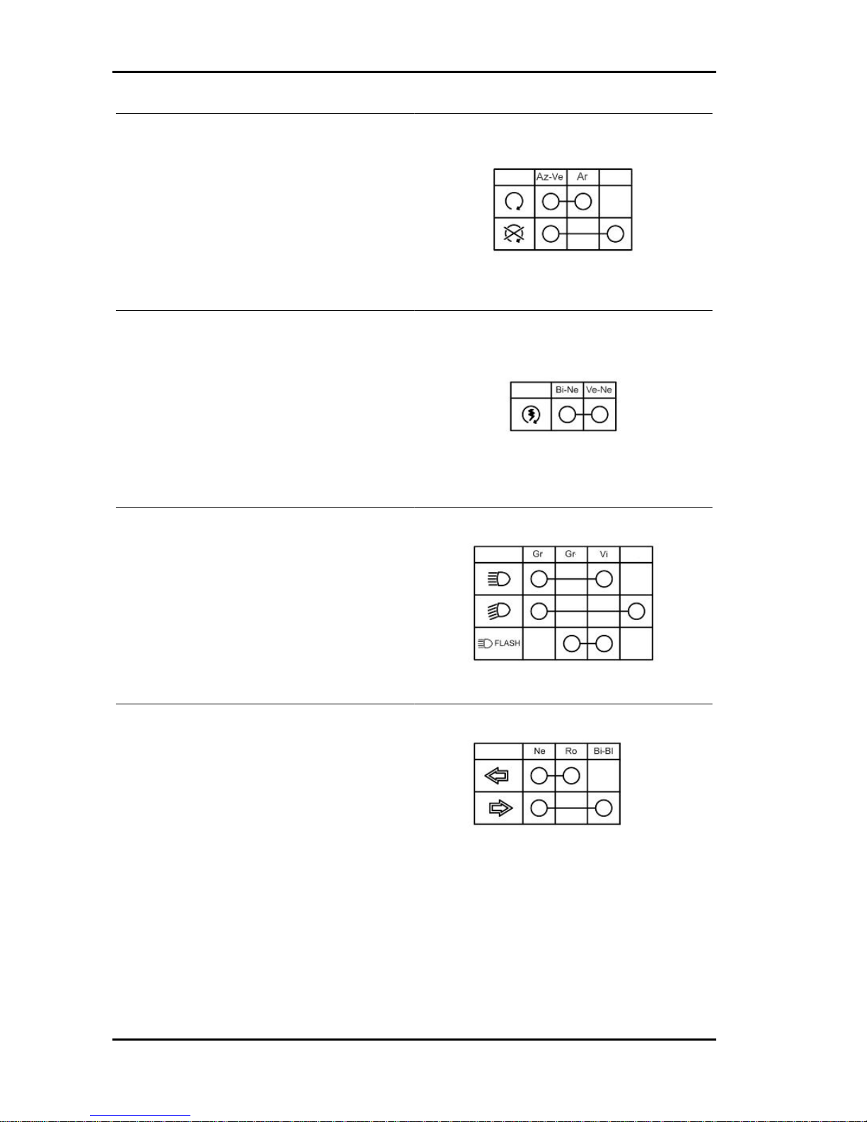
ENGINE STOP SWITCH
STARTER BUTTON
LIGHT SWITCH
TURN INDICATOR SWITCH
Electrical system MSS Nexus 300 i.e. E3 ( 2008)
ELE SYS - 84
Page 85
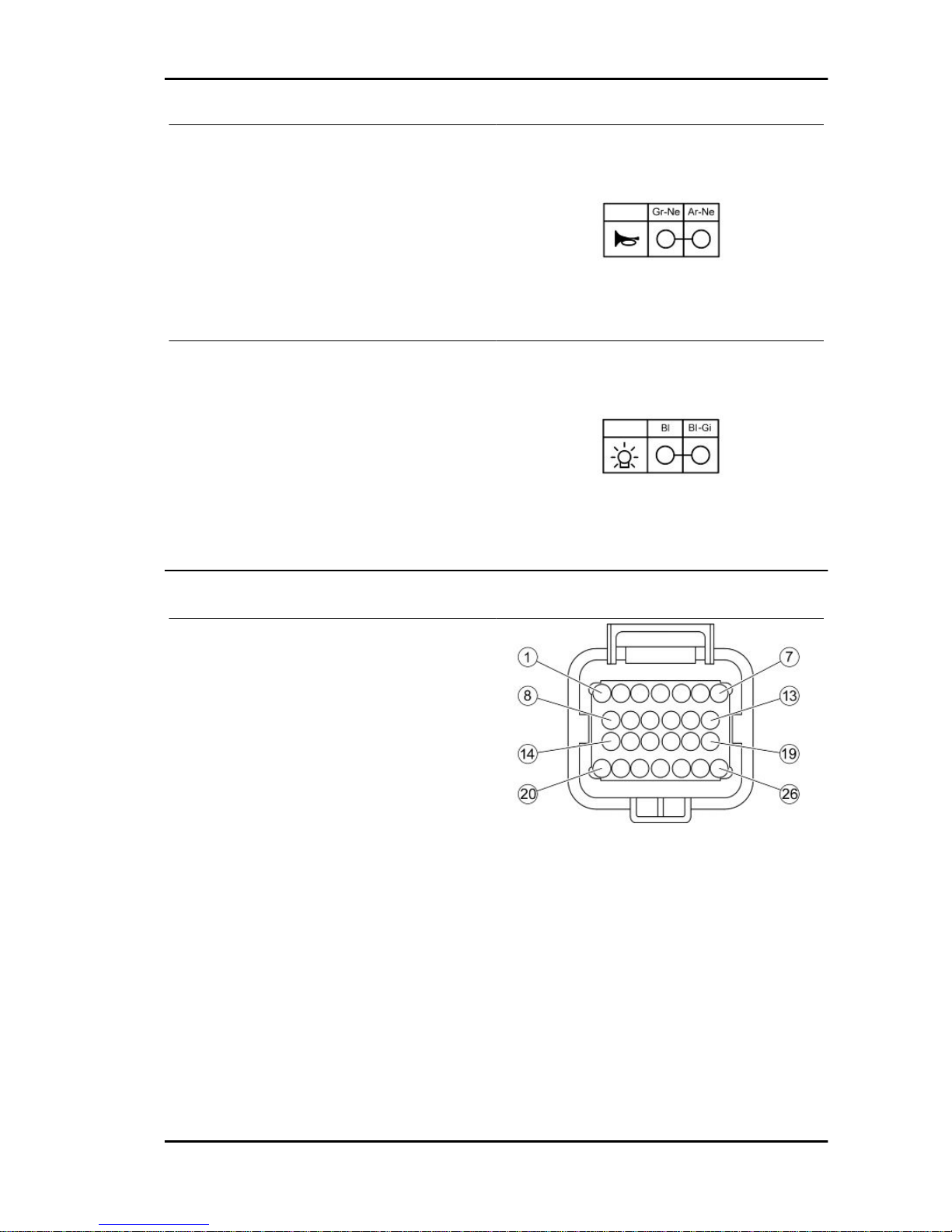
HORN BUTTON
HELMET COMPARTMENT LIGHT SWITCH
Connectors
INJECTION ELECTRONIC CONTROL UNIT
1. Injection telltale light (Brown-Black)
2. Rpm indicator (Green)
3. Not connected
4 Lambda probe negative terminal (Sky blue-
Black)
5 Live supply (White-Black)
6. Battery powered (White-Red)
7. Immobilizer aerial (Orange-White)
8. Electric fan remote control negative terminal
(Green-White)
9. Engine temperature (Yellow-Pink)
10. Not connected
11. Lambda probe positive (Sky blue-Yellow)
12. Engine stop switch (Orange)
13. Pick-up positive terminal (Red)
14. Injector negative terminal (Red-Yellow)
15. Pick-up negative terminal (White)
16. K line (Orange-Black)
MSS Nexus 300 i.e. E3 ( 2008) Electrical system
ELE SYS - 85
Page 86

17. Immobilizer warning light (Grey-Yellow)
18. Stand button (Brown-Red)
19. Not connected
20. Injection load remote control negative terminal
(Black-Purple)
21. Not connected
22. HV coil negative terminal (Pink-Black)
23. Not connected
24. Start-up enabling switch (Green-Blue)
25. Not connected
26. Ground (Black)
IMMOBILIZER AERIAL CONNECTOR
1. Live supply (White-Black)
2. Ground (Black)
3. Injection ECU (Orange-White)
ANTITHEFT DEVICE PRE-INSTALLATION
CONNECTOR
1. LHS Turn indicator bulbs (Pink)
2. RHS Turn indicator bulbs (White-Blue)
3. Ground (Black)
4. Battery powered (Red-Black)
5 Live supply (White-Black)
6. Helmet compartment light bulb (Blue-Yellow)
7. Not connected
8. Not connected
LAMBDA PROBE CONNECTOR
1. Positive from injection ECU (Sky blue-Yellow)
2. Negative from injection ECU (Sky blue-Black)
Electrical system MSS Nexus 300 i.e. E3 ( 2008)
ELE SYS - 86
Page 87
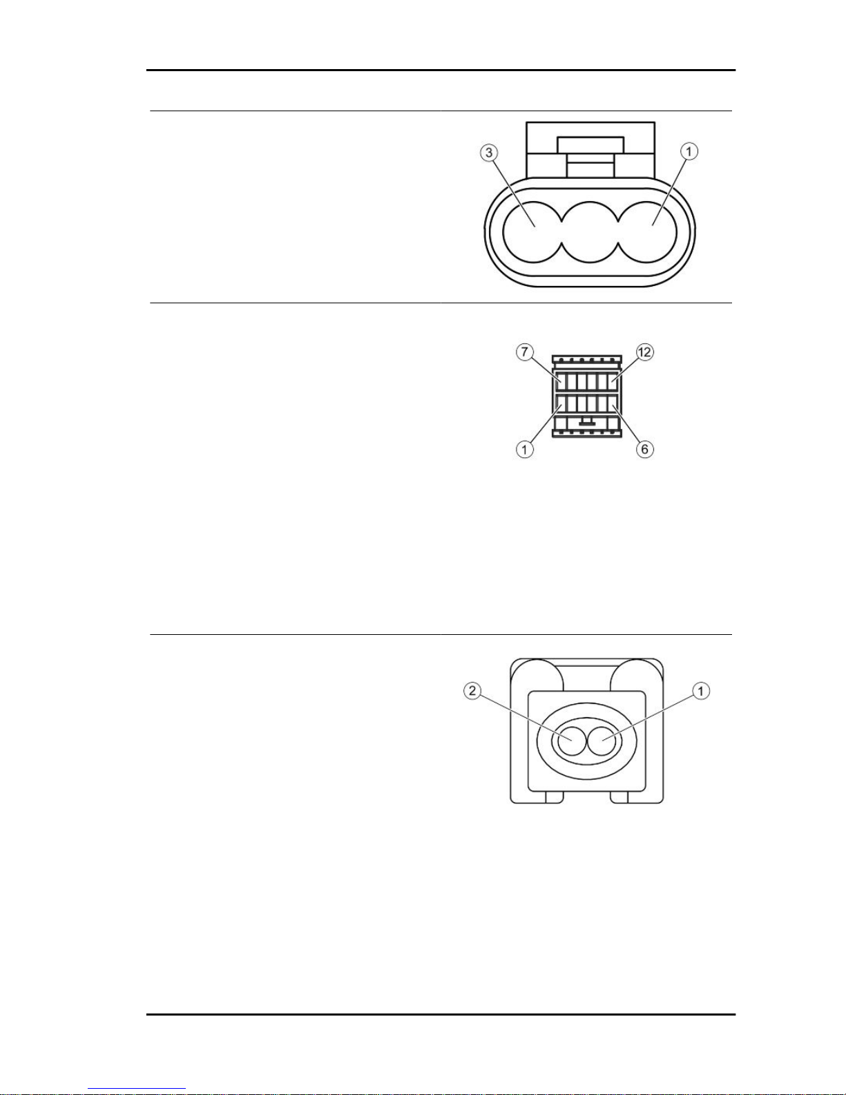
PICK-UP CONNECTOR
1. Positive from injection ECU (Red)
2. Negative from injection ECU (White)
3. Not connected
CONNECTOR FOR ELECTRICAL CONTROL
MANAGEMENT DEVICE
1. Live supply (White-Black)
2. Right turn indicator switch (White-Blue)
3. LHS turn indicator signal (Blue)
4. LHS turn indicator switch (Pink)
5. RHS turn indicator signal (Pink-Black)
6. MODE button remote (Sky blue-Red)
7. MODE button remote signal (Grey)
8. Oil pressure sensor (Pink-White)
9. Oil pressure sensor signal (White)
10. Not connected
11. Not connected
12. Not connected
FUEL INJECTOR CONNECTOR
1. Positive from remote control (Black-Green)
2. Negative from injection ECU (Red-Yellow)
MSS Nexus 300 i.e. E3 ( 2008) Electrical system
ELE SYS - 87
Page 88
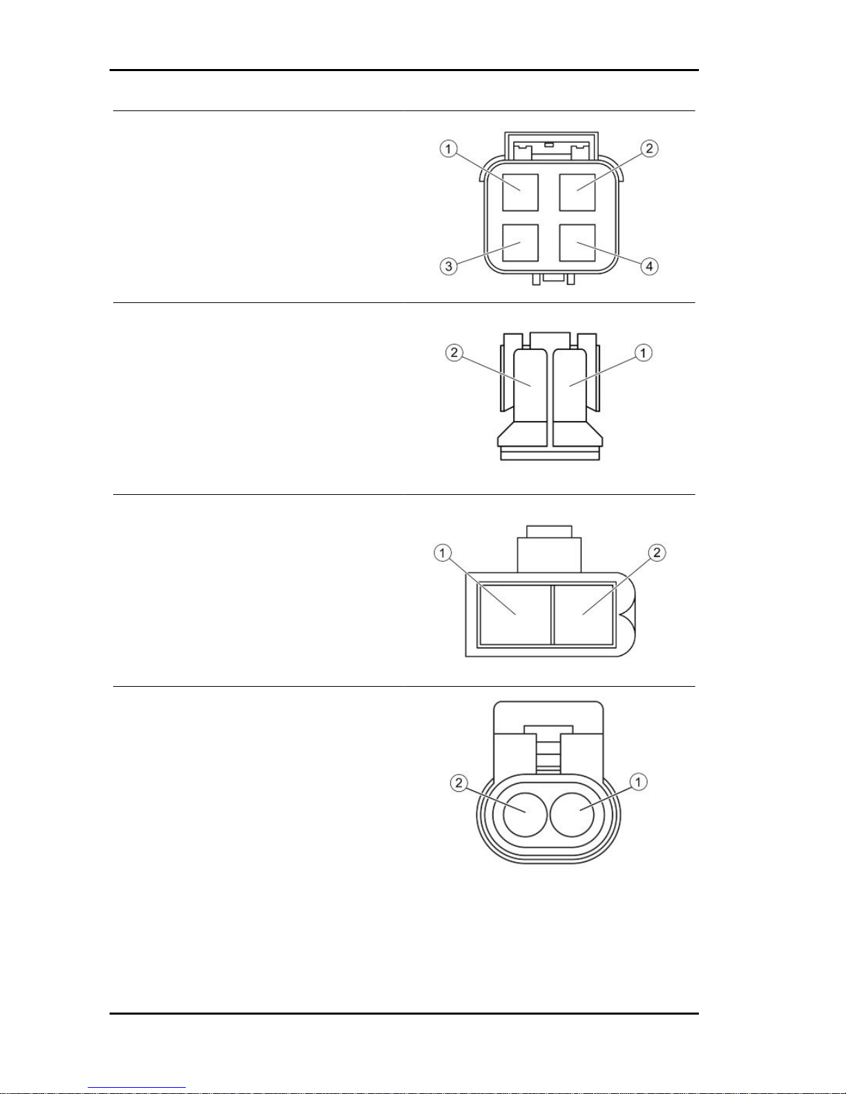
ENGINE TEMPERATURE SENSOR CONNECTOR
1. Injection ECU temperature signal (Yellow-Pink)
2. Indicator temperature signal (Orange)
3. Ground (Sky blue-Green)
4. Indicator temperature signal (Sky blue-Black)
ELECTRIC FAN CONNECTOR
1. Ground (Black)
2. Positive from remote control (Red-Black)
STAND BUTTON CONNECTOR
1. Ground (Sky blue-Green)
2. Injection ECU signal (Brown-Red)
HV COIL CONNECTOR
1. Positive from remote control (Black-Green)
2. Negative from injection ECU (Pink-Black)
Electrical system MSS Nexus 300 i.e. E3 ( 2008)
ELE SYS - 88
Page 89
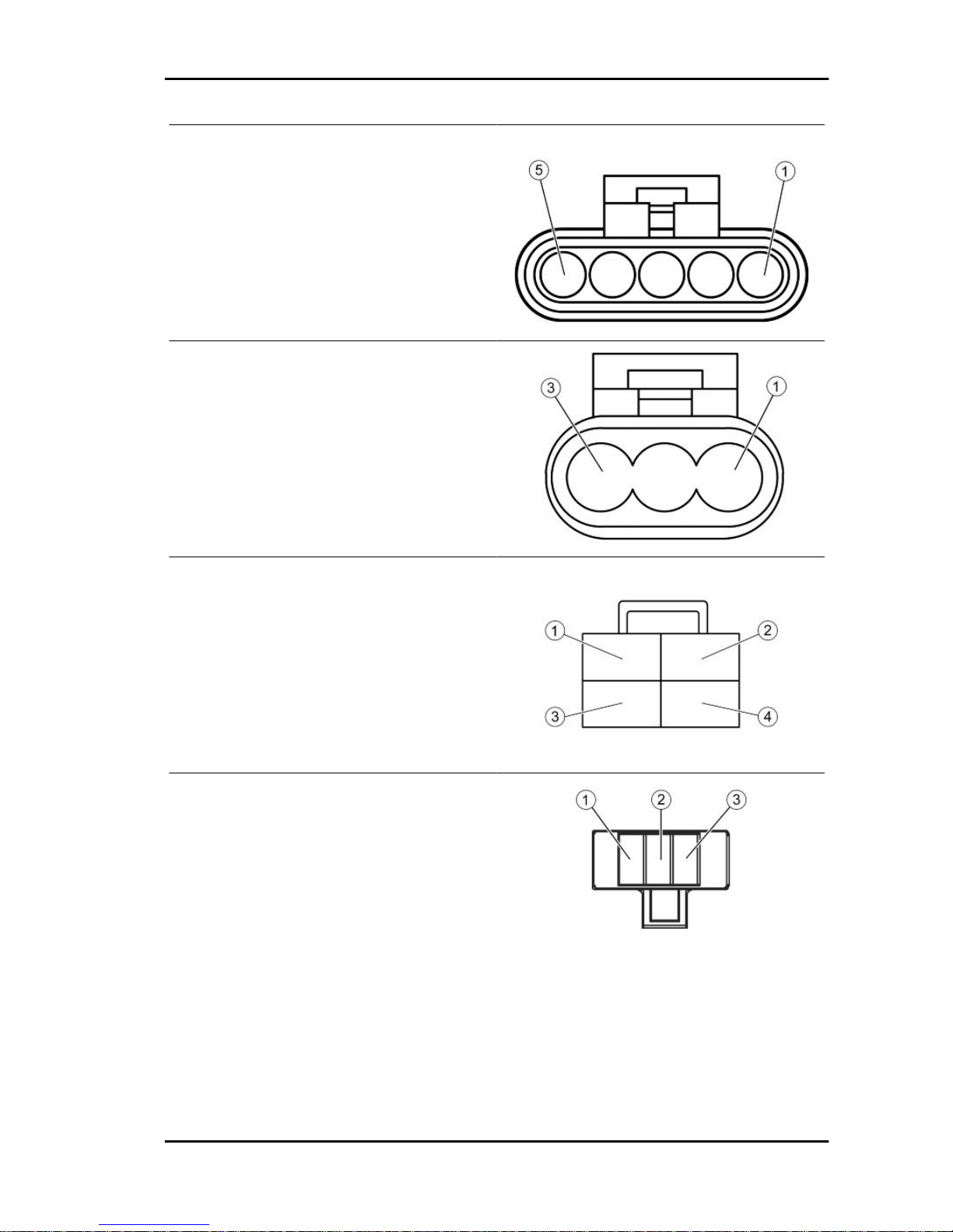
FUEL PUMP CONNECTOR AND FUEL LEVEL
TRANSMITTER
1. Not connected
2. Ground (Black)
3. Ground (Black)
4. Fuel level indicator (White-Green)
5. Positive from remote control (Black-Green)
DIAGNOSIS CONNECTOR
1. Not connected
2. Ground (Black)
3. K line (Orange-Black)
VOLTAGE REGULATOR CONNECTOR
1. Battery positive terminal (Red-White)
2. Ground (Black)
3. Battery positive terminal (Red-White)
4. Ground (Black)
WHEEL TURNING SENSOR CONNECTOR
1. Indicator signal (Sky blue)
2. Indicator signal (Grey-Black)
3. Indicator signal (Red)
MSS Nexus 300 i.e. E3 ( 2008) Electrical system
ELE SYS - 89
Page 90

INSTRUMENT PANEL CONNECTOR
1. Wheel turning sensor signal (Red)
2. Wheel turning sensor signal (Sky blue)
3. Wheel turning sensor signal (Grey-Black)
4. Instrument panel lighting (Yellow-Black)
5. Rpm indicator (Green)
6. Engine temperature signal (Orange)
7. Engine temperature signal (Sky blue-Black)
8. Oil pressure sensor signal (White)
9. RHS Turn indicator bulbs (White-Blue)
10. LHS Turn indicator bulbs (Pink)
11. Battery powered (Red-Black)
12. Immobilizer warning light (Grey-Yellow)
13. Live supply (White-Black)
14. MODE button remote signal (Grey)
15. Fuel level indicator (White-Green)
16. Ground (Black)
17. Injection telltale light (Brown-Black)
18. LHS turn indicator signal (Blue)
19. RHS turn indicator signal (Pink-Black)
20. Not connected
WARNING LIGHT UNIT CONNECTOR
1. Not connected
2. Not connected
3. High-beam warning light (Purple)
4. Ground (Black)
5. Headlight warning light (Yellow-Black)
6. Not connected
7. Not connected
8. Not connected
Electrical system MSS Nexus 300 i.e. E3 ( 2008)
ELE SYS - 90
Page 91

INDEX OF TOPICS
ENGINE FROM VEHICLE ENG VE
Page 92

Questa sezione descrive le operazioni da effettuare per lo smontaggio del motore dal veicolo.
Exhaust assy. Removal
- Remove the Lambda probe from its support and
disconnect it.
- Remove the retainer clamp.
- Undo the two exhaust manifold fixings on the
head. To unscrew the nuts that fix the muffler
flange to the head properly, use a jointed wrench
that allows, according to the travel direction, to get
also at the right nut. That is difficult to do with a
traditional straight wrench.
- Undo the three screws that fix the muffler to the
support arm.
- Remove the full muffler unit.
Remove the lambda probe from the manifold.
Engine from vehicle MSS Nexus 300 i.e. E3 ( 2008)
ENG VE - 92
Page 93

CAUTION: SHOULD IT BE NECESSARY TO REMOVE ONLY THE MUFFLER TIP, ALWAYS REPLACE THE GRAPHITE GASKET BETWEEN STUB AND TIP.
Removal of the engine from the vehicle
CAUTION
SUPPORT THE SCOOTER ADEQUATELY.
Disconnect the battery.
- Remove the side fairings.
- Remove the helmet compartment.
Remove the full muffler unit.
- Remove the air filter.
- Release the blow-by return pipe from the clamp
and disconnect it from the head.
CAUTION
THIS OPERATION MUST BE CARRIED OUT WHEN THE
ENGINE IS COLD.
- Remove the rear brake calliper and release the
rear brake piping from the four clamps of the engine.
- Get a + 2 l container in order to collect the coolant
and place it under the vehicle.
- Remove the pipe that feeds coolant into the pump
as shown in the photograph and then empty the
system.
- Remove the engine coolant outlet pipe as indicated.
MSS Nexus 300 i.e. E3 ( 2008) Engine from vehicle
ENG VE - 93
Page 94

- Disconnect:
- fuel piping and retainer clamp.
- injector connector.
- control unit connector.
- Remove the coolant outlet pipe from the motor
as indicated.
- Remove the spark plug cap.
- Remove the coolant temperature sensor con-
nector indicated in the photograph.
- Remove the throttle cables from the throttle body
by undoing the nuts indicated in the photograph.
- Remove the throttle cable retainer clamp on the
manifold.
Engine from vehicle MSS Nexus 300 i.e. E3 ( 2008)
ENG VE - 94
Page 95

- Remove the positive and negative wiring from the
starter motor as shown in the photograph.
- Disconnect the flywheel wiring connector.
- Remove the clamp indicated.
- Remove the cables from the retainer clamps on
the flywheel cover.
- Remove the lower screws of the right and left
shock absorber.
MSS Nexus 300 i.e. E3 ( 2008) Engine from vehicle
ENG VE - 95
Page 96
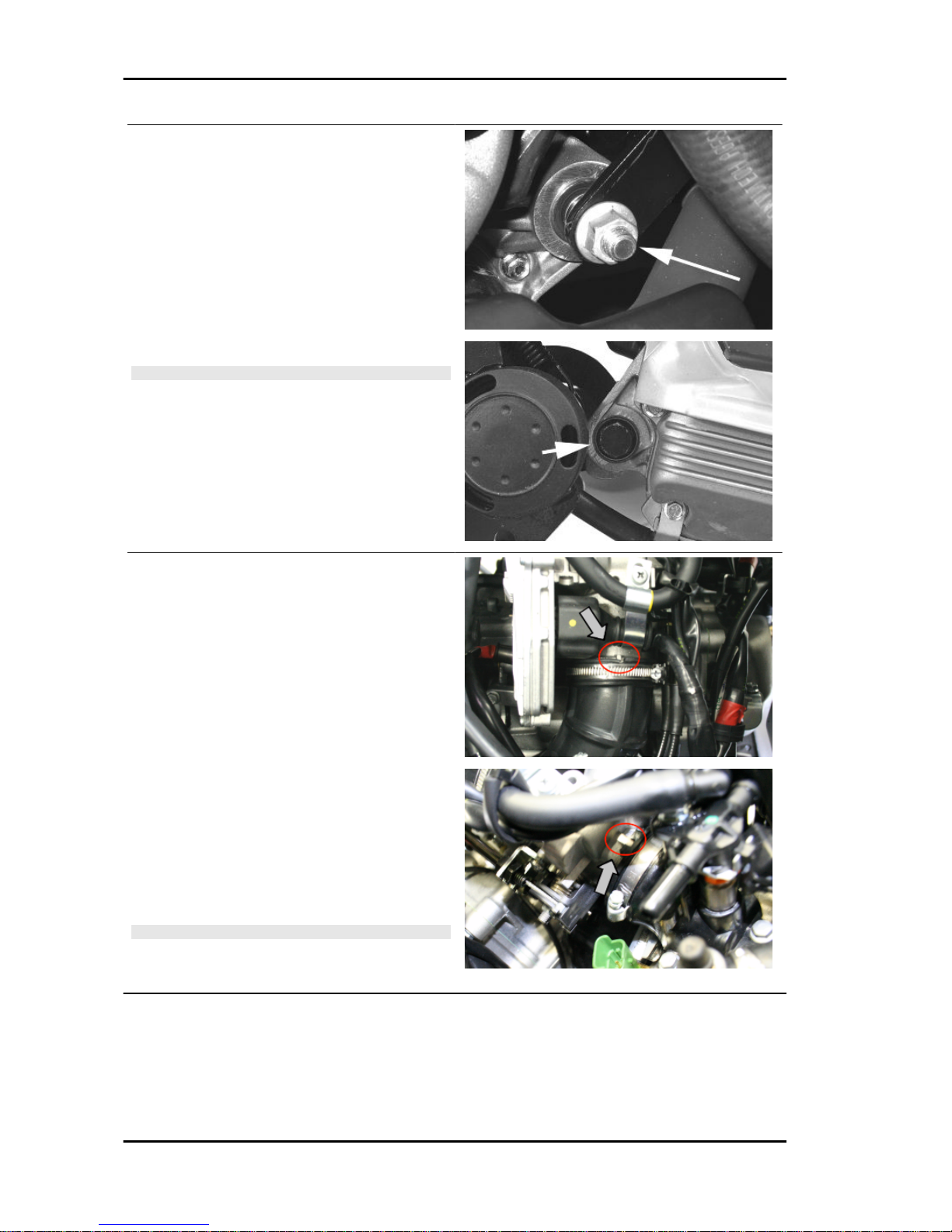
When refitting the engine onto the scooter, carry
out the removal operations but in reverse order
and respect the tightening torques shown in the
Specifications Chapter.
- Check the engine oil level and if necessary, top
it up with the recommended type.
- Fill and bleed the cooling circuit.
- Check accelerator and electric devices for correct
functioning.
CAUTION
PAY PARTICULAR ATTENTION TO POSITIONING THE
THROTTLE CONTROL TRANSMISSION PROPERLY.
Upon refitting the engine onto the scooter, carry
out the removal operations but in reverse order
and respect the tightening torques shown in the
«Specifications» Chapter.
- Check that there is a small clearance when the
valve is in abutment against the set screw.
-Check the engine oil level and if necessary, top it
up with the recommended type.
- Fill and bleed the cooling circuit.
- Check accelerator and electrical devices func-
tioning.
- Pay particular attention to the sleeve, be careful
to position the throttle body reference marks as indicated in the photograph.
CAUTION
PAY PARTICULAR ATTENTION TO POSITIONING THE
THROTTLE CONTROL TRANSMISSION PROPERLY.
Engine from vehicle MSS Nexus 300 i.e. E3 ( 2008)
ENG VE - 96
Page 97

INDEX OF TOPICS
ENGINE ENG
Page 98
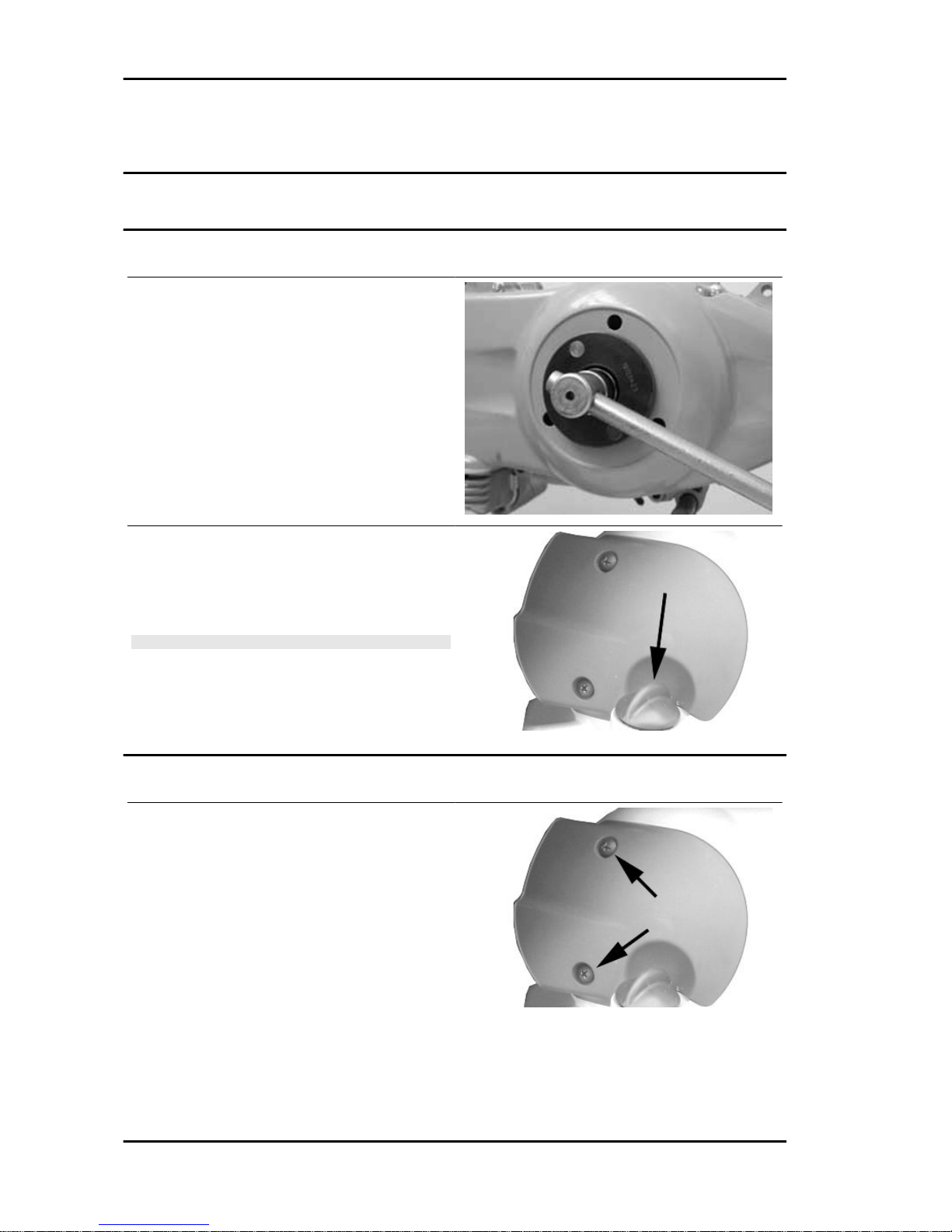
This section describes the operations to be carried out on the engine and the tools to be used.
Automatic transmission
Transmission cover
- To remove the transmission cover it is necessary
to remove the plastic cover first, by inserting a
screwdriver in the slotted holes. Using the clutch
bell lock wrench shown in the figure, remove the
driven pulley shaft locking nut and washer.
Specific tooling
020423Y driven pulley lock wrench
- Remove the cap/dipstick from the engine oil filling
hole.
- Remove the ten screws.
- Remove the transmission cover.
N.B.
WHEN YOU ARE REMOVING THE TRANSMISSION COVER
YOU MUST BE CAREFUL NOT TO DROP THE CLUTCH
BELL.
Air duct
- Remove the transmission compartment air intake
cover shown in the photograph.
Engine MSS Nexus 300 i.e. E3 ( 2008)
ENG - 98
Page 99
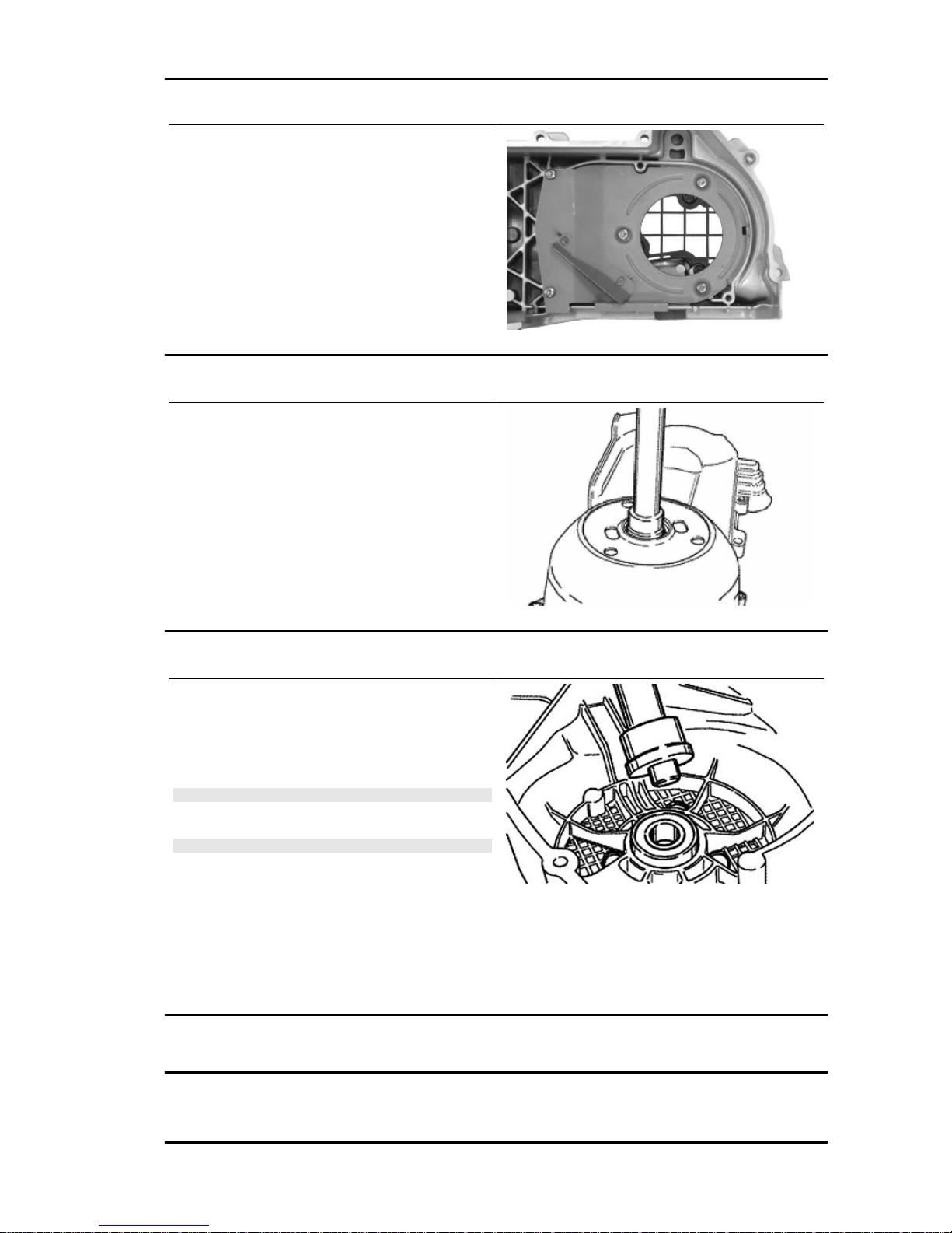
- Remove the five screws on two different levels
as well as the small casing.
Removing the driven pulley shaft bearing
- Remove the clip from the inside of the cover.
- Remove the bearing from the crankcase by
means of:
Specific tooling
020376Y Adaptor handle
020375Y Adaptor 28 x 30 mm
020412Y 15 mm guide
Refitting the driven pulley shaft bearing
- Slightly heat the crankcase from the inside so as
not to damage the painted surface.
- Insert the bearing in its seat.
- Refit the seeger ring.
CAUTION
USE AN APPROPRIATE REST SURFACE TO AVOID DAM-
AGING THE COVER PAINT.
N.B.
ALWAYS REPLACE THE BEARING WITH A NEW ONE
UPON REFITTING.
Specific tooling
020376Y Adaptor handle
020357Y 32 x 35 mm adaptor
020412Y 15 mm guide
Baffle roller
MSS Nexus 300 i.e. E3 ( 2008) Engine
ENG - 99
Page 100
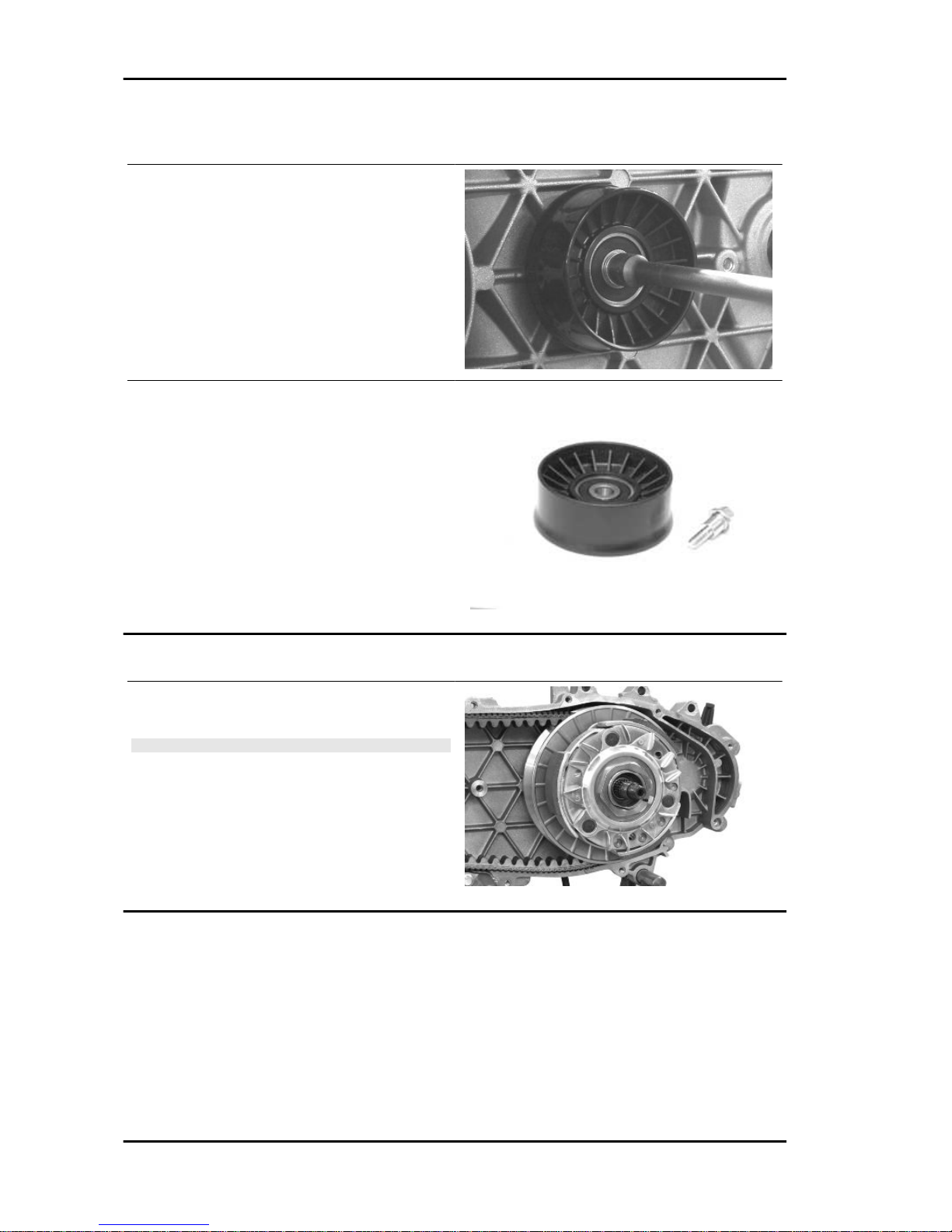
Plastic roller
- Check that the roller does not show signs of wear
and that it turns freely.
- Remove the special clamping screws as indica-
ted in the photograph
- Check the outside diameter of the roller does not
have defects that could jeopardise belt functioning
- For refitting, place the roller with the belt contain-
ment edge on the engine crankcase side
- Tighten the wrench to the prescribed torque.
Locking torques (N*m)
Anti-flapping roller 12 - 16
Removing the driven pulley
- Remove the clutch bell housing and the driven
pulley assembly.
N.B.
THE UNIT CAN ALSO BE REMOVED WITH THE DRIVING
PULLEY MOUNTED.
Engine MSS Nexus 300 i.e. E3 ( 2008)
ENG - 100
 Loading...