


When you installing AGP card, please make sure the following notice is fullyunderstood and practiced. If your AGP card has "AGP 4X notch"(show below), please make sure your AGP card is AGP 4X (1.5V).
Do not use AGP 2X card (3.3V) in this motherboard. It will
burn and damage the motherboard due to Intel® 845 chipset can't support AGP 2X(3.3V)..
Example 1: Diamond Vipper V770 golden finger is compatible with 2X/ 4X mode AGP slot. It can be switched between AGP 2X(3.3V) or 4X(1. 5V) mode by adjusting the jumper. The factory default for this card is 2X (3.3V). If you install this card in GA-8IRM series (or any AGP 4X only) motherboards without switching the jumper to 4X mode (1.5V), it will burn the motherboard.
Example 2: ATi Rage 128 Pro (Power Color)& SiS 305 golden finger is compatible with 2X/4X mode AGP slot, but it supports 2X(3.3V) only. If you install this card in GA-8IRM series (or any AGP 4X only) motherboards, it will burn the motherboard.
Note : Although Gigabyte's AG32S graphics card is based on ATi Rage 128 Pro chip, the design of AG32S is compliance with AGP 4X (1.5V) specification. Therefore, AG32S will work fine with Intel 845 / 850 based motherboards.
?Theauthor assumes no responsibility for anyerrors or omissions that may appear in this documentnor doesthe author make acommitment to up
date the informationcontainedherein.
?Third-party brands and namesare the propertyof their respective owners.
?Please donot removeany labelson motherboard, this mayvoid the warranty of this motherboard.
?Dueto rapid changein technology, some ofthe specifications mightbe out of date beforepublication of this booklet.

?EN 55011
?EN 55013
?EN 55014
?EN 55015
?EN 55020
?EN 55022
?DIN VDE 0855
?part 10
?part 12
?CEmarking
?EN 60065
?EN 60335
Declaration of Conform ity
We,Manuf acturer/Import er (f ull address)
G.B.T. Technology Trä dingGMbH
AusschlagerWeg 41,1F, 20537 Hamburg, Germany
declare t hat t he product
( descript ion of t he apparat us, system, inst allat ion t o which it ref ers)
Mother Board
GA-8IRM/GA-8IRML is in conf ormit y wit h
(ref erence t o t he specif icat ion under which conf ormit yis declared) in accordance wit h 89/336 EEC-EMC Direct ive
Lim it s and m et hods of m easurem ent |
?EN 61000-3-2* |
Dist urbances in supply system s cause |
|
of radio dist urbance charact erist ics of |
?EN 60555-2 |
by household appliances and sim ilar |
|
indust rial,scient ific and m edical (ISM |
|
elect rical equipm ent “ Harm onics” |
|
high f requency equipm ent |
|
|
|
Lim it s and m et hods of m easurem ent |
?EN 61000-3-3* |
Dist urbances in supply system s cause |
|
of radio dist urbance charact erist ics of |
?EN 60555-3 |
by household appliances and sim ilar |
|
broadcast receivers and associat ed |
elect rical equipm ent “ Volt age f luctuat ions” |
||
|
|||
equipm ent |
|
|
Lim it s and m et hods of m easurem ent of radio dist urbance charact erist ics of household elect rical appliances,
port able t ools and sim ilar elect rical apparat us
Lim it s and m et hods of m easurem ent of radio dist urbance charact erist ics of f luorescent lam ps and lum inaries
Im m unit y f rom radio int erf erence of broadcast receivers and associat ed equipm ent
Lim it s and m et hods of m easurem ent of radio dist urbance charact erist ics of inf orm at ion t echnology equipm ent
Cabled dist ribut ion syst em s; Equipm ent f or receiving and/or distribution f rom sound and t elevision signals
?EN 50081-1
?EN 50082-1
?EN 55081-2
?EN 55082-2
?ENV 55104
?EN50091-2
Generic em ission st andard Part 1: Residual com m ercialand light indust ry
Genericim m unit y st andard Part 1: Residual com m ercialand light indust ry
Generic em ission st andard Part 2: Indust rialenvironm ent
Generic em ission st andard Part 2: Indust rialenvironm ent
lm m unit y requirement s f or household appliances t ools and sim ilar apparat us
EMC requirem ent s for unint errupt ible powersyst em s(UPS)
|
(EC conf orm it y m arking) |
|
T hemanufacturer also declaresthe conformity of above mentioned product |
|
|
withthe actual requiredsafety standards in accordance with LVD 73/23EEC |
|
|
Saf et yrequirem ent s f or m ains operat ed |
?EN 60950 |
|
elect ronic and relat ed apparat us f or |
|
|
household and sim ilar general use |
|
|
Saf et y of household and sim ilar |
?EN 50091-1 |
|
elect rical appliances |
|
|
|
Manufacturer/Importer |
|
|
Signat ure: |
|
(S ta mp ) |
Dat e : Nov. 10, 2001 |
Nam e: |
|
|
|
Ti mmy H u an g
Timm y Huang

DECLARATION OF CONFORMITY
Pe r FCC Part 2 Sect ion 2.1077(a)
Responsibl e Party Name:G.B.T. INC. (U.S .A.)
Address: 17358 Railroad S treet
City of Industr y, CA 91748
Phone/Fax No:(818) 854-9338/ (818) 854-9339
h ereby declares th at th e produ ct
Pr oduct Name: Mother boar d
Model Number :GA-8IRM/GA-8IRML
Con forms to th e follo win g specification s:
FCC Part 15, Su b part B, Sectio n 15.107(a) an d Se ction 15.109 (a),Class B Dig i tal De v ice
Supplementar y Infor mation:
Th is dev ice co mplies wi th part 15 of th e FCC Ru les . Operati on is su bject to t h e follo win g two con diti on s: (1) Th is de v ice may n ot cau se h armfu l and (2)th is dev ice mu st accept an y in feren ce receiv ed, in clu din g th at may cau se u n desired operation .
Represen tativ e Person ’s Name: ERIC LU
Sig n atu re: Eric Lu
Dat e: No v . 10,2001
GA-8IRM Series
P4 Titan-DDR Motherboard
USER’S MANUAL
Pentium® 4 Processor Motherboard
Rev . 2.2 First Edition
12ME-8IRM -2201

GA-8IRM Series Motherboard |
|
Table of Content |
|
Revision History .............................................................................. |
4 |
Item Checklist .................................................................................. |
4 |
WARNING! ....................................................................................... |
5 |
Chapter 1 Introduction ....................................................................... |
6 |
Features Summary................................................................................................ |
6 |
GA-8IRM Series Motherboard Layout ............................................................... |
8 |
Chapter 2 Hardware Installation Process ............................................ |
9 |
Step 1: Install the Central Processing Unit (CPU) ......................................... |
10 |
CPU Installation ......................................................................................... |
10 |
CPU Heat Sink Installation ............................................................................ |
11 |
Step 2: Install memory modules ....................................................................... |
12 |
Step 3: Install expansion cards ......................................................................... |
13 |
Step 4: Connect ribbon cables, cabinet wires, and power supply ............. |
14 |
I/O Back Panel Introduction .......................................................................... |
14 |
Connectors Introduction ............................................................................... |
16 |
Chapter 3 BIOS Setup .................................................................... |
22 |
The Main Menu (For example: BIOS Ver. :F3b) ........................................... |
23 |
Standard CMOS Features ................................................................................. |
25 |
Advanced BIOS Features ................................................................................... |
28 |
Advanced Chipset Features .............................................................................. |
31 |
Integrated Peripherals ....................................................................................... |
34 |
2

|
Table of Content |
Power Management Setup ................................................................................ |
42 |
PnP/PCI Configurations ...................................................................................... |
46 |
PC Health Status .................................................................................................. |
48 |
Frequency/Voltage Control ................................................................................ |
50 |
Load Fail-Safe Defaults ...................................................................................... |
52 |
Load Optimized Defaults .................................................................................... |
53 |
Set Supervisor/User Password .......................................................................... |
54 |
Save & Exit Setup ................................................................................................. |
55 |
Exit Without Saving ............................................................................................. |
56 |
Chapter 4 Technical Reference ........................................................ |
57 |
Performance List ................................................................................................. |
57 |
Block Diagram ..................................................................................................... |
58 |
@ BIOS Introduction ........................................................................................... |
59 |
Easy TuneIIITM Introduction ................................................................................ |
60 |
Chapter 5 Appendix ....................................................................... |
61 |
3

GA-8IRM Series Motherboard
Revision History
Rev ision |
Rev ision Note |
Date |
|
|
|
2.2 |
Initial release of the GA-8IRM Series motherboard user's manual. |
Feb. 2002 |
|
|
|
Item Checklist
?The GA-8IRM Series motherboard
?IDE cable x 1/ Floppy cable x 1
?CD for motherboard driv er & utility (IUCD)
?I/O Shield
?GA-8IRM Series user’s manual
?USB Cable x 1
4

WARNING!
WARNING!
Computer motherboards and ex pansion cards contain v ery delicate Integrated Circuit (IC) chips. To protect them against damage from static electricity , y ou should follow some precautions whenev er y ou work on y our computer.
1.Unplug y our computer when working on the inside.
2.Use a grounded wrist strap before handling computer components. If y ou do not hav e
one, touch both of y our hands to a safely grounded object or to a metal object, such as the power supply case.
3.Hold components by the edges and try not touch the IC chips, leads or connectors, or other components.
4.Place components on a grounded antistatic pad or on the bag that came with the components whenev er the components are separated from the sy stem.
5.Ensure that the ATX power supply is switched off before y ou plug in or remov e the ATX power connector on the motherboard.
Installing the motherboard to the chassis…
If themotherboard has mounting holes, but they don’t line up with the holes on the base and there are no slots to attach the spacers, do not become alarmed y ou can still attach the spacers to the mounting holes. Just cut the bottom portion of the spacers (the spacer may be a little hard to cut off, so be careful of y our hands). In this way y ou can still attach the motherboard to the base without worry ing about short circuits. Sometimes y ou may need to use the plastic springs to isolate the screw from the motherboard PCB surface, because the circuit wire may be near by the hole. Be careful, don’t let the screw contact any printed circuit write or parts on the PCB that are near the fix ing hole, otherwise it may damage the board or cause board malfunctioning.
5

GA-8IRM Series Motherboard
Chapter 1 Introduction
Features Summary
Form Factor |
? 20.7cm x 24.3cm Micro ATX size form factor, 4 lay ers PCB. |
||
Motherboard |
? GA-8IRM Series Motherboard: |
||
|
GA-8IRM |
and GA-8IRML |
|
|
|
|
|
CPU |
? Socket 478 |
for Intel® Micro FC-PGA2 Pentium® 4 processor |
|
|
??Support Intel ® |
Pentium ® 4 (Northwood, 0.13um) processor |
|
|
? Intel Pentium® |
4 400MHz FSB |
|
|
? 2nd cache depend on CPU |
||
|
|
||
Chipset |
? Chipset 82845 HOST/AGP/Controller |
||
|
? 82801BA(ICH2) I/O Controller Hub |
||
|
|
||
Memory |
? 2 184-pin DDR DIMM sockets |
||
|
? Supports PC1600 DDR or PC2100 DDR SDRAM |
||
|
? Supports up to 2GB DRAM (Max ) |
||
|
? Supports only 2.5V DDR SDRAM |
||
|
? Supports 64bit ECC ty pe DRAM integrity mode |
||
|
|
|
|
I/O Control |
? W83627HF |
|
|
Slots |
? 1 AGP slot 4X (1.5V) dev ice support |
||
|
? 3 PCI slot supports 33MHz & PCI 2.2 compliant |
||
|
|
||
On-Board IDE |
? An IDE controller on the Intel 82801BA PCI chipset |
||
|
prov ides IDE HDD/CD-ROM with PIO, Bus Master (Ultra |
||
|
DMA33/ATA66/ATA100) operation modes. |
||
|
? Can connect up to four IDE dev ices |
||
|
|
||
On-Board Peripherals |
? 1 Floppy port supports 2 FDD with 360K, 720K,1.2M, 1.44M |
||
|
and 2.88M by tes. |
||
|
|
||
Hardware Monitor |
? CPU/Power/Sy stem Fan Rev olution detect |
||
|
? CPU/Power/Sy stem Fan Control |
||
|
? CPU Ov erheat Warning |
||
? 1 Parallel port supports Normal/EPP/ECP mode ? 2 Serial ports (COMA&COMB)
? 4 USB ports (Rear USB x 2, Front USB x 2) ? 1 IrDA connector for IR
to be continued......
6
Introduction
|
? Sy stem Voltage Detect |
On-Board Sound |
? AC97 CODEC (RealTek ALC201A) |
|
? Line In/Line Out/AUXIn/CD In/TEL/Mic In/CD In/Game Port |
|
|
On-Board LAN |
? Build in 82562ET Chipset * |
|
|
PS/2 Connector |
? PS/2 Key board interface and PS/2 Mouse interace |
|
|
BIOS |
? Licensed AWARD BIOS, 2M bit FWH |
|
|
Additional Features |
? Internal / Ex ternal Modem wake up |
|
? PS/2 Key board password power on |
|
? PS/2 Mouse power on |
|
? Wake on LAN |
|
? AC Recov ery |
|
? USB KB/Mouse wake up from S3 |
|
? Poly fuse for key board,USB,game port ov er-current protection |
|
? Supports @BIOS |
|
? Supports Easy TuneIII |
|
|
 Please set the CPU host frequency in accordance with y our processor’s specifications.
  We don’t recommend y ou to set the sy stem bus frequency ov er the CPU’s specification because these specific bus frequencies are not the standard specifications for CPU, chipset and most of the peripherals. Whether y our sy stem can run under these specific bus frequencies properly will depend on y our hardware configurations, including CPU, Chipsets,SDRAM,Cards… .etc.
* For GA-8IRML Only.
7

GA-8IRM Series Motherboard
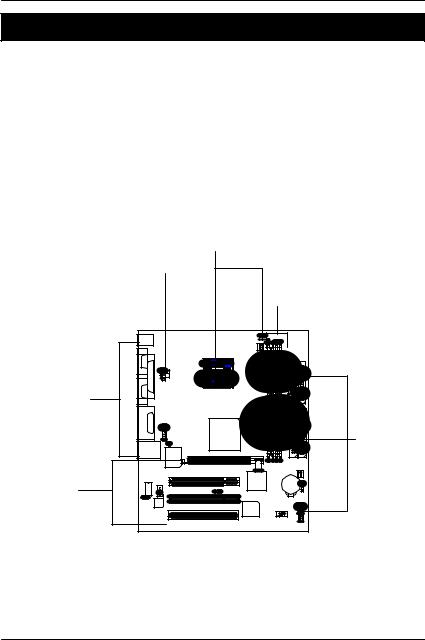
GA-8IRM Series Motherboard Layout
|
|
|
|
|
CPU_FAN |
|
|
|
|
|
KB_MS |
|
|
|
|
|
|
|
|
||
|
|
|
|
|
|
PWR_FAN |
|
|
|
FDD |
|
COMA |
|
|
|
|
|
|
|
ATX |
|
|
|
LPT |
|
AUX_12V |
|
|
|
|
|
|
|
|
|
|
|
|
|
|
|
|
|
|
COMB |
|
|
|
SOCKET478 |
|
|
|
|
|
|
|
|
|
|
|
|
|
|
|
|
|
|
|
|
|
GA-8IRM(L) |
|
|
|
|
|
MIC IN LINE OUT |
LINE IN |
GAME |
F AUDIO |
|
Brookdale |
|
|
|
|
|
|
|
|
|
|
|
|
|
|
|
|
|
|
|
|
CI |
|
|
|
|
|
|
|
U S B / |
LAN* |
|
W83627HF |
AGP |
|
|
|
|
|
|
|
|
|
DDR1 |
DDR2 |
IDE2 |
IDE1 FAN |
|||
|
|
|
IN |
|
PCI1 |
ICH2 |
|
|
|
SYS |
|
|
82562ET* |
CD |
|
|
|
|
|
||
|
|
|
|
|
|
|
BATTERY |
|
||
|
|
|
WOL |
|
|
|
|
IR |
||
|
|
|
|
|
|
|
|
|||
|
|
|
|
|
PCI2 |
|
|
|
|
|
LAN_EN* |
|
|
|
|
|
|
|
|||
AC97 |
|
|
|
|
|
|
F PANEL |
|||
|
|
|
|
|
FWH |
|
F_USB |
|||
|
|
|
|
|
PCI3 |
|
|
|
|
|
|
|
|
|
|
|
|
|
|
|
|
* For GA-8IRML only.
8
Hardw are Installation Process
Chapter 2 Hardware Installation Process
To set up your computer, you must complete the following steps: Step 1- Install the Central Processing Unit (CPU)
Step 2- Install memory modules Step 3- Install expansion cards
Step 4- Connect ribbon cables, cabinet wires, and power supply Step 5- Setup BIOS software
Step 6- Install supporting software tools
Step1
Step4
Step 2
Step 4
Step 4
Step3
9
GA-8IRM Series Motherboard
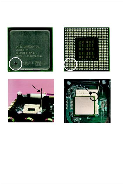
Step 1: Install the Central Processing Unit (CPU)
CPU Installation
Pin1 indicator |
Pin1 indicator |
CPU Top View |
CPU Bottom View |
Socket Actuation Lever |
Pin1 indicator |
|
1.Pull up the CPU socket lev er and up to 90-degree angle.
3.Press down the CPU socket lev er and finish CPU installation.
2.Locate Pin 1 in the socket and look for a (golden) cut edge on the CPU upper corner. Then insert the CPU into the socket.
?Please make sure the CPU type is supported by the motherboard.
?If you do not match the CPU socket Pin 1 and CPU cut edge well, it will cause improper installation. Please change the insert orientation.
10
Hardw are Installation Process
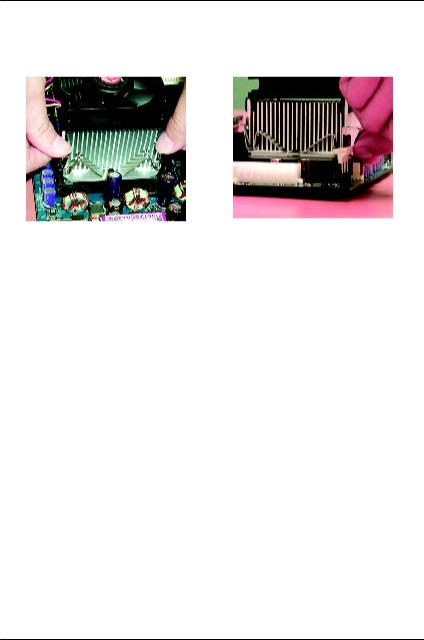
CPU Heat Sink Installation
1. Hook one end of the cooler |
2. Hook the other end of the |
bracket to the CPU socket first. |
cooler bracket to the CPU |
|
socket. |
?Please use Intel approved cooling fan.
?We recommend you to apply the thermal tape to provide better heat conduction between your CPU and heatsink.
(The CPU cooling fan might stick to the CPU due to the hardening of the thermal paste. During this condition if you try to remove the cooling fan, you might pull the processor out of the CPU socket alone with the cooling fan, and might damage the processor. To avoid this from happening, we suggest you to either use thermal tape instead of thermal paste, or remove the cooling fan with extreme caution.)
?Make sure the CPU fan power cable is plugged in to the CPU fan connector, this completes the installation.
?Please refer to CPU heat sink user’s manual for more detail installation procedure.
11
 Loading...