

Page 1

GE
Measurement & Control Gas Analysis
XMTC
User’s Manual
910-217 Rev. G
October 2013
Page 2

Page 3

XMTC
Thermal Conductivity Binary Gas Transmitter
User’s Manual
910-217 Rev. G
October 2013
www.ge-mcs.com
©2013 General Electric Company. All rights reserved.
Technical content subject to change without notice.
Page 4

[no content intended for this page]
ii
Page 5

Preface
Information Paragraphs
Note: These paragraphs provide information that provides a deeper understanding of the situation, but is not
essential to the proper completion of the instructions.
IMPORTANT: These paragraphs provide information that emphasizes instructions that are essential to proper setup of
the equipment. Failure to follow these instructions carefully may cause unreliable performance.
CAUTION! This symbol indicates a risk of potential minor personal injury and/or severe
damage to the equipment, unless these instructions are followed carefully.
WARNING! This symbol indicates a risk of potential serious personal injury, unless these
instructions are followed carefully.
Safety Issues
WARNING! It is the responsibility of the user to make sure all local, county, state and national
codes, regulations, rules and laws related to safety and safe operating conditions are met for
each installation.
Auxiliary Equipment
Local Safety Standards
The user must make sure that he operates all auxiliary equipment in accordance with local codes, standards,
regulations, or laws applicable to safety.
Working Area
WARNING! Auxiliary equipment may have both manual and automatic modes of operation. As
equipment can move suddenly and without warning, do not enter the work cell of this equipment
during automatic operation, and do not enter the work envelope of this equipment during
manual operation. If you do, serious injury can result..
WARNING! Make sure that power to the auxiliary equipment is turned OFF and locked out
before you perform maintenance procedures on the equipment.
XMTC User’s Manual iii
Page 6

Preface
Auxiliary Equipment (cont.)
Qualification of Personnel
Make sure that all personnel have manufacturer-approved training applicable to the auxiliary equipment.
Personal Safety Equipment
Make sure that operators and maintenance personnel have all safety equipment applicable to the auxiliary equipment.
Examples include safety glasses, protective headgear, safety shoes, etc.
Unauthorized Operation
Make sure that unauthorized personnel cannot gain access to the operation of the equipment.
Environmental Compliance
Waste Electrical and Electronic Equipment (WEEE) Directive
GE Measurement & Control Solutions is an active participant in Europe’s Waste Electrical and Electronic Equipment
(WEEE) take-back initiative, directive 2002/96/EC.
The equipment that you bought has required the extraction and use of natural resources for its production. It may
contain hazardous substances that could impact health and the environment.
In order to avoid the dissemination of those substances in our environment and to diminish the pressure on the natural
resources, we encourage you to use the appropriate take-back systems. Those systems will reuse or recycle most of the
materials of your end life equipment in a sound way.
The crossed-out wheeled bin symbol invites you to use those systems.
If you need more information on the collection, reuse and recycling systems, please contact your local or regional
waste administration.
Visit http://www.ge-mcs.com/en/about-us/environmental-health-and-safety/1741-weee-req.html
take-back instructions and more information about this initiative.
iv XMTC User’s Manual
for
Page 7

Contents
Chapter 1. Features and Capabilities
1.1 Introduction . . . . . . . . . . . . . . . . . . . . . . . . . . . . . . . . . . . . . . . . . . . . . . . . . . . . . . . . . . . . . . . . . . . . . . . . . . . . . . .1
1.2 Basic Features . . . . . . . . . . . . . . . . . . . . . . . . . . . . . . . . . . . . . . . . . . . . . . . . . . . . . . . . . . . . . . . . . . . . . . . . . . . . .1
1.3 Theory of Operation. . . . . . . . . . . . . . . . . . . . . . . . . . . . . . . . . . . . . . . . . . . . . . . . . . . . . . . . . . . . . . . . . . . . . . . . .2
1.4 System Description . . . . . . . . . . . . . . . . . . . . . . . . . . . . . . . . . . . . . . . . . . . . . . . . . . . . . . . . . . . . . . . . . . . . . . . . .3
1.4.1 Packaging and Temperature Rating . . . . . . . . . . . . . . . . . . . . . . . . . . . . . . . . . . . . . . . . . . . . . . . . . . . . . . . .3
1.4.2 2-Port (Sealed Reference Gas) Version. . . . . . . . . . . . . . . . . . . . . . . . . . . . . . . . . . . . . . . . . . . . . . . . . . . . . .4
1.4.3 4-Port (Flowing Reference Gas) Version . . . . . . . . . . . . . . . . . . . . . . . . . . . . . . . . . . . . . . . . . . . . . . . . . . . .5
1.4.4 Sample System . . . . . . . . . . . . . . . . . . . . . . . . . . . . . . . . . . . . . . . . . . . . . . . . . . . . . . . . . . . . . . . . . . . . . . . . 6
1.4.5 Extra Cable (optional). . . . . . . . . . . . . . . . . . . . . . . . . . . . . . . . . . . . . . . . . . . . . . . . . . . . . . . . . . . . . . . . . . .6
1.4.6 Power Supply (optional) . . . . . . . . . . . . . . . . . . . . . . . . . . . . . . . . . . . . . . . . . . . . . . . . . . . . . . . . . . . . . . . . . 6
1.4.7 TMO2D-TC Display (optional) . . . . . . . . . . . . . . . . . . . . . . . . . . . . . . . . . . . . . . . . . . . . . . . . . . . . . . . . . . .6
1.4.8 XDP Display (Optional) . . . . . . . . . . . . . . . . . . . . . . . . . . . . . . . . . . . . . . . . . . . . . . . . . . . . . . . . . . . . . . . . .6
1.5 Typical Applications . . . . . . . . . . . . . . . . . . . . . . . . . . . . . . . . . . . . . . . . . . . . . . . . . . . . . . . . . . . . . . . . . . . . . . . .7
Chapter 2. Installation
2.1 Introduction . . . . . . . . . . . . . . . . . . . . . . . . . . . . . . . . . . . . . . . . . . . . . . . . . . . . . . . . . . . . . . . . . . . . . . . . . . . . . . .9
2.2 Mounting the XMTC Transmitter . . . . . . . . . . . . . . . . . . . . . . . . . . . . . . . . . . . . . . . . . . . . . . . . . . . . . . . . . . . . . .9
2.3 Mounting the Sample System . . . . . . . . . . . . . . . . . . . . . . . . . . . . . . . . . . . . . . . . . . . . . . . . . . . . . . . . . . . . . . . .10
2.3.1 Manual, 2-Port (Sealed Reference Gas) Sample System . . . . . . . . . . . . . . . . . . . . . . . . . . . . . . . . . . . . . . .10
2.3.2 Manual, 4-Port (Flowing Reference Gas) Sample System. . . . . . . . . . . . . . . . . . . . . . . . . . . . . . . . . . . . . . 11
2.3.3 Sample Systems with Automatic Switching. . . . . . . . . . . . . . . . . . . . . . . . . . . . . . . . . . . . . . . . . . . . . . . . . 11
2.4 Wiring the XMTC Transmitter. . . . . . . . . . . . . . . . . . . . . . . . . . . . . . . . . . . . . . . . . . . . . . . . . . . . . . . . . . . . . . . .12
2.4.1 Grounding the Enclosure . . . . . . . . . . . . . . . . . . . . . . . . . . . . . . . . . . . . . . . . . . . . . . . . . . . . . . . . . . . . . . .12
2.4.2 CE Mark Compliance . . . . . . . . . . . . . . . . . . . . . . . . . . . . . . . . . . . . . . . . . . . . . . . . . . . . . . . . . . . . . . . . . .13
2.4.3 Cable Specifications . . . . . . . . . . . . . . . . . . . . . . . . . . . . . . . . . . . . . . . . . . . . . . . . . . . . . . . . . . . . . . . . . . .13
2.4.4 Wiring the Signal Connections . . . . . . . . . . . . . . . . . . . . . . . . . . . . . . . . . . . . . . . . . . . . . . . . . . . . . . . . . . . 14
2.5 Connecting to Other Components . . . . . . . . . . . . . . . . . . . . . . . . . . . . . . . . . . . . . . . . . . . . . . . . . . . . . . . . . . . . .17
2.5.1 PS5R-C24 Power Supply . . . . . . . . . . . . . . . . . . . . . . . . . . . . . . . . . . . . . . . . . . . . . . . . . . . . . . . . . . . . . . .17
2.5.2 TMO2D Display . . . . . . . . . . . . . . . . . . . . . . . . . . . . . . . . . . . . . . . . . . . . . . . . . . . . . . . . . . . . . . . . . . . . . .18
2.5.3 XDP Display. . . . . . . . . . . . . . . . . . . . . . . . . . . . . . . . . . . . . . . . . . . . . . . . . . . . . . . . . . . . . . . . . . . . . . . . .18
2.5.4 Moisture Series Analyzers . . . . . . . . . . . . . . . . . . . . . . . . . . . . . . . . . . . . . . . . . . . . . . . . . . . . . . . . . . . . . .18
XMTC User’s Manual v
Page 8

Contents
Chapter 3. Operation and Programming
3.1 Introduction . . . . . . . . . . . . . . . . . . . . . . . . . . . . . . . . . . . . . . . . . . . . . . . . . . . . . . . . . . . . . . . . . . . . . . . . . . . . . .19
3.2 Powering Up the XMTC. . . . . . . . . . . . . . . . . . . . . . . . . . . . . . . . . . . . . . . . . . . . . . . . . . . . . . . . . . . . . . . . . . . . .19
3.3 Starting the Sample Gas . . . . . . . . . . . . . . . . . . . . . . . . . . . . . . . . . . . . . . . . . . . . . . . . . . . . . . . . . . . . . . . . . . . . .19
3.4 Programming with IDM™ . . . . . . . . . . . . . . . . . . . . . . . . . . . . . . . . . . . . . . . . . . . . . . . . . . . . . . . . . . . . . . . . . . .20
3.5 The Edit Functions Menu. . . . . . . . . . . . . . . . . . . . . . . . . . . . . . . . . . . . . . . . . . . . . . . . . . . . . . . . . . . . . . . . . . . .20
3.6 Field Cal . . . . . . . . . . . . . . . . . . . . . . . . . . . . . . . . . . . . . . . . . . . . . . . . . . . . . . . . . . . . . . . . . . . . . . . . . . . . . . . . .21
3.6.1 Perform Cal . . . . . . . . . . . . . . . . . . . . . . . . . . . . . . . . . . . . . . . . . . . . . . . . . . . . . . . . . . . . . . . . . . . . . . . . . .21
3.6.2 Configure Cal . . . . . . . . . . . . . . . . . . . . . . . . . . . . . . . . . . . . . . . . . . . . . . . . . . . . . . . . . . . . . . . . . . . . . . . .23
3.6.3 Calibration Drifts. . . . . . . . . . . . . . . . . . . . . . . . . . . . . . . . . . . . . . . . . . . . . . . . . . . . . . . . . . . . . . . . . . . . . .26
3.6.4 Clear Calibration . . . . . . . . . . . . . . . . . . . . . . . . . . . . . . . . . . . . . . . . . . . . . . . . . . . . . . . . . . . . . . . . . . . . . .27
3.6.5 Hold Last Value. . . . . . . . . . . . . . . . . . . . . . . . . . . . . . . . . . . . . . . . . . . . . . . . . . . . . . . . . . . . . . . . . . . . . . .27
3.7 4-20 mA Output . . . . . . . . . . . . . . . . . . . . . . . . . . . . . . . . . . . . . . . . . . . . . . . . . . . . . . . . . . . . . . . . . . . . . . . . . . .28
3.7.1 4-20 mA Range . . . . . . . . . . . . . . . . . . . . . . . . . . . . . . . . . . . . . . . . . . . . . . . . . . . . . . . . . . . . . . . . . . . . . . .28
3.7.2 4 and 20 mA Cal . . . . . . . . . . . . . . . . . . . . . . . . . . . . . . . . . . . . . . . . . . . . . . . . . . . . . . . . . . . . . . . . . . . . . .29
3.7.3 4-20 mA % Test. . . . . . . . . . . . . . . . . . . . . . . . . . . . . . . . . . . . . . . . . . . . . . . . . . . . . . . . . . . . . . . . . . . . . . .30
3.7.4 % Gas Test. . . . . . . . . . . . . . . . . . . . . . . . . . . . . . . . . . . . . . . . . . . . . . . . . . . . . . . . . . . . . . . . . . . . . . . . . . .31
3.8 Error Handler . . . . . . . . . . . . . . . . . . . . . . . . . . . . . . . . . . . . . . . . . . . . . . . . . . . . . . . . . . . . . . . . . . . . . . . . . . . . .31
3.8.1 Total Drift Error. . . . . . . . . . . . . . . . . . . . . . . . . . . . . . . . . . . . . . . . . . . . . . . . . . . . . . . . . . . . . . . . . . . . . . .32
3.8.2 Drift/Cal Error . . . . . . . . . . . . . . . . . . . . . . . . . . . . . . . . . . . . . . . . . . . . . . . . . . . . . . . . . . . . . . . . . . . . . . . .33
3.8.3 Gas mV Under/Over Range. . . . . . . . . . . . . . . . . . . . . . . . . . . . . . . . . . . . . . . . . . . . . . . . . . . . . . . . . . . . . .34
3.8.4 Gas % Under/Over Range . . . . . . . . . . . . . . . . . . . . . . . . . . . . . . . . . . . . . . . . . . . . . . . . . . . . . . . . . . . . . . .34
3.9 Factory Cal . . . . . . . . . . . . . . . . . . . . . . . . . . . . . . . . . . . . . . . . . . . . . . . . . . . . . . . . . . . . . . . . . . . . . . . . . . . . . . .35
3.9.1 Edit # of Points . . . . . . . . . . . . . . . . . . . . . . . . . . . . . . . . . . . . . . . . . . . . . . . . . . . . . . . . . . . . . . . . . . . . . . .35
3.9.2 Edit Point X. . . . . . . . . . . . . . . . . . . . . . . . . . . . . . . . . . . . . . . . . . . . . . . . . . . . . . . . . . . . . . . . . . . . . . . . . .36
3.10 The Advanced Option. . . . . . . . . . . . . . . . . . . . . . . . . . . . . . . . . . . . . . . . . . . . . . . . . . . . . . . . . . . . . . . . . . . . . . .37
3.10.1 Fast Response . . . . . . . . . . . . . . . . . . . . . . . . . . . . . . . . . . . . . . . . . . . . . . . . . . . . . . . . . . . . . . . . . . . . . . .38
3.10.2 Language . . . . . . . . . . . . . . . . . . . . . . . . . . . . . . . . . . . . . . . . . . . . . . . . . . . . . . . . . . . . . . . . . . . . . . . . . . .38
3.10.3 Meter ID . . . . . . . . . . . . . . . . . . . . . . . . . . . . . . . . . . . . . . . . . . . . . . . . . . . . . . . . . . . . . . . . . . . . . . . . . . .40
Chapter 4. Calibration
4.1 Introduction . . . . . . . . . . . . . . . . . . . . . . . . . . . . . . . . . . . . . . . . . . . . . . . . . . . . . . . . . . . . . . . . . . . . . . . . . . . . . .43
4.2 Gas Ranges and Types . . . . . . . . . . . . . . . . . . . . . . . . . . . . . . . . . . . . . . . . . . . . . . . . . . . . . . . . . . . . . . . . . . . . . .43
4.3 Required Equipment and Materials . . . . . . . . . . . . . . . . . . . . . . . . . . . . . . . . . . . . . . . . . . . . . . . . . . . . . . . . . . . .44
4.4 Preparing the Transmitter for Calibration. . . . . . . . . . . . . . . . . . . . . . . . . . . . . . . . . . . . . . . . . . . . . . . . . . . . . . . .45
4.5 2-Port (Sealed Reference Gas) Calibration . . . . . . . . . . . . . . . . . . . . . . . . . . . . . . . . . . . . . . . . . . . . . . . . . . . . . .46
4.6 4-Port (Flowing Reference Gas) Calibration . . . . . . . . . . . . . . . . . . . . . . . . . . . . . . . . . . . . . . . . . . . . . . . . . . . . .47
Chapter 5. Specifications
5.1 Performance . . . . . . . . . . . . . . . . . . . . . . . . . . . . . . . . . . . . . . . . . . . . . . . . . . . . . . . . . . . . . . . . . . . . . . . . . . . . . .49
5.2 Functional. . . . . . . . . . . . . . . . . . . . . . . . . . . . . . . . . . . . . . . . . . . . . . . . . . . . . . . . . . . . . . . . . . . . . . . . . . . . . . . .50
5.3 Physical. . . . . . . . . . . . . . . . . . . . . . . . . . . . . . . . . . . . . . . . . . . . . . . . . . . . . . . . . . . . . . . . . . . . . . . . . . . . . . . . . .50
5.4 Accessories. . . . . . . . . . . . . . . . . . . . . . . . . . . . . . . . . . . . . . . . . . . . . . . . . . . . . . . . . . . . . . . . . . . . . . . . . . . . . . .51
vi XMTC User’s Manual
Page 9

Contents
Appendix A. Supplemental Information
A.1 Ordering Information. . . . . . . . . . . . . . . . . . . . . . . . . . . . . . . . . . . . . . . . . . . . . . . . . . . . . . . . . . . . . . . . . . . . . . .53
A.2 Calibration Specification Ordering Information . . . . . . . . . . . . . . . . . . . . . . . . . . . . . . . . . . . . . . . . . . . . . . . . . .54
A.3 XMTC PCB Subassemblies. . . . . . . . . . . . . . . . . . . . . . . . . . . . . . . . . . . . . . . . . . . . . . . . . . . . . . . . . . . . . . . . . .55
A.4 Sample Calibration Sheet. . . . . . . . . . . . . . . . . . . . . . . . . . . . . . . . . . . . . . . . . . . . . . . . . . . . . . . . . . . . . . . . . . . .56
A.5 Relative Thermal Conductivity of Common Gases. . . . . . . . . . . . . . . . . . . . . . . . . . . . . . . . . . . . . . . . . . . . . . . .57
Appendix B. Typical Applications
B.1 H2 in N2 in Heat Treat Furnace Atmospheres. . . . . . . . . . . . . . . . . . . . . . . . . . . . . . . . . . . . . . . . . . . . . . . . . . . .59
B.1.1 Problem . . . . . . . . . . . . . . . . . . . . . . . . . . . . . . . . . . . . . . . . . . . . . . . . . . . . . . . . . . . . . . . . . . . . . . . . . . . . 59
B.1.2 Equipment . . . . . . . . . . . . . . . . . . . . . . . . . . . . . . . . . . . . . . . . . . . . . . . . . . . . . . . . . . . . . . . . . . . . . . . . . . 59
B.1.3 Basic Operating Procedure. . . . . . . . . . . . . . . . . . . . . . . . . . . . . . . . . . . . . . . . . . . . . . . . . . . . . . . . . . . . . .60
B.1.4 Permanent Installation . . . . . . . . . . . . . . . . . . . . . . . . . . . . . . . . . . . . . . . . . . . . . . . . . . . . . . . . . . . . . . . . .61
B.1.5 Specifications . . . . . . . . . . . . . . . . . . . . . . . . . . . . . . . . . . . . . . . . . . . . . . . . . . . . . . . . . . . . . . . . . . . . . . . .61
B.1.6 Detailed Operating Procedure . . . . . . . . . . . . . . . . . . . . . . . . . . . . . . . . . . . . . . . . . . . . . . . . . . . . . . . . . . .6 1
B.2 H2 Purity in H2-Cooled Electricity Generator . . . . . . . . . . . . . . . . . . . . . . . . . . . . . . . . . . . . . . . . . . . . . . . . . . .64
B.2.1 Problem . . . . . . . . . . . . . . . . . . . . . . . . . . . . . . . . . . . . . . . . . . . . . . . . . . . . . . . . . . . . . . . . . . . . . . . . . . . .64
B.2.2 Equipment . . . . . . . . . . . . . . . . . . . . . . . . . . . . . . . . . . . . . . . . . . . . . . . . . . . . . . . . . . . . . . . . . . . . . . . . . .64
B.2.3 Basic Operating Procedure. . . . . . . . . . . . . . . . . . . . . . . . . . . . . . . . . . . . . . . . . . . . . . . . . . . . . . . . . . . . . .65
B.2.4 How Previously Handled . . . . . . . . . . . . . . . . . . . . . . . . . . . . . . . . . . . . . . . . . . . . . . . . . . . . . . . . . . . . . . .66
B.2.5 Permanent Installation . . . . . . . . . . . . . . . . . . . . . . . . . . . . . . . . . . . . . . . . . . . . . . . . . . . . . . . . . . . . . . . . .66
B.2.6 Specifications . . . . . . . . . . . . . . . . . . . . . . . . . . . . . . . . . . . . . . . . . . . . . . . . . . . . . . . . . . . . . . . . . . . . . . . .66
B.2.7 Detailed Operating Procedure . . . . . . . . . . . . . . . . . . . . . . . . . . . . . . . . . . . . . . . . . . . . . . . . . . . . . . . . . . .6 6
Appendix C. Installation and Wiring Diagrams
Appendix D. The Enhanced Advanced Option
D.1 Entering the Enhanced Advanced Option . . . . . . . . . . . . . . . . . . . . . . . . . . . . . . . . . . . . . . . . . . . . . . . . . . . . . . .85
D.2 Heater. . . . . . . . . . . . . . . . . . . . . . . . . . . . . . . . . . . . . . . . . . . . . . . . . . . . . . . . . . . . . . . . . . . . . . . . . . . . . . . . . . .86
D.3 Balance Bridge. . . . . . . . . . . . . . . . . . . . . . . . . . . . . . . . . . . . . . . . . . . . . . . . . . . . . . . . . . . . . . . . . . . . . . . . . . . . 88
D.4 Factory Settings . . . . . . . . . . . . . . . . . . . . . . . . . . . . . . . . . . . . . . . . . . . . . . . . . . . . . . . . . . . . . . . . . . . . . . . . . . .89
D.5 Temperature Comp. . . . . . . . . . . . . . . . . . . . . . . . . . . . . . . . . . . . . . . . . . . . . . . . . . . . . . . . . . . . . . . . . . . . . . . . .91
Appendix E. CE Mark Compliance
E.1 CE Mark Requirements . . . . . . . . . . . . . . . . . . . . . . . . . . . . . . . . . . . . . . . . . . . . . . . . . . . . . . . . . . . . . . . . . . . . .93
E.2 EMI Filter Board . . . . . . . . . . . . . . . . . . . . . . . . . . . . . . . . . . . . . . . . . . . . . . . . . . . . . . . . . . . . . . . . . . . . . . . . . .94
E.3 Wiring the Signal Connections for the Weatherproof Version. . . . . . . . . . . . . . . . . . . . . . . . . . . . . . . . . . . . . . . .95
E.4 Wiring the Signal Connections for the Explosion/Flameproof Version. . . . . . . . . . . . . . . . . . . . . . . . . . . . . . . . .97
Appendix F. Certifications
F.1 EC-Type Examination Certificate . . . . . . . . . . . . . . . . . . . . . . . . . . . . . . . . . . . . . . . . . . . . . . . . . . . . . . . . . . . . .99
F.2 IECEx Certificate of Conformity. . . . . . . . . . . . . . . . . . . . . . . . . . . . . . . . . . . . . . . . . . . . . . . . . . . . . . . . . . . . .102
XMTC User’s Manual vii
Page 10

Contents
[no content intended for this page]
viii XMTC User’s Manual
Page 11

Chapter 1. Features and Capabilities
Chapter 1. Features and Capabilities
1.1 Introduction
This chapter introduces you to the features and capabilities of the GE XMTC Thermal Conductivity Transmitter. The
following topics are discussed:
• Basic features of the XMTC thermal conductivity transmitter
• Theory of operation
• A system description of the XMTC, available options, and sample systems Information on optional
components is also provided, including a 24 VDC power supply, extra cable, and the TMO2D-TC Display.
• A brief discussion of typical XMTC applications
XMTC technical specifications can be found in Chapter 5, Specifications. Ordering information can be found in
Appendix A, Supplemental Information.
1.2 Basic Features
The XMTC is a transmitter that measures the thermal conductivity of a binary (or pseudo-binary) gas mixture
•
containing hydrogen, carbon dioxide, methane or helium, and provides a 4-20 mA signal proportional to the
concentration of one of the gases in the mixture. It offers several unique design features:
• Ultra-stable thermistors and a temperature-controlled measuring cell (55°C/131°F standard, 70°C/158°F
optional) provide excellent zero and span stability, as well as tolerance of ambient temperature variations.
• The measuring cell design makes it highly resistant to contamination and flow vibrations. Since it has no
moving parts, the transmitter can handle the shock and vibration found in many industrial applications.
• A 2-port version for measurement of zero-based gas mixtures using a sealed reference gas (air or nitrogen) and
a 4-port version for measurement of zero-suppressed gas mixtures (and some other special calibrations) using a
flowing reference gas are available.
• The XMTC modular construction means that the unit can be field-calibrated quickly and easily. If desired, the
plug-in measuring cell can be replaced with a pre-calibrated spare in minutes.
• The XMTC transmitter, with weatherproof or explosion-proof packaging, is designed to be installed as close as
possible to the process sample point. It can be located up to 4000 ft (1200 m) from a display or recorder, using
inexpensive unshielded cable.
XMTC User’s Manual 1
Page 12
Chapter 1. Features and Capabilities
0 1.0 2.0 3.0 4.0 5.0 6.0 7.0
SO
2
CO
2
Air/N
2
CH
4
Ne
He
H
2
C
4
H
6
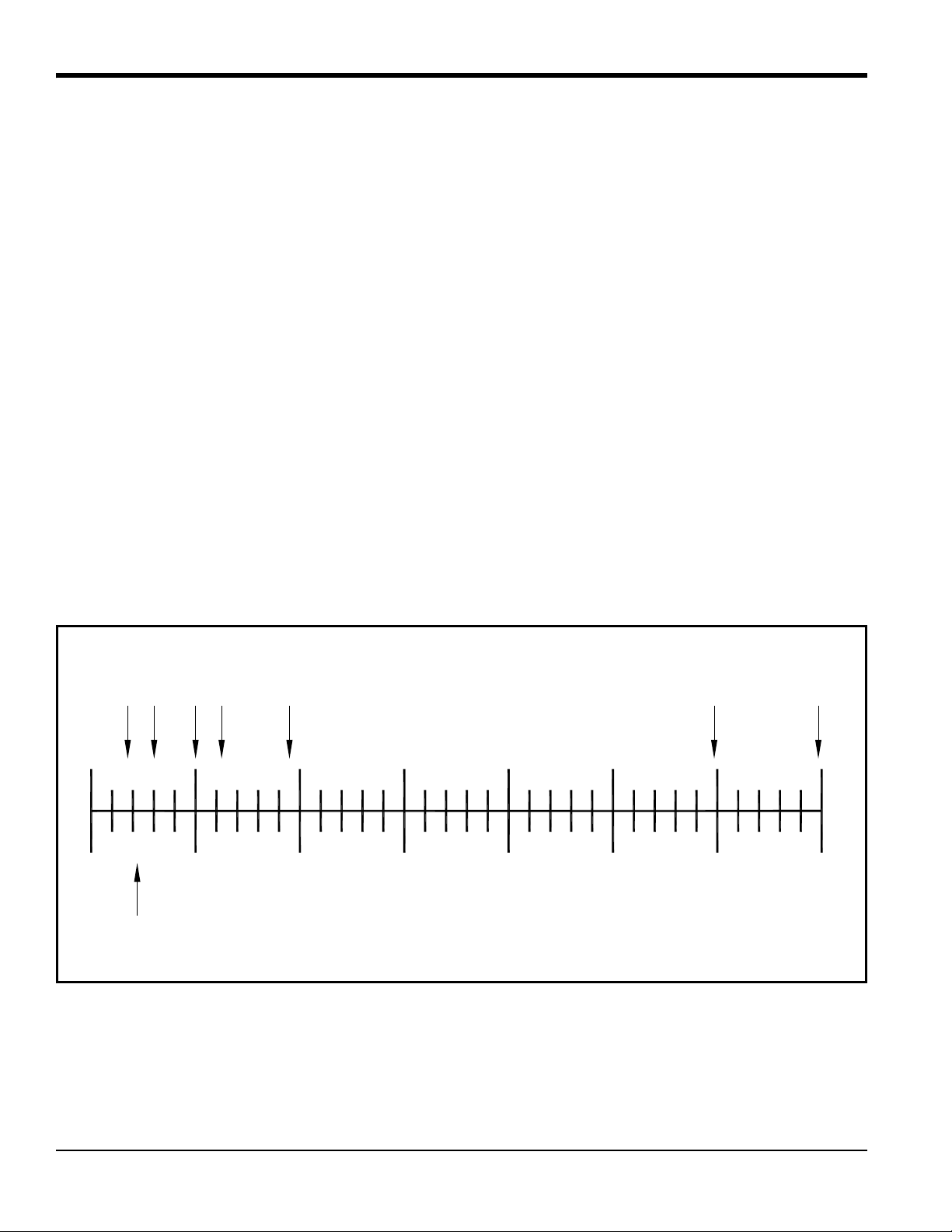
1.3 Theory of Operation
The XMTC measures the concentration of a gas in a binary gas mixture by measuring the thermal conductivity of the
sample gas and comparing it to the thermal conductivity of a selected reference gas.
Two ultra-stable, glass-coated thermistors are used: one in contact with the sample gas, and the other in contact with a
selected reference gas. The thermistors are mounted so that they are in close proximity to the stainless steel walls of the
sample chamber. The entire sensor is heated to 55°C/131°F, (or 70°C/158°F) and the thermistors are heated above the
sensor temperature using a constant current source. The thermistors lose heat to the walls of the sample chamber at a
rate that is proportional to the thermal conductivity of the gas surrounding them. Thus, each thermistor will reach a
different equilibrium temperature. The temperature difference between the two thermistors is detected in an electrical
bridge circuit. It is then amplified and converted to a 4-20 mA output proportional to the concentration of one of the
constituents of the binary gas mixture. For example:
• To measure 0 to 25% H
calibration, the zero gas would be 100% N
• To measure 90-100% H
the zero gas would be 90% H
Note: The XMTC has polarity adjustment jumpers which permit the measurement of gases (such as CO
relative thermal conductivity less than air/nitrogen.
Appendix A, Supplemental Information, contains a table of Relative Thermal Conductivity of Common Gases. Figure 1
below shows some of these values graphically.
in N2, the reference gas would be air (2-port version, sealed reference gas), and for
2
(i.e. 0% H2) and the span gas would be 25% H2 in N2.
2
in N2, the reference gas would be 100% H2 (4-port version, flowing reference gas),
2
in N2, and the span gas would be 100% H2 (the same as the reference gas).
2
) that have a
2
Figure 1: Relative Thermal Conductivity of Some Common Gases
2 XMTC User’s Manual
Page 13

Chapter 1. Features and Capabilities
1.4 System Description
The basic XMTC measurement system consists of an XMTC Transmitter mounted in a sample system. The sample
system is mandatory, and can either be provided by GE or constructed according to GE recommendations. The XMTC
is supplied with a standard 10 ft (3 m), 4-wire cable for power and output connections, with lengths up to 4000 ft
(1200 m) available. Optionally available from GE are a 24-VDC power supply to power the XMTC, a remote display
with programming and control capabilities, and several analyzers which can be interfaced with the XMTC.
1.4.1 Packaging and Temperature Rating
The XMTC transmitter is self-contained, consisting of the thermal conductivity sensor and associated electronics. It
requires 24 VDC power (1.2 A maximum at power-up), and provides a 4-20 mA output signal proportional to the
concentration of one of the gases in the binary sample gas mixture.
The XMTC is designed to be installed in a sample system as close as possible to the process sample point. Thus, it is
available in two environmental packages:
• Weatherproof
• Explosion-proof (with the addition of flame arrestors to the sample/reference gas inlet and outlet)
Each environmental package is available in a standard 2-port (sealed reference gas) version, or an optional 4-port
(flowing reference gas) version.
The XMTC is supplied with a standard measurement cell operating temperature of 55°C (131°F). An optional 70°C
(158°F) cell operating temperature is available.
Note: The 70°C (158°F) operating temperature should be selected only for high temperature applications, because it
results in reduced sensitivity.
XMTC User’s Manual 3
Page 14
Chapter 1. Features and Capabilities
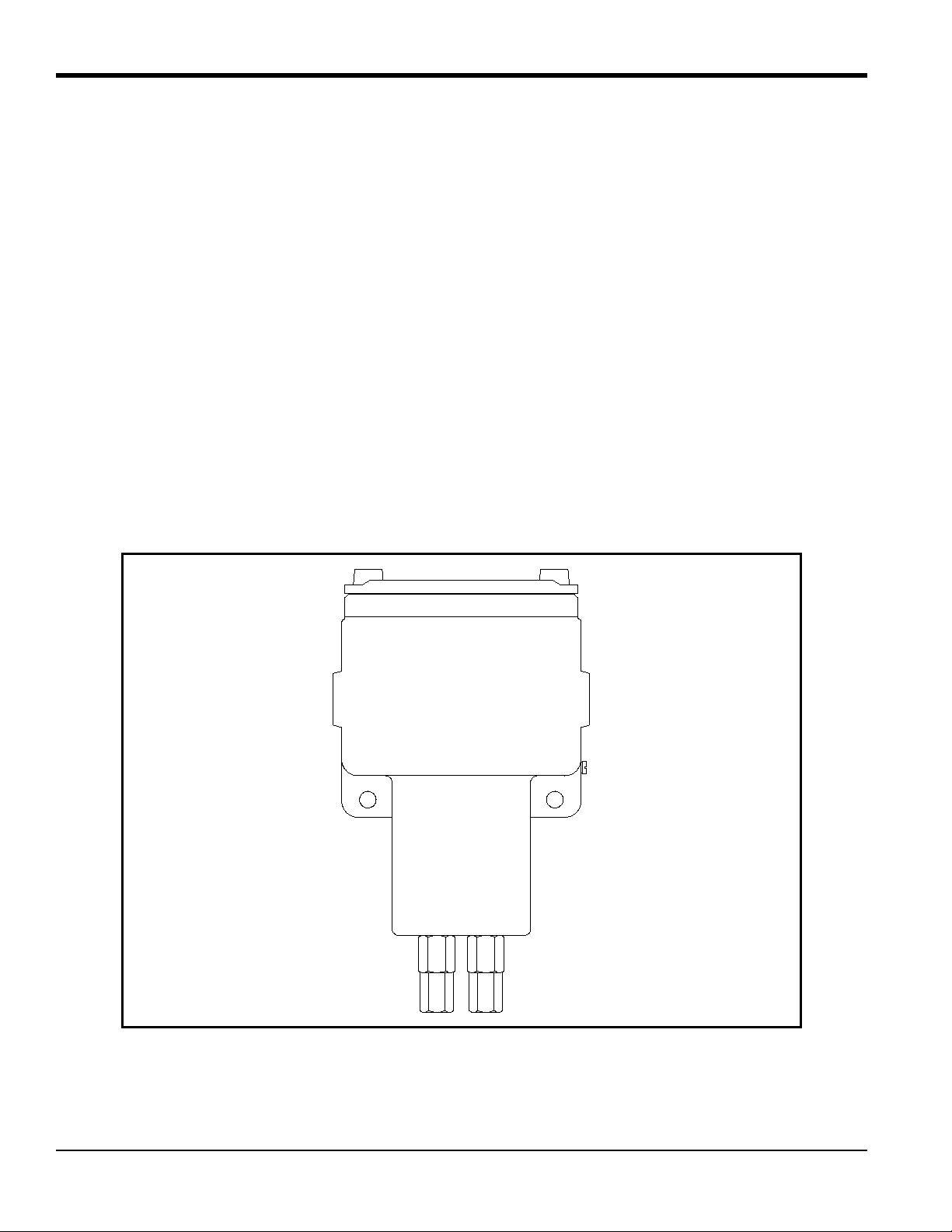
1.4.2 2-Port (Sealed Reference Gas) Version
This standard configuration (see Figure 2 below) is used for zero-based ranges with air or nitrogen at atmospheric
pressure as the balance or background gas. It utilizes air with desiccant in a factory sealed chamber as the reference gas.
The following standard ranges and gases are available:
Ranges: 0-2% Gases: H
0-5% CO
0-10% SO
0-25% He in N
0-50% Argon in N
0-100%
50-100%
80-100%
90-100%
95-100%
98-100%
in N2 or air
2
in N2 or air (min. range 0-5% CO2)
2
in air (min. range 0-2% SO2)
2
or air
2
or air
2
Figure 2: 2-Port (Sealed Reference Gas) XMTC
4 XMTC User’s Manual
Page 15
Chapter 1. Features and Capabilities
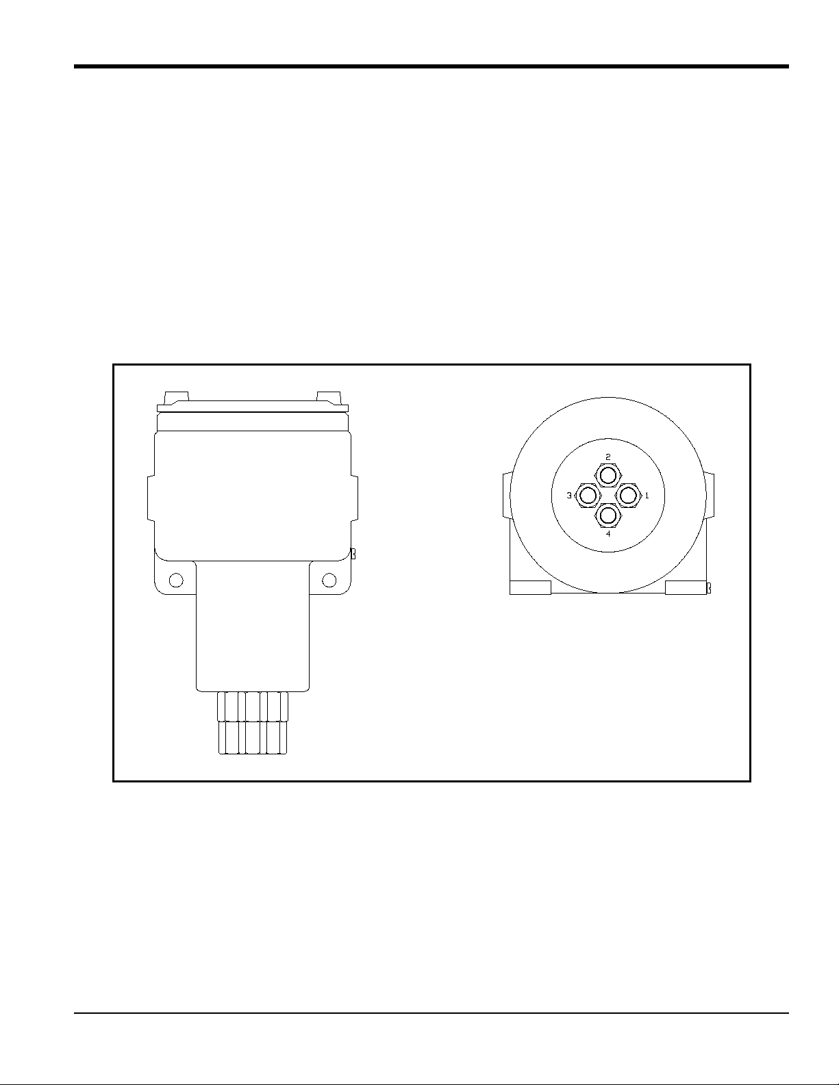
1.4.3 4-Port (Flowing Reference Gas) Version
This optional configuration shown in Figure 3 below is used for zero-suppressed ranges and some other special
applications. Typically, a flowing reference gas of 100% H
are available:
or CO2 is used. The following standard ranges and gases
2
Ranges: 90 to 100% Gases: H
in N
2
2
80 to 100% CO2 in N2 or air
He in N
or air
2
Note: For factory calibration pricing on the standard ranges and gases, or for pricing on other zero-suppressed
ranges and gases, please consult the factory.
Figure 3: 4-Port (Flowing Reference Gas) XMTC
XMTC User’s Manual 5
Page 16

Chapter 1. Features and Capabilities
1.4.4 Sample System
Use of a sample system is mandatory with the XMTC. The design of the sample system depends on the conditions of
the sample gas and the requirements of the application. In general, a sample system must deliver a clean, representative
sample to the XMTC at a temperature, pressure and flow rate that are within acceptable limits. Standard XMTC sample
conditions are as follows:
• Temperature less than 50
o
C (122oF) for 55oC cell operating temperature
• Atmospheric pressure
• Flow rate 0.5 SCFH (250 cc/min)
GE offers sample systems for a wide variety of applications. Two standard sample systems for the XMTC are shown in
Chapter 2, Installation. For assistance in designing your own sample system, please consult the factory.
1.4.5 Extra Cable (optional)
GE provides a 10 ft (3 m) length of 4-wire, color-coded cable with each XMTC to connect the power and outputs.
Optional cables are available in lengths up to 4000 ft (1200 m). If you are using your own cable, refer to Table 1 on
page 13 for recommendations.
1.4.6 Power Supply (optional)
The XMTC requires 24 VDC at a maximum start-up current of 1.2 A. The GE PS5R-C24 power supply converts
100/120/220/240 VAC to the required 24 VDC for the XMTC.
1.4.7 TMO2D-TC Display (optional)
The GE TMO2D-TC Display provides a two-line x 24 character back-lit LCD. It also features display and option
programming, recorder outputs, alarm relays, and relays for driving sample system solenoids for automatic zero and
span calibration of the XMTC. For information on the TMO2D-TC, please contact GE.
1.4.8 XDP Display (Optional)
The GE XDP Explosion-proof Display provides an integral, voltage-stabilized 24 VDC power supply, a 3-digit display
with adjustable 4-20 mA input range, two SPDT alarm relays rated for 1 A/250 VAC, and a 4-20 mA output that is
isolated from the input and adjustable to a second independent range if required. For information on the XDP, please
contact GE.
6 XMTC User’s Manual
Page 17

Chapter 1. Features and Capabilities
1.5 Typical Applications
The XMTC can be used in a wide variety of industrial applications where it is necessary to measure the concentration
of one component of a binary gas mixture. It can also be used in pseudo-binary gas mixtures where the ratio of
concentrations of the background gas components remains constant, and in gaseous mixtures where the thermal
conductivity of the gas of interest is significantly different from that of the background gas. Some typical industries and
applications include:
• Metals Industry -
H
in heat treat furnace atmospheres
2
• Electric Power Industry -
H
in generator cooling systems
2
• Gas Production Industry -
Purity monitoring of argon, hydrogen, nitrogen, helium
• Chemical Industry -
in ammonia synthesis gas
H
2
in methanol synthesis gas
H
2
in chlorine plants
H
2
• Food Industry -
in fermentation processes
CO
2
Ethylene Oxide (ETO) sterilization
• Steel Industry -
H
in blast furnace top gas
2
• Petroleum Industry -
H
in hydrocarbon streams
2
Two very common applications are:
• H
• H
For more details on these applications, refer to Appendix B, Applications. For details on applications not shown in
Appendix B, or if you wish to discuss your own application, please contact GE.
in N2 in heat treat furnace atmospheres: zero-based 0-25% H2, 2-Port (sealed reference gas, air)
2
purity in H2 electricity generator cooling: zero-suppressed, 80-100% H2, 4-Port (flowing reference gas,
2
100% H
)
2
XMTC User’s Manual 7
Page 18

Chapter 1. Features and Capabilities
[no content intended for this page]
8 XMTC User’s Manual
Page 19

Chapter 2. Installation
Chapter 2. Installation
2.1 Introduction
This chapter describes how to install the XMTC transmitter and its sample system. It also contains information on
connecting the XMTC to optional system components. The following topics are discussed:
• Mounting the XMTC transmitter
• Installing a GE sample system
• Wiring the XMTC transmitter
• Connecting the XMTC transmitter to optional components
2.2 Mounting the XMTC Transmitter
This section applies only if you are mounting the XMTC transmitter in a sample system that has not been supplied by
GE.
Your sample system should deliver a clean, representative sample to the XMTC at the proper temperature, pressure and
flow rate. This usually means a clean, dry sample (free of solid and liquid particulates) at atmospheric pressure; a
temperature no greater than 50°C (122°F); and a flow rate of approximately 0.5 SCFH (250 cc/min). Since factory
calibration of the sensor is at atmospheric pressure and 0.5 SCFH, higher or lower operating pressure may necessitate
field-calibration adjustment.
A simple sample system for a 2-Port XMTC might have inlet and outlet flow-regulating needle valves, a flow meter,
and a pressure gauge, in addition to the XMTC transmitter.
The XMTC transmitter should be mounted in the sample system so that it is upright and level to within ±15°. Also,
provide at least 9 in. (230 mm) of clearance above the top cover of the transmitter to allow access to the transmitter
printed circuit board (PCB) for calibration and maintenance. For a 2-Port XMTC, connect the sample system Sample
Inlet and Sample Outlet ports to the appropriate XMTC port. For a 4-Port system, also connect the Reference Inlet and
Reference Outlet ports to the appropriate XMTC ports.
Note: Refer to Appendix C, Installation and Wiring Diagrams, for port locations and other information.
WARNING! Be sure your installation conforms to all safety and electrical code requirements.
XMTC User’s Manual 9
Page 20
Chapter 2. Installation
SPAN GAS
INLET
9.00
(229.5)
(MIN)
TRANSMITTER
SAMPLE GAS
INLET
ZERO GAS
INLET
SAMPLE GAS
OUTLET
2.3 Mounting the Sample System
You can order a complete sample system from the factory. This includes the XMTC transmitter and all necessary
components and sample tubing mounted on a metal panel. Several standard sample systems are available, and
custom-designed sample systems can be built to your exact specifications.
Mount the sample system as close to the process sample point as possible. Once the sample system is mounted, connect
all inlet and outlet lines via the 1/4” compression fittings on the sample system. The sample line leading from the
process to the sample system should be of 1/4” stainless steel tubing, and should be as short as possible in order to
ensure a representative sample.
Following are descriptions of two standard sample systems:
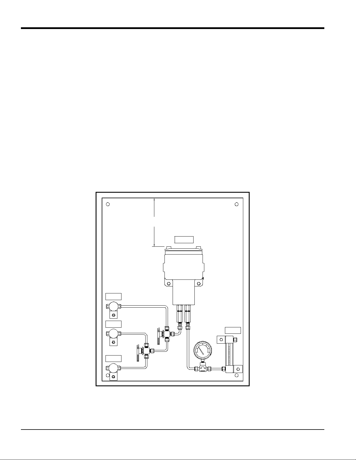
2.3.1 Manual, 2-Port (Sealed Reference Gas) Sample System
Figure 4 below shows a basic sample system for a 2-Port (sealed reference gas) XMTC. This sample system consists of
inlet needle valves for sample, zero, and span gases; a ball valve; a 2-port XMTC; a pressure gauge; and a flowmeter.
All components are mounted on a painted steel plate. Other components could be added for filtration (filter/coalescer),
pressure control (regulator), or flow control (pump).
Figure 4: Basic 2-Port Sample System (732-164)
10 XMTC User’s Manual
Page 21
Chapter 2. Installation
9.00
(229.5)
(MIN)
TRANSMITTER
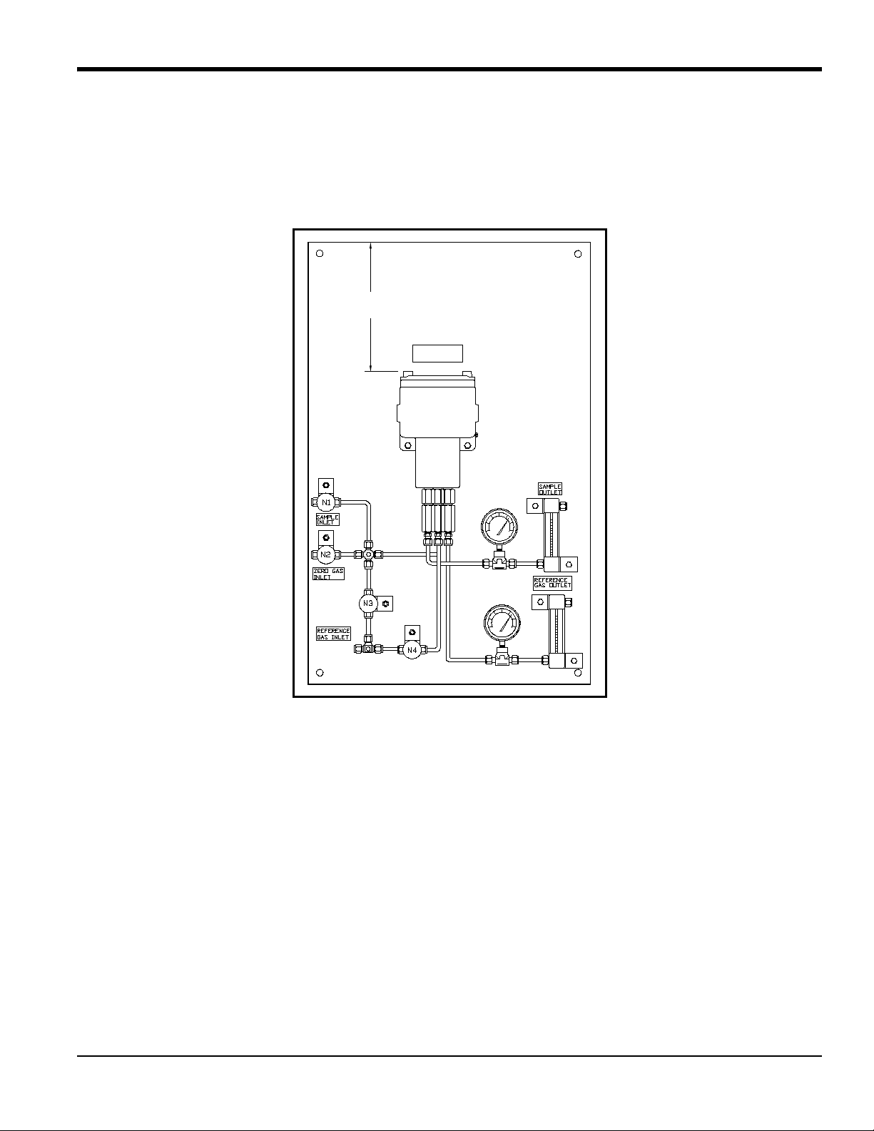
2.3.2 Manual, 4-Port (Flowing Reference Gas) Sample System
Figure 5 below shows a basic sample system for a 4-Port (flowing reference gas) XMTC. This sample system consists
of inlet needle valves for sample, reference, and calibration gases; a 4-port XMTC; two pressure gauges; and two flow
meters. All components are mounted on a painted steel plate. Other components could be added for filtration
(filter/coalescer), pressure control (regulator), or flow control (pump).
Figure 5: Basic 4-Port Sample System (732-028)
2.3.3 Sample Systems with Automatic Switching
Also available from GE are sample systems with electrically-actuated, three-way solenoid valves. When used in
conjunction with a TMO2D or XDP Display (with the Auto Cal option), these systems allow automatic switching of
sample, zero, span, and reference gases during operation and calibration. Refer to Appendix B, Applications, for details
on sample systems designed by GE for specific applications.
XMTC User’s Manual 11
Page 22

Chapter 2. Installation
External Ground Screw
2.4 Wiring the XMTC Transmitter
CAUTION! Always apply power to the XMTC immediately af ter installation, espe cially when it is
mounted outdoors or in a humid area.
This section describes how to wire the XMTC for 24 VDC power, RS232 communication, 4-20 mA output, and
optional devices.
2.4.1 Grounding the Enclosure
WARNING! The XMTC transmitter enclosure must be properly grounded.
Connect the external ground screw on the XMTC enclosure (see Figure 6 below) to a suitable earth ground.
Figure 6: Ground Screw Location
12 XMTC User’s Manual
Page 23

Chapter 2. Installation
2.4.2 CE Mark Compliance
WARNING! To meet CE Mark requirements, you must shield and ground all electrical cables as
described in Appendix E.
WARNING! CE Mark compliance is required for all units installed in EU countries.
WARNING! Cable entries of an approved flameproof design are required. These must be
installed according to the manufacturer’s instructions. The choice of cable entry device may limit
the overall installation category achieved.
2.4.3 Cable Specifications
Table 1 below shows the transmitter wiring connections for the standard GE XMTC cable, P/N X4(10). This cable can
be used for distances up to 4000 ft (1200 m).
Table 1: GE 4-Wire XMTC Cable
Lead Color AWG Terminal
+24 VDC Line Red 22 TB1-1
24 VDC Return Black 22 TB1-2
4-20 mA (+) White 22 TB1-3
4-20 mA (-) Green 22 TB1-4
If you are using your own cable to wire the XMTC, refer to Table 2 below for the cable requirements.
Table 2: Non-GE 4-Wire XMTC Cable
Maximum Cable Length Wire Size
ft m AWG mm
2
450 130 22 0.35
700 200 20 0.60
1,050 320 18 1.00
1,700 500 16 1.20
2,800 850 14 2.00
4,000 1,200 12 3.00
XMTC User’s Manual 13
Page 24
Chapter 2. Installation
TB1
TB2
SIGNAL CONNECTIONS
1
2
3
4
1
2
3
+24VDC Line (red) 1
24VDC Return (black) 2
+4 to 20 mA (white) 3
–4 to 20 mA (green) 4
RS232 RX (red) 1
RS232 TX (white) 2
RS232 GND (green) 3
2.4.3 Cable Specifications (cont.)
Table 3 below shows the connections for the GE standard 3-wire RS232 cable (P/N 704-668), which is available with a
male or female DB-9 or a DB-25 connector. This cable is available in standard lengths of 6 ft (2 m) and 12 ft (4 m).
Table 3: GE 3-Wire RS232 Cable
Lead Color AWG Terminal
RX Red 22 TB2-1
TX White 22 TB2-2
GND Green 22 TB2-3
Note: See EIA-RS Serial Communications (document 916-054) for detailed RS232 wiring instructions.
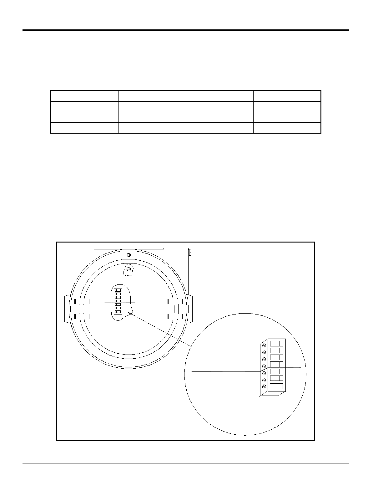
2.4.4 Wiring the Signal Connections
The XMTC power input, analog output, and RS232 connections are made to terminal blocks TB1 and TB2, which are
accessed by removing the XMTC cover. See Figure 7 below for the location and pin designations for terminal blocks
TB1 and TB2. Also refer to Appendix C, Installation and Wiring Diagrams.
CAUTION! Do not make any connections to unassigned or unused terminals.
Figure 7: XMTC Signal Wiring Connections
14 XMTC User’s Manual
Page 25

Chapter 2. Installation
2.4.4 Wiring the Signal Connections (cont.)
Use the following steps to make the proper wiring connections:
WARNING! Cable entries of an approved explosion-proof design are required. These must be
installed according to the manufacturer’s instructions. The choice of cable entry device may limit
the overall installation category achieved.
1. Install the selected cable entry device, such as conduit or seal-off, in accordance with the manufacturer’s
instructions.
Note: If installation of the cable entry device is only partially complete, GE recommends tagging the device to ensur e
the safety of subsequent users.
2. Route the cable into the XMTC.
3. Unplug the TB1 and TB2 connectors by pulling them straight off the PCB, and loosen the screws on the sides
of the connectors.
4. Connect the power leads:
CAUTION! Connecting the +24 VDC line (red) lead to any terminal except TB1-1 will damage
the XMTC.
a. Insert the 4-wire cable +24 VDC line (red) lead into pin TB1-1 and tighten the screw.
b. Insert the 4-wire cable 24 VDC return (black) lead into pin TB1-2 and tighten the screw.
5. Connec t the an alog output leads:
a. Insert the 4-wire cable + 4-20 mA (white) lead into pin TB1-3 and tighten the screw.
b. Insert the 4-wire cable – 4-20 mA (green) lead into pin TB1-4 and tighten the screw.
IMPORTANT: You can use either an RS232 serial port (discussed in Step 6) or an RS485 serial port (discussed in Step 7),
but not both.
6. Connect the RS232 serial port leads:
a. Insert the 3-wire cable RX (red) lead into pin TB2-1 and tighten the screw.
b. Insert the 3-wire cable TX (white) lead into pin TB2-2 and tighten the screw.
c. Insert the 3-wire cable GND (green) lead into pin TB2-3 and tighten the screw.
XMTC User’s Manual 15
Page 26
Chapter 2. Installation
Jumper J7
Jumper J8
RX 1
TX 2
GND 3
1 TD OUT
2
3
4 RD IN
XMTC (TB2) RS485 Converter
Red
White
Green
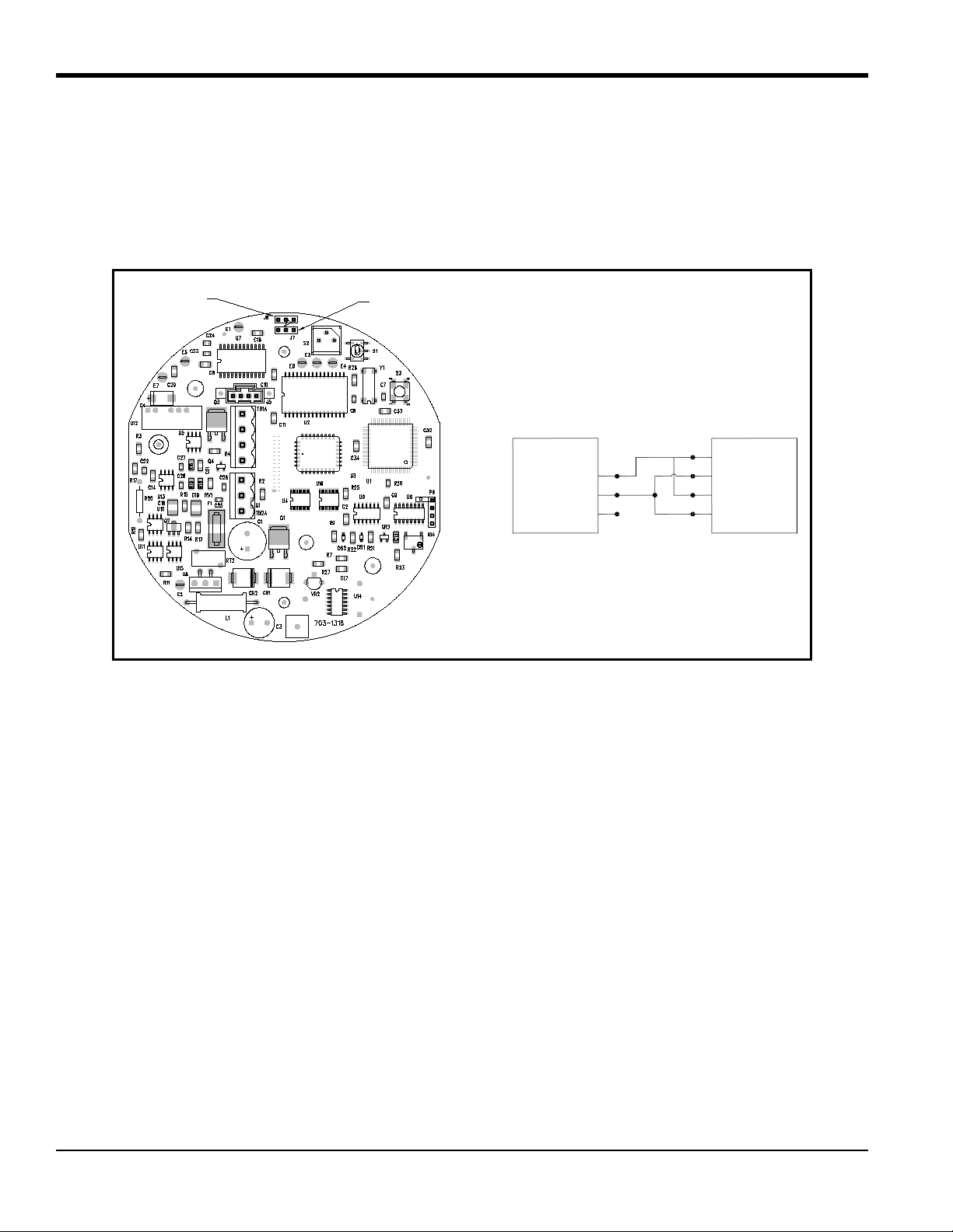
2.4.4 Wiring the Signal Connections (cont.)
7. Connect the RS485 serial port leads.
a. Locate the jumpers J7 and J8 on the main PCB, using Figure 8 below as a guide. Move the jumpers from
the left (RS232) side to the right (RS485) side.
b. Connect the other end of the cable to the RS485 converter, as shown in Figure 8 below.
Figure 8: Jumper Locations and RS485 Connections
8. Carefully plug the TB1 and TB2 connectors back onto the PCB, and reinstall the cover on the XMTC.
9. Connect the other ends of the cables to the 24 VDC power supply, the 4-20 mA input of the display device, and
the serial port of the computer or terminal (see the instruction manuals for those devices for details).
16 XMTC User’s Manual
Page 27
Chapter 2. Installation
Line
AC2
Neut
AC1
PS5R-C24
24 Volt
Power Supply
+24
VDC
GND
GND
GND
Neut
AC1
Line
AC2
AC Input
XMTC Transmitter
Red
Output
Device
Green
White
Black
TB1-1
+Vin
Black
TB1-2
RTN
White
TB1-3
4-20+
Green
TB1-4
4-20-
Red
TB2-1
RX
White
TB2-2
TX
Green
TB2-3
GND
RS232
Terminal
or PC
2.5 Connecting to Other Components
This section gives interconnection details for using other GE devices in conjunction with your XMTC.
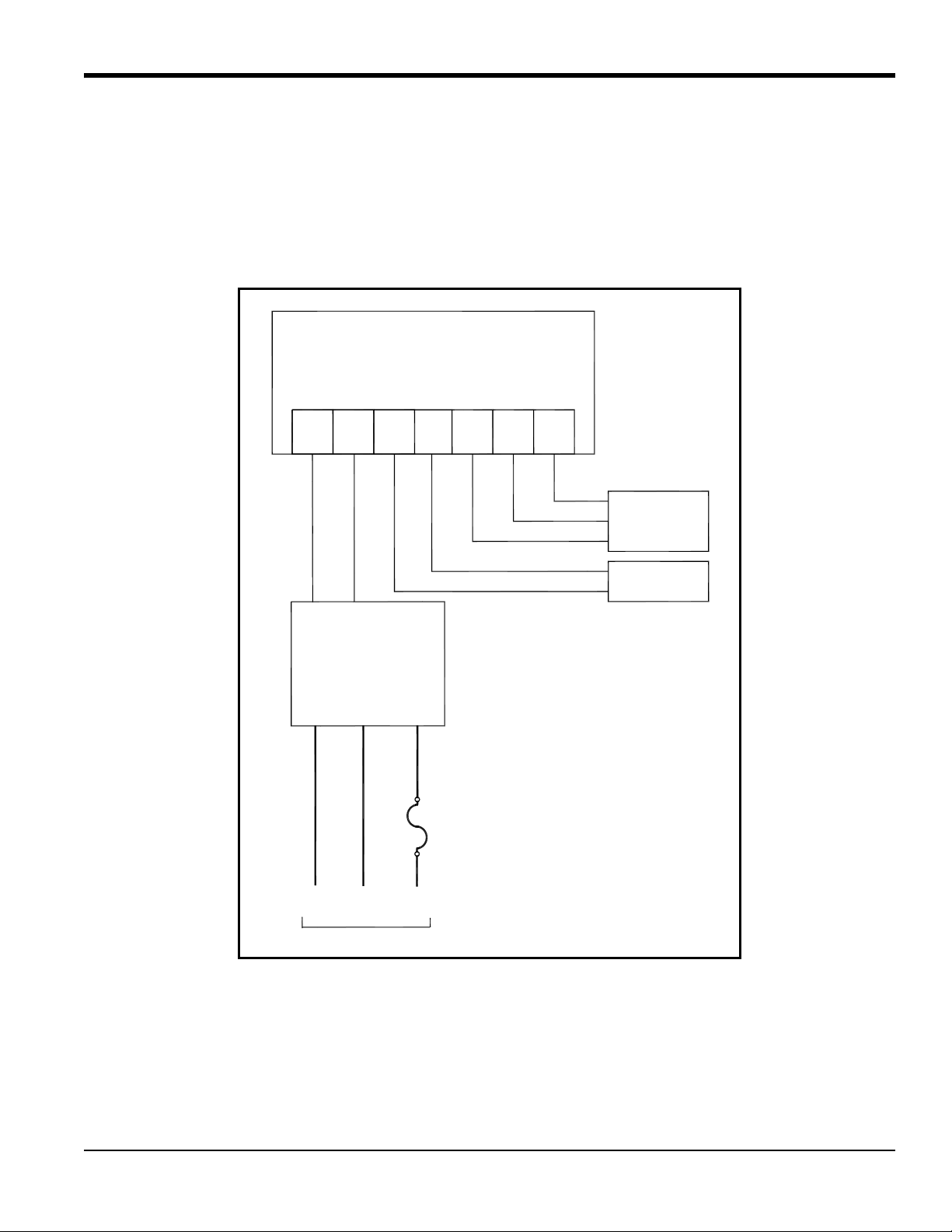
2.5.1 PS5R-C24 Power Supply
The GE 24-Volt power supply converts 100/120/220/240 VAC to 24 VDC for use with the XMTC. Figure 9 below
shows an interconnection diagram for the XMTC and the PS5R-C24 power supply.
Figure 9: Interconnection Diagram
XMTC User’s Manual 17
Page 28

Chapter 2. Installation
2.5.2 TMO2D Display
The GE TMO2D Display provides a two-line x 24 character back-lit LCD. It also features display and option
programming, recorder outputs, alarm relays, and optional relays for driving sample system solenoids for automatic
zero and span calibration of the XMTC. See Figure 72 on page 83 for an interconnection diagram for the XMTC and
the TMO2D, and refer to the TMO2D User’s Manual (910-084) for details on its operation.
2.5.3 XDP Display
The XDP Explosion-proof Display Package provides an integral, voltage-stabilized 24 VDC power supply, a 3-digit
display with adjustable 4-20 mA input range, two SPDT alarm relays rated for 1 A/250 VAC, and a 4-20 mA output
that is isolated from the input and adjustable to a second independent range if required. The XDP is supplied in a
weatherproof and explosion-proof enclosure that is rated for EEx d IIC T6 and IP66. See Figure 72 on page 83 for
interconnection diagrams for the XMTC and the MIS-1, MIS-2 and MMS-3 analyzers, and refer to the XDP User’s
Manual (910-204) for details on its operation.
2.5.4 Moisture Series Analyzers
The GE Moisture Image Series 1 (MIS-1) and Moisture Monitor Series 3 (MMS-3) analyzers accept inputs from a
variety of sensors (including the XMTC) and offer new graphical and digital user interfaces, improved performance,
and low range calibration. See Figure 72 on page 83 for interconnection diagrams for the XMTC and the MIS-1 and
MMS-3 analyzers, and refer to the appropriate User’s Manual for details on operating the MIS-1 (910-108) or MMS-3
(910-110) analyzer.
18 XMTC User’s Manual
Page 29

Chapter 3. Operation and Programming
Chapter 3. Operation and Programming
3.1 Introduction
This chapter provides information on operating the XMTC transmitter. The following topics are discussed:
• Powering up the XMTC
• Basic sample gas considerations
• Programming the XMTC with GE Instrument Data Manager (IDM™) software
If you have not already done so, please read Chapter 2, Installation, for details on mounting and wiring the XMTC and
the sample system.
3.2 Powering Up the XMTC
WARNING! It is the responsibility of the user to ensure that all cable entry devices and covers
are properly installed and secure prior to applying power to the XMTC.
The XMTC does not have a power switch. It begins operating as soon as it is connected to a 24 VDC power source.
Because the XMTC is controlled at a constant 55°C (131°F) operating temperature, allow 30 minutes for the unit to
warm up and reach temperature stability. During this time, you can establish a sample gas flow through the sample
system.
3.3 Starting the Sample Gas
Open the necessary valves to establish a sample gas flow of 0.5 SCFH (250 cc/min) at atmospheric pressure. Make sure
that nothing obstructs the flow of sample gas, thereby causing a pressure buildup in the sensing chamber. For proper
operation, the XMTC should be vented to atmosphere.
Note: Unless otherwise specified, the XMTC is factory calibrated at atmospheric pressure and 0.5 SCFH
(250 cc/min) and should therefore be operated at atmospheric pressure. Operating the XMTC at any other
pressure will necessitate a field calibration at that pressure in order to maintain accuracy. See Chapter 4,
Calibration, for more information.
If you are using the 4-Port (flowing reference gas) configuration, open the necessary valves to establish a reference gas
flow of 0.5 SCFH (250 cc/min) at atmospheric pressure.
Note: If desired, you can use a reference gas flow as low as 5 cc/min to conserve gas.
XMTC User’s Manual 19
Page 30

Chapter 3. Operation and Programming
3.4 Programming with IDM™
The XMTC is factory-programmed and ready for immediate use. However, if you wish to check or change the
calibration, you can access the XMTC programming from your PC, using GE Instrument Data Manager (IDM)
software. IDM also allows you to upload or download site files, display data, and log and view real-time data and
diagnostic data in numeric, bar chart or line chart formats. For further information on the display and logging functions,
refer to the Instrument Data Manager User’s Manual (910-185).
Note: Be sure to install Instrument Data Manager on your PC before attempting to program the XMTC.
3.5 The Edit Functions Menu
To access the XMTC calibration, you must open the Edit Functions menu in the Instrument window. See Chapter 5,
Using the Instrument Menu, in the Instrument Data Manager User’s Manual for more information on the Instrument
Menu. The menu consists of the five commands shown in Figure 10 below. To access a command, select it from the list
of options.
Note: While following the programming instructions, refer to Figure 51 on page 41 and Figure 52 on page 42.
Figure 10: Edit Functions Menu
Three buttons appear on the right side of all menu windows: Previous Item, Next Item/Enter, and Exit Page (see
Figure 11 on page 21):
• Clicking on Previous Item returns you to the previous window (either the command menu or the previous
parameter entered).
• Next Item/Enter confirms the selection or data entered, and either opens the next window or returns you to the
command menu (depending on your position in the program).
• Exit Page returns you to the command menu.
20 XMTC User’s Manual
Page 31

Chapter 3. Operation and Programming
3.6 Field Cal
When you select the Field Cal command, a window similar to the one in Figure 11 below opens.
Figure 11: Field Cal Window
The Field Cal command offers five options:
• Perform Cal — enables you to calibrate the XMTC with IDM
• Configure Cal — enables you to set the calibration type and parameters
• Calibration Drifts — indicates drift percentages for the zero and span gases
• Clear Calibration — enables you to clear the last calibration
• Hold Last Value — causes the XMTC to hold the last value calibrated.
Clicking on any option opens that option, while clicking on Next Item/Enter opens the menu listed on the status line
above the options.
3.6.1 Perform Cal
Click on Perform Cal to open a window similar to Figure 12 below.
Figure 12: Perform Cal Window
XMTC User’s Manual 21
Page 32

Chapter 3. Operation and Programming
3.6.1 Perform Cal (cont.)
Click on Zero Field Cal to calibrate the zero value, or on Span Field Cal to calibrate the span value. In either case, a
window similar to Figure 13 below opens.
Figure 13: Field Cal Execution Window
Click Yes to calibrate, or Abort Field Cal to stop the calibration and return to the previous menu. The result of a
completed calibration is shown in Figure 14 be low.
Figure 14: Field Cal Results Window
Click on Previous Item or on Next Item/Enter to return to the previous window, or on Exit Page to return to the
Instrument Menu.
22 XMTC User’s Manual
Page 33

Chapter 3. Operation and Programming
3.6.2 Configure Cal
The Configur e Cal comman d enables you to ch ange the field calibration type and parame ters: the percentage of zero or
span gas, delay time before or after, and maximum total drift and drift of calibration. When you click on Configur e Cal,
a window similar to Figure 15 below opens. Clicking on any option opens the window for that option, while clicking
on Next Item/Enter opens the menu listed on the status line above the options.
Figure 15: Configure Cal Window
3.6.2a Field Cal Type
The window for Field Cal Type is similar to Figure 16 below.
Figure 16: Field Cal Type Window
Click on 1 Point to select 1-Point (offset, or 1-gas) calibration, or on 2-Point to select 2-Point (zero/span, or 2-gas)
calibration. Then, click on any button on the right to return to the Configure Cal window.
XMTC User’s Manual 23
Page 34

Chapter 3. Operation and Programming
3.6.2b Field Cal Percent
The window for Field Cal Percent is similar to Figure 17 below.
Figure 17: Field Cal Percent Window
Click on Zero Field Cal to enter the zero percentage, or on Span Field Cal to enter the span percentage. In either case,
a window similar to Figure 18 below opens.
Figure 18: Gas Percentage Entry Window
T ype the desired percentage in the text box, and click Next Item/Enter to confirm the entry. (Click Previous Item or Exit
Page to close the window without changing the percentage.)
24 XMTC User’s Manual
Page 35

Chapter 3. Operation and Programming
3.6.2c Before Delay Time and After Delay Time
The windows for both Before Delay Time and After Delay Time are similar to Figure 19 below.
Figure 19: Before Delay Time Window
For either time, click on Zero Field Cal to enter the delay time for the zero calibration, or on Span Field Cal to enter the
time for the span calibration. A window similar to Figure 20 below opens.
Figure 20: Delay Time Entry Window
Enter the desired number of minutes and seconds in the text box, and click Next Item/Enter to confirm the entry. (Click
Previous Item or Exit Page to close the window without changing the percentage.) You are then returned to the
Configure Cal window.
XMTC User’s Manual 25
Page 36

Chapter 3. Operation and Programming
3.6.2d Max Total Drift and Max Drift/Cal
Max Total Drift is the maximum total drift allowable as a percentage of full scale, while Max Drift/Cal is the maximum
drift allowable per calibration as a percentage of full scale. The windows for both Max Total Drift and Max Drift/Cal
are similar to Figure 21 below.
Figure 21: Max Total Drift Entry Window
Enter the desired percentage of full scale in the text box, and click Next Item/Enter to confirm the entry . (Click Previous
Item or Exit Page to close the window without changing the percentage.) You are then returned to the Configure Cal
window.
3.6.3 Calibration Drifts
The Calibration Drifts command enables you to view the drift of both zero and span gases since the last calibration. A
window similar to Figure 22 below opens.
Figure 22: Calibration Drifts Window
Click on any button to return to the Field Cal window.
26 XMTC User’s Manual
Page 37

Chapter 3. Operation and Programming
3.6.4 Clear Calibration
The window for the Clear Calibration command is similar to Figure 23 below.
Figure 23: Clear Calibration Window
Click on Yes to clear the most recent calibration, or on No, Previous Item or Exit Page to close the window without
clearing the calibration. If you click on Yes and then on Next Item/Enter, a window similar to Figure 24 below open s.
Figure 24: Typical Cleared Calibration Window
Click on Previous Item to return to the Clear Calibration window, or on Next Item/Enter or Exit Page to return to the
Field Cal window.
3.6.5 Hold Last Value
Besides performing a calibration or configuring values, you can program the XMTC to hold the last calibrated value.
From the Field Cal window (see Figure 11 on page 21), click on Hold Last Value. The window remains the same,
except that the button changes to Disable Hold Last. Click Next Item/Enter to confirm the entry, or Previous Item or
Exit Page to close the window without changing the value.
XMTC User’s Manual 27
Page 38

Chapter 3. Operation and Programming
3.7 4-20 mA Output
The 4-20 mA Output command enables you to modify the output that the XMTC sends to an external device such as a
recorder or digital multimeter. When you click on the 4-20 mA Output command from the Edit Functions menu
(Figure 10 on page 20), a window similar to Figure 25 below opens. Clicking on any option opens the window for that
option, while clicking on Next Item/Enter opens the menu listed on the status line above the options.
Figure 25: 4-20 mA Output Window
3.7.1 4-20 mA Range
The window for 4-20 mA Range is similar to Figure 26 below.
Figure 26: 4 mA Output Gas Percentage Window
Enter the desired percentage of gas for the 4 mA output in the text box. Clicking on Next Item/Enter opens the window
for the 20 mA output, shown in Figure 27 on page 29.
28 XMTC User’s Manual
Page 39

Chapter 3. Operation and Programming
3.7.1 4-20 mA Range (cont.)
Figure 27: 20 mA Output Gas Percentage Window
Enter the desired percentage of gas for the 20 mA output, and click Next Item/Enter to confirm the entry. The next
prompt is: “Clamp 4-20 mA Output?” Click on either No or Yes from the drop-down menu. A clamped reading never
exceeds the programmed 4-20 mA output range, while a reading that is not clamped can display measurements outside
the programmed range. (Click Previous Item to return to the previous parameter or on Exit Page to close the window
without changing the percentage.) You are then returned to the 4-20 mA Output window.
3.7.2 4 and 20 mA Cal
To calibrate the 4 and 20 mA output signals, click on the 4 mA Cal and 20 mA Cal commands respectively. In either
case, a window similar to Figure 28 below opens.
Figure 28: 4 mA Signal Calibration Window
Clicking on the UP command increases the signal incrementally, while clicking on the DOWN command decreases it
incrementally . Clicking on Numeric Calibration opens a window similar to the one shown in Figure 29 on page 30.
XMTC User’s Manual 29
Page 40

Chapter 3. Operation and Programming
3.7.2 4 and 20 mA Cal (cont.)
Figure 29: Numeric Calibration Window
Enter the desired number in the text box and click on Next Item/En ter. (Click on Previous Item or Exit Page to clos e the
window without changing the signal.) You are then returned to the previous window. After you have calibrated the
desired input signal, click on STORE to save the entry, and on Next Item/Enter to confirm it. If the signal is not
satisfactory , click on ABORT. (Click Previous Item or Exit Page to close the window without changing the signal.) You
are then returned to the 4-20 mA Output window (see Figure 25 on page 28).
3.7.3 4-20 mA % Test
The window for 4-20 mA % Test is similar to Figure 30 below.
Figure 30: 4-20 mA% Test Window
Enter the desired percentage, and click on Next Item/Enter to confirm the entry . A secon d text box opens, enablin g you
to test at another percentage if desired. Repeat the procedure until you have entered all desired test values. Then click
Exit Page to close the window.
30 XMTC User’s Manual
Page 41

Chapter 3. Operation and Programming
3.7.4 % Gas Test
The window for % Gas Test is similar to Figure 31 below.
Figure 31: % Gas Test Window
Enter the desired percentage, and click on Next Item/Enter to confirm the entry . A secon d text box opens, enablin g you
to test at another percentage if desired. Repeat the procedure until you have entered all desired values. Then click Exit
Page to close the window.
3.8 Error Handler
The Error Handler command allows you to enable or disable error handling for specific error conditions for the
XMTC. When you click on the Error Handler command from the Edit Functions menu (Figure 10 on page 20), a
window similar to Figure 32 below opens. Clicking on any option opens the window for that option.
Figure 32: Error Handler Window
XMTC User’s Manual 31
Page 42

Chapter 3. Operation and Programming
3.8.1 Total Drift Error
The Total Drift Error option lets you enable or disable error handling for Total Drift Error. The window is similar to
Figure 33 below.
Figure 33: Total Drift Error Window
If you click on mA Enable, a window similar to Figure 34 below opens.
Figure 34: Error mA Output Window
Enter the desired error mA output in the text box, and click on Next Item/Enter to confirm the entry. You are then asked
for confirmation, as shown in Figure 35 on page 33.
32 XMTC User’s Manual
Page 43

Chapter 3. Operation and Programming
3.8.1 Total Drift Error (cont.)
Figure 35: IDM Enable/Disable Window
Click on IDM Enable to enable drift error. (Click Previous Item or Exit Page to close the window without changing the
output.) However , if you click on mA Disable, you are also asked for confirmation. Click on IDM Disable to disable the
drift error. You are then returned to the Error Handler window.
3.8.2 Drift/Cal Error
The DriftCal Err or option lets you enable o r disable error handling for DriftCal, generated when an error occurs during
calibration. The window is similar to Figure 36 below.
Figure 36: DriftCal Error Window
If you click on mA Enable, the window displays a text box similar to that in Figure 34 on page 32. Enter the desired
error mA output in the text box, and click on Next Item/Enter to confirm the entry. You are then asked for confirmation,
as shown in a window similar to Figure 35. Click on IDM Enable to enable drift error. (Click Previous Item or Exit
Page to close the window without changing the output.) However, if you click on mA Disable, you are also asked for
confirmation. Click on IDM Disable to disable the drift error. You are then returned to the Error Handler window.
XMTC User’s Manual 33
Page 44

Chapter 3. Operation and Programming
3.8.3 Gas mV Under/Over Range
The Gas mV Under Range and Gas mV Over Range options let you enable or disable error handling for the main gas
signal. The window is similar to Figure 37 below.
Figure 37: Gas mV Under Range Window
If you click on mA Enable, the window displays a text box. Enter the desired error mA output in the text box, and click
on Next Item/Enter to confirm the entry . You are then asked for confirmation. Click on IDM Enable to enable the under
or over-range error. (Click Previous Item or Exit Page to close the window without changing the output.) However, if
you click on mA Disable, you must confirm the choice in a second window. Click on IDM Disable to disable the under
or over-range error. You are then returned to the Error Handler window.
3.8.4 Gas % Under/Over Range
The Gas % Under Range and Gas % Over Range options let you enable or disable error handling for the main gas
percentage. The window is similar to Figure 38 below.
Figure 38: Gas % Under Range Window
If you click on mA Enable, the window displays a text box. Enter the desired error mA output in the text box, and click
on Next Item/Enter to confirm the entry. Then click on IDM Enable to enable the under or over-range error. (Click
Previous Item or Exit Page to close the window without changing the output.) However, if you click on mA Disable,
you must confirm the choice in a second window. Click on IDM Disable to disable the under or over-range error. You
are then returned to the Error Handler window.
34 XMTC User’s Manual
Page 45

Chapter 3. Operation and Programming
3.9 Factory Cal
The XMTC comes completely preprogrammed from the factory for your particular application. Should it become
necessary to reprogram the meter, you can use the Factory Cal option.
IMPORTANT: Do not use the Factory Cal option without referring to the Calibration Data Sheet enclosed with your
XMTC. Varying from the parameters on the sheet can result in problems with the XMTC and other
equipment.
From the Edit Functions menu (shown in Figure 10 on page 20), click on the Factory Cal option. A window similar to
Figure 39 below opens.
Figure 39: Factory Cal Window
The option permits you to edit the number of points and the value of each individual point.
3.9.1 Edit # of Points
To edit the number of available points, click on Edit # of Points. A window similar to Figure 40 below opens.
Figure 40: Edit # of Points Window
Click on Add once for each point you wish to add, or on Delete once for each point you wish to remove. Then click on
Next Item/Enter to confirm the entry. (Click Previous Item or Exit Page to close the window without changing the
number of points.) You are then returned to the Factory Cal window, which displays the new number of points.
XMTC User’s Manual 35
Page 46

Chapter 3. Operation and Programming
3.9.2 Edit Point X
T o edit the value for any particular point, click on that point in the Fa ctory Cal window. A window similar to Figure 41
below opens.
Figure 41: Point Editing Window
Enter the gas percentage in the text box, and click on Next Item/Enter to confirm the entry. (Click Pr evious Item or Exit
Page to close the window without changing the value.) Then, enter the next value, as shown in Figure 42 below.
Figure 42: Additional Values for Point 1
Enter the x01 and x10 Gas mV values, and click on Next Item/Enter af ter each entry. After you have completed entering
values, you are returned to the Factory Cal window.
36 XMTC User’s Manual
Page 47

Chapter 3. Operation and Programming
3.10 The Advanced Option
IMPORTANT: Access to this menu is password-protected. Your assigned default password = 2719.
The final option on the Edit Functions menu is Advanced, an option that allows you to choose between Fast Response
and Language response. In addition, you can add or change the meter identification number.
Note: For other available commands in the Advanced Option, refer to Appendix D.
From the Edit Functions menu (Figure 10 on page 20), click on Advanced to open a window similar to Figure 43
below. Then, enter your password.
Figure 43: Password Window
After you have entered the password, an Advanced window similar to Figure 44 below opens.
Figure 44: Advanced Window
Fast Response is software-enhanced response for faster performance under certain conditions, while Language
response enables you to upload data to or download data from a PC. Meter ID enables you to enter or change a meter
network identification number. Click on the desired comman d. (Click Previous Item or Exit Page to close the window
without entering any commands.)
XMTC User’s Manual 37
Page 48

Chapter 3. Operation and Programming
3.10.1 Fast Response
If you click on Fast Response, confirm the choice to open a window similar to Figure 45 below.
Figure 45: Fast Response Confirmation Window
Click Yes to enable Fast Response. In the series of three text boxes that follow, enter values for the Fast Tau up, Fast
Tau down, and Fast Threshold % FS parameters. Then, click on Next Item/Enter to confirm the entry and open the next
window.
IMPORTANT: Do not change the default values for these parameters without consulting the factory.
3.10.2 Language
If you click on Language, a window similar to Figure 46 below opens.
Figure 46: Language Window
38 XMTC User’s Manual
Page 49

Chapter 3. Operation and Programming
3.10.2 Language (cont.)
If you click on Upload to PC, you are prompted to create a file, as shown in Figure 47 below.
Figure 47: Creating a Data File
If you click on Download from PC, you are asked for a file name, as shown in Figure 48 below.
Figure 48: Downloading a Data File
However, if you click on Reset to Defaults, the status is displayed in the Language window. Click on Next Item/Enter to
confirm the entry. (Click Previous Item or Exit Page to close the window without changing the status.)
XMTC User’s Manual 39
Page 50

Chapter 3. Operation and Programming
3.10.3 Meter ID
The Meter ID window is similar to Figure 49 below.
Figure 49: Meter ID Window
Either leave the existing number without change, or enter a new meter ID number. In either case, click Next Item/Enter
to confirm the entry . (Click Previous Item or Exit Page to close the window without changing the number.) If you have
changed an existing ID number, a window similar to Figure 50 below opens.
Figure 50: Revised Meter ID Window
IMPORTANT: After you have entered a new ID number, you cannot reverse the change. You must exit the page, close the
connection, and reconnect the meter using the new number.
Click on Next Item/Enter or Exit Page to return to the Advanced window.
40 XMTC User’s Manual
Page 51

IDM
Data
Global
Help
...More OpƟons...
Connect to a...
Edit FuncƟons
Upload/Download
Real-Time
System
NOTE: Click [Exit Page] or [Previous Item] at any Ɵme to abort the current operaƟon.
NoYes
[Next Item]
4-20mA Range
[Next Item]
Clamp 4-20mA Out?
Field Cal
4-20mA Output
[Next Item]
4-20mA % Test
[Next Item]
% Gas Test
[Exit Page]
4mA Cal 20mA Cal
4/20mA UP 4/20mA DOWN
Numeric CalibraƟon
4/20mA STORE 4/20mA ABORT
[click to increment value]
[Next Item]
[Next Item] [Next Item]
Zero Field Cal
Span Field Cal
[Next Item]
Perform Cal
Yes
Abort Field Cal
DriŌ OK!
ConĮgure Cal
Clear CaiibraƟon Hold Last Value
Hold Last Value
[Next Item]
NoYes
Field Cal Type
Field Cal Percent
Before Delay Time AŌer Delay Time
Max Total driŌ
Max DriŌ/Cal
[Next Item]
Zero Field Cal
Span Field Cal
[Next Item]
1 Point (Oīset)
2 Point (Z/S)
[Next Item]
Zero Field Cal
Span Field Cal
[Next Item]
Menu Item
Command Menu OpƟon
Data Entry Window
[Previous Item]
Return to Previous Window
[Next Item/Enter]
ConĮrm/Accept Current Entry
[Exit Page]
Return to Command Menu
KEY/LEGEND
Chapter 3. Operation and Programming
Figure 51: Field Cal and 4-20mA Output Menu Map
XMTC User’s Manual 41
Page 52

IDM
Data
Global
Help
...More OpƟons...
Connect to a...
Edit FuncƟons
Upload/Download
Real-Time
System
Error Handler
Factory Cal
Edit Point X
Edit # of Points
Delete
Add
% Gas
[Next Item]
[Next Item]
x01 Gas mV
[Next Item]
x10 Gas mV
[Next Item]
Advanced
Language
Fast Response
Password
Meter ID
Number
[Next Item]
NoYes
Fast Tau Up
[Next Item]
Fast Tau Down
[Next Item]
Fast Threshold %FS
[Next Item]
Download from PC
Upload to PC
Reset to Defaults
Filename
[Next Item]
Gas mV under range
DriŌ/Cal Err
Gas mV over range
Total DriŌ Error
Gas % under range
Gas % over range
mA Enable mA Disable
Set Error mA Output
[Next Item]
IDM Enable IDM Disable
NOTE: Click [Exit Page] or [Previous Item] at any Ɵme to abort the current operaƟon.
Menu Item
Command Menu OpƟon
Data Entry Window
[Previous Item]
Return to Previous Window
[Next Item/Enter]
ConĮrm/Accept Current Entry
[Exit Page]
Return to Command Menu
KEY/LEGEND
Chapter 3. Operation and Programming
Figure 52: Error Handler, Factory Cal and Advanced Menu Map
XMTC User’s Manual 42
Page 53

Chapter 4. Calibration
Chapter 4. Calibration
4.1 Introduction
This chapter provides information on calibrating the XMTC in the field using zero, span, and reference gases. The
following topics are discussed:
• General considerations for calibration at the factory and in the field
• What you will need before you begin calibrating
• Getting the XMTC ready and locating the adjustment potentiometers
• Calibrating the 2-Port (sealed reference gas) XMTC with zero and span gases
• Calibrating the 4-Port (flowing reference gas) XMTC with zero, span, and reference gases
4.2 Gas Ranges and Types
The XMTC was calibrated at the factory for the range and gas mixture specified at the time of purchase. The following
standard ranges and gases are provided:
Ranges: 0-2% Gases: H
0-5% He in Air
0-10% He in N
0-25% CH4 in CO2 (minimum range 0-10% CH4)
0-50% CO
0-100% CO
50-100%
80-100%
90-100%
95-100%
98-100%
Note: Calibrations can be performed for special ranges and gases upon request.
The XMTC requires recalibration every 2 to 6 months, depending on the application. The exact calibration interval will
depend on such factors as: components of the binary gas mixture, desired accuracy, range, and cleanliness of the
sample gas. You can recalibrate the XMTC for the same range and binary gas mixture as the previous calibration using
just the zero and span adjustments.
in N
2
2
2
in Air (minimum range 0-20% CO2)
2
in N2 (minimum range 0-20% CO2)
2
XMTC User’s Manual 43
Page 54

Chapter 4. Calibration
4.3 Required Equipment and Materials
WARNING! The calibration procedure described in this section requires the use of specialized
apparatus and should be performed only by properly trained personnel.
To calibrate the XMTC, you will need the following equipment and materials:
• XMTC Calibration Sheet
• +24 VDC, 1.2 A power supply (system power, if unit is installed in a system)
• Zero gas
• Span gas
• Reference gas (for the 4-Port version - the reference gas is usually the same as the span gas.)
• Sample system or individual components (e.g. flow meter, needle valve, pressure regulator) for connecting
zero and span gases and controlling pressure and flow rates
Note: The accuracy of the calibration will only be as accurate as the composition accuracy of the zero and span
gases.
WARNING! Do not use explosive gas mixtures to calibrate the XMTC.
44 XMTC User’s Manual
Page 55

Chapter 4. Calibration
Set Screw
Cover
4.4 Preparing the Transmitter for Calibration
Complete the following steps before connecting and adjusting the zero, span, and reference gases:
1. Allow 30 minutes after power is turned on for the XMTC to reach temperature stability.
2. Loosen the set screw that locks the XMTC cover in place, and unscrew the cover (see Figure 53 below).
Figure 53: Transmitter Cover and Set Screw
XMTC User’s Manual 45
Page 56

Chapter 4. Calibration
Cal Button (S3)
Zero and Span Adjustment (S1)
4.4 Preparing the Transmitter for Calibration (cont.)
3. The XMTC printed circuit board (PCB) is located directly below the cover. Locate the switches S1 (zero and
span adjustment) and S3 (calibration button) using Figure 54 below as a guide.
Figure 54: Calibration Switch Locations
4.5 2-Port (Sealed Reference Gas) Calibration
1. Connect the XMTC Sample Inlet to the zero gas via the Zero Gas Inlet on the sample system or other gas
control system.
2. Establish a flow rate of 0.5 SCFH (250 cc/min) of zero gas at 0.0 psig to the XMTC.
3. Allow 2-5 minutes for the reading to settle. Move S1 to the zero position (marked on the PCB). Press S3 (the
calibration button) for about 20 seconds.
4. Connect the XMTC Sample Inlet to the span gas via the Span Gas Inlet on the sample system or other gas
control system.
5. Establish a flow rate of 0.5 SCFH (250 cc/min) of span gas at 0.0 psig to the XMTC.
6. Allow 2-5 minutes for the reading to settle. Move S1 to the span position (marked on the PCB). Press S3 (the
calibration button) for about 20 seconds.
46 XMTC User’s Manual
Page 57

Chapter 4. Calibration
4.6 4-Port (Flowing Reference Gas) Calibration
1. Connect the XMTC Reference Inlet to the reference (span) gas via the Reference Gas Inlet on the sample
system or other gas control system.
2. Establish a flow rate of 0.5 SCFH (250 cc/min) of reference (span) gas at 0.0 psig to the XMTC Reference
Inlet.
Note: You can use a calibration gas flow rate as low as 5 cc/min to conserve gas.
3. Connect the XMTC Sample Inlet to the zero gas via the Zero Gas Inlet on the sample system or other gas
control system.
4. Establish a flow rate of 0.5 SCFH (250 cc/min) of zero gas at 0.0 psig to the XMTC Sample Inlet.
5. Allow 2-5 minutes for the reading to settle. Move S1 to the zero position (marked on the PCB). Press S3 (the
calibration button) for about 20 seconds.
6. Connect the XMTC Sample Inlet to the span gas via the Span Gas Inlet on the sample system or other gas
control system.
7. Establish a flow rate of 0.5 SCFH (250 cc/min) of span gas at 0.0 psig to the XMTC Sample Inlet.
8. Allow 2-5 minutes for the reading to settle. Move S1 to the span position (marked on the PCB). Press S3 (the
calibration button) for about 20 seconds.
XMTC User’s Manual 47
Page 58

Chapter 4. Calibration
[no content intended for this page]
48 XMTC User’s Manual
Page 59

Chapter 5. Specifications
5.1 Performance
Accuracy ±2% of span
Linearity ±1% of span
Repeatability ±0.5% of span
Stability Zero: ±0.5% of span per week
Span: ±0.5% of span per week
Response Time 20 seconds for 90% of step change
Chapter 5. Specifications
Measurement Ranges
(typical)
0-2%
0-5%
0-10%
0-25%
0-50%
0-100%
50-100%
80-100%
90-100%
95-100%
98-100%
Measurement Gases
(typical)
H
in N
2
air or CO
2,
2
He in N2 or Air
in N2 or Air (minimum range 0-20% CO2)
CO
2
in Air (minimum range 0-10% SO2)
SO
2
Ar in N
or air (minimum range 0-20% argon)
2
Ambient Temperature Effect ±0.05% of span per °C
Required Sample Gas
0.1 to 4.0 SCFH (5 to 2000 cc/min), 0.5 SCFH (250 cc/min) nominal
Flow Rate
Required Reference Gas
0.01 to 4.0 SCFH (5 to 2,000 cc/min), 0.5 SCFH (250 cc/min) nominal
Flow Rate
XMTC User’s Manual 49
Page 60

Chapter 5. Specifications
5.2 Functional
Analog Output 4-20 mA isolated, 800 ohm max, field-programmable
Power 24 VDC ±2 VDC, 1.2 A maximum
Cable 10 ft (3 m), 4-wire; lengths up to 4000 ft. (1200 m) available
Operating Temperature
Standard: +55
Optional: +70°C (+158
o
C (+131oF)
o
F)
Ambient Temperature Range Standard cell operating temperature (55°): -20° to +45°C (-4° to +104°F)
Optional cell operating temperature (70°): +5° to +60°C (+41° to +140°F)
5.3 Physical
Sensor Wetted Materials Standard: 316 SS, glass, and Viton™ o-rings
Optional: Hastelloy C276, Titanium and Chemraz™ o-rings
Dimensions Weatherproof unit: 9.54” (H) x 5.70” (D) (242 x 145 mm)
Explosion-proof unit: 10.48” (H) x 5.70” (D) (266 x 145 mm)
Weight 9.5 lb (4.3 kg)
Connections Electrical conduit: 3/4” NPTF
Sample inlet/outlet, optional reference inlet/outlet: 1/4” NPTF
Environmental Weatherproof: Class I Div. 1 Groups A, B, C & D
Class II, III Div. 1 Groups E, F & G
Tamb 65°C T5 Type 4X
Flameproof: ITS12ATEX17703X
IECEx ITS 12.0058X
II 2 G Ex d IIC T6 Gb
IP66 -20°C < Tamb < +65°C
All conduit entries 3/4” NPT
CE: EMC 2004/108/EC
PED 97/23/EC
Note: For CE compliance, the power and I/O cables must be shielded. All cables
must be terminated within the cable gland at the XMTC.
Note: See the Certification Drawings in Appendix C, Installation and Wiring
Diagrams, for additional details.
50 XMTC User’s Manual
Page 61

5.4 Accessories
The following accessories are available for use with the XMTC:
• PS5R-C24 - 24 VDC power supply
• X4 (*) - 4-wire cable (X specifies length), lengths up to 4000 ft (1200 m) are available
• TMO2D - display/control module
• MIS-1 and MMS-3 - graphical moisture, temperature, oxygen and thermal conductivity analyzers
• XDP - explosion-proof display package
• 704-668-12 - RS232 cable, 12 ft (4 m) length with DB-9 female connector
• IDM - manual and software with floppy disk (part number 910-185)
• PanaView - interface software manual and CD (part number 910-211)
Chapter 5. Specifications
XMTC User’s Manual 51
Page 62

Chapter 5. Specifications
[no content intended for this page]
52 XMTC User’s Manual
Page 63

Appendix A. Supplemental Information
A.1 Ordering Information
ABCDE
XMTC – –
B - Measuring Cell Package*
1. Weatherproof enclosure, sealed reference (2-port), CPVC cell
2. Explosion-proof enclosure, sealed reference (2-port), CPVC cell
3. Weatherproof enclosure, flowing reference (4-port) CPVC cell
4. Explosion-proof enclosure, flowing reference (4-port) CPVC cell
5. Weatherproof enclosure, sealed reference (2-port) FEP-coated aluminum cell*
6. Explosion-proof enclosure, sealed reference (2-port) FEP-coated aluminum cell*
Appendix A. Supplemental Information
W. Without enclosure, sealed reference (2-port), FEP-coated aluminum cell
X. Without enclosure, sealed reference (2-port), CPVC cell
Y. Without enclosure, flowing reference (4-port), CPVC cell
*Standard measuring cell package is FEP coated aluminum cell — see options 5 and 6 above.
C - CE Compliance
2.Standard
C. CE Compliant
D - Certification Label for Explosion-Proof Options
1. T6 rating label, for ambient temperatures up to 55°C
2. T5 rating label, for ambient temperatures up to 65°C
E - Wetted Material
1. 316 Stainless Steel/Viton O rings
2. Hastelloy C276/Chemraz O rings
XMTC User’s Manual 53
Page 64

Appendix A. Supplemental Information
A.2 Calibration Specification Ordering Information
ABC
XMTC-CAL –
B - Cell Range
2. 0 to 2%
3. 0 to 5%
4. 0 to 10%
6. 0 to 25%
7. 0 to 50%
8. 0 to 100%
A. 90 to 100%
B. 80 to 100%
C. 50 to 100%
D. 98 to 100%
E. 95 to 100%
S. Special
C - Standard Gases
1. H
in N
2
2
2. CO2 in N2 (minimum range 0 to 20% CO2)
3. CO
4. He in N
in Air (minimum range 0 to 20% CO2)
2
2
5. He in Air
6. Calibration for H
7. CH
in CO2 (minimum range 0 to 10% CH4)
4
cooled generators H2/CO2/Air
2
S. Special
Note: Binary gas composition must total 100%.
54 XMTC User’s Manual
Page 65

Appendix A. Supplemental Information
A.3 XMTC PCB Subassemblies
703-1276-02 XMTC transmitter analog PCB assembly
707-320 XMTC instrument program
703-1316-03 XMTC transmitter digital PCB assembly compatible with IDM communications software
910-185 Instrument Data Manager software and manual (supplied on floppy disk)
CREDIT-XMTC Trade-in credit for uncontaminated XMTC. Partial credit to be determined after receipt and upon
inspection at the factory.
XMTC User’s Manual 55
Page 66

Appendix A. Supplemental Information
XMTC Calibration Sheet
XMTC S/N: 2630
XMTC Part Number: XMTC-62-11
Calibration Part Number: XMTC-CAL-311
Calibration Gases: H2/N2
Calibration Ranges: 0 to 5%
Work Order Number: 508230006418
Calibration Date: April 24, 2009
Technician: K. Brin
Unit Calibrated Using x10 Gain Scale
XMTC Calibration Data
Hydrogen in Nitrogen
PT %H2 x10 (mV) Output (mA)
1 0.00 -56.02 4.00
2 5.00 574.00 20.00
Output:
4 to 20 mA 0 to 5% H2 in N2
Clamp Output:
No
Field Calibration.
Zero:
100% N2
Span:
5% H2 in N2
A.4 Sample Calibration Sheet
A typical calibration sheet example is shown in Figure 55 below.
56 XMTC User’s Manual
Figure 55: A Sample Calibration Sheet
Page 67

Appendix A. Supplemental Information
A.5 Relative Thermal Conductivity of Common Gases
Table 4: Thermal Conductivity of Common Gases
Gas Temperature = 0
Air, N2/O
Hydrogen, H
Helium, He 5.970 5.530
Nitrogen, N
Oxygen, O
Neon, Ne 1.900 1.840
Argon, Ar 0.677 0.665
Chlorine, Cl
Carbon Monoxide, CO 0.962 0.958
Carbon Dioxide, CO
Nitric Oxide, NO 0.980 0.978
Sulfur Dioxide, SO
Hydrogen Sulfide, H
Carbon Disulfide, CS
Ammonia, NH
Water Vapor, H
Methane, CH
Ethane, C
Propane, C
n-Butane, C
Isobutane, C
n-Pentane, C
Isopentane, C
n-Hexane, C
n-Heptane, C
Cyclohexane, C
Ethylene, C
Propylene, C
Acetylene, C
1,3 Butadiene, C
Nitrous Oxide, N
Ethylene Oxide, C
Ethyl Alcohol, C
Isopropyl Alcohol*, C3H7OH
Acetone, C
Methyl Chloride, CH
Ethyl Chloride, C
Vinyl Chloride, C
Freon-11, CCl
Freon-12, CCl
Freon-22, CHClF
Freon-113, C
Hydrogen Chloride, HCl 0.520 0.517
Hydrogen Fluoride, HF 0.654 0.959
2
2
2
2
2
2
2
S 0.538 0.562
2
2
3
O 0.755 0.771
2
4
2H6
3H8
4H10
4H10
5H12
5H12
6H14
7H16
6H12
2H4
3H6
2H2
4H6
O 0.633 0.762
2
O 0.469 0.620
2H4
OH 0.590 0.685
2H5
O 0.406 0.557
3H6
Cl 0.377 0.530
3
Cl 0.391 0.540
2H5
Cl 0.443 0.551
2H3
F 0.286 0.368
3
2F2
2
2Cl3F3
*Consult GE
o
C (32 oF) Temperature = 100oC (212oF)
1.000 1.000
6.968 6.803
1.000 0.989
1.018 1.028
0.323 0.340
0.603 0.704
0.350 0.381
0.285 0.300
0.897 1.040
1.250 1.450
0.750 0.970
0.615 0.832
0.552 0.744
0.569 0.776
0.535 0.702
0.515 0.702
0.508 0.662
0.399 0.582
0.375 0.576
0.720 0.980
0.626 0.879
0.770 0.900
0.441 0.642
0.492 0.644
0.344 0.442
0.388 0.474
0.277 0.369
XMTC User’s Manual 57
Page 68

Appendix A. Supplemental Information
[no content intended for this page]
58 XMTC User’s Manual
Page 69

Appendix B. Typical Applications
INPUT
OUTLET
SAMPLE
OUTPUT
INLET
SPAN GAS
INLET
ZERO GAS
INLET
SAMPLE
N2
N1
N3
N4
Appendix B. Typical Applications
B.1 H2 in N2 in Heat Treat Furnace Atmospheres
The XMTC can be used to measure the concentration of hydrogen (H2) in nitrogen (N2) in a heat treat furnace
atmosphere.
B.1.1 Problem
Mixtures of H2 and N2 are used as controlled atmospheres in the heat treating of metals. These mixtures are
well-defined and need to be maintained in order to assure product quality and consistency. Dissociated ammonia is one
such atmosphere. Here, ammonia is broken down into free N
B.1.2 Equipment
A typical instrumentation package includes a 2-port (Sealed Reference Gas - air) XMTC transmitter with a 4-20 mA
range of 0-25% H
often specified.
mounted in a sample system similar to the one shown in Figure 56 below. A display package is
2
and H2 in a 25 to 75% mixture.
2
Figure 56: Sample System
XMTC User’s Manual 59
Page 70

Appendix B. Typical Applications
XMTC CALIBRATION SHEET
THERMAL CONDUCTIVITY TRANSMITTER
Serial Number TC-102
Part Number XMTC-22-2
Range, % 0 to 25% H
2
Output 4 to 20 mA
PC Board 703-1095
Work Order: PCI 90403
Calibration Date: September 18, 2000
Point %H
2
* H2, mA
1 0.00 4.00
2 25.00 20.00
*Calibration is with Hydrogen (H
2
) in Nitrogen (N2)
B.1.2 Equipment (cont.)
The sample system consists of needle valves for selection and isolation of sample, zero, and span gases, a needle valve
for flow control, a filter/coalescer, a 2-port XMTC transmitter, a pressure gauge, a flowmeter, and a sample pump. All
components are mounted on a painted steel plate.
Note: A TMO2D or XDP display package is typically used. A GE moisture analyzer can be used when the H
2
measurement is to be made in conjunction with a moisture measurement.
B.1.3 Basic Operating Procedure
The H2 content is continuously monitored at the inlet, hot zone, and/or effluent of the furnace. A sample gas flow rate
of 0.5 SCFH (250 cc/min) is established. The sample system should be located in an area cooler than 50
the tubing leading to the sample system should be at least 5 ft (1.5 m) long to insure proper cooling of the sample gas.
For this application the required calibration gases are:
• Zero gas - N
• Span gas - 10.0 or 25.0% H
(99.95 % minimum purity)
2
in N2, or H2 (99.95 % minimum purity)
2
A typical XMTC Calibration Data Sheet is shown in Figure 57 below.
o
C (122oF), and
Figure 57: A Typical XMTC Calibration Data Sheet
60 XMTC User’s Manual
Page 71

Appendix B. Typical Applications
B.1.4 Permanent Installation
Continuous monitoring of the furnace atmosphere H2 content using the XMTC assures a high degree of quality control
in the manufacturing process.
B.1.5 Specifications
Typical Ranges:
0 to 10% H
0 to 25% H2 in N
0 to 100% H2 in N
Operating Conditions:
Pressure: Ambient
Temperature: +540 to +1370
in N
2
2
2
2
o
C (+1000 to +2500oF)
B.1.6 Detailed Operating Procedure
The following procedure details the start-up, operation, and calibration of the 2-port (Sealed Reference Gas) XMTC
sample system for heat treat furnace applications shown in Figure 56 on page 59.
Needle valves N1 through N4 on the sample system drawing have the following functions:
• N1 – selects/isolates the process sample gas
• N2 – selects/isolates the calibration zero gas
• N3 – selects/isolates the calibration span gas
• N4 – controls the flow of the selected gas
XMTC User’s Manual 61
Page 72

Appendix B. Typical Applications
B.1.6a Start-up
1. Mount the sample system in an enclosed area heated to a temperature above 0oC.
2. Make sure that all needle valves are fully closed.
3. Run 1/4” tubing from the process to N1 (Sample Inlet).
Note: If the process is at a high pressure, a pressure regulator should be placed before this valve.
CAUTION! The XMTC is calibrated and intended for use at atmospheric pressure. Higher
pressures will lead to inaccurate readings, may result in damage to the instrument, and/or may
pose a safety problem.
4. Run 1/4” tubin g from the pressure regul ator on the cylinder containing the zero calibration gas to N2 ( Zer o Gas
Inlet).
5. Run 1/4” tubing from the pressure regulator on the cylinder containing the span calibration gas to N3 (Span
Gas Inlet).
Note: No pressure restrictions should be placed on the pump outlet. Any tubing on the outlet should be at least 1/4”
in diameter, and preferably 1/2”.
6. Leak test all sample system fittings, as well as those leading to the sample system.
7. Bring 24 VDC to the XMTC. Refer to Chapter 2, Installation, and allow 1 hour before proceeding.
8. Bring 120 VAC to the sample pump.
9. Open N4 one turn.
10. Fully open N1.
11. Adjust N4 until the flowmeter reads mid-scale. The pressure gauge should read 0 psig.
After the system has come to equilibrium, the sample system should be checked periodically to ensure that there is gas
flow through the flowmeter.
62 XMTC User’s Manual
Page 73

Appendix B. Typical Applications
B.1.6b Calibration
Refer to Chapter 4, Calibration, for the complete XMTC calibration procedure. The procedures below are only a
supplement to that procedure. These procedures show the valve configurations necessary to deliver the calibration
gases to the XMTC.
Zero Gas Calibration:
1. Fully clos e N1 .
2. Fully open N2.
3. Adjust N4 until the flowmeter reads mid-scale. The pressure gauge should read 0 psig.
Allow enough time for the tubing to be cleared of the sample gas before making any adjustments to the transmitter.
Span Gas Calibration:
1. Fully close N2 (or N1).
2. Fully open N3.
3. Adjust N4 until the flowmeter reads mid-scale. The pressure gauge should read 0 psig.
Allow enough time for the tubing to be cleared of the zero (or sample) gas before making any adjustments to the
transmitter.
Returning to Standard Operation:
1. Fully close N3 (or N2).
2. Fully open N1.
3. Adjust N4 until the flow meter reads mid-scale. The pressure gauge should read 0 psig.
After the system has come to equilibrium, the sample system should be checked periodically to insure that there is flow
through the flow meter.
XMTC User’s Manual 63
Page 74

Appendix B. Typical Applications
REFERENCE
SAMPLE
OUTLET
INLET
SAMPLE
REFERENCE
GAS INLET
GAS OUTLET
ZERO GAS
INLET
N1
N2
N3
N4
9.00
(229.5)
(MIN)
TRANSMITTER
B.2 H2 Purity in H2-Cooled Electricity Generator
The XMTC can be used to measure the purity of hydrogen (H2) in hydrogen-cooled electricity generators used in the
power industry.
B.2.1 Problem
H2 is used as a cooling medium in electricity generators because of its high thermal conductivity. If air leaks into the
, the mixture can become explosive.
H
2
B.2.2 Equipment
A typical instrumentation package includes a 4-port (Flowing Reference Gas - hydrogen), explosion-proo f XMTC
transmitter with a 4-20 mA range of 80 to 100% H
below. An XDP display package is often specified.
mounted in a sample system similar to the one shown in Figure 58
2
Figure 58: Sample System (732-028)
64 XMTC User’s Manual
Page 75

Appendix B. Typical Applications
XM TC CALIB R ATION SHEET
T HERMAL CONDUCT IVITY TRANSM ITT ER
XMTC Transmi tter
Serial Number TC-135
Part Number XMTC-42-1
Range, % 80 to 100% H
2
in N
2
Output 4 to 20 mA
PC Board 703-1095
Work Order: PCI 94445
Calibration Date: September 1, 2000
Point %H
2
* H2, mA
1 80.00 4.00
2 90.00 11.62
3 100.00 20.00
*Calibration is with Hydrogen (H
2
) in Nitrogen (N2)
B.2.2 Equipment (cont.)
The sample system consists of inlet needle valves for sample, zero, span, and reference gases; a 4-port explosion-proof
XMTC; two pressure gauges; and two flowmeters. All components are mounted on a painted steel plate. A pump may
be needed to draw a sample through the sample system.
Note: A TMO2D or XDP display package is typically used. A GE moisture analyzer display package can be used
when the H
measurement is to be made in conjunction with a moisture measurement.
2
B.2.3 Basic Operating Procedure
The H2 purity is continuously monitored at the generator. A sample gas flow of 0.5 SCFH (250 cc/min) is established.
A hydrogen reference gas flow of 0.4 SCFH (200 cc/min) is sufficient for proper operation. The sample system should
o
be located in an area cooler than 50
(1.5 m) long to insure proper cooling of the sample gas.
For this application the required calibration gases are as follows:
C (122oF), and the tubing leading to the sample system should be at least 5 ft
• Zero gas - 80.0% H
• Span gas - H
2
in N
2
2
(minimum 99.95 % purity)
• Reference gas - same as span gas
A typical XMTC Calibration Data Sheet is shown in Figure 59 below.
Figure 59: Typical XMTC Calibration Data Sheet
XMTC User’s Manual 65
Page 76

Appendix B. Typical Applications
B.2.4 How Previously Handled
The system (generator) was leak checked periodically. If a leak occurred between checks, an explosion could occur.
Moisture analyzers were also used for continuous analysis, since the presence of moisture in the H
of an air leak.
is indirect evidence
2
B.2.5 Permanent Installation
Continuous monitoring of the generator H2 purity using the XMTC provides increased safety. A low H2 reading alerts
plant personnel to a potential safety problem and allows them to locate the leak and correct the problem.
B.2.6 Specifications
Range:
80 to 100% H
Operating Conditions:
Pressure: 0.5 to 75 psig
Temperature: +30° to +50
in N
2
2
o
C (+86 to +122oF)
B.2.7 Detailed Operating Procedure
The following procedure details the start-up, operation, and calibration of the 4-port (Flowing Reference Gas) XMTC
sample system for the hydrogen purity applications shown in Figure 58 on page 64.
Needle valves N1 through N4 on the sample system drawing have the following functions:
• N1 – controls the flow of the process sample gas
• N2 – controls the flow of the zero calibration gas
• N3 – controls the flow of the span calibration gas
• N4 – controls the flow of the reference gas
66 XMTC User’s Manual
Page 77

Appendix B. Typical Applications
B.2.7a Start-up
1. Mount the sample system in an enclosed area heated to a temperature above 0oC.
2. Make sure that all needle valves are fully closed.
3. Run 1/4” tubing from the process to N1 (Sample Inlet).
Note: If the process is at a high pressure, a pressure regulator should be placed before this valve.
CAUTION! The XMTC is calibrated and intended for use at atmospheric pressure. Higher
pressures will lead to inaccurate readings, may result in damage to the instrument, and/or may
pose a safety problem.
4. Run 1/4” tubin g from the pressure regul ator on the cylinder containing the zero calibration gas to N2 ( Zer o Gas
Inlet).
5. Run 1/4” tubing from the pressure regulator on the cylinder containing the span calibration gas/reference gas to
N4 (Reference Gas Inlet).
Note: No pressur e restrictions should be placed on the flowmeter outlets. Any tubing on the outlets should be at least
1/4” in diameter, and preferably 1/2”.
6. Leak test all sample system fittings, as well as those leading to the sample system.
7. Bring 24 VDC to the XMTC. Refer to Chapter 2, Installation, and allow 1 hour before proceeding.
8. Slowly open N1 until the sample outlet flowmeter reads mid-scale. The pressure gauge at the sample outlet
should read 0 psig.
9. Slowly open N4 until the reference gas outlet flowmeter reads mid-scale. The pressure gauge at the reference
gas outlet should read 0 psig.
After the system has come to equilibrium, the sample system should be checked periodically to insure that there is gas
flow through both flowmeters.
XMTC User’s Manual 67
Page 78

Appendix B. Typical Applications
B.2.7b Calibration
Refer to Chapter 4, Calibration, for the complete XMTC calibration procedure. The procedures below are only a
supplement to that procedure. These procedures show the valve configurations necessary to bring the calibration gases
to the XMTC.
Zero Gas Calibration:
1. Fully clos e N1 and / or N3.
2. Slowly open N2 until the sample outlet flowmeter reads mid-scale. The pressure gauge at the sample outlet
should read 0 psig.
Note: If N3 was closed in this step and if the flow in the reference gas outlet flowmeter increased when N3 was
closed, adjust N4 to bring the flow to mid-scale.
Allow enough time for the tubing to be cleared of the sample gas or calibration span gas before making any
adjustments to the transmitter.
Span Gas Calibration:
1. Fully clos e N1 and / or N2.
2. Slowly open N3 until the sample outlet flowmeter reads mid-scale. The pressure gauge at the sample outlet
should read 0 psig.
Note: If the flow in the refer ence gas outlet flowmeter decr eased when N3 was opened, adjust N4 to bring the flow to
mid-scale.
Returning to Standard Operation:
1. Fully clos e N2 and / or N3.
Note: If N3 was closed in this step and if the flow in the reference gas outlet flowmeter increased when N3 was
closed, adjust N4 to bring the reference gas flow to mid-scale.
2. Slowly open N1 until the sample outlet flowmeter reads mid-scale. The pressure gauge at the sample outlet
should read 0 psig.
After the system has come to equilibrium, the sample system should be checked periodically to insure that there is flow
through both flow meters.
68 XMTC User’s Manual
Page 79

Appendix C. Installation and Wiring Diagrams
Appendix C. Installation and Wiring Diagrams
This appendix includes the following XMTC drawings in 11” x 17” fold-out format:
• Figure 60, “Certification Drawing (ref. 752-168, Rev. E. SH1),” on page 71
• Figure 61, “Certification Drawing (ref, 752-168, Rev. E, SH2),” on page 72
• Figure 62, “Certification Drawing (ref. 752-168, Rev. E, SH4),” on page 73
• Figure 63, “Analog PCB Schematic (ref. 700-1276, Rev. F, SH1),” on page 74
• Figure 64, “Analog PCB Schematic (ref. 700-1276, Rev, F, SH2),” on page 75
• Figure 65, “Digital PCB Schematic (ref. 700-1316, Rev. H, SH1),” on page 76
• Figure 66, “Digital PCB Schematic (ref. 700-1316, Rev. H, SH2),” on page 77
• Figure 67, “EMI Filter PCB Schematic (ref. 700-1550, Rev. A),” on page 78
• Figure 68, “Analog PCB Assembly (ref. 703-1276, Rev. H),” on page 79
• Figure 69, “Digital PCB Assembly (ref. 703-1316, Rev. K, SH1),” on page 80
• Figure 70, “Digital PCB Assembly (ref. 703-1316, Rev. K, SH2),” on page 81
• Figure 71, “EMI Filter PCB Assembly (ref. 703-1550, Rev. A, SH1 & SH2),” on page 82
• Figure 72, “XMTC Interconnection Diagrams,” on page 83
XMTC User’s Manual 69
Page 80

[no content intended for this page]
70 XMTC User’s Manual
Page 81

C-C NOITCES
CC
6,5 DEVOMER DNA 4,3,2,1 STEEHS DETADPU ,OCE REP DETADPU
.cnI,gnisneSerutcurtsafnIEG
evirDkraPygolonhceT0011
ASU12810,AMacirelliB
ROTSERRA EMALF ,U2000.21 ENI xECEI & U31009XETA21 SIRENI
.11
ECNARAELC DNA EGAPEERC NI 52.0 ERIUQER SLANIMRET GNIRIW DLEIF
.8
YLLACINAHCEM ,KCIHT 020. ETALP GNITNUOM LEBAL .ON LAIRES DNA LEDOM
.DERUCES YLLACINAHCEM ,MUNIMULA KCIHT 020. :LAIRETAM LEBAL REZYLANA
ETISOPPO FO SLANIMRET DNA GNIRIW DLEIF TIUCRIC YLPPUS NEEWTEB
EHT DNA SLANIMRET GNIRIW DLEIF TIUCRIC YLPPUS DNA YTIRALOP
DEGAGNE YLLUF 8
MUMINIM SDAERHT
ø
2.041
OSI 3/569 2x421M
DAERHT CIRTEM
GNIR-O
81.1
0.03
.ERUSOLCNE
.9
.01
.DERUCES
PIT ENOC mm8 x 5M
WERCS TES DAEH TEKCOS
ø
25.5
.SELOH DELLIRD LLA
.mm2.0 FO SSENKCIHT MUMIXAM A HTIW 8307 LAR -TAOC REDWOP DERUTXET :HSINIF
DEWOLLA GNINIHCAM RO SELOH LANOITIDDA
ON
AID mm 021 x KHT mm 35.3 LAES FOORP REHTAEW ROF GNIR-O
DNUORA/REDNU DERIUQER LAIRETAM ESAC SSECXE mm3
.STTAW 52 DEECXE OT TON NOITAPASSID REWOP LANRETNI
.3
.2
.5
.6
.7
.4
861-257
CTMX,2OMX
ERIUQERGNIWARDSIHTOTSEGNAHC
.NOITAZIROHTUAYCNEGAROIRP
REENIGNENOITACIFITRECEHTTCATNOC
GNIWARDNOITACIFITREC
.DERIUQER TON STSET ERUSSERP ENITUOR .ERUSSERP NOITPMEXE CITATSORDYH STEEM
:SETON
) LA = REDNIAMER ,%5.0 = nM ,%53.0 = gM ,%9 = iS ( ERUSOLCNE MUNIMULA :LAIRETAM
,%35.0=uC ,%50.2=oM%5.61=rC ,%07.1=nM ,%54.0=iS ,%110.O=C ( ERUSOLCNE LEETS SSELNIATS
) eF = REDNIAMER ,%460.0=N ,%620.0=S ,%82.0=P ,%2.01=iN
.1
OCE REP DETADPU Aver861-257 MORF NEKAT
B
30/52/8
FCJ
9885
6&,5,4,3,2 STEEHS DETADPU
72050
6&,5,4,3 STEEHS DETADPU ,OCE REP DETADPU
C
40/12/1
FCJ
29150
30/92/8
GJ
30/4/9
FWP
40/72/1
GJ
40/72/1
FWP
40/1/21
NR
D
92450
6&,5,4,3 STEEHS DETADPU ,OCE REP DETADPU
JADFWP
40/2/21
40/2/21
E
21/1/21
21/1/21
21/1/21
SPJGK
SPJ
36480
.ONLEDOM
NR
SNOITPIRCSED
SNOISIVER
OCEVER NWDDKCDVPA
DACOTUA
D
Appendix C. Installation and Wiring Diagrams
Figure 60: Certification Drawing (ref. 752-168, Rev. E. SH1)
XMTC User’s Manual 71
Page 82

Appendix C. Installation and Wiring Diagrams
D
20/31/60GJ
20/81/60FMP20/62/40ALR
861-257
ERIUQERGNIWARDSIHTOTSEGNAHC
.NOITAZIROHTUAYCNEGAROIRP
REENIGNENOITACIFITRECEHTTCATNOC
A-ANOITCES
Figure 61: Certification Drawing (ref, 752-168, Rev. E, SH2)
XMTC User’s Manual 72
Page 83

Appendix C. Installation and Wiring Diagrams
ERIUQERGNIWARDSIHTOTSEGNAHC
.NOITAZIROHTUAYCNEGAROIRP
REENIGNENOITACIFITRECEHTTCATNOC
NOISREVCTMX
20-
60-
40-
80-
:etaD .gfM
gnisneS EG
tsaE enoZ eerF
dnalerI ,nonnahS
gnisneS EG
tsaE enoZ eerF
dnalerI ,nonnahS
06 revo stneibma nI
º
09 rof detar eriw dleif esu C
º
.nim C
66PI
56 bmaT
º
C
X4 epyT
96.57
52.
PYT
39.43
52.
PYT
78.7
PYT
99.81
PYT
50.3
SCLP 4
.SCLP 4
38.1 AID
39.1 AID
R
03.3
SCLP 4
00.76
PYT
gnisneS ,erutcurtsarfnI EG
.rD kraP ygolonhceT 0011
ASU 12810 AM ,acirell
iB
era srotserra emalf fi dioV :noituaC
negyxo rof devorppA .devomer
.tnecrep 52 ot pu snoitartnecnoc
slaes tiudnoc eriuqer snoitallatsni ASC
.sehcni 81 nihtiw
D&,C,B,A PG 1 VID I LC
G&,F,E PG ,1 VID III,II LC
X4 epyT 5T C 56 bmaT
º
®
devorppA
:etaD .gfM
gnisneS ,erutcurtsarfnI EG
.rD kraP ygolonhceT 0011
ASU 12810 AM ,acirelliB
06 revo stneibma nI
º
09 rof detar eriw dleif esu C
º
.nim C
66PI
56 bmaT
º
C
X4 epyT
devorppA
®
0811
sttaW 52 CDV 42
rezylanA saG CTMX
0811
sttaW 52 CDV 42
rezylanA saG CTMX
0811
sttaW 52 CDV 42
rezylanA saG CTMX
0811
sttaW 52 CDV 42
rezylanA saG CTMX
X30771XETA21STI
X8500.21 STI xECEI
bG 6T CII d xE G 2 II
02- 66PI
TPN "4/3 SEIRTNE TIUDNOC LLA
ºº
C56+ <bmaT< C
X30771XETA21STI
X8500.21 STI xECEI
bG 6T CII d xE G 2 II
02- 66PI
TPN "4/3 SEIRTNE TIUDNOC
LLA
ºº
C56+ <bmaT< C
RP NOISLO NOISREV FOO
E
LPLXEBA
RP NOISLO NOISREV FOO
E
LPLXEBA
D
861-257
tneserp si erehp
somta evisolpxe na nehw
nepo ton oD
tneserp si erehpsomta evisolpxe na nehw nepo ton o
D
LEBAL NOISREV FOORPREHTAEW
LEBAL NOISREV FOORPREHTAEW
NOISREV ASU
NOISREV ASU
NOISREV DNALERI
NOISREV DNALERI
Figure 62: Certification Drawing (ref. 752-168, Rev. E, SH4)
XMTC User’s Manual 73
Page 84

Appendix C. Installation and Wiring Diagrams
TABLE 3
GROUPS
NUMBER
DESCRIPTION R6 R7
-02 TC 7680 2260
-03 OX 6340 3650
-04 OX + PRESS 6340 3650
-01 STANDARD
PRESSURE COMPENSATION OX + PRESS
NOTES:
1. RESISTORS VALUES ARE OHMS, 5%, 1/4W UNLESS SHOWN OTHERWISE
2. SMD RESISTORS VALUES ARE OHMS, 5%, 1/8W UNLESS SHOWN OTHERWISE.
3. CAPACITORS VALUES ARE MICROFARADS UNLESS SHOWN OTHERWISE.
4. [ ] DENOTES SMD MARKING CODES.
5. IC POWER, LAST USED, AND DECOUPLING CAPACITORS SHOWN ON PAGE 2.
Figure 63: Analog PCB Schematic (ref. 700-1276, Rev. F, SH1)
XMTC User’s Manual 74
Page 85

CONNECT TO
CHASSIS GROUND
TABLE 2
REFDES
HIGHEST USED NOT USED
C35
CR5
CR2, CR4
J7 J5
E13
E7, E8, E10, E11
L1
MT1
P7 P3-P6
Q3
R31
R12-R15, R30
RA1
U15
U3, U4
VR4
W5
W2, W3, W4
Y1
TABLE 1
POWER CHART
REFDES TYPE
+5VA +5VD
+12V -12V
BRTN ARTN
U7 OP200G 13 4
U6 TL062AC 8 4
U2 LF442C 8 4
SPARES
Appendix C. Installation and Wiring Diagrams
Figure 64: Analog PCB Schematic (ref. 700-1276, Rev, F, SH2)
XMTC User’s Manual 75
Page 86

Appendix C. Installation and Wiring Diagrams
Figure 65: Digital PCB Schematic (ref. 700-1316, Rev. H, SH1)
XMTC User’s Manual 76
Page 87

SMD CONFIGURATIONS BASE DIAGRAM SPARE GATES
(TOP VIEW) (BOTTOM VIEW)
SELECT
ADJUST
CONVECTION COMPENSATION
NOTES:
1. RESISTOR VALUES ARE EXPRESSED IN OHMS, 1%, 1/8W, UNLESS OTHERWISE SPECIFIED.
2. CAPACITOR VALUES ARE EXPRESSED IN MICROFARADS, UNLESS OTHERWISE SPECIFIED.
3. INDICATES MARKING.
4. [ ] INDICATES SMD MARKING CODES.
5. I.C. POWER, LAST USED, AND DECOUPLING CAPACITORS SHOWN ON PAGE 2.
TABLE 3
GROUP CHART
NUMBER
DESCRIPTION
01
02
03
STANDARD
02
TC
TABLE 2
GROUP CHART
HIGHEST USED NOT USED
Y1
VR2
U15
TB2
S3
RV3
RT2
RT1
R28 R1 R5 R6 R8 R10
Q4
P8 P1 P2 P3 P5
M1
L1
JB J2 J3 J4 J6
F1
E7
DS2
CR3
C34 C5 C15 C29
BT1
VR1
TABLE 1
POWER CHART
REF DES TYPE
+5V -5V
DMISC
U9 U14 74HC00 14
7
U13 AD822A
8 = VE
4 = E
Appendix C. Installation and Wiring Diagrams
Figure 66: Digital PCB Schematic (ref. 700-1316, Rev. H, SH2)
XMTC User’s Manual 77
Page 88

Appendix C. Installation and Wiring Diagrams
TABLE 1
HIGHEST USED NOT USED
REF DES CHART
TB3A
TB1A TB2A
TB1B
RV3
R1
L1
F1
C6
Figure 67: EMI Filter PCB Schematic (ref. 700-1550, Rev. A)
XMTC User’s Manual 78
Page 89

ADD JUMPER FROM U3
PIN 2 TO U3 PIN 5
SEE DETAIL "B"
FOR 710-1276 REV A, B, C ONLY
DETAIL "A"
P7
78
1
SEE DETAIL "B"
COMPONENT SIDE VIEW
SEE NOTE 4
FOR U3 REWORK
SEE DETAIL "A"
DETAIL "B"
SOLDER SIDE VIEW
SEE NOTE 2
SEE NOTE 2
INSTALL C35 ATOP
FOR 710-1276 REV A, B, C ONLY
OR ASIDE R3
SOLDER SIDE VIEW
1
REF
REF ONLY
CHANGES TO THIS DRAWING MAY REQUIRE PRIOR AGENCY (FM/CSA)
AUTHORIZATION. REFER TO CERTIFICATION DRAWING 752-107
AND CONTACT THE CERTIFICATION ENGINEER.
GROUPS
NUMBER
DESCRIPTION
04 OX + PRESS
03 OX
02 TC
01 STANDARD
NOTES:
1. ASSEMBLE PER IPC-A-610 AND/OR PANAMETRICS STANDARD 957-002.
2. INSTALL C29 AND C30 ON SOLDER SIDE OF BOARD AS SHOWN.
C29 MAY EXTEND OVER THE EDGE OF THE PCB 0.14" MAX.
3. TRIM J6 AND J7 LEADS TO 0.04 INCHES MAX HEIGHT ABOVE THE PCB.
4. INSTALL VR3 AT CR2 LOCATION AND INSTALL VR4 AT CR4 LOCATION.
Appendix C. Installation and Wiring Diagrams
Figure 68: Analog PCB Assembly (ref. 703-1276, Rev. H)
XMTC User’s Manual 79
Page 90

Appendix C. Installation and Wiring Diagrams
GROUPS
NO. DESCRIPTION
01 STANDARD
02 02
03 TC
INSTALL ON PINS 2 AND 3
78
P8
SEE NOTE 2
78
P7
INSTALL ON PINS 2 AND 3
78
P4
INSTALL ON PIN1 ONLY
68
TB1A
70
TB1B
71
TB2B
69
TB2A
SEE NOTE 5
1
ASSEMBLY TOP
NOTES:
1. ASSEMBLE PER IPC-A-610 AND/OR PANAMETRICS STANDARD 957-002.
2. R19 NOT INSTALLED (SPECIALS ONLY).
3. ALL UNINSTALLED COMPONENT HOLES TO BE SOLDER FREE.
4. DISCARD LOCKWASHER AND NUT ON S2 (DO NOT INSTALL).
5. INSTALL P6 WITH LONGER LEADS INTO PCB AS SHOWN FOR PROPER STACKUP WITH MATED ASSEMBLY.
SOLDER MUST BE FLUSH TO BOARD. DO NOT CUT, TRIM OR TIN EXCESS LEADS.
6. INSTALL CHASSIS GROUND WIRE ON THE BOTTOM SIDE OF THE PCB. APPLY LOCTITE 416 INSTANT
ADHESIVE AND LOCTITE 7452 ACCELERATOR OR EQUIVALENT TO TACK WIRE TO PCB.
XMTC User’s Manual 80
Figure 69: Digital PCB Assembly (ref. 703-1316, Rev. K, SH1)
Page 91

BOTTOM SIDE ASSEMBLY
SEE NOTE 6
109
110
2.50
Appendix C. Installation and Wiring Diagrams
Figure 70: Digital PCB Assembly (ref. 703-1316, Rev. K, SH2)
XMTC User’s Manual 81
Page 92

Appendix C. Installation and Wiring Diagrams
ASSEMBLY TOP BOTTOM SIDE ASSEMBLY
NOTES:
1. ASSEMBLE PER IPC-A-610 AND/OR PANAMETRICS STANDARD 957-002.
Figure 71: EMI Filter PCB Assembly (ref. 703-1550, Rev. A, SH1 & SH2)
XMTC User’s Manual 82
Page 93

Appendix C. Installation and Wiring Diagrams
(see User's Manual for details)
1234123
TB2 TB1
XMTC
PS5R-C24
(or equal)
+24 RTN
TB1TB2
(or equal)
1232341
PS5R-C24
RTN+24
REC
21
+-
A
AUX
+24V
76543
RTN
-+
B
12
8
387654
REC
A
-+
B
+- 1RTN
21
+24V2
AUX
nd
G
ine
L
N
eut
1/2 AMP
250V
SLO-BLO
3AG
3214321
TB2 TB1
3231421
TB2 TB1
E
S
U
F
E
S
U
F
MIS-1/MMS-3 Connections MIS-2 Connections
(see User's Manual for details)
XDP Connections
(see User's Manual for details)
TMO2D Connections
(see User's Manual for details)
XMTC
XMTCXMTC
Figure 72: XMTC Interconnection Diagrams
XMTC User’s Manual 83
Page 94

[no content intended for this page]
Appendix C. Installation and Wiring Diagrams
XMTC User’s Manual 84
Page 95

Appendix D. The Enhanced Advanced Option
Appendix D. The Enhanced Advanced Option
D.1 Entering the Enhanced Advanced Option
For internal technical support, the XMTC transmitter software includes in its Edit Functions submenu (Advanced
Option command) several commands only accessible with factory authorization. Since improper programming could
result in serious performance inaccuracies, these commands should only be accessed under direct factory supervision
using the GE IDM™ software.
IMPORTANT: You must contact GE before changing the parameters in this menu.
To access the enhanced Advanced Option:
1. From the Edit Functions menu (see Figure 10 on page 20), click on Advanced.
2. When a window similar to Figure 73 below opens, enter your factory-level password. Contact GE for the
appropriate password.
Figure 73: Password Window
After you have entered the password, an Advanced window similar to Figure 74 below opens.
Figure 74: Advanced Window
XMTC User’s Manual 85
Page 96

Appendix D. The Enhanced Advanced Option
D.1 Entering the Enhanced Advanced Option (cont.)
Along with Fast Response, Language, and Meter ID discussed in Chapter 3, the enhanced Advanced Menu offers four
additional commands:
• Heater - sets a specified operating temperature for the XMTC cell.
• Balance Bridge - compensates the XMTC cell for nonlinearity in the bridge (for factory use only).
• Factory Commands - allows users to upload or download modified settings or to reset the values to the
factory defaults.
• Temperature Comp. - allows entry of temperature calibration values (for factory use only).
Click on the desired option to open it, or click on Next Item/Enter to open the menu listed on the status line above the
options. (Click Previous Item or Exit Page to close the window without enteri ng an y commands.)
D.2 Heater
The parameters in the Heater command affect the operation of the Heater controls. The window for the Heater
command is similar to Figure 75 below.
Figure 75: Temperature Comp. Window
The first command, Setpoint Degrees C, asks you to enter the Heater Setpoint (the temperature at which the cell is
maintained). Enter the desired temperature (in degrees C) and press Next Item/Enter to confirm the entry. (For any
command, click Previous Item to return to the previous parameter, or Exit Page to close the window without changing
any values.)
86 XMTC User’s Manual
Page 97

Appendix D. The Enhanced Advanced Option
D.2 Heater (cont.)
The next command, as shown in Figure 76 below, asks you to enter the Proportional Band (in degrees C). This
parameter should be set at 5° unless otherwise specified by GE.
Figure 76: Proportional Band in the Heater Window
Enter the desired value and click on Next Item/Enter to confirm the entry.
The final command asks for the Integral Time in seconds, as shown in Figure 77 below. Unless otherwise specified by
GE, the Integral Time should be set at 200.00.
Figure 77: Integral Time secs in the Heater Window
Enter the desired number of seconds, and click on Next Item/Enter to confirm the entry and return to the Advanced
window.
XMTC User’s Manual 87
Page 98

Appendix D. The Enhanced Advanced Option
D.3 Balance Bridge
The window for the Balance Bridge command is similar to Figure 78 below.
Figure 78: Balance Bridge Window
Click on Next Item/Enter after the bridge has reached stability. You can monitor stability in the Real Time/Diagnostics
menu of IDM. The next window lists the selected thermal parameters, as shown in Figure 79 below.
Figure 79: Zero Correction Window
88 XMTC User’s Manual
Page 99

Appendix D. The Enhanced Advanced Option
D.3 Balance Bridge (cont.)
Click on Next Item/Enter to complete the balancing procedure. The window displays the thermal balance or imbalance
diagnostic, as shown in Figure 80 below.
Figure 80: Thermal Balance (or Imbalance) Window
Click on Next Item/Enter to return to the Advanced window.
D.4 Factory Settings
The window for the Factory Settings command is similar to Figure 81 below.
Figure 81: Factory Settings Command
XMTC User’s Manual 89
Page 100

Appendix D. The Enhanced Advanced Option
D.4 Factory Settings (cont.)
If you click on Upload to PC, you are prompted to create a file, as shown in Figure 82 below.
Figure 82: Creating a Data File
If you click on Download from PC, you are asked for a file name, as shown in Figure 83 below.
Figure 83: Downloading a Data File
However, if you click on Reset to Defaults, the status is displayed in the Factory Settings window. Click on Next
Item/Enter to confirm the entry. (Click Previous Item or Exit Page to close the window without changing the status.)
90 XMTC User’s Manual
 Loading...