

Page 1
GE
Oil & Gas
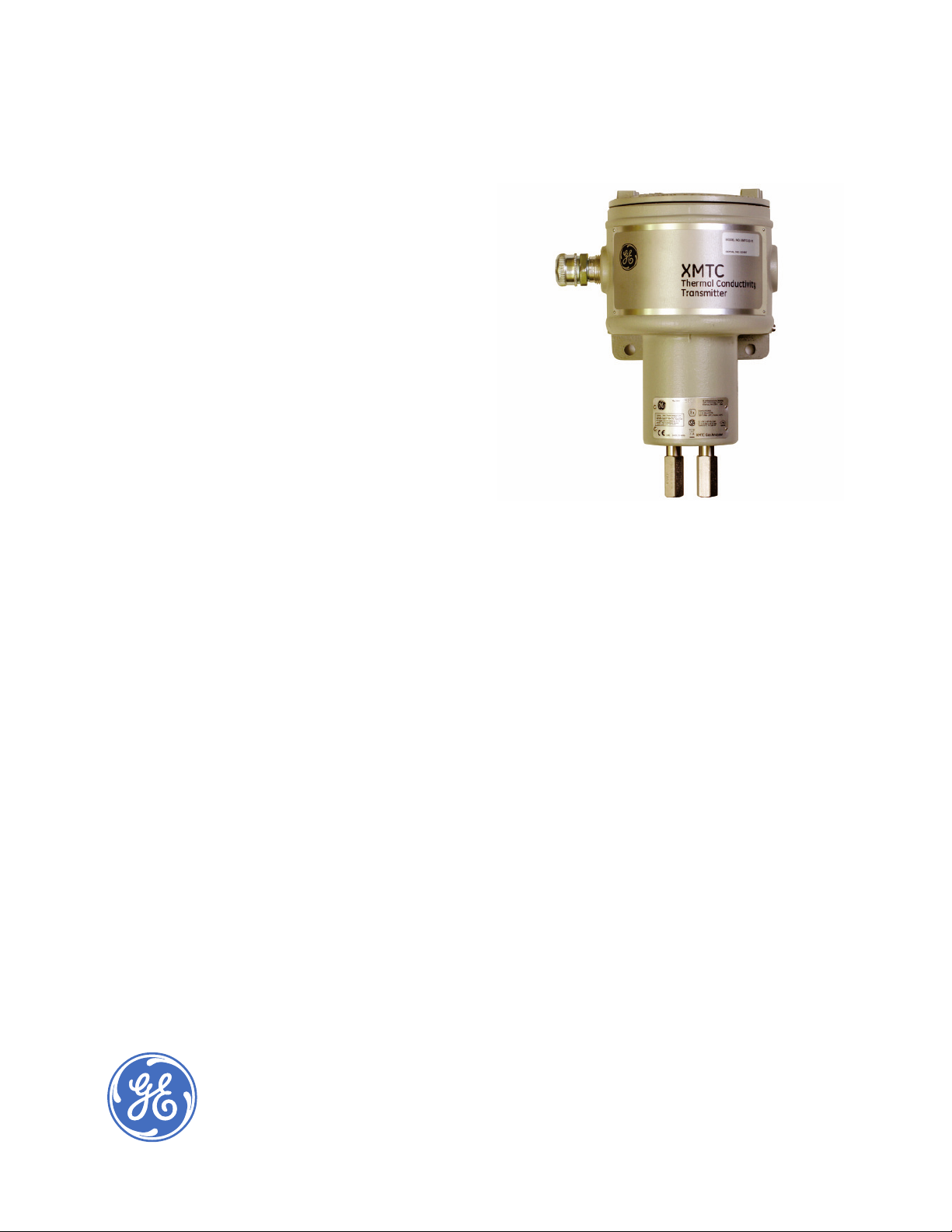
XMTC
Panametrics
Thermal Conductivity
Binary Gas Transmitter
Applications
A thermal conductivity gas transmitter for use
in the following industries and applications:
Metals Industry
H
in N2 atmosphere in metal heat-treating
2
furnaces
Electric Power Industry
H
in cooling systems for generators
2
Petroleum Industry
in hydrocarbon streams
H
2
Chemical Industry
• H
in ammonia synthesis gas
2
• H
in methanol synthesis gas
2
• H
in chlorine plants
2
Methane Industry
in methane
• CO
2
Landfi ll/Biogas Industry
in biogas
• CO
2
• CH
in biogas
4
Gas Production Industry
Purity monitoring of argon, hydrogen, nitrogen
and helium
Food Industry
CO
in fermentation processes
2
Features
• Ultra-stable glass-coated thermistors
• Single or dual gas push-button calibration
• PC interface package for digital output
• Type IP66/4X construction
• ATEX, IECEx, FM and CSA certifi ed for Zone I and
Division 1 hazardous areas
Page 2

The microprocessor-based XMTC is a compact, rugged,
online thermal conductivity transmitter that measures
the concentration of binary gas mixtures containing
hydrogen, carbon dioxide, methane or helium. The
analyzer also combines computer enhanced signal
measurement with fast-response software, real-time
error detection and digital communication via an RS232
or RS485 interface.
Theory of Operation
Two ultrastable, precision glass-coated thermistors
are used―one in contact with the sample gas and the
other in contact with the reference gas (such as air
in a sealed chamber). The thermistors are mounted
so that they are in close proximity to the stainless
steel (or Hastelloy
entire transmitter is temperature-controlled, and the
thermistors are heated to an elevated temperature in a
constant-current Wheatstone bridge. The thermistors
lose heat to the walls of the sample chamber at a rate
that is proportional to the thermal conductivity of the
gas surrounding them. Thus, each thermistor will reach
a different equilibrium temperature. The temperature
difference between the two thermistors is detected
in the Wheatstone bridge, and the resulting bridge
voltage is amplifi ed and converted to a linear 4 to 20 mA
output proportional to the concentration of one of the
constituents of the binary or pseudo binary gas mixture.
®
) walls of the sample chamber. The
Sample System
A sample system is mandatory for use with the XMTC.
The design of the sample system will depend on the
conditions of the sample gas and the requirements
of the application. In general, a sample system must
deliver a clean, representative sample to the XMTC at
a temperature, pressure and fl ow rate that are within
acceptable limits. Standard XMTC sample conditions
are: a temperature of less than 122°F (50°C) for a cell
operating temperature of 131°F (55°C) with a fl ow rate
of 0.5 SCFH (250 cc/min) at atmospheric pressure. A
higher temperature option is available.
GE offers sample systems for a wide variety of
applications. For assistance in designing your own
sample system, please consult the factory.
Relative Thermal Conductivities of
Common Gases
Air/N
2
CH
CO
2
SO
2
Ar
Cl
2
C2 - C
6
Note: Graph is relative thermal conductivity at 212°F (100°C)
Ne
4
He
H
2
Minimal Calibration and Service
The XMTC is the most stable thermal conductivity
analyzer on the market today. The rugged XMTC
measuring cell resists contamination and remains
insensitive to fl ow variations. Since the design uses
no moving parts, the transmitter can easily withstand
the shock, vibration and harsh environment found in
many industrial applications. If the transmitter requires
maintenance, its modular construction permits fast and
easy servicing. Users can fi eld-calibrate it quickly and
replace the plug-in measuring cell with a precalibrated
spare in minutes.
Gas Formula Chemical Gas Formula Chemical
Acetylene 0.90 C2H
Air 1.00 N
Argon 0.67 Ar n-Hexane 0.66 C6H
n-Butane 0.74 C4H
Carbon Dioxide 0.70 CO
Chlorine 0.34 Cl
Ethylene Alcohol 0.64 C
Ethylene 0.98 C
Ethylene Oxide 0.62 C2H4O Sulfur Dioxide 0.38 SO
Freon-11 0.37 CCI3F Water Vapor 0.77 H2O
Helium 5.53 He
2
n-Heptane 0.58 C7H
2/O2
Hydrogen 6.80 H
10
Methane 1.45 CH
2
Methyl Chloride 0.53 CH3Cl
2
Neon 1.84 Ne
2H5OH4
n-Pentane 0.70 C5H
2H4
16
14
2
4
12
2
Choosing the Reference Gas
The simple two-port version can be selected for
measurement of zero-based gas mixtures using the
sealed reference gas (air). There is a four-port version
for improved performance using a specifi c fl owing
reference gas.
Page 3

XMTC Specifi cations
Performance
Accuracy
±2% of span
Linearity
±1% of span
Repeatability
±0.5% of span
Zero Stability
±0.5% of span per week
Span Stability
±0.5% of span per week
Response Time
20 seconds for 90% step change
Measurement Ranges
• 0% to 2%
• 0% to 5%
• 0% to 10%
• 0% to 25%
• 0% to 50%
• 0% to 100%
• 50% to 100%
• 80% to 100%
• 90% to 100%
• 95% to 100%
• 98% to 100%
Measurement Gases (Typical)
• H2 in N2, air, O2 or CO
• He in N2 or air
• CO
in N2 or air
2
in air
• SO
2
• Argon in N
• H
/CO2/air for hydrogen-cooled generators
2
or air
2
Ambient Temperature Effect
±0.09% of span per °F
±0.05% of span per °C
2
*Weatherproof
**Explosion-Proof
2.76 [70]
4.13 [105]*
or
5.07 [129]**
9.54 [242.3]* or 10.48 [266.2]**
Required Sample Flow Rate
0.1 to 4.0 SCFH (10 to 2,000 cc/min);
0.5 SCFH (250 cc/min) nominal
Required Flow Rate for Optional Reference Gas
0.01 to 4.0 SCFH (5 to 2,000 cc/min);
0.5 SCFH (250 cc/min) nominal
Functional
Analog Output
4 to 20 mA isolated, 800 Ω maximum load,
fi eld-programmable
Power
24 VDC ±2 VDC, 1.2 A maximum
Temperature
• Standard: 131°F (55°C)
• Optional: 158°F (70°C)
6.10 [155]
5.71 [145]
XMTC
Transmitter
1.16 [29.5]
3.27 [83]
4.46 [113.3]
0.59 [15]
Optional Flame
Arrestors for
Explosion-Proof
Units Only
3/4” NPTF
8.66 [220]
0.39 [10]
Diameter
24 VDC/1 Amp 1
4 to 20 mA+ 3
4 to 20 mA- 4
1/4” NPTF
Note: All Dimensions = inches [mm]
6.10 [155]
Return 2
Red_RX 1
White_TX 2
Ground 3
0.47 [11.9]
Page 4

XMTC Specifi cations
Physical
Sensor Wetted Materials
• Standard:
316 stainless steel, glass and Viton
• Optional:
Hastelloy C276 and Chemraz
Dimensions
• Weatherproof unit (h x diameter):
9.53 x 5.71 in. (242 x 145 mm)
• Explosion-proof unit (h x diameter):
10.47 x 5.7 in. (266 x 145 mm)
Weight
9.5 lb (4.3 kg)
Connections
• 3/4 in NPTF (electrical conduit)
• 1/4 in NPTF (sample inlet/outlet and optional
reference inlet/outlet)
Environmental
• Weatherproof: Class I Div. 1 Groups A, B, C & D
Class II, III Div. 1 Groups E, F & G
Tamb 65°C T5 Type 4X
• Flameproof: ITS12ATEX17703X
IECEx ITS 12.0058X
II 2 G Ex d IIC T6 Gb
IP66 -20°C < Tamb < +65°C
All conduit entries 3/4” NPT
• CE: EMC 2004/108/EC and PED 97/23/EC
European Compliance
Complies with EMC Directive 2004/108/EEC
and PED 97/23/EC
CSA
Class I, Div I, Groups A, B, C and D;
Class II, Div I, Groups E, F and G;
Class III; Enclosure Type 4X
FM
®
O-rings
®
O-rings
Order and Calibration Information
XMTC Thermal Conductivity Transmitter
Measuring Cell Package
3 Weatherproof, four-port, fl owing reference gas, CPVC cell
4 Explosion-proof enclosure, four-port, fl owing reference gas,
5 Weatherproof enclosure, two-port , sealed reference gas,
6 Explosion-proof, two-port, sealed reference gas, FEP-coated
W No enclosure, two-port , sealed reference gas, FEP-coated
Y No enclosure, two-port, fl owing reference gas,
CPVC cell (spare)
CE Compliance
2 4 to 20 mA
C CE Compliant
Calibration Label for Explosion-proof Options
1 T6 Rating for Ambient Temperatures Up to 65°C
Materials
1 316 stainless steel
2 Hastelloy C276
XMTC – ___ ___ ___ ___ [Use this number to order product]
Note: For explosion-proof/fl ameproof packages, select temperature as
follows: 131°F (55°C) for EEX d IIC T6 or 149°F (65°C) for EEx d IIC T5. For
weatherproof packages, select temperature as follows: 149°F (65°C).
XMTC Calibration Specifi cations
Cell Range
2 0% to 2% 8 0% to 100%
3 0% to 5% A 90% to 100%
4 0% to 10% B 80% to 100%
6 0% to 25% C 50% to 100%
7 0% to 50% D 98% to 100%
E 95% to 100%
S Special
Calibration Gases
1 H
2 CO2 in N2 (minimum range 0% to 20% CO2)
3 CO
4 He in N
5 He in air
6 Calibration for hydrogen-cooled generators,
H
7 CH
S Other, please specify
Temperature Control Set Point
1 131°F (55°C), suitable for ambient temperatures
up to 122°F (50°C)
2 158°F (70°C), suitable for ambient temperatures
up to 149°F (65°C)
S Special
XMTC-Cal ___ ___ ___ [Use this number to order product]
Note: Binary or pseudobinary gas composition must total 100%
CPVC cell
FEP-coated aluminum cell
aluminum cell
aluminum cell (spare)
in N
2
2
in air (minimum range 0% to 20% CO2)
2
2
/CO2/air
2
in CO2 (min range 0% to 10% CH4)
4
www.gemeasurement.com
© 2016 General Electric Company. All Rights Reserved. Specifi cations are subject to change without notice. GE is a registered trademark of General Electric Company. Other company or product
names mentioned in this document may be trademarks or registered trademarks of their respective companies, which are not affi liated with GE.
920-037H
 Loading...