

Page 1
GE
Oil & Gas Flow
PanaFlow™ XMT1000
User’s Manual
910-313 Rev. A
June 2017
Page 2

Page 3

GE
Oil & Gas
PanaFlow™ XMT1000
Panametrics Liquid Flow Ultrasonic Transmitter
User’s Manual
910-313 Rev. A
June 2017
www.gemeasurement.com
©2017 General Electric Company. All rights reserved.
Technical content subject to change without notice.
Page 4

[no content intended for this page]
ii
Page 5

Contents
Product Registration . . . . . . . . . . . . . . . . . . . . . . . . . . . . . . . . . . . . . . . . . . . . . . . . . . . . . . . . . . . . . . . . . . . . . . . . . . . . . . . . . . . . . . . . vii
Services . . . . . . . . . . . . . . . . . . . . . . . . . . . . . . . . . . . . . . . . . . . . . . . . . . . . . . . . . . . . . . . . . . . . . . . . . . . . . . . . . . . . . . . . . . . . . . . . . . . . vii
Terms and Conditions . . . . . . . . . . . . . . . . . . . . . . . . . . . . . . . . . . . . . . . . . . . . . . . . . . . . . . . . . . . . . . . . . . . . . . . . . . . . . . . . . . . . . . . vii
Typographical Conventions . . . . . . . . . . . . . . . . . . . . . . . . . . . . . . . . . . . . . . . . . . . . . . . . . . . . . . . . . . . . . . . . . . . . . . . . . . . . . . . . . vii
Safety Issues . . . . . . . . . . . . . . . . . . . . . . . . . . . . . . . . . . . . . . . . . . . . . . . . . . . . . . . . . . . . . . . . . . . . . . . . . . . . . . . . . . . . . . . . . . . . . . . vii
Auxiliary Equipment. . . . . . . . . . . . . . . . . . . . . . . . . . . . . . . . . . . . . . . . . . . . . . . . . . . . . . . . . . . . . . . . . . . . . . . . . . . . . . . . . . . . . . . . viii
Environmental Compliance. . . . . . . . . . . . . . . . . . . . . . . . . . . . . . . . . . . . . . . . . . . . . . . . . . . . . . . . . . . . . . . . . . . . . . . . . . . . . . . . . . ix
Chapter 1. Installation
1.1 Introduction. . . . . . . . . . . . . . . . . . . . . . . . . . . . . . . . . . . . . . . . . . . . . . . . . . . . . . . . . . . . . . . . . . . . . . . . . . . . . . . . . . . . . . . . . . . . 1
1.2 CE Marking Compliance. . . . . . . . . . . . . . . . . . . . . . . . . . . . . . . . . . . . . . . . . . . . . . . . . . . . . . . . . . . . . . . . . . . . . . . . . . . . . . . . . 1
1.3 Unpacking the XMT1000 . . . . . . . . . . . . . . . . . . . . . . . . . . . . . . . . . . . . . . . . . . . . . . . . . . . . . . . . . . . . . . . . . . . . . . . . . . . . . . . . 2
1.4 Site and Clearance Considerations . . . . . . . . . . . . . . . . . . . . . . . . . . . . . . . . . . . . . . . . . . . . . . . . . . . . . . . . . . . . . . . . . . . . . .3
1.4.1 Access to the Meter . . . . . . . . . . . . . . . . . . . . . . . . . . . . . . . . . . . . . . . . . . . . . . . . . . . . . . . . . . . . . . . . . . . . . . . . . . . . . . . 3
1.4.2 Vibration Exposure Considerations . . . . . . . . . . . . . . . . . . . . . . . . . . . . . . . . . . . . . . . . . . . . . . . . . . . . . . . . . . . . . . . . .4
1.4.3 Sunlight Exposure . . . . . . . . . . . . . . . . . . . . . . . . . . . . . . . . . . . . . . . . . . . . . . . . . . . . . . . . . . . . . . . . . . . . . . . . . . . . . . . . . 4
1.4.4 Local Mounting. . . . . . . . . . . . . . . . . . . . . . . . . . . . . . . . . . . . . . . . . . . . . . . . . . . . . . . . . . . . . . . . . . . . . . . . . . . . . . . . . . . .5
1.4.5 Remote Mounting . . . . . . . . . . . . . . . . . . . . . . . . . . . . . . . . . . . . . . . . . . . . . . . . . . . . . . . . . . . . . . . . . . . . . . . . . . . . . . . . .6
1.4.6 Cable Lengths. . . . . . . . . . . . . . . . . . . . . . . . . . . . . . . . . . . . . . . . . . . . . . . . . . . . . . . . . . . . . . . . . . . . . . . . . . . . . . . . . . . . .6
1.4.7 Transducer Cables . . . . . . . . . . . . . . . . . . . . . . . . . . . . . . . . . . . . . . . . . . . . . . . . . . . . . . . . . . . . . . . . . . . . . . . . . . . . . . . .6
1.5 Making the Electrical Connections . . . . . . . . . . . . . . . . . . . . . . . . . . . . . . . . . . . . . . . . . . . . . . . . . . . . . . . . . . . . . . . . . . . . . . . 7
1.5.1 Wiring the Analog Outputs. . . . . . . . . . . . . . . . . . . . . . . . . . . . . . . . . . . . . . . . . . . . . . . . . . . . . . . . . . . . . . . . . . . . . . . . .9
1.5.2 Wiring the Digital Output . . . . . . . . . . . . . . . . . . . . . . . . . . . . . . . . . . . . . . . . . . . . . . . . . . . . . . . . . . . . . . . . . . . . . . . . .10
1.5.3 Wiring the Modbus/Service Port. . . . . . . . . . . . . . . . . . . . . . . . . . . . . . . . . . . . . . . . . . . . . . . . . . . . . . . . . . . . . . . . . . .11
1.5.4 Wiring the Line Power . . . . . . . . . . . . . . . . . . . . . . . . . . . . . . . . . . . . . . . . . . . . . . . . . . . . . . . . . . . . . . . . . . . . . . . . . . . .12
Chapter 2. Programming
2.1 Introduction. . . . . . . . . . . . . . . . . . . . . . . . . . . . . . . . . . . . . . . . . . . . . . . . . . . . . . . . . . . . . . . . . . . . . . . . . . . . . . . . . . . . . . . . . . .13
2.2 Using the Magnetic Keypad . . . . . . . . . . . . . . . . . . . . . . . . . . . . . . . . . . . . . . . . . . . . . . . . . . . . . . . . . . . . . . . . . . . . . . . . . . . .13
2.3 Passcodes . . . . . . . . . . . . . . . . . . . . . . . . . . . . . . . . . . . . . . . . . . . . . . . . . . . . . . . . . . . . . . . . . . . . . . . . . . . . . . . . . . . . . . . . . . . .14
2.4 Glossary of Terms . . . . . . . . . . . . . . . . . . . . . . . . . . . . . . . . . . . . . . . . . . . . . . . . . . . . . . . . . . . . . . . . . . . . . . . . . . . . . . . . . . . . .15
2.5 Menu Maps . . . . . . . . . . . . . . . . . . . . . . . . . . . . . . . . . . . . . . . . . . . . . . . . . . . . . . . . . . . . . . . . . . . . . . . . . . . . . . . . . . . . . . . . . . .16
Chapter 3. Error Codes and Troubleshooting
3.1 Error Display in the User Interface . . . . . . . . . . . . . . . . . . . . . . . . . . . . . . . . . . . . . . . . . . . . . . . . . . . . . . . . . . . . . . . . . . . . . .25
3.1.1 Error Header . . . . . . . . . . . . . . . . . . . . . . . . . . . . . . . . . . . . . . . . . . . . . . . . . . . . . . . . . . . . . . . . . . . . . . . . . . . . . . . . . . . . .25
3.1.2 Communication Error String . . . . . . . . . . . . . . . . . . . . . . . . . . . . . . . . . . . . . . . . . . . . . . . . . . . . . . . . . . . . . . . . . . . . . .25
3.1.3 Flow Error String . . . . . . . . . . . . . . . . . . . . . . . . . . . . . . . . . . . . . . . . . . . . . . . . . . . . . . . . . . . . . . . . . . . . . . . . . . . . . . . . .26
3.2 Diagnostics . . . . . . . . . . . . . . . . . . . . . . . . . . . . . . . . . . . . . . . . . . . . . . . . . . . . . . . . . . . . . . . . . . . . . . . . . . . . . . . . . . . . . . . . . . .27
3.2.1 Introduction. . . . . . . . . . . . . . . . . . . . . . . . . . . . . . . . . . . . . . . . . . . . . . . . . . . . . . . . . . . . . . . . . . . . . . . . . . . . . . . . . . . . . .27
3.2.2 Flowcell Problems . . . . . . . . . . . . . . . . . . . . . . . . . . . . . . . . . . . . . . . . . . . . . . . . . . . . . . . . . . . . . . . . . . . . . . . . . . . . . . . .27
3.2.3 Transducer/Buffer Problems . . . . . . . . . . . . . . . . . . . . . . . . . . . . . . . . . . . . . . . . . . . . . . . . . . . . . . . . . . . . . . . . . . . . . .29
PanaFlow™ XMT1000 User’s Manual iii
Page 6

Contents
Appendix A. Specifications
A.1 Operation and Performance . . . . . . . . . . . . . . . . . . . . . . . . . . . . . . . . . . . . . . . . . . . . . . . . . . . . . . . . . . . . . . . . . . . . . . . . . . .31
A.2 Electronics . . . . . . . . . . . . . . . . . . . . . . . . . . . . . . . . . . . . . . . . . . . . . . . . . . . . . . . . . . . . . . . . . . . . . . . . . . . . . . . . . . . . . . . . . . . .32
Appendix B. Modbus Communication
B.1 Modbus Protocol . . . . . . . . . . . . . . . . . . . . . . . . . . . . . . . . . . . . . . . . . . . . . . . . . . . . . . . . . . . . . . . . . . . . . . . . . . . . . . . . . . . . . .35
B.2 Modbus Register Map . . . . . . . . . . . . . . . . . . . . . . . . . . . . . . . . . . . . . . . . . . . . . . . . . . . . . . . . . . . . . . . . . . . . . . . . . . . . . . . . . 35
Appendix C. HART Communication
C.1 Wiring the XMT1000 to the HART Communicator. . . . . . . . . . . . . . . . . . . . . . . . . . . . . . . . . . . . . . . . . . . . . . . . . . . . . . . . 53
C.2 HART Write Mode Switch . . . . . . . . . . . . . . . . . . . . . . . . . . . . . . . . . . . . . . . . . . . . . . . . . . . . . . . . . . . . . . . . . . . . . . . . . . . . . .53
C.3 HART Menu Maps . . . . . . . . . . . . . . . . . . . . . . . . . . . . . . . . . . . . . . . . . . . . . . . . . . . . . . . . . . . . . . . . . . . . . . . . . . . . . . . . . . . . .54
C.3.1 HART Output Menu Map . . . . . . . . . . . . . . . . . . . . . . . . . . . . . . . . . . . . . . . . . . . . . . . . . . . . . . . . . . . . . . . . . . . . . . . . . . 54
C.3.2 HART Review Menu Map. . . . . . . . . . . . . . . . . . . . . . . . . . . . . . . . . . . . . . . . . . . . . . . . . . . . . . . . . . . . . . . . . . . . . . . . . . 55
Appendix D. Foundation Fieldbus Communication
D.1 Introduction. . . . . . . . . . . . . . . . . . . . . . . . . . . . . . . . . . . . . . . . . . . . . . . . . . . . . . . . . . . . . . . . . . . . . . . . . . . . . . . . . . . . . . . . . . .57
D.2 Installation. . . . . . . . . . . . . . . . . . . . . . . . . . . . . . . . . . . . . . . . . . . . . . . . . . . . . . . . . . . . . . . . . . . . . . . . . . . . . . . . . . . . . . . . . . . .57
D.2.1 Network Configuration . . . . . . . . . . . . . . . . . . . . . . . . . . . . . . . . . . . . . . . . . . . . . . . . . . . . . . . . . . . . . . . . . . . . . . . . . . .57
D.2.2 Polarity . . . . . . . . . . . . . . . . . . . . . . . . . . . . . . . . . . . . . . . . . . . . . . . . . . . . . . . . . . . . . . . . . . . . . . . . . . . . . . . . . . . . . . . . . . 57
D.2.3 Connection . . . . . . . . . . . . . . . . . . . . . . . . . . . . . . . . . . . . . . . . . . . . . . . . . . . . . . . . . . . . . . . . . . . . . . . . . . . . . . . . . . . . . .58
D.2.4 FISCO (Fieldbus Intrinsically Safe Concept). . . . . . . . . . . . . . . . . . . . . . . . . . . . . . . . . . . . . . . . . . . . . . . . . . . . . . . . .58
D.2.5 DD File . . . . . . . . . . . . . . . . . . . . . . . . . . . . . . . . . . . . . . . . . . . . . . . . . . . . . . . . . . . . . . . . . . . . . . . . . . . . . . . . . . . . . . . . . .60
D.2.6 Default Node Address . . . . . . . . . . . . . . . . . . . . . . . . . . . . . . . . . . . . . . . . . . . . . . . . . . . . . . . . . . . . . . . . . . . . . . . . . . . .60
D.3 Specifications . . . . . . . . . . . . . . . . . . . . . . . . . . . . . . . . . . . . . . . . . . . . . . . . . . . . . . . . . . . . . . . . . . . . . . . . . . . . . . . . . . . . . . . . .61
D.3.1 General . . . . . . . . . . . . . . . . . . . . . . . . . . . . . . . . . . . . . . . . . . . . . . . . . . . . . . . . . . . . . . . . . . . . . . . . . . . . . . . . . . . . . . . . .61
D.3.2 Physical . . . . . . . . . . . . . . . . . . . . . . . . . . . . . . . . . . . . . . . . . . . . . . . . . . . . . . . . . . . . . . . . . . . . . . . . . . . . . . . . . . . . . . . . . 61
D.3.3 Communication . . . . . . . . . . . . . . . . . . . . . . . . . . . . . . . . . . . . . . . . . . . . . . . . . . . . . . . . . . . . . . . . . . . . . . . . . . . . . . . . . 61
D.3.4 User Layer. . . . . . . . . . . . . . . . . . . . . . . . . . . . . . . . . . . . . . . . . . . . . . . . . . . . . . . . . . . . . . . . . . . . . . . . . . . . . . . . . . . . . . . 62
D.3.5 Function Blocks . . . . . . . . . . . . . . . . . . . . . . . . . . . . . . . . . . . . . . . . . . . . . . . . . . . . . . . . . . . . . . . . . . . . . . . . . . . . . . . . . .62
D.4 Resource Block. . . . . . . . . . . . . . . . . . . . . . . . . . . . . . . . . . . . . . . . . . . . . . . . . . . . . . . . . . . . . . . . . . . . . . . . . . . . . . . . . . . . . . . . 63
D.4.1 FF Revision . . . . . . . . . . . . . . . . . . . . . . . . . . . . . . . . . . . . . . . . . . . . . . . . . . . . . . . . . . . . . . . . . . . . . . . . . . . . . . . . . . . . . . 63
D.4.2 Password. . . . . . . . . . . . . . . . . . . . . . . . . . . . . . . . . . . . . . . . . . . . . . . . . . . . . . . . . . . . . . . . . . . . . . . . . . . . . . . . . . . . . . . .64
D.4.3 NAMUR NE107. . . . . . . . . . . . . . . . . . . . . . . . . . . . . . . . . . . . . . . . . . . . . . . . . . . . . . . . . . . . . . . . . . . . . . . . . . . . . . . . . . .65
D.5 XMIT Transducer Block . . . . . . . . . . . . . . . . . . . . . . . . . . . . . . . . . . . . . . . . . . . . . . . . . . . . . . . . . . . . . . . . . . . . . . . . . . . . . . . . 67
D.5.1 Units . . . . . . . . . . . . . . . . . . . . . . . . . . . . . . . . . . . . . . . . . . . . . . . . . . . . . . . . . . . . . . . . . . . . . . . . . . . . . . . . . . . . . . . . . . . .68
D.6 Composite Transducer Block. . . . . . . . . . . . . . . . . . . . . . . . . . . . . . . . . . . . . . . . . . . . . . . . . . . . . . . . . . . . . . . . . . . . . . . . . . .69
D.6.1 Clearing the Totalizer . . . . . . . . . . . . . . . . . . . . . . . . . . . . . . . . . . . . . . . . . . . . . . . . . . . . . . . . . . . . . . . . . . . . . . . . . . . .72
D.7 Channel Transducer Block . . . . . . . . . . . . . . . . . . . . . . . . . . . . . . . . . . . . . . . . . . . . . . . . . . . . . . . . . . . . . . . . . . . . . . . . . . . . .73
D.8 Analog Input Block . . . . . . . . . . . . . . . . . . . . . . . . . . . . . . . . . . . . . . . . . . . . . . . . . . . . . . . . . . . . . . . . . . . . . . . . . . . . . . . . . . . . 75
D.9 PID Block . . . . . . . . . . . . . . . . . . . . . . . . . . . . . . . . . . . . . . . . . . . . . . . . . . . . . . . . . . . . . . . . . . . . . . . . . . . . . . . . . . . . . . . . . . . . .75
iv PanaFlow™ XMT1000 User’s Manual
Page 7

Contents
D.10 Error Handling. . . . . . . . . . . . . . . . . . . . . . . . . . . . . . . . . . . . . . . . . . . . . . . . . . . . . . . . . . . . . . . . . . . . . . . . . . . . . . . . . . . . . . . . .76
D.11 Simulation Mode . . . . . . . . . . . . . . . . . . . . . . . . . . . . . . . . . . . . . . . . . . . . . . . . . . . . . . . . . . . . . . . . . . . . . . . . . . . . . . . . . . . . . .78
D.12 Fieldbus Troubleshooting Guide . . . . . . . . . . . . . . . . . . . . . . . . . . . . . . . . . . . . . . . . . . . . . . . . . . . . . . . . . . . . . . . . . . . . . . . .79
D.13 DPI620 FF Modular Communicator . . . . . . . . . . . . . . . . . . . . . . . . . . . . . . . . . . . . . . . . . . . . . . . . . . . . . . . . . . . . . . . . . . . . .80
Index. . . . . . . . . . . . . . . . . . . . . . . . . . . . . . . . . . . . . . . . . . . . . . . . . . . . . . . . . . . . . . . . . . . . . . . . . . . . . . . . . . . . . . . . . . . . . . . . . . . . . . .81
PanaFlow™ XMT1000 User’s Manual v
Page 8

Contents
[no content intended for this page]
vi PanaFlow™ XMT1000 User’s Manual
Page 9

Preface
Product Registration
Thank you for purchasing a model PanaFlow™ XMT1000 from GE. Please register your product at
www.gemeasurement.com/productregistration
product information and special promotions.
for product support such as the latest software/firmware upgrades,
Services
GE provides customers with an experienced staff of customer support personnel ready to respond to technical inquiries,
as well as other remote and on-site support needs. To complement our broad portfolio of industry-leading solutions, we
offer several types of flexible and scalable support services including: Training, Product Repairs, Service Agreements
and more. Please visit www.gemeasurement.com/services
for more details.
Terms and Conditions
GE’s sales Terms and Conditions for your recent purchase of a GE product, including the applicable product Warranty,
can be found on our website at the following link: www.gemeasurement.com/sales-terms-and-conditions
Typographical Conventions
Note: These paragraphs provide information that provides a deeper understanding of the situation, but is not
essential to the proper completion of the instructions.
IMPORTANT: These paragraphs provide information that emphasizes instructions that are essential to proper setup of
the equipment. Failure to follow these instructions carefully may cause unreliable performance.
CAUTION! This symbol indicates a risk of potential minor personal injury and/or severe damage to
the equipment, unless these instructions are followed carefully.
WARNING! This symbol indicates a risk of potential serious personal injury, unless these instructions
are followed carefully.
Safety Issues
WARNING! It is the responsibility of the user to make sure all local, county, state and national codes,
regulations, rules and laws related to safety and safe operating conditions are met for each
installation.
Attention European Customers! To meet CE Marking requirements for all units intended for use in
the EU, all electrical cables must be installed as described in this manual.
PanaFlow™ XMT1000 User’s Manual vii
Page 10

Preface
Auxiliary Equipment
Local Safety Standards
The user must make sure that he operates all auxiliary equipment in accordance with local codes, standards,
regulations, or laws applicable to safety.
Working Area
WARNING! Auxiliary equipment may have both manual and automatic modes of operation. As
equipment can move suddenly and without warning, do not enter the work cell of this equipment
during automatic operation, and do not enter the work envelope of this equipment during manual
operation. If you do, serious injury can result.
WARNING! Make sure that power to the auxiliary equipment is turned OFF and locked out before
you perform maintenance procedures on this equipment.
Qualification of Personnel
Make sure that all personnel have manufacturer-approved training applicable to the auxiliary equipment.
Personal Safety Equipment
Make sure that operators and maintenance personnel have all safety equipment applicable to the auxiliary equipment.
Examples include safety glasses, protective headgear, safety shoes, etc.
Unauthorized Operation
Make sure that unauthorized personnel cannot gain access to the operation of the equipment.
viii PanaFlow™ XMT1000 User’s Manual
Page 11

Environmental Compliance
RoHS
The PanaFlow™ XMT1000 fully complies with RoHS regulations (Directive 2011/65/EU).
Waste Electrical and Electronic Equipment (WEEE) Directive
GE is an active participant in Europe’s Waste Electrical and Electronic Equipment (WEEE) take-back initiative
(Directive 2012/19/EU).
The equipment that you bought has required the extraction and use of natural resources for its production. It may
contain hazardous substances that could impact health and the environment.
Preface
In order to avoid the dissemination of those substances in our environment and to diminish the pressure on the natural
resources, we encourage you to use the appropriate take-back systems. Those systems will reuse or recycle most of the
materials of your end life equipment in a sound way.
The crossed-out wheeled bin symbol invites you to use those systems.
If you need more information on the collection, reuse and recycling systems, please contact your local or regional
waste administration.
Please visit http://www.gemeasurement.com/environmental-health-safety-ehs
information about this initiative.
for take-back instructions and more
PanaFlow™ XMT1000 User’s Manual ix
Page 12

Preface
[no content intended for this page]
x PanaFlow™ XMT1000 User’s Manual
Page 13
Chapter 1. Installation
Chapter 1. Installation
1.1 Introduction
To ensure safe and reliable operation of the XMT1000, it must be installed in accordance with the established
guidelines. Those guidelines, explained in detail in this chapter, include the following topics:
• Unpacking the XMT1000
• Selecting the location for the XMT1000 (local or remote)
• Installing the XMT1000 at the selected location
• Wiring the XMT1000
WARNING! The XMT1000 flow transmitter can measure the flow rate of many fluids, some of which
are potentially hazardous. The importance of proper safety practices cannot be overemphasized.
Be sure to follow all applicable local safety codes and regulations for installing electrical equipment
and working with hazardous fluids or flow conditions. Consult company safety personnel or local
safety authorities to verify the safety of any procedure or practice.
Attention European Customers! To meet CE Marking requirements, all cables must be installed as
described in “CE Marking Compliance” on page 1.
1.2 CE Marking Compliance
For CE Marking compliance or installation in high noise areas, the XMT1000 flow transmitter must be wired in
accordance with the instructions in this section.
IMPORTANT: CE Marking compliance is required for all units intended for use in EU countries.
The XMT1000 must be wired with the recommended cable, and all connections must be properly shielded and
grounded. Grounding of the chassis must be within 10 ft (3 m) of the transmitter. Refer to Tab le 1 below for the specific
requirements.
Table 1: Wiring Requirements
Connection Cable Type Ground Termination
Transducer Armored RG-62 a/U or equivalent Grounded using a cable gland.
Input/Output Armored 22 AWG shielded with armored material added to
outside of jacket
Power Armored 14 AWG 2 conductor Grounded using a cable gland.
Note: If the XMT1000 is wired as described above, the unit will comply with the EMC and LVD Directives.
Grounded using a cable gland.
PanaFlow™ XMT1000 User’s Manual 1
Page 14

Chapter 1. Installation
Model & Serial Number (Boston) Model & Serial Number (Shannon)
Certification (US/CAN, IECEx/ATEX)
[FISCO]
Certification (US/CAN, IECEx/ATEX)
[Standard]
1.3 Unpacking the XMT1000
Before removing the XMT1000 from its box, please inspect both the box and the instrument carefully. Each instrument
manufactured by GE is warranted to be free from defects in material and workmanship. Before discarding any of the
packing materials, account for all components and documentation listed on the packing slip. The discarding of an
important item along with the packing materials is all too common. If anything is missing or damaged, contact GE
Customer Care immediately for assistance.
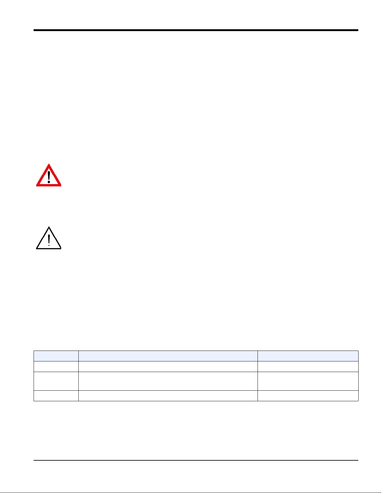
The XMT1000 is supplied with both a serial number label and a certification label for identification of the instrument
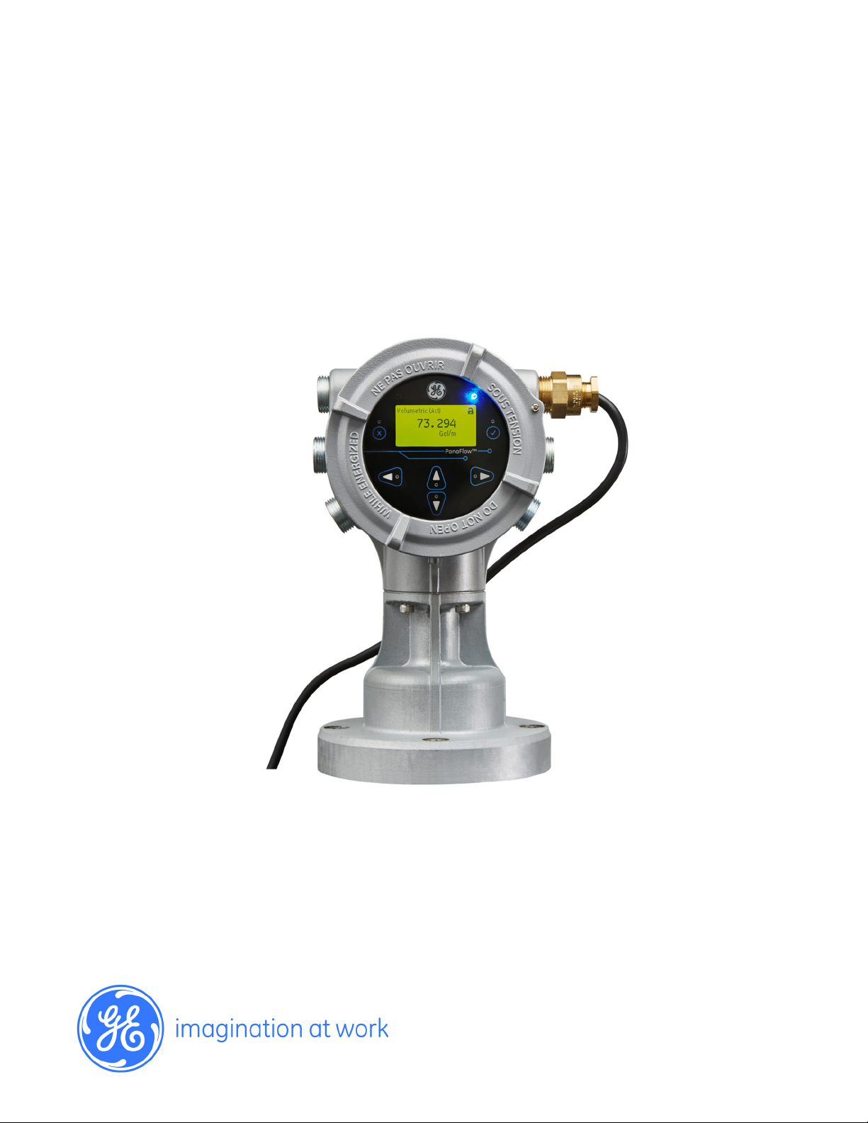
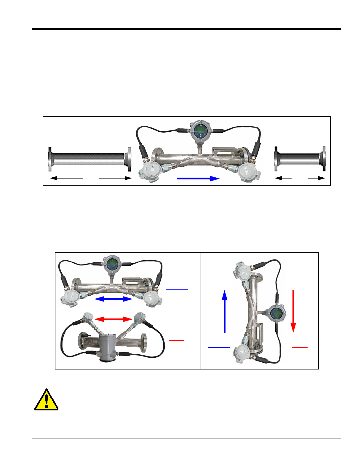
(see Figure 1 below and Figure 2 on page 3). The system can be mounted either on an existing meter body (local
mounting) or at another location via a connecting cable (remote mounting).
Figure 1: Typical XMT1000 Labels (Aluminum Enclosure)
2 PanaFlow™ XMT1000 User’s Manual
Page 15
1.3 Unpacking the XMT1000 (cont.)
Model & Serial Number (Boston) Model & Serial Number (Shannon)
Certification (US/CAN, IECEx/ATEX)
[FISCO]
Certification (US/CAN, IECEx/ATEX)
[Standard]
Chapter 1. Installation
Figure 2: Typical XMT1000 Labels (Stainless Steel Enclosure)
1.4 Site and Clearance Considerations
1.4.1 Access to the Meter
Because the relative location of the flowcell and the XMT1000 transmitter is important, use the guidelines in this
section to plan the XMT1000 installation.
For flowcell clearance recommendations, consult the manual for your specific flow meter system or contact GE for
assistance. Access to the XMT1000 flow transmitter should be uninhibited, as defined by the minimum clearance
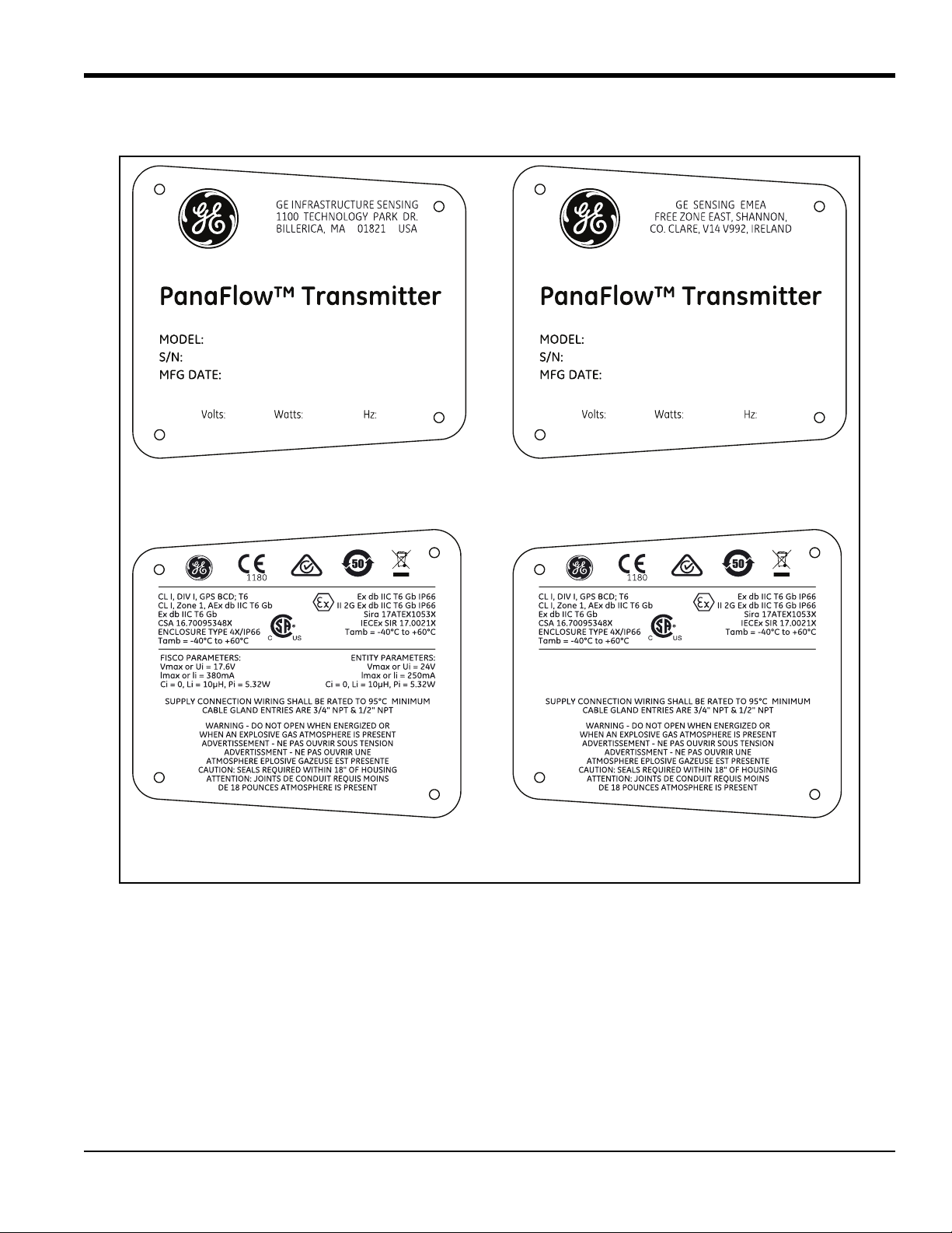
distances around the enclosure specified in Figure 3 on page 4.
PanaFlow™ XMT1000 User’s Manual 3
Page 16
Chapter 1. Installation
1000 SERIES ELECTRONICS
12 in. (300 mm) CLEARANCE
MINIMUM RECOMMENDED
FOR CABLE ENTRY
12 in. (300 mm) CLEARANCE
MINIMUM RECOMMENDED
FOR CABLE ENTRY
12 in. (300 mm) CLEARANCE
MINIMUM RECOMMENDED
FOR SERVICE ACCESS
12 in. (300 mm) CLEARANCE
MINIMUM RECOMMENDED
FOR SERVICE ACCESS
12 in. (300 mm) CLEARANCE
MINIMUM RECOMMENDED
FOR CABLE ENTRY
CUSTOMER SUPPLIED 2” PIPE
1000 SERIES
REMOTE MOUNT KIT
1.4.1 Access to the Meter (cont.)
Figure 3: XMT1000 Enclosure Clearances (ref. dwg. 712-2164)
1.4.2 Vibration Exposure Considerations
Whenever possible, install the XMT1000 flow transmitter in a location isolated from vibrations. Avoid installing it near
equipment that generates low-frequency, high-energy random vibrations.
1.4.3 Sunlight Exposure
The installer should consider and limit exposure of the XMT1000 flow transmitter to direct sunlight. Sunshades should
be utilized in extreme environments.
4 PanaFlow™ XMT1000 User’s Manual
Page 17
Chapter 1. Installation
Flow Direction
10D 5D
BAD
Vertical
GOOD
Flow Direction
Flow Direction
Flowcell
Flow Direction
GOOD
BAD
Horizontal
Flowcell
1.4.4 Local Mounting
The XMT1000 accuracy is affected by the flowcell location in the process piping and on the orientation of the
transducers. Thus, in addition to accessibility for maintenance, adhere to the following installation guidelines:
• Locate the flowcell so that there are at least 10 pipe diameters of straight, undisturbed flow upstream and
5 pipe diameters of straight, undisturbed flow downstream from the measurement point (see Figure 4 below).
Undisturbed flow means avoiding sources of turbulence in the fluid (e.g., valves, flanges, expansions, elbows,
etc.), avoiding swirl, and avoiding cavitation.
Figure 4: Minimum Straight Run Pipe Requirements
• Locate the transducers on a common axial plane along the pipe. Also, locate them on the side of the pipe
instead of on the top or the bottom, because the top of the pipe tends to accumulate gas and the bottom tends to
accumulate sediment. Either condition will cause unwanted attenuation of the ultrasonic signals. There is no
similar restriction with vertical pipes, as long as the fluid flow is upward to prevent free falling of the fluid or a
less than full pipe (see Figure 5 below).
Figure 5: Good and Bad Flowcell/Transducer Orientations
CAUTION! Do not place thermal insulation on or around the transducers, the junction boxes, or the
meter electronics. The transducer and junction box act as a heat sink that protects the transducer
PanaFlow™ XMT1000 User’s Manual 5
from high and low temperatures.
Page 18

Chapter 1. Installation
1.4.5 Remote Mounting
The standard XMT1000 enclosure is a powder-coated, aluminum, IP67 explosion-proof enclosure. Typically, the
enclosure is mounted as close as possible to the transducers. When choosing a site for a remote-mount installation,
which is recommended for process temperatures exceeding 150°C, make sure the location permits easy access to the
enclosure for programming, maintenance and service.
Attention European Customers! For compliance with the European Union’s Low Voltage Directive,
this unit requires an external power disconnect device such as a switch or circuit breaker. The
disconnect device must be marked as such, clearly visible, directly accessible, and located within
1.8 m (6 ft) of the unit.
1.4.6 Cable Lengths
Locate the XMT1000 as close as possible to the transducers. The maximum distance from the transducers for remote
mounting of the XMT1000 is 1000 ft (300 m) using RG-62 coaxial cable or equivalent. If longer distances are required,
consult the factory for assistance.
1.4.7 Transducer Cables
When installing the transducer cables, always observe established standard practices for the installation of electrical
cables. Do not route transducer cables alongside high amperage AC power lines or any other cables that could cause
electrical interference. Also, protect the transducer cables and connections from the weather and corrosive
atmospheres, and be sure to follow the manufacturer's installation guidelines if cable glands are provided.
6 PanaFlow™ XMT1000 User’s Manual
Page 19
Chapter 1. Installation
1.5 Making the Electrical Connections
This section contains instructions for making all the necessary electrical connections for the XMT1000 flow
transmitter. Refer to Figure 6 on page 8 for a complete wiring diagram.
Note: Both flying lead and MCX transducer connectors are shown in the figure for completeness. Only the type of
connector appropriate for each meter ordered will be installed on the PCB.
WARNING! Always disconnect the line power from the XMT1000 before removing either the front
cover or the rear cover. This is especially important in a hazardous environment.
Attention European Customers! To meet CE Marking requirements, all cables must be installed as
described in “CE Marking Compliance” on page 1.
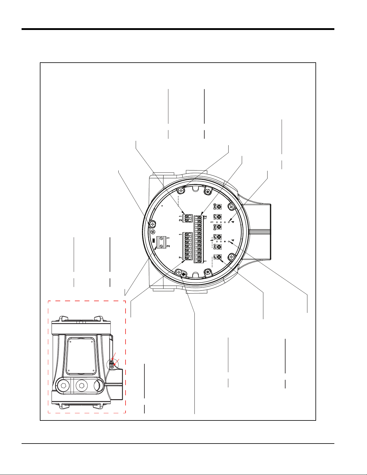
Prepare the XMT1000 for wiring by completing the following steps:
• To access the wiring terminals, complete the following steps:
1. Disconnect any previously wired power line from the unit.
2. Loosen the set screw on the wiring cover.
3. Place a rod or long screwdriver across the cover in the slots provided, and rotate the cover counterclockwise
until it comes free from the enclosure.
4. Install any required cable glands in the appropriate conduit holes on the opposite side of the enclosure.
5. Note the labels inside the rear cover to assist in wiring the power and option connections.
• Wiring any option set requires completion of the following general steps:
1. Disconnect the main power from the unit and remove the wiring cover.
2. Install a cable gland in the chosen conduit hole on the side of the electronics enclosure and feed a standard
26-12 AWG twisted-pair cable through this conduit hole.
3. Locate the Standard I/O or Analog I/O options terminal block and wire the option as indicated on the label
inside the wiring cover. Secure the cable gland.
4. If wiring of the unit has been completed, reinstall the wiring cover on the enclosure and tighten the set screw.
WARNING! Proper grounding of the XMT1000 enclosure via the external grounding screw on the
enclosure (see Figure 6 on page 8) is required to prevent the possibility of electric shock. All ground
screws should be hand tightened only, to a maximum allowable torque of 2.5 N-m (22 in-lb).
For specific instructions on wiring a particular output configuration, proceed to the appropriate sub-section.
PanaFlow™ XMT1000 User’s Manual 7
Page 20
Chapter 1. Installation
CH2 FLYING LEAD TERMINAL BLOCK (TB6)
ACCEPTS 26-12 AWG WIRE
PIN DESCRIPTION
1 CH 2 DOWNSTREAM SIG (+)
2 CH 2 DOWNSTREAM RTN (-)
3 CH 2 UPSTREAM RTN (-)
4 CH 2 UPSTREAM SIG (+)
CH1 FLYING LEAD TERMINAL BLOCK (TB5)
ACCEPTS 26-12 AWG WIRE
PIN DESCRIPTION
1 CH 1 DOWNSTREAM SIG (+)
2 CH 1 DOWNSTREAM RTN (-)
3 CH 1 UPSTREAM RTN (-)
4 CH 1 UPSTREAM SIG (+)
MCX TERMINAL CONNECTORS
ACCEPTS 50 RIGHT ANGLE MCX PLUG
PIN DESCRIPTION
UP1 CH 1 UPSTREAM
DN1 CH 1 DOWNSTREAM
UP2 CH 2 UPSTREAM
DN2 CH 2 DOWNSTREAM
UP3 CH 3 UPSTREAM
DN3 CH 3 DOWNSTREAM
*ENCLOSURE MAIN CUSTOMER GROUND
STANDARD I/O TERMINAL BLOCK (TB3)
ACCEPTS 26-12 AWG WIRE
PIN DESCRIPTION
1 RS485 MODBUS (+)
2 RS485 MODBUS (-)
3 RS485 COMMON
4 FREQUENCY/TOTALIZER/CAL (+)
5 FREQUENCY/TOTALIZER/CAL (-)
6 ANALOG 4-20MA OUT (+)
7 ANALOG 4-20MA RTN (-)
ADDITIONAL CUSTOMER GROUND, 3X
PCB GROUND
DIGITAL COMMUNICATION
TERMINAL BLOCK (TB1)
NONE, [OR]
+$577(50,1$/%/2&.
ACCEPTS 26-12 AWG WIRE
PIN DESCRIPTION
1 HART (+)
2 HART (-)
[OR]
)281'$7,21),(/'%86
ACCEPTS 26-12 AWG WIRE
PIN DESCRIPTION
1 FIELDBUS NET (+)
2 FIELDBUS NET (-)
ANALOG I/O TERMINAL BLOCK (TB2)
ACCEPTS 26-12 AWG WIRE
FOR FUTURE USE
LINE POWER TERMINAL BLOCK (TB4)
ACCEPTS 20-10 AWG WIRE
$&
PIN DESCRIPTION
1 (L1) LINE
2 (L2/N) NEUTRAL
* CONNECT GROUND TO CHASSIS
[OR]
'&
PIN DESCRIPTION
1 +
2 -
* CONNECT GROUND TO CHASSIS
CASTED GROUND SYMBOL
EXTERIOR GROUND SCREW
[TB1]
[TB2]
[TB3]
[TB4]
[TB5]
[TB6]
1.5 Making the Electrical Connections (cont.)
Figure 6: XMT1000 Terminal Board Wiring Diagram (ref. dwg. 702-2040)
8 PanaFlow™ XMT1000 User’s Manual
Page 21

Chapter 1. Installation
1.5.1 Wiring the Analog Outputs
The standard configuration of the XMT1000 flow transmitter includes one isolated 4-20 mA analog output.
Connections to this output may be made with standard twisted-pair wiring, but the current loop impedance for this
circuit must not exceed 600 ohms. Two additional analog outputs are available as an option.
To wire the analog outputs, complete the following steps:
1. Disconnect the main power to the unit and remove the wiring cover.
2. Install the required cable gland in the chosen conduit hole on the side of the electronics enclosure.
3. Refer to Figure 6 on page 8 for the location of the terminal block and wire the analog output as shown. Secure
the cable gland.
Attention European Customers! To meet CE Marking requirements, all cables must be installed as
described in “CE Marking Compliance” on page 1.
IMPORTANT: Analog output A is an active signal. Do not supply power to this circuit, as the circuit is powered by the
flow meter.
4. If wiring of the unit has been completed, reinstall the wiring cover on the enclosure and tighten the set screw.
WARNING! Make sure all covers, with their o-ring seals, are installed and the set screws tightened
before applying power in a hazardous environment.
Note: Prior to use, the analog output must be set up and calibrated. Proceed to the next section to continue the initial
wiring of the unit.
Note: See Appendix A, Specifications, for the load and voltage requirements.
PanaFlow™ XMT1000 User’s Manual 9
Page 22

Chapter 1. Installation
1.5.2 Wiring the Digital Output
The standard XMT1000 flow transmitter configuration includes one isolated digital output, which can be used as a
totalizer (pulse) output, a frequency output, or a calibration port. Wiring this output requires completion of the
following general steps:
1. Disconnect the main power to the unit and remove the wiring cover.
2. Install the required cable gland in the chosen conduit hole on the side of the electronics enclosure.
3. Refer to Figure 6 on page 8 for the location of the terminal block and wire the digital output as shown. Secure
the cable gland.
Attention European Customers! To meet CE Marking requirements, all cables must be installed as
described in “CE Marking Compliance” on page 1
4. If wiring of the unit has been completed, reinstall the wiring cover on the enclosure and tighten the set screw.
1.5.2a Wiring as a Totalizer (Pulse) Output
Wire this option in accordance with the connections shown on the label in the rear cover (see Figure 6 on page 8).
Refer to Appendix A, Specifications for the load and voltage requirements.
1.5.2b Wiring as a Frequency Output
Wire this option in accordance with the connections shown on the label in the rear cover (see Figure 6 on page 8).
Refer to Appendix A, Specifications for the load and voltage requirements.
1.5.2c Wiring as a Calibration Port
The XMT1000 flow transmitter is equipped with a calibration port specifically designed for calibrating the XMT1000.
It is wired for a frequency output. To wire to this port, refer to Figure 6 on page 8 and complete the following steps:
Note: Performing a calibration of the meter requires entering an Admin-level password.
1. Disconnect the main power to the unit and remove the rear cover.
2. Install the required cable gland in the chosen conduit hole on the side of the electronics enclosure.
3. Feed one end of the cable through the conduit hole, wire it to the terminal block.
4. If wiring of the unit has been completed, reinstall the wiring cover on the enclosure and tighten the set screw.
WARNING! Make sure all covers, with their o-ring seals, are installed and the set screws tightened
before applying power in a hazardous environment.
10 PanaFlow™ XMT1000 User’s Manual
Page 23

Chapter 1. Installation
1.5.3 Wiring the Modbus/Service Port
The XMT1000 flow transmitter is equipped with a Modbus communication port for either a connection to Vitality (PC
software) or to a separate control system. The port is an RS485 interface.
IMPORTANT: The maximum cable length for an RS485 connection is 4000 ft (1200 m).
To wire to this RS485 serial port, refer to Figure 6 on page 8 and complete the following steps:
1. Disconnect the main power to the unit and remove the rear cover.
2. Install the required cable gland in the chosen conduit hole on the side of the electronics enclosure.
3. Feed one end of the cable through the conduit hole, and wire it to the terminal block.
4. If wiring of the unit has been completed, reinstall the wiring cover on the enclosure and tighten the set screw.
Note: Prior to use, the serial port must be programmed.
WARNING! Make sure all covers, with their o-ring seals, are installed and the set screws tightened
before applying power in a hazardous environment.
PanaFlow™ XMT1000 User’s Manual 11
Page 24
Chapter 1. Installation
1.5.4 Wiring the Line Power
The XMT1000 may be ordered for operation with power inputs of either 100-240 VAC or 12-28 VDC. The label on the
side of the enclosure lists the meter’s required line voltage and power rating. Be sure to connect the meter to the
specified line voltage only.
Attention European Customers! For compliance with the European Union’s Low Voltage Directive,
this unit requires an external power disconnect device such as a switch or circuit breaker. The
disconnect device must be marked as such, clearly visible, directly accessible, and located within
1.8 m (6 ft) of the unit.
WARNING! Improper connection of the line power leads or connecting the meter to the incorrect
line voltage may damage the unit. It may also result in hazardous voltages at the flowcell and
associated piping as well as within the electronics enclosure.
Refer to Figure 6 on page 8 to locate the terminal blocks and connect the line power as follows:
1. Prepare the line power leads by trimming the line and neutral AC power leads (or the positive and negative DC
power leads) to a length 0.5 in. (1 cm) shorter than the ground lead. This ensures that the ground lead is the last
to detach if the power cable is forcibly disconnected from the meter.
2. Install a suitable cable gland in the conduit hole. If possible, avoid using the other conduit holes for this
purpose, to minimize any interference in the circuitry from the AC power line.
Attention European Customers! To meet CE Marking requirements, all cables must be installed as
described in “CE Marking Compliance” on page 1.
3. Route the cable through the conduit hole and connect the line power leads to the power terminal, using the pin
number assignments shown in Figure 6 on page 8.
IMPORTANT: The ground wire must be connected to the system chassis.
4. Leaving a bit of slack, secure the power line with the cable clamp.
5. If wiring of the unit has been completed, reinstall the wiring cover on the enclosure and tighten the set screw.
WARNING! Make sure all covers, with their o-ring seals, are installed and the set screws tightened
before applying power in a hazardous environment.
CAUTION! The transducers must be properly wired before applying power to the meter.
12 PanaFlow™ XMT1000 User’s Manual
Page 25
Chapter 2. Programming
Chapter 2. Programming
2.1 Introduction
This chapter provides instructions for programming the various features of the XMT1000 flow transmitter. Before the
XMT1000 can begin taking measurements, settings for the User Preferences and Inputs/Outputs must be entered and
tested. To program your XMT1000, see the next section for programming instructions and refer to “Menu Maps” on
page 16 to configure the desired features.
Note: For help with the programming of any system parameters which may be unclear, refer to “Glossary of Terms”
on page 15 for a brief description of the standard flow meter terminology used in this manual.
2.2 Using the Magnetic Keypad
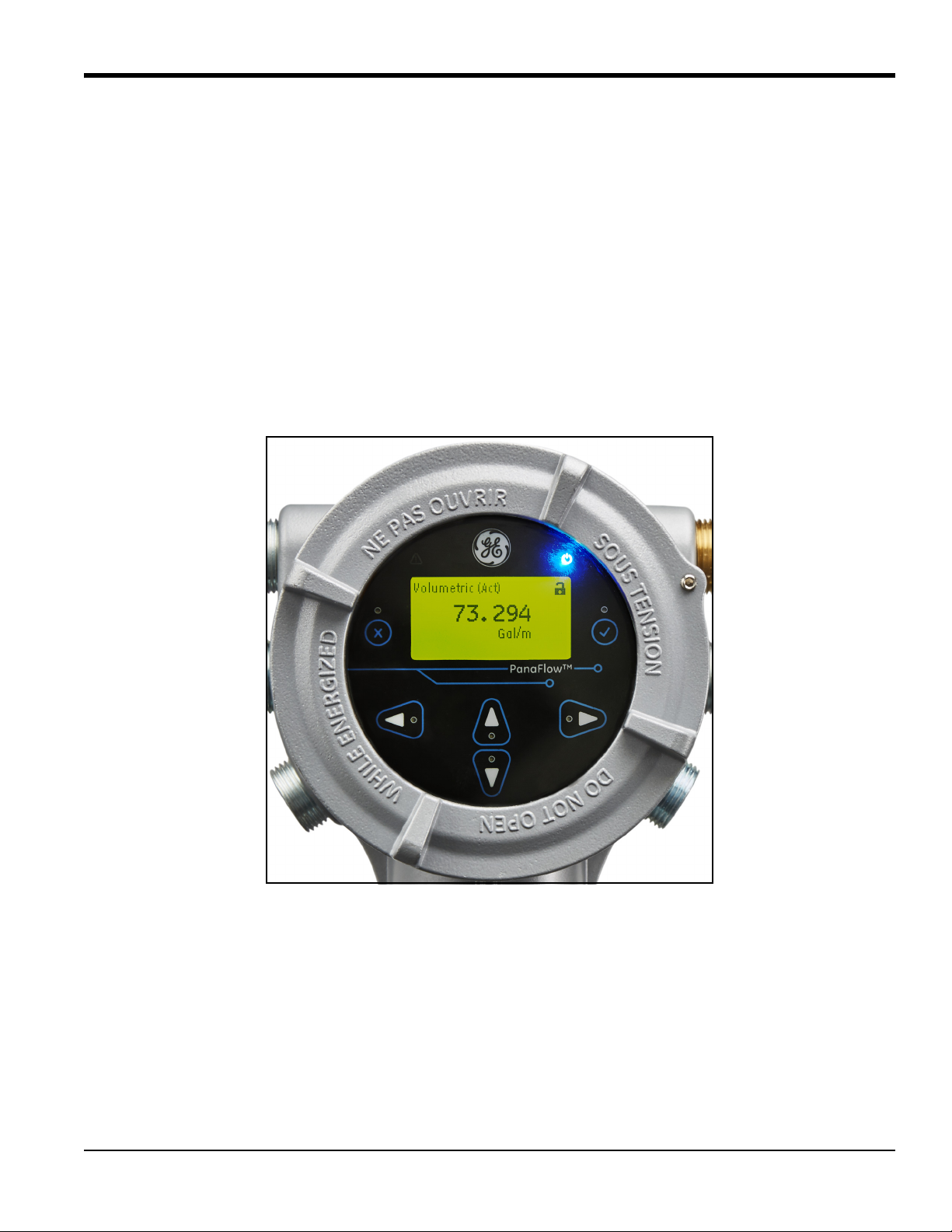
The display window on the XMT1000 includes the components shown in Figure 7 below.
Figure 7: The Display and Keypad
IMPORTANT: The XMT1000 magnetic keypad enables programming of the instrument through the glass faceplate
without removing the cover. Thus, all programming procedures may be performed while the unit is
installed in a hazardous area.
PanaFlow™ XMT1000 User’s Manual 13
Page 26

Chapter 2. Programming
INITIALIZE . . .
XMT 1000
Velocity
m/s
9.3
2.2 Using the Magnetic Keypad (cont.)
Above the display, the blue light is for power indication and the red light is for system health indication. Once system
power is applied, the blue light stays on until power is lost. The red light blinks when the system is in error. When the
red light is off - the system is operating without error.
The six keys on the magnetic keypad are used to program the XMT1000:
• [√] - confirms the choice of a specific option and data entry within that option
• [] - enables users to exit from a specific option without entering unconfirmed data
• [] and [] - enable users to highlight a specific window in the display option or to scroll through a list of
options (parameters, letters, and numbers, 0-9 as well as the negative sign and decimal point) in a menu
• [] and [] - enable users to scroll to a specific option, among choices in an option, or to a character in a text
entry.
When the XMT1000 is powered up, the initial screen display appears, followed by meter boot up, then by a display of
measurement parameters.
As a guide to help follow the programming instructions in this chapter, the XMT1000 menu maps have been
reproduced in Figure 8 on page 17 through Figure 15 on page 24.
IMPORTANT: If the keypad has not been pressed for 10 minutes, the XMT1000 exits the Keypad Program and returns
to displaying measurements. Because changes can only be retained after the user confirms them, the
meter discards any unconfirmed configuration changes.
2.3 Passcodes
The default passcodes for the XMT1000 flow transmitter are:
• Default Operator Password = 111111
• Default Admin Password = 111111
IMPORTANT: The default Admin password must be changed before the meter is placed into service, and the new
Admin password must be properly secured. Unauthorized access to the Admin menus may result in
programming changes that have a negative impact on the performance and operation of the meter.
14 PanaFlow™ XMT1000 User’s Manual
Page 27

Chapter 2. Programming
2.4 Glossary of Terms
Backlight: The LCD display backlight has three user-adjustable parameters. The brightness, the contrast, and the
•
length of inactivity which triggers automatic shutdown can be individually set within available limits.
• Error Handling: The manner in which various XMT1000 outputs respond to automatically generated system errors
can be set by the user by selecting the options from a drop-down list.
• Frequency Output: In frequency mode, the digital output generates a pulse with a frequency that is proportional to
the magnitude of the measured flow parameter (e.g., 10 Hz = 1ft
3
/hr).
• HART: HART is a serial communication protocol used for industrial automation. Its main advantage is that it can
communicate over 4-20 mA analog instrumentation current loops over the pair of wires used by the analog only
host system.
• K-Factor: To calibrate the XMT1000 against a reference value, the raw flow velocity readings may need to have a
correction factor applied. This K-Factor can be a single constant or a table of K-Factor vs. Velocity values.
• Loop Powered: Loop powered analog devices use the power provided by the meter itself rather than by an external
power supply. This results in a simple 2-wire connection between the meter and the external device.
• Mass Flow: Mass flow is the mass of fluid passing the measurement point in a given period of time. This value is
calculated by the meter from the measured flow velocity and the programmed pipe and fluid parameters.
• Modbus: Modbus is a serial communication protocol developed by Modicon
controllers. It is a method used for transmitting information over serial lines between electronic devices.
®
for use with its programmable logic
• Pulse Output: In pulse/totalizer mode, the digital output generates a pulse with a width corresponding to one unit
of the measured flow parameter (e.g., 1 pulse = 1 ft
3
).
• Reynolds Correction: When turned on, a factor based on the kinematic viscosity and the flow rate of the fluid is
applied to all measurements. Reynolds correction should be On for most applications.
• Serial Port Settings: When the XMT1000 serial port is connected to an external serial device, communication
between the two devices only occur if the serial port settings of the two devices match. These settings include:
baud rate, data bits, stop bits, and parity.
• Special Transducer: If your transducer has no number engraved on the body, select SPECIAL in the Transducer
Number menu.
• Tw: The TW parameter is the time the transducer signal spends traveling through the transducer body and the
transducer cable. This value must be subtracted from the total signal transit time to calculate the actual signal
transit time only through the fluid.
• Totalizer: The totalizer accumulates a running total of the amount of fluid which passes the measurement point
between specified start and stop times.
• Tracking Window: The tracking window is used to detect the receive signal when you are unsure of the fluid
sound speed. For the XMT1000 flow transmitter, the Tracking Window is always ON.
• Zero Cutoff: When the measured flow rate is below the zero cutoff value, the display is forced to 0.00. This is to
avoid rapid fluctuations in the reading whenever the flow rate is close to zero.
PanaFlow™ XMT1000 User’s Manual 15
Page 28

Chapter 2. Programming
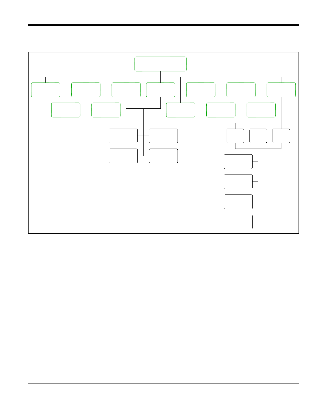
2.5 Menu Maps
Use the menu maps in this section to program the desired XMT1000 features.
• "Measurement Display Menu Map (Rev. 10)" on page 17
• "Main Menu Map (Rev. 10)" on page 18
• "SYSTEM Menu Map (Rev. 10)" on page 19
• "MAIN Board I/O Menu Map (Rev. 10)" on page 20
• "OPTION Boards Menu Map (Rev. 10)" on page 21
• "SENSOR SETUP Menu Map (Rev. 10)" on page 22
• "CALIBRATION Menu Map (Rev. 10)" on page 23
• "ADVANCED Menu Map (Rev. 10)" on page 24
In addition, the following menu maps are available in Appendix C:
• “HART Output Menu Map” on page 54
• “HART Review Menu Map” on page 55
IMPORTANT: Not all users will have access to all of the above menus. Some menus are restricted to only those users
with the proper passcodes.
16 PanaFlow™ XMT1000 User’s Manual
Page 29
2.5 Menu Maps (cont.)
Velocity
Volumetric
Actual
Volumetric
Standard
Mass
Soundspeed
Diagnostics
Total
Batch
Total
Inventory
Forward
Net
Time
Reverse
Ch 1 Ch 2 Ch 3
Values
Flow
Quality
Signal
Process
Signal
Status
System
Measurement Menu
Press to Enter the Display
9
K-Factor
Reynolds
Number
Reylnolds
K-Factor
Temperature
On Board
Chapter 2. Programming
Figure 8: Measurement Display Menu Map (Rev. 10)
PanaFlow™ XMT1000 User’s Manual 17
Page 30

Chapter 2. Programming
PASSWORDS
When the keypad is locked, press
[ ], [ ], [ ] to open the password
screen. Enter an Admin password
to unlock the keypad.
(Operator Password)
9
88
Operator Password (default password = 111111)
Admin Password (default password = 111111)
Contact the factory for instructions.
If Admin password is lost, meter must be reset.
Main Menu
Diagnostics
Program
Lockout
Keypad
1 Variable 2 Variables Totalizer
Forward Total
Reverse Total
Net Total
Totalizer Time
Display Format
Admin
Operator
Factory
XXXXXX
Password
SYSTEM
MAIN Board I/O
OPTION Boards
HART SENSOR SETUP CALIBRATION
Save Change?
Display
ADVANCED
No
Active Settings
Save to
Commissioned
Save to
2.5 Menu Maps (cont.)
Figure 9: Main Menu Map (Rev. 10)
18 PanaFlow™ XMT1000 User’s Manual
Page 31

2.5 Menu Maps (cont.)
(see Units list)
Not visible in Operator menu.
Admin password is required.
SYSTEM
MAIN Board I/O
OPTION Boards
SENSOR SETUP CALIBRATION ADVANCED
Password
Operator/Admin
Password
Change
Operator
Admin
Velocity
Mass
Totalizer
Density
Volumetric
Actual
Volumetric
Standard
Flow Units
m/s
ft/s
Flow Limits
SoS Low Limit
SoS High Limit
Density
Settings
Measure
Zero Cutoff
Averaging
Volumetric
Actual
Backlight
Always On
Timeout
Timeout Time
Display
Language
Label
About
System Date
Meter Tag
Meter Setup
System S/N
Product Type
MAIN Board
FLOW Board
COM Board
IO Board
Sensor S/N
KV Inputs
Path Error
HART
Chapter 2. Programming
Figure 10: SYSTEM Menu Map (Rev. 10)
PanaFlow™ XMT1000 User’s Manual 19
Page 32

Chapter 2. Programming
SYSTEM
MAIN Board I/O
OPTION Boards
HART SENSOR SETUP CALIBRATION ADVANCED
Password
Operator/Admin
Baud Rate
Bit/Parity
Port
Modbus/Service
8 no
8 odd
8 even
Address
Stop Bit
12
38400 57600
115200
9600 19200
2400 4800
Calibrate
Measurement
Velocity
HIGH OTHER
HOLD LOW
4mA 20mA
Mass
Sound Speed
Batch Total
Diagnostic
Volumetric
Actual
Volumetric
Standard
Total
Inventory
Analog Output
Error Handling
Full Value
Base Value
of Scale
Percentage
Digital Output
Pulse
Frequency
Off
Pulse Value
Error Handling
Measurement
Reverse Batch
Test Pulses
On Time
Forward Batch Net Batch
Measurement
Velocity
Mass
Sound Speed
Batch Total
Diagnostic
Volumetric
Actual
Volumetric
Standard
Total
Inventory
Full Frequency
Full Value
Base Value
Error Handling
Test Frequency
HOLD LOW HIGH OTHER HIGH OTHER
HOLD LOW
2.5 Menu Maps (cont.)
Figure 11: MAIN Board I/O Menu Map (Rev. 10)
20 PanaFlow™ XMT1000 User’s Manual
Page 33

2.5 Menu Maps (cont.)
(Admin access only)
SYSTEM
MAIN Board I/O
OPTION Boards
SENSOR SETUP CALIBRATION ADVANCED
Password
Operator/Admin
FF HART
HART Info
Revision
Hardware
Revision
Software
Output
Analog
Measurement
Analog
Volumetric
Actual
Volumetric
Standard
Velocity
Mass
of Scale
Percentage
Calibrate
4mA 20mA
Base Value
Handling
Error
HOLD LOW
HIGH OTHER
Full Value
Revision
Hardware
Revision
Software
HART
Chapter 2. Programming
Figure 12: OPTION Boards Menu Map (Rev. 10)
PanaFlow™ XMT1000 User’s Manual 21
Page 34

Chapter 2. Programming
(No Off for Ch1)
SYSTEM
MAIN Board I/O
OPTION Boards
HART SENSOR SETUP CALIBRATION ADVANCED
Password
Operator/Admin
0.2 0.5
1M 2M
4M
Pipe OD
Pipe ID/WT
Configure
Channel
Ch 1 Ch 2 Ch 3
In
mm
Pipe OD
ID-In ID-mm WT-In WT-mm
Pipe ID
Thickness
Wall
Path
Length
Axial
Standard
Special
Frequency
Static Tw
Transducer
Configure
Off
Midradius
Other
Chord Input
TD
2.5 Menu Maps (cont.)
Figure 13: SENSOR SETUP Menu Map (Rev. 10)
22 PanaFlow™ XMT1000 User’s Manual
Page 35

2.5 Menu Maps (cont.)
SYSTEM
MAIN Board I/O
OPTION Boards
HART SENSOR SETUP CALIBRATION ADVANCED
Password
Operator/Admin
Type
Calibration
Points
Calibration
Config
Calibration
Run
Calibration
Table
Calibration
Factor
Calibration
Velocity
Composite
Off
Gate
Frequency
Number
Reynolds
Chapter 2. Programming
Figure 14: CALIBRATION Menu Map (Rev. 10)
PanaFlow™ XMT1000 User’s Manual 23
Page 36

Chapter 2. Programming
SYSTEM
MAIN Board I/O
OPTION Boards
SENSOR SETUP CALIBRATION ADVANCED
Password
Operator/Admin
Limits
Signal Setup
Active Tw
Transmit Volt
Error Log
Reset Settings
Flash Update
On
Off
Hi
Low
View Log
Reset Log
Commission
Reset to
Factory
Reset to
Update
Main Board
Limit
Corr Peak %
Velocity Low
Velocity High
Acceleration
Amp Disc Min
Amp Disc Max
Limit
Limit
Limit
Limit
Limit
HART
Ch 2 Ch 3Ch 1
Delta T Offset
% of Peak
Min Peak %
Max Peak %
Errors Allowed
2.5 Menu Maps (cont.)
Figure 15: ADVANCED Menu Map (Rev. 10)
24 PanaFlow™ XMT1000 User’s Manual
Page 37

Chapter 3. Error Codes and Troubleshooting
Chapter 3. Error Codes and Troubleshooting
3.1 Error Display in the User Interface
The bottom line of the LCD displays a single, top priority error message during Measurement Mode. This line, called
the Error Line, includes two parts: Error header and Error String. The Error header indicates the error pattern and error
number, while the Error string gives a detailed description of the error information
3.1.1 Error Header
Table 2: Error Header
Error Pattern Error Header
Communication error Cn (n is error number)
Flow error En (n is error number)
System error Sn (n is error number)
XMIT error Xn (n is error number)
OPT error On (n is error number)
3.1.2 Communication Error String
The XMT1000 flow transmitter electronics includes two independent sub-systems. The purpose of the Communication
error string is to convey to the operator an issue with communication between these two sub-systems.
Table 3: Communication Error String
Error Header Error Message
C1 Flow PCB Comm error
PanaFlow™ XMT1000 User’s Manual 25
Page 38

Chapter 3. Error Codes and Troubleshooting
3.1.3 Flow Error String
Flow errors are errors detected by the Flow PCB in the course of making a flow measurement. These errors can be
caused by disturbances in the fluid, such as excessive particles in the flow stream or extreme temperature gradients.
The errors could also be caused by an empty pipe or other such issue with the fluid itself. Flow errors are typically not
caused by a malfunction of the flow measurement device, but by an issue with the fluid itself.
Note: For troubleshooting tips, see “Diagnostics” on page 27.
Table 4: Flow Error String
Error Code Error Message Description
E1: SNR The Signal to Noise ratio is
low.
E2: Soundspeed The measured soundspeed
exceeds programmed limits.
The acoustic signal from the process is very low. This could
be due to bubbles, other fluid conditions, an empty pipe,
broken cables, transducers, couplant or buffers.
The error may be caused by incorrect programming, poor
flow conditions or poor transducer orientation. It may also
occur if signal quality is poor.
E3: Velocity Range The measured velocity exceeds
programmed limits.
E4: Signal Quality The signal quality is lower than
the programmed limits.
This error may be caused by incorrect programming, poor
flow conditions and/or excessive turbulence.
This means the signal shape, upstream to downstream
reciprocity, or signal correlation value has fallen below the
correlation peak limit. The cause is usually the same as E6 or
E5.
E5: Amplitude The signal amplitude exceeds
the programmed limits.
This error may occur due to high signal attenuation or
amplification due to changes in fluid properties, or
transducer/buffer/couplant issues.
E6: Cycle Skip A cycle skip is detected while
processing the signal for
measurement.
E15: Active Tw The Active Tw measurement is
invalid.
This is usually due to poor signal integrity, possibly because
of bubbles in the pipeline, sound absorption by very viscous
fluids, or cavitation.
A transducer or cable is damaged, or a transducer needs to
be re-coupled. This may also be due to incorrect
programming, or extreme process temperatures.
E22: Single Channel
Accuracy
One of the measurement
channels is in error.
One measurement channel is in error; accuracy of the
measurement may be compromised because the meter might
be using a sister chord substitution.
E23: Multi Channel
Accuracy
Two or more measurement
channels are in error.
Two or more measurement channels are in error; accuracy of
the measurement may be compromised because the meter is
using a sister chord substitution.
E28: Software Fault There is a software malfunction This is a software malfunction. Try power cycling the meter.
If the error persists after power cycle, contact GE factory.
E29: Velocity Warning The measured velocity exceeds
programmed warning limits.
E31: Not Calibrated The flow meter has not been
calibrated.
26 PanaFlow™ XMT1000 User’s Manual
This error may be caused by incorrect programming, poor
flow conditions and/or excessive turbulence.
The flow meter has not been calibrated and hence is not
making measurements.
Page 39

Chapter 3. Error Codes and Troubleshooting
3.2 Diagnostics
3.2.1 Introduction
This section explains how to troubleshoot the XMT1000 if problems arise with the electronics enclosure, the flowcell,
or the transducers. Indications of a possible problem include:
• Display of an error message on the LCD display screen, Vitality PC software, or HART.
• Erratic flow readings
• Readings of doubtful accuracy (i.e., readings which are not consistent with readings from another flow
measuring device connected to the same process).
If any of the above conditions occurs, proceed with the instructions presented in this section.
3.2.2 Flowcell Problems
If preliminary troubleshooting with the Error Code Messages and/or the Diagnostic Parameters indicates a possible
flowcell problem, proceed with this section. Usually, flowcell problems are either fluid problems or pipe problems.
Read the following sections carefully to determine if the problem is indeed related to the flowcell. If the instructions in
this section fail to resolve the problem, contact GE for assistance.
3.2.2a Fluid Problems
Most fluid-related problems result from a failure to observe the flow meter system installation instructions. Refer to
Chapter 1, Installation, to correct any installation problems.
If the physical installation of the system meets the recommended specifications, it is possible that the fluid itself may
be preventing accurate flow rate measurements. The fluid being measured must meet the following requirements:
• The fluid must be homogeneous, single-phase, relatively clean and flowing steadily. Although a low
level of entrained particles may have little effect on the operation of the XMT1000, excessive amounts of solid
or gas particles will absorb or disperse the ultrasound signals. This interference with the ultrasound
transmissions through the fluid will cause inaccurate flow rate measurements. In addition, temperature
gradients in the fluid flow may result in erratic or inaccurate flow rate readings.
• The fluid must not cavitate near the flowcell. Fluids with a high vapor pressure may cavitate near or in the
flowcell. This causes problems resulting from gas bubbles in the fluid. Cavitation can usually be controlled
through proper installation design.
• The fluid must not excessively attenuate ultrasound signals. Some fluids, particularly those that are very
viscous, readily absorb ultrasound energy. In such a case, an error code message will appear on the display
screen to indicate that the ultrasonic signal strength is insufficient for reliable measurements.
• The fluid sound speed must not vary excessively. The XMT1000 will tolerate relatively large changes in
the fluid sound speed, as may be caused by variations in fluid composition and/or temperature. However, such
changes must occur slowly. Rapid fluctuations in the fluid sound speed, to a value that is considerably above
the limit programmed into the XMT1000, will result in erratic or inaccurate flow rate readings. Refer to
Chapter 2, Programming, and make sure that the appropriate sound speed limit is programmed into the meter.
PanaFlow™ XMT1000 User’s Manual 27
Page 40

Chapter 3. Error Codes and Troubleshooting
3.2.2b Pipe Problems
Pipe-related problems may result either from a failure to observe the installation instructions, as described in
Chapter 1, Installation, or from improper programming of the meter (see Chapter 2, Programming, for details). By far,
the most common pipe problems are the following:
• The collection of material at the transducer location(s). Accumulated debris at the transducer location(s)
will interfere with transmission of the ultrasound signals. As a result, accurate flow rate measurements are not
possible. Realignment of the flowcell or transducers often cures such problems, and in some cases, transducers
that protrude into the flow stream may be used. Refer to Chapter 1, Installation, for more details on proper
installation practices.
• Inaccurate pipe measurements. The accuracy of the flow rate measurements is no better than the accuracy
of the programmed pipe dimensions. For a flowcell supplied by GE, the correct data will be included in the
documentation. For other flowcells, measure the pipe wall thickness and diameter with the same accuracy
desired in the flow rate readings. Also, check the pipe for dents, eccentricity, weld deformity, straightness and
other factors that may cause inaccurate readings. Refer to Chapter 2, Programming, for instructions on
programming the pipe data.
In addition to the actual pipe dimensions, the path length (P) and the axial dimension (L), based on the actual
transducer mounting locations, must be accurately programmed into the flow meter. For a GE flowcell, this
data will be included with the documentation for the system. If the transducers are mounted onto an existing
pipe, these dimensions must be precisely measured.
• The inside of the pipe or flowcell must be relatively clean. Excessive build up of scale, rust or debris will
interfere with flow measurement. Generally, a thin coating or a solid well-adhered build up on the pipe wall
will not cause problems. Loose scale and thick coatings (such as tar or oil) will interfere with ultrasound
transmission and may result in incorrect or unreliable measurements.
28 PanaFlow™ XMT1000 User’s Manual
Page 41

Chapter 3. Error Codes and Troubleshooting
3.2.3 Transducer/Buffer Problems
Ultrasonic transducers are rugged, reliable devices. However, they are subject to physical damage from mishandling
and chemical attack. The following list of potential problems is grouped according to transducer type. Contact GE if
you cannot solve a transducer-related problem.
• Leaks: Leaks may occur around the transducer buffers and/or the flowcell fittings. Repair such leaks
immediately. If the leaking fluid is corrosive, carefully check the transducer and cables for damage, after the
leak has been repaired.
• Corrosion Damage: If the transducer buffer material was not properly chosen for the intended application,
they may suffer corrosion damage. The damage usually occurs either at the electrical connector or on the face.
If corrosion is suspected, remove the transducer from the flowcell and carefully inspect the buffer electrical
connector and the transducer face for roughness and/or pitting. Any transducer damaged in this manner must
be replaced. Contact GE for information on transducers in materials suitable for the application.
• Internal Damage: An ultrasonic transducer consists of a ceramic crystal bonded to the transducer case. The
bond between the crystal and the case or the crystal itself may be damaged by extreme mechanical shock
and/or temperature extremes. Also, the internal wiring can be corroded or shorted if contaminants enter the
transducer housing.
• Physical Damage: Transducers may be physically damaged by dropping them onto a hard surface or striking
them against another object. The transducer connector is the most fragile part and is most subject to damage.
Minor damage may be repaired by carefully bending the connector back into shape. If the connector can not be
repaired, the transducer must be replaced.
IMPORTANT:Transducers must be replaced in pairs. Refer to Chapter 2, Programming, to enter the new transducer
data into the meter.
If the instructions in this section fail to resolve the problem, contact GE for assistance.
PanaFlow™ XMT1000 User’s Manual 29
Page 42

Chapter 3. Error Codes and Troubleshooting
[no content intended for this page]
30 PanaFlow™ XMT1000 User’s Manual
Page 43

Appendix A. Specifications
Appendix A. Specifications
A.1 Operation and Performance
Fluid Types
Acoustically conductive fluids, including most clean liquids, and many liquids with entrained solids or gas bubbles.
Maximum void fraction depends on transducer, interrogation carrier frequency, path length and pipe configuration.
Transducer Types
All liquid wetted transducers
Pipe Sizes
Standard: 1 in. to 76 in. (25 mm to 1930 mm)
Optional: >76 in. (1930 mm) consult factory
Data Logging
Storage standard on meter, up to 10,000 flow data points with up to 26 parameters per data point
(requires Vitality™ software)
Measurement Parameters
Volumetric Flow, Mass Flow, Flow Velocity and Totalized Flow
Flow Accuracy (Velocity)
Up to ±0.3% of reading (achievable when supplied with a complete flow meter system and process calibration).
Accuracy depends on pipe size, installation and number of measurement paths.
Note: The accuracy statement assumes measurement of a single phase homogeneous liquid with a fully developed
symmetrical flow profile passing through the meter. Applications with piping arrangements that create an
asymmetrical flow profile may require extended piping straight runs and/or flow conditioning for the meter to
perform to this specification.
Repeatability
±0.1% to 0.3% of reading
Range (Bidirectional)
–40 to 40 ft/s (–12.2 to 12.2 m/s)
Meter Turndown
400:1
Optional PC Software
Vitality™ PC software for added functionality
PanaFlow™ XMT1000 User’s Manual 31
Page 44

Appendix A. Specifications
A.2 Electronics
Enclosure
Standard: Epoxy-coated aluminum weatherproof 4X/IP66
Class I, Div 1, Groups B, C & D, Flameproof II 2 G Ex d IIC T5/T6
Optional: Stainless steel
Dimensions (Standard)
We ig ht : 10 lb (4.5 kg)
Size (h x d): 8.2 in. x 6.6 in. (208 mm x 168 mm)
Paths
1, 2 or 3 paths
Display
128 x 64 mono-color LCD display, configurable for single or dual measurement parameters
Display Languages
English
Keypad
Built-in magnetic, six-button keypad, for full functionality operation
Inputs/Outputs
Standard: one analog output**, one digital output*, service/Modbus (RS485)
Optional: one analog output** with HART
*Digital outputs are programmable as either pulse or frequency outputs
**Analog outputs are NAMUR NE43 compliant
Power Supplies
Standard: 100-240 VAC (50/60 Hz)
Optional: 12 to 28 VDC
Power Consumption
15 Watts maximum
Wiring Connection
Conduit entries include 6 x 3/4” NPT and 1 x 1/2” NPT on bottom, consult GE for available adapters
32 PanaFlow™ XMT1000 User’s Manual
Page 45

Appendix A. Specifications
A.2 Electronics (cont.)
Electronics Classifications (Pending)
USA/Canada- Explosion-proof Class I, Division 1, Groups B, C, & D
ATEX - Flameproof II 2 G Ex d IIC T6 Gb
IECEx - Flameproof Ex d IIC T6 Gb
RoHS compliance (Directive 2011/65/EU)
CE Marking (EMC directive 2014/30/EU, LVD 2014/35/EU)
WEEE compliance (Directive 2012/19/EU)
Electronics Mounting
Standard: Local Mounting (on meter body)
Optional: Remote Mounting (recommended for process temperatures exceeding 150°C). The maximum distance is
1000 ft (300 m) using RG-62 coaxial cable or equivalent. If longer distances are required, consult the factory for
assistance.
Terminal Blocks
Table 5: Standard Terminal Block (Output A)
I/O Type Connection Specifications
Analog Output Active Output Output current: 0-22 mA
Max load: 600 Ω
Pulse, Frequency Active Output Output voltage: 5 VDC
Max. voltage with light load: 7 VDC
RS485 Modbus RS485
Communications
Standard RS485 Communications
Operating Temperature
–40° to 140°F (–40° to +60°C)
Note: The LCD display is only visible down to -13°F (-25°C).
Storage Temperature
–40° to 158°F (–40° to 70°C)
Humidity (Operating and Storage)
10-90% RH
PanaFlow™ XMT1000 User’s Manual 33
Page 46

[no content intended for this page]
34 PanaFlow™ XMT1000 User’s Manual
Page 47

Appendix B. Modbus Communication
Appendix B. Modbus Communication
B.1 Modbus Protocol
In general, the PanaFlow XMT1000 flow meter follows the standard Modbus communications protocol defined by the
reference MODBUS APPLICATION PROTOCOL SPECIFICATION V1.1b. This specification is available at
www.modbus.org
communicate with the flow meter.
Listed below are two limits of this implementation:
• The PanaFlow XMT1000 supports only four of the standard function codes. These are Read Holding Registers
(0x03), Read Input Registers (0x04), Write Multiple Registers (0x10), and Read File Record (0x14).
and
• The flow meter needs a 15 msec gap between Modbus requests. The prime objective of the flow meter is to
measure flow, so the Modbus server has a low priority.
B.2 Modbus Register Map
on the Internet. With this reference as a guide, an operator could use any Modbus master to
Table 6: XMT1000 Modbus Register Map - Revision 4.19
Reg #
in Hex
Health Check + Identification (Input Registers)
210 210 NONE Product Type unitless RO 4 INT32
System Real RW
400
System Int RW
500 500 Operator eUnit_ActVol Global Unit group 1 for
502 Operator eUnit_Day Global Unit group 2 for
504 Operator eUnit_Db Global Unit group 3 for
506 Operator eUnit_Dens Global Unit group 4 for
508 Operator eUnit_Diam Global Unit group 5 for
50A Operator eUnit_Hz Global Unit group 6 for
50C Operator eUnit_Kv Global Unit group 7 for
50E Operator eUnit_mA Global Unit group 8 for
510 Operator eUnit_Mass Global Unit group 9 for
512 Operator eUnit_MS Global Unit group 10 for
Access
Level
Register ID Description Units RO/RW
unitless RW 4 INT32
Actual Volumetric
unitless RW 4 INT32
Day
unitless RW 4 INT32
dB
unitless RW 4 INT32
Density
unitless RW 4 INT32
Dimension
unitless RW 4 INT32
Hz
unitless RW 4 INT32
Viscosity
unitless RW 4 INT32
mA
unitless RW 4 INT32
Mass
unitless RW 4 INT32
Milli Second
Size in
Bytes
Format
PanaFlow™ XMT1000 User’s Manual 35
Page 48

Appendix B. Modbus Communication
Table 6: XMT1000 Modbus Register Map - Revision 4.19 (cont.)
Reg #
in Hex
514 Operator eUnit_NS Global Unit group 11 for
Access
Level
Register ID Description Units RO/RW
unitless RW 4 INT32
Size in
Bytes
Format
Nano Second
516 Operator eUnit_Percent Global Unit group 12 for
unitless RW 4 INT32
Percent
518 Operator eUnit_Second Global Unit group 13 for
unitless RW 4 INT32
Second
51A Operator eUnit_StdVol Global Unit group 14 for
unitless RW 4 INT32
Standard Volumetric
51C Operator eUnit_Therm Global Unit group 15 for
unitless RW 4 INT32
Therm
51E Viewer eUnit_TotTime Global Unit group 16 for
unitless RW 4 INT32
Totalizer time
520 Operator eUnit_Totalizer Global Unit group 17 for
unitless RW 4 INT32
Totalizer
522 Operator eUnit_Unitless Global Unit group 18 for
unitless RW 4 INT32
Unitless
524 Operator eUnit_US Global Unit group 19 for
unitless RW 4 INT32
Micro Second
526 Operator eUnit_Vel Global Unit group 20 for
unitless RW 4 INT32
Velocity
528 Operator eUnit_Rey Global Unit group 21 for
unitless RW 4 INT32
Reynolds
52A Gen User eUnit_Temp Global Unit group 22 for
unitless RW 4 INT32
Temperature
52C Gen User eUnit_Pressure Global Unit group 23 for
unitless RW 4 INT32
Pressure
540 540 Viewer eSysReq_Level system request level unitless RW 4 INT32
542 Viewer eSysReq_
system request password unitless RW 4 INT32
Password
544 Viewer eSysReq_
system request command unitless RW 4 INT32
Command
546 Factory eInventory_
Command
580 580 Operator ePCModbus_
inventory request
unitless RW 4 INT32
command
PC MODBUS baud rate unitless RW 4 INT32
Baudrate
582 Operator ePCModbus_
PC MODBUS parity unitless RW 4 INT32
Parity
584 Operator ePCModbus_
PC MODBUS stop bits unitless RW 4 INT32
Stop
586 Operator ePCModbus_
PC MODBUS meter addr unitless RW 4 INT32
Address
588 Operator ePCModbus_
Bits
58A Operator ePCModbus_
PC MODBUS bits per
unitless RW 4 INT32
character
PC MODBUS termination unitless RW 4 INT32
Termination
36 PanaFlow™ XMT1000 User’s Manual
Page 49

Table 6: XMT1000 Modbus Register Map - Revision 4.19 (cont.)
Reg #
in Hex
Access
Level
Register ID Description Units RO/RW
5C0 5C0 Operator eSystem_
TagShort
5C8 Operator eSystem_
TagLong
5D8 Factory eSystem_
OptType
5DA Factory eSystem_MCU
_Serial
_Number
5DC Factory eSystem_MCU
_Hardware_
Ve r si o n
5DE Factory eSystem_COM
_Hardware_
Ve r si o n
5E0 Factory eSystem_OPT_
Hardware_
Ve r si o n
5E2 Factory eSystem_
ComType
5E4 Factory eCh_1_Path
Configuration
_E
5E6 Factory eCh_2_Path
Configuration
_E
5E8 Factory eCh_3_Path
Configuration
_E
System Real RO
600 600 N/A eInventory_
FwdTotal
602 N/A eInventory_
RevTotal
604 N/A eInventory_
NetTotal
606 N/A eInventory_
TotalTime
System Int RO
700 700 N/A eSystem_
IdMax
702 N/A eSystem_
IdMin
704 N/A eSystem_User
Password
Appendix B. Modbus Communication
Size in
Bytes
Format
Meter Tag unitless RW 16 CHAR * 16
Long Tag unitless RW 32 CHAR * 32
IO Option Board Type unitless RW 4 INT32
MCU serial number unitless RW 4 INT32
MCU Hardware version unitless RW 4 INT32
COM Board Hardware
unitless RW 4 INT32
version
IO Option Hardware
unitless RW 4 INT32
version
COM Option Board Type unitless RW 4 INT32
Ch 1 Path Configuration unitless RW 4 INT32
Ch 2 Path Configuration unitless RW 4 INT32
Ch 3 Path Configuration unitless RW 4 INT32
inventory fwd totals 17 RO 4 (IEEE 32 bit)
inventory rev totals 17 RO 4 (IEEE 32 bit)
inventory net totals 17 RO 4 (IEEE 32 bit)
inventory totals time 2 RO 4 (IEEE 32 bit)
NetworkID_Max unitless RO 4 INT32
NetworkID_Min unitless RO 4 INT32
General user password unitless RO 4 INT32
PanaFlow™ XMT1000 User’s Manual 37
Page 50

Appendix B. Modbus Communication
Table 6: XMT1000 Modbus Register Map - Revision 4.19 (cont.)
Reg #
in Hex
Access
Level
Register ID Description Units RO/RW
706 N/A eSystem_
Admin
Password
708 N/A eSystem_MCU
_Bootloader_
version
70A N/A eSystem_MCU
_Software_
Ve r si o n
70C N/A eSystem_COM
_Software
_Version
70E N/A eSystem_OPT_
Software_
Ve r si o n
710 N/A Reserved Reserved unitless RO 4 INT32
712 N/A eSystem_MCU
_Flash_CRC
740 740 N/A eSystem_
ErrMaster
742 N/A eSystem_
MCU_Err
744 N/A eSystem_OPT_
Err
746 N/A eSystem_MCU
_Startup_Err
748 N/A eSystem_OPT_
Startup_Err
74A N/A eSystem_
Comm_Err
74C N/A eSystem_
Comm_
TryNum
74E N/A eSystem_
Comm_
FailNum
750 N/A eSystem_
Comm_
WrongNum
752 N/A eSystem_Cmd_
State
System Real RO
Size in
Bytes
Format
Admin user password unitless RO 4 INT32
MCU bootloader version unitless RO 4 INT32
MCU Software version unitless RO 4 INT32
COM Option Software
unitless RO 4 INT32
version
IO Option Software
unitless RO 4 INT32
version
MCU flash CRC unitless RO 4 INT32
master error unitless RO 4 INT32
MCU error unitless RO 4 INT32
Option Board error unitless RO 4 INT32
MCU startup error unitless RO 4 INT32
Option startup error unitless RO 4 INT32
comm error unitless RO 4 INT32
comm try times unitless RO 4 INT32
comm fail times unitless RO 4 INT32
comm data wrong times unitless RO 4 INT32
System command state unitless RO 4 INT32
Display Real RW
800
38 PanaFlow™ XMT1000 User’s Manual
Page 51

Table 6: XMT1000 Modbus Register Map - Revision 4.19 (cont.)
Reg #
in Hex
Access
Level
Register ID Description Units RO/RW
Display Int RW
900 900 Operator eDisplay_
Language
902 Viewer eDisplay_Var1_
Va l ue
904 Viewer eDisplay_Var1_
Unit
906 Viewer eDisplay_Var2_
Va l ue
908 Viewer eDisplay_Var2_
Unit
90A Viewer eDisplay_Tot1_
Va l ue
90C Viewer eDisplay_Tot1_
Unit
90E Viewer eDisplay_Tot2_
Va l ue
910 Viewer eDisplay_
Tot2_Unit
912 Viewer eDisplay_
Graph_Value
914 Viewer eDisplay_
Graph_Unit
916 Operator eDisplay_
Select_Vel
918 Operator eDisplay_
Select_ActVol
91A Operator eDisplay_
Select_StdVol
91C Operator eDisplay_
Select_Mass
91E Operator eDisplay_
Select_Tot
920 Operator eDisplay_
Select_Dens
922 Viewer eDisplay_
Select_Decimal
_1ST
924 Viewer eDisplay_Type Type of DISPLAY unitless RW 4 INT32
926 Operator eDisplay_
Timeout
928 Operator eDisplay_
BackLight
92A Viewer eDisplay_
MenuLock
92C Operator eDisplay_Unit
Type_Vel
Appendix B. Modbus Communication
Size in
Bytes
Format
Display Language unitless RW 4 INT32
Display Variable_1
unitless RW 4 INT32
Register Address
Display Variable_1 Unit
unitless RW 4 INT32
Code Address
Display Variable_2
unitless RW 4 INT32
Register Address
Display Variable_2 Unit
unitless RW 4 INT32
Code Address
Display Totalizer_1
unitless RW 4 INT32
Register Address
Display Totalizer_1 Unit
unitless RW 4 INT32
Code Address
Display Totalizer_2
unitless RW 4 INT32
Register Address
Display Totalizer_2 Unit
unitless RW 4 INT32
Code Address
Display Graph_1 Register
unitless RW 4 INT32
Address
Display Graph_1 Unit
unitless RW 4 INT32
Code Address
select the velocity unitless RW 4 INT32
select the Actual
unitless RW 4 INT32
Volumetric
select the Standardized
unitless RW 4 INT32
Volumetric
select Mass unitless RW 4 INT32
select Totalizer unitless RW 4 INT32
select Density unitless RW 4 INT32
Select 1st Display
unitless RW 4 INT32
Decimal
TimeOut for DISPLAY 13 RW 4 INT32
BackLight Control unitless RW 4 INT32
Lock menu unitless RW 4 INT32
Unit type for velocity unitless RW 4 INT32
PanaFlow™ XMT1000 User’s Manual 39
Page 52

Appendix B. Modbus Communication
Table 6: XMT1000 Modbus Register Map - Revision 4.19 (cont.)
Reg #
in Hex
92E Operator eDisplay_Unit
930 Operator eDisplay_Unit
932 Operator eDisplay_Unit
Access
Level
Register ID Description Units RO/RW
Type_ActVol
Type_StdVol
Unit type for actural
volumetric
Unit type for standard
volumetric
unitless RW 4 INT32
unitless RW 4 INT32
Unit type for mass unitless RW 4 INT32
Size in
Bytes
Format
Type_Mass
934 Operator eDisplay_Unit
Unit type for totalizer unitless RW 4 INT32
Type_Totalizer
936 Operator eDisplay_Unit
Type_TTAvol
938 Operator eDisplay_Unit
Type_TTSvol
93A Operator eDisplay_Unit
Type_TTMass
93C Operator eDisplay_Unit
Unit type for Actural
unitless RW 4 INT33
volumetric of totalizer
Unit type for Standard
unitless RW 4 INT34
volumetric of totalizer
Unit type for Mass of
unitless RW 4 INT35
totalizer
Unit type for Density unitless RW 4 INT32
Type_Dens
93E Operator eDisplay_
Contrast for DISPLAY unitless RW 4 INT32
Contrast
940 Viewer eDisplay_
Select_Decimal
Select 2nd Display
Decimal
unitless RW 4 INT32
_2ND
Display Real RO
A00
Display Int RO
B00 B00 N/A eDisplay_
Timeout_Max
B02 N/A eDisplay_
Timeout_Min
B04 N/A eDisplay_
Contrast_Max
B06 N/A eDisplay_
Contrast_Min
Maximum TimeOut for
DISPLAY
Minumum TimeOut for
DISPLAY
Maximum Contrast for
DISPLAY
Minimum Contrast for
DISPLAY
13 RO 4 INT32
13 RO 4 INT32
unitless RO 4 INT32
unitless RO 4 INT32
Log Real RW
C00
Log Int RW
D00 D00 Operator eLog_Control Log control / status unitless RW 4 INT32
D02 Operator eLog_Interval Log interval 13 RW 4 INT32
D04 Operator eLog_Time Logging time 13 RW 4 INT32
D06 Operator eLog_
Number of variables to log unitless RW 4 INT32
numMonitor
D40 D40 Operator eLog_
variable address array unitless RW (4 * 25) INT32
Va r ia b l eVa l ue
D80 D80 Operator eLog_
Variable unit code array unitless RW (4 * 25) INT32
VariableUnit
Log Real RO
E00
40 PanaFlow™ XMT1000 User’s Manual
Page 53

Table 6: XMT1000 Modbus Register Map - Revision 4.19 (cont.)
Reg #
in Hex
Access
Level
Register ID Description Units RO/RW
Log Int RO
F00 F00 N/A eLog_
NumRecord
MAIN Aout Real RW
1000 1000 Operator eAout1_
ErrValue
1002 Operator eAout1_
ZeroValue
1004 Operator eAout1_
SpanValue
1006 Operator eAout1_
TestVal ue
1008 Operator eAout1_
BaseValue
100A Operator eAout1_
FullValue
HART Aout Real RW
1010 1010 Operator eAout2_
ErrValue
1012 Operator eAout2_
ZeroValue
1014 Operator eAout2_
SpanValue
1016 Operator eAout2_
TestVal ue
1018 Operator eAout2_
BaseValue
101A Operator eAout2_
FullValue
IO Aout1 Real RW
1020 1020 Operator eAout3_
ErrValue
1022 Operator eAout3_
ZeroValue
1024 Operator eAout3_
SpanValue
1026 Operator eAout3_
TestVal ue
1028 Operator eAout3_
BaseValue
102A Operator eAout3_
FullValue
IO Aout2 Real RW
1030 1030 Operator eAout4_
ErrValue
1032 Operator eAout4_
ZeroValue
Appendix B. Modbus Communication
Size in
Bytes
Format
Number of records unitless RO 4 INT32
Analog Out 1 Error
8 RW 4 (IEEE 32 bit)
Handling Value
Analog Out 1 Zero 8 RW 4 (IEEE 32 bit)
Analog Out 1 Span 8 RW 4 (IEEE 32 bit)
Analog Out 1 Test Value
12 RW 4 (IEEE 32 bit)
(Percent of Span)
Analog Out 1 Base Value 1, 9, 14, 17, 20RW 4 (IEEE 32 bit)
Analog Out 1 Full Value 1, 9, 14, 17, 20RW 4 (IEEE 32 bit)
Analog Out 2 Error
8 RW 4 (IEEE 32 bit)
Handling Value
Analog Out 2 Zero 8 RW 4 (IEEE 32 bit)
Analog Out 2 Span 8 RW 4 (IEEE 32 bit)
Analog Out 2 Test Value
12 RW 4 (IEEE 32 bit)
(Percent of Span)
Analog Out 2 Base Value 1, 9, 14, 17, 20RW 4 (IEEE 32 bit)
Analog Out 2 Full Value 1, 9, 14, 17, 20RW 4 (IEEE 32 bit)
Analog Out 3 Error
8 RW 4 (IEEE 32 bit)
Handling Value
Analog Out 3 Zero 8 RW 4 (IEEE 32 bit)
Analog Out 3 Span 8 RW 4 (IEEE 32 bit)
Analog Out 3 Test Value
12 RW 4 (IEEE 32 bit)
(Percent of Span)
Analog Out 3 Base Value 1, 9, 14, 17, 20RW 4 (IEEE 32 bit)
Analog Out 3 Full Value 1, 9, 14, 17, 20RW 4 (IEEE 32 bit)
Analog Out 4 Error
8 RW 4 (IEEE 32 bit)
Handling Value
Analog Out 4 Zero 8 RW 4 (IEEE 32 bit)
PanaFlow™ XMT1000 User’s Manual 41
Page 54

Appendix B. Modbus Communication
Table 6: XMT1000 Modbus Register Map - Revision 4.19 (cont.)
Reg #
in Hex
1034 Operator eAout4_
Access
Level
Register ID Description Units RO/RW
Analog Out 4 Span 8 RW 4 (IEEE 32 bit)
SpanValue
1036 Operator eAout4_
TestVal ue
1038 Operator eAout4_
Analog Out 4 Test Value
(Percent of Span)
Analog Out 4 Base Value 1, 9, 14, 17, 20RW 4 (IEEE 32 bit)
BaseValue
103A Operator eAout4_
Analog Out 4 Full Value 1, 9, 14, 17, 20RW 4 (IEEE 32 bit)
FullValue
MAIN Aout Int RW
1180 1180 Operator eAout1_Mode Analog Out 1 Operating
Mode
1182 Operator RESERVED 4 INT32
1184 Operator eAout1_Adress Analog Out 1
Measurement Register
Address
1186 Operator eAout1_Err Analog Out 1 Error
Handling
1188 Operator eAout1_Unit Analog Out 1 Unit code unitless RW 4 INT32
HART Aout Int RW
1190 1190 Operator eAout2_Mode Analog Out 2 Operating
Mode
1192 Operator eAout2_Type Analog Out 2 Type unitless RW 4 INT32
1194 Operator eAout2_Adress Analog Out 2
Measurement Register
Address
1196 Operator eAout2_Err Analog Out 2 Error
Handling
1198 Operator eAout2_Unit Analog Out 2 Unit code unitless RW 4 INT32
IO Aout1 Int RW
11A0 11A0 Operator eAout3_Mode Analog Out 3 Operating
Mode
11A2 Operator eAout3_Type Analog Out 3 Type unitless RW 4 INT32
11A4 Operator eAout3_Adress Analog Out 3
Measurement Register
Address
11A6 Operator eAout3_Err Analog Out 3 Error
Handling
11A8 Operator eAout3_Unit Analog Out 3 Unit code unitless RW 4 INT32
IO Aout2 Int RW
11B0 11B0 Operator eAout4_Mode Analog Out 4 Operating
Mode
11B2 Operator eAout4_Type Analog Out 4 Type unitless RW 4 INT32
11B4 Operator eAout4_Adress Analog Out 4
Measurement Register
Address
11B6 Operator eAout4_Err Analog Out 4 Error
Handling
Size in
Bytes
Format
12 RW 4 (IEEE 32 bit)
unitless RW 4 INT32
unitless RW 4 INT32
unitless RW 4 INT32
unitless RW 4 INT32
unitless RW 4 INT32
unitless RW 4 INT32
unitless RW 4 INT32
unitless RW 4 INT32
unitless RW 4 INT32
unitless RW 4 INT32
unitless RW 4 INT32
unitless RW 4 INT32
42 PanaFlow™ XMT1000 User’s Manual
Page 55

Table 6: XMT1000 Modbus Register Map - Revision 4.19 (cont.)
Reg #
in Hex
Access
Level
Register ID Description Units RO/RW
11B8 Operator eAout4_Unit Analog Out 4 Unit code unitless RW 4 INT32
MAIN Aout Real RO
1200
MAIN Aout Int RO
1300
MAIN Aout Max Real RW
1400
MAIN Aout Max Int RW
1500
MAIN Aout Max Real RO
1600 1600 N/A eAout1_
ErrValue_
Max
1602 N/A eAout1_
ZeroValue_
Max
1604 N/A eAout1_
SpanValue_
Max
1606 N/A eAout1_
TestValue_
Max
1608 N/A eAout1_
BaseValue_
Max
160A N/A eAout1_
FullValue_
Max
HART Aout Max Real RO
1610 1610 N/A eAout2_
ErrValue_
Max
1612 N/A eAout2_
ZeroValue_
Max
1614 N/A eAout2_
SpanValue_
Max
1616 N/A eAout2_
TestValue_
Max
1618 N/A eAout2_
BaseValue_
Max
161A N/A eAout2_
FullValue_
Max
Maximum Analog Out 1
Error Handling Value
Maximum Analog Out 1
Zero
Maximum Analog Out 1
Span
Maximum Analog Out 1
Test Value (Percent of
Span)
Maximum Analog Out 1
Base Value
Maximum Analog Out 1
Full Value
Maximum Analog Out 2
Error Handling Value
Maximum Analog Out 2
Zero
Maximum Analog Out 2
Span
Maximum Analog Out 2
Test Value (Percent of
Span)
Maximum Analog Out 2
Base Value
Maximum Analog Out 2
Full Value
Appendix B. Modbus Communication
Size in
Bytes
Format
8 RO 4 (IEEE 32 bit)
8 RO 4 (IEEE 32 bit)
8 RO 4 (IEEE 32 bit)
12 RO 4 (IEEE 32 bit)
1, 9, 14, 17, 20RO 4 (IEEE 32 bit)
1, 9, 14, 17, 20RO 4 (IEEE 32 bit)
8 RO 4 (IEEE 32 bit)
8 RO 4 (IEEE 32 bit)
8 RO 4 (IEEE 32 bit)
12 RO 4 (IEEE 32 bit)
1, 9, 14, 17, 20RO 4 (IEEE 32 bit)
1, 9, 14, 17, 20RO 4 (IEEE 32 bit)
PanaFlow™ XMT1000 User’s Manual 43
Page 56

Appendix B. Modbus Communication
Table 6: XMT1000 Modbus Register Map - Revision 4.19 (cont.)
Reg #
in Hex
Access
Level
Register ID Description Units RO/RW
IO Aout1 Max Real RO
1620 1620 N/A eAout3_
ErrValue_
Max
1622 N/A eAout3_
ZeroValue_
Max
1624 N/A eAout3_
SpanValue_
Max
1626 N/A eAout3_
TestValue_
Max
1628 N/A eAout3_
BaseValue_
Max
162A N/A eAout3_
FullValue_
Max
IO Aout2 Max Real RO
1630 1630 N/A eAout4_
ErrValue_
Max
1632 N/A eAout4_
ZeroValue_
Max
1634 N/A eAout4_
SpanValue_
Max
1636 N/A eAout4_
TestValue_
Max
1638 N/A eAout4_
BaseValue_
Max
163A N/A eAout4_
FullValue_
Max
Aout2 Max Int RO
1700
Aout2 Min Real RW
1800
MAIN Aout Min Int RW
1900
MAIN Aout Min Real RO
1A00 1A00 N/A eAout1_
ErrValue_Min
Maximum Analog Out 3
Error Handling Value
Maximum Analog Out 3
Zero
Maximum Analog Out 3
Span
Maximum Analog Out 3
Test Value (Percent of
Span)
Maximum Analog Out 3
Base Value
Maximum Analog Out 3
Full Value
Maximum Analog Out 4
Error Handling Value
Maximum Analog Out 4
Zero
Maximum Analog Out 4
Span
Maximum Analog Out 4
Test Value (Percent of
Span)
Maximum Analog Out 4
Base Value
Maximum Analog Out 4
Full Value
Minumum Analog Out 1
Error Handling Value
Size in
Bytes
Format
8 RO 4 (IEEE 32 bit)
8 RO 4 (IEEE 32 bit)
8 RO 4 (IEEE 32 bit)
12 RO 4 (IEEE 32 bit)
1, 9, 14, 17, 20RO 4 (IEEE 32 bit)
1, 9, 14, 17, 20RO 4 (IEEE 32 bit)
8 RO 4 (IEEE 32 bit)
8 RO 4 (IEEE 32 bit)
8 RO 4 (IEEE 32 bit)
12 RO 4 (IEEE 32 bit)
1, 9, 14, 17, 20RO 4 (IEEE 32 bit)
1, 9, 14, 17, 20RO 4 (IEEE 32 bit)
8 RO 4 (IEEE 32 bit)
44 PanaFlow™ XMT1000 User’s Manual
Page 57

Table 6: XMT1000 Modbus Register Map - Revision 4.19 (cont.)
Reg #
in Hex
Access
Level
Register ID Description Units RO/RW
1A02 N/A eAout1_
ZeroValue_Min
1A04 N/A eAout1_
SpanValue_Min
1A06 N/A eAout1_
TestValue_Min
1A08 N/A eAout1_
BaseValue_Min
1A0A N/A eAout1_
FullValue_Min
HART Aout Min Real RO
1A10 1A10 N/A eAout2_
ErrValue_Min
1A12 N/A eAout2_
ZeroValue_Min
1A14 N/A eAout2_
SpanValue_Min
1A16 N/A eAout2_
TestValue_Min
1A18 N/A eAout2_
BaseValue_Min
1A1A N/A eAout2_
FullValue_Min
IO Aout1 Min Real RO
1A20 1A20 N/A eAout3_
ErrValue_Min
1A22 N/A eAout3_
ZeroValue_Min
1A24 N/A eAout3_
SpanValue_Min
1A26 N/A eAout3_
TestValue_Min
1A28 N/A eAout3_
BaseValue_Min
1A2A N/A eAout3_
FullValue_Min
IO Aout2 Min Real RO
1A30 1A30 N/A eAout4_
ErrValue_Min
1A32 N/A eAout4_
ZeroValue_Min
1A34 N/A eAout4_
SpanValue_Min
Minumum Analog Out 1
Zero
Minumum Analog Out 1
Span
Minumum Analog Out 1
Test Value (Percent of
Span)
Minumum Analog Out 1
Base Value
Minumum Analog Out 1
Full Value
Minumum Analog Out 2
Error Handling Value
Minumum Analog Out 2
Zero
Minumum Analog Out 2
Span
Minumum Analog Out 2
Test Value (Percent of
Span)
Minumum Analog Out 2
Base Value
Minumum Analog Out 2
Full Value
Minumum Analog Out 3
Error Handling Value
Minumum Analog Out 3
Zero
Minumum Analog Out 3
Span
Minumum Analog Out 3
Test Value (Percent of
Span)
Minumum Analog Out 3
Base Value
Minumum Analog Out 3
Full Value
Minumum Analog Out 4
Error Handling Value
Minumum Analog Out 4
Zero
Minumum Analog Out 4
Span
Appendix B. Modbus Communication
Size in
Bytes
Format
8 RO 4 (IEEE 32 bit)
8 RO 4 (IEEE 32 bit)
12 RO 4 (IEEE 32 bit)
1, 9, 14, 17, 20RO 4 (IEEE 32 bit)
1, 9, 14, 17, 20RO 4 (IEEE 32 bit)
8 RO 4 (IEEE 32 bit)
8 RO 4 (IEEE 32 bit)
8 RO 4 (IEEE 32 bit)
12 RO 4 (IEEE 32 bit)
1, 9, 14, 17, 20RO 4 (IEEE 32 bit)
1, 9, 14, 17, 20RO 4 (IEEE 32 bit)
8 RO 4 (IEEE 32 bit)
8 RO 4 (IEEE 32 bit)
8 RO 4 (IEEE 32 bit)
12 RO 4 (IEEE 32 bit)
1, 9, 14, 17, 20RO 4 (IEEE 32 bit)
1, 9, 14, 17, 20RO 4 (IEEE 32 bit)
8 RO 4 (IEEE 32 bit)
8 RO 4 (IEEE 32 bit)
8 RO 4 (IEEE 32 bit)
PanaFlow™ XMT1000 User’s Manual 45
Page 58

Appendix B. Modbus Communication
Table 6: XMT1000 Modbus Register Map - Revision 4.19 (cont.)
Reg #
in Hex
1A36 N/A eAout4_
Access
Level
Register ID Description Units RO/RW
TestValue_Min
Minumum Analog Out 4
Test Value (Percent of
12 RO 4 (IEEE 32 bit)
Size in
Bytes
Format
Span)
1A38 N/A eAout4_
BaseValue_Min
1A3A N/A eAout4_
FullValue_Min
Minumum Analog Out 4
Base Value
Minumum Analog Out 4
Full Value
1, 9, 14, 17, 20RO 4 (IEEE 32 bit)
1, 9, 14, 17, 20RO 4 (IEEE 32 bit)
MAIN Aout Min Int RO
1B00
MAIN Dout1 Real RW
2000 2000 Operator eDout1_
Output_1 Pulse Value 17 RW 4 (IEEE 32 bit)
PulseValue
2002 Operator eDout1_
Output_1 Pulse Time 10 RW 4 (IEEE 32 bit)
PulseTime
2004 Operator eDout1_
FreqBaseValue
2006 Operator eDout1_
FreqFullValue
2008 Operator eDout1_
Output_1 Frequency Base
1, 9, 14, 17, 20RW 4 (IEEE 32 bit)
Va l ue
Output_1 Frequency Full
1, 9, 14, 17, 20RW 4 (IEEE 32 bit)
Va l ue
Output_1 Alarm Value 1, 9, 14, 17, 20RW 4 (IEEE 32 bit)
AlarmValue
200A Operator eDout1_
ControlValue
Output_1 Control Ouput
Va l ue
17 RW 4 (IEEE 32 bit)
MAIN Dout1 Int RW
2100 2100 Operator eDout1_
Output_1 Test Pulse Value unitless RW 4 INT32
PulseTestValue
2102 Operator eDout1_
FreqFullFreq
2104 Operator eDout1_
FreqTestValue
2106 Operator eDout1_
FreqErrValue
Output_1 Frequency Full
Frequency
Output_1 Test Frequency
Va l ue
Output_1 Frequency Error
Handling Value
6RW4INT32
6RW4INT32
6RW4INT32
2180 2180 Operator eDout1_Type Output_1 type unitless RW 4 INT32
2182 Operator eDout1_
PulseUnit
2184 Operator eDout1_
PulseErr
2186 Operator eDout1_
FreqAddress
Output_1 Pulse Value Unit
Code
Output_1 Pulse Error
Handling
Output_1 Frequency
Measument Register
unitless RW 4 INT32
unitless RW 4 INT32
unitless RW 4 INT32
Address
2188 Operator eDout1_
FreqErr
218A Operator eDout1_
FreqUnit
218C Operator
eDout1_
Output_1 Frequency Error
unitless RW 4 INT32
Handling
Output_1 Frequency Unit
unitless RW 4 INT32
code
Output_1 Alarm State unitless RW 4 INT32
AlarmState
218E Operator
eDout1_
Output_1 Alarm Type unitless RW 4 INT32
AlarmType
46 PanaFlow™ XMT1000 User’s Manual
Page 59

Table 6: XMT1000 Modbus Register Map - Revision 4.19 (cont.)
Reg #
in Hex
Access
Level
Register ID Description Units RO/RW
2190 Operator eDout1_
AlarmAddress
2192 Operator
eDout1_
AlarmUnit
2194 Operator
eDout1_Alarm
TestVal ue
2196 Operator eDout1_
ControlState
2198 Operator eDout1_
ControlType
219A Operator eDout1_
ControlAddress
219C Operator eDout1_
ControlUnit
219E Operator eDout1_
Control
TestVal e
21A0 Operator eDout1_
Reserved
21A2 Operator eDout1_
TestMode
21A4 Operator eDout1_
PulseAddress
21A6 Operator eDout1_
PulseCount
MAIN Dout1 Real RO
2200
MAIN Dout1 Int RO
2300
TBD Dout2 Real RW
2400 2400 Operator eDout2_
PulseValue
2402 Operator eDout2_
PulseTime
2404 Operator eDout2_
FreqBaseValue
2406 Operator eDout2_
FreqFullValue
2408 Operator eDout2_
AlarmValue
240A Operator eDout2_
ControlValue
Appendix B. Modbus Communication
Size in
Format
Output_1 Alarm
Bytes
unitless RW 4 INT32
Measument Register
Address
Output_1 Alarm Unit code unitless RW 4 INT32
Output_1 Test Alarm unitless RW 4 INT32
Output_1 Control Ouput
unitless RW 4 INT32
State
Output_1 Control Ouput
unitless RW 4 INT32
Type
Output_1 Control Ouput
unitless RW 4 INT32
Measument Register
Address
Output_1 Control Ouput
unitless RW 4 INT32
Unit code
Output_1 Test Control
unitless RW 4 INT32
Ouput
Output_1 Reserved unitless RW 4 INT32
Output_1 Test Mode unitless RW 4 INT32
Output_1 Pulse
unitless RW 4 INT32
Measument Register
Address
Output_1 Pulse output
unitless RW 4 INT33
count
Output_2 Pulse Value 17 RW 4 (IEEE 32 bit)
Output_2 Pulse Time 10 RW 4 (IEEE 32 bit)
Output_2 Frequency Base
1, 9, 14, 17, 20RW 4 (IEEE 32 bit)
Va l ue
Output_2 Frequency Full
1, 9, 14, 17, 20RW 4 (IEEE 32 bit)
Va l ue
Output_2 Alarm Value 1, 9, 14, 17, 20RW 4 (IEEE 32 bit)
Output_2 Control Ouput
17 RW 4 (IEEE 32 bit)
Va l ue
PanaFlow™ XMT1000 User’s Manual 47
Page 60

Appendix B. Modbus Communication
Table 6: XMT1000 Modbus Register Map - Revision 4.19 (cont.)
Reg #
in Hex
Access
Level
Register ID Description Units RO/RW
Size in
Bytes
Format
TBD Dout2 Int RW
2500 2500 Operator eDout2_
Output_2 Test Pulse Value unitless RW 4 INT32
PulseTestValue
2502 Operator eDout2_
FreqFullFreq
2504 Operator eDout2_FreqTe
stValue
2506 Operator eDout2_
FreqErrValue
Output_2 Frequency Full
Frequency
Output_2 Test Frequency
Va l ue
Output_2 Frequency Error
Handling Value
6RW4INT32
6RW4INT32
6RW4INT32
2580 2580 Operator eDout2_Type Output_2 type unitless RW 4 INT32
2582 Operator eDout2_
PulseUnit
2584 Operator eDout2_
PulseErr
2586 Operator eDout2_
FreqAddress
Output_2 Pulse Value Unit
Code
Output_2 Pulse Error
Handling
Output_2 Frequency
Measument Register
unitless RW 4 INT32
unitless RW 4 INT32
unitless RW 4 INT32
Address
2588 Operator eDout2_
FreqErr
258A Operator eDout2_
FreqUnit
258C Operator eDout2_
Output_2 Frequency Error
unitless RW 4 INT32
Handling
Output_2 Frequency Unit
unitless RW 4 INT32
code
Output_2 Alarm State unitless RW 4 INT32
AlarmState
258E Operator eDout2_
Output_2 Alarm Type unitless RW 4 INT32
AlarmType
2590 Operator eDout2_
AlarmAddress
Output_2 Alarm
Measument Register
unitless RW 4 INT32
Address
2592 Operator eDout2_
Output_2 Alarm Unit code unitless RW 4 INT32
AlarmUnit
2594 Operator eDout2_
Output_2 Test Alarm unitless RW 4 INT32
AlarmTest
2596 Operator eDout2_
ControlState
2598 Operator eDout2_
ControlType
259A Operator eDout2_
ControlAddress
Output_2 Control Ouput
State
Output_2 Control Ouput
Type
Output_2 Control Ouput
Measument Register
unitless RW 4 INT32
unitless RW 4 INT32
unitless RW 4 INT32
Address
259C Operator eDout2_
ControlUnit
259E Operator eDout2_
ControlTest
25A0 Operator eDout2_
Output_2 Control Ouput
unitless RW 4 INT32
Unit code
Output_2 Test Control
unitless RW 4 INT32
Ouput
Output_2 Phase Shift unitless RW 4 INT32
PhaseShift
25A2 Operator eDout2_
Output_2 Test Mode unitless RW 4 INT32
TestMode
48 PanaFlow™ XMT1000 User’s Manual
Page 61

Table 6: XMT1000 Modbus Register Map - Revision 4.19 (cont.)
Reg #
in Hex
Access
Level
Register ID Description Units RO/RW
25A4 Operator eDout2_
PulseAddress
25A6 Operator eDout2_
PulseCount
TBD Dout2 Real RO
2600
TBD Dout2 Int RO
2700
Dout Max Real RW
2800
Dout Max Int RW
2900
MAIN Dout Max Real RO
2A00 2A00 N/A eDout1_Pulse
Va l ue _ M ax
2A02 N/A eDout1_Pulse
Time_Max
2A04 N/A eDout1_
FreqBaseValue
_Max
2A06 N/A eDout1_
FreqFullValue
_Max
2A08 N/A eDout1_
AlarmValue
_Max
2A0A N/A eDout1_
ControlValue
_Max
TBD Dout Max Real RO
2A80 2A80 N/A eDout2_
PulseValue
_Max
2A82 N/A eDout2_
PulseTime_
Max
2A84 N/A eDout2_
FreqBaseValue
_Max
2A86 N/A eDout2_
FreqFullValue
_Max
2A88 N/A eDout2_
AlarmValue
_Max
Output_2 Pulse
Measument Register
Address
Output_2 Pulse output
count
Maximum Output_1 Pulse
Va l ue
Maximum Output_1 Pulse
Time
Maximum Output_1
Frequency Base Value
Maximum Output_1
Frequency Full Value
Maximum Output_1
Alarm Value
Maximum Output_1
Control Ouput Value
Maximum Output_2 Pulse
Va l ue
Maximum Output_2 Pulse
Time
Maximum Output_2
Frequency Base Value
Maximum Output_2
Frequency Full Value
Maximum Output_2
Alarm Value
Appendix B. Modbus Communication
Size in
Bytes
Format
unitless RW 4 INT32
unitless RW 4 INT33
17 RO 4 (IEEE 32 bit)
10 RO 4 (IEEE 32 bit)
1, 9, 14, 17, 20RO 4 (IEEE 32 bit)
1, 9, 14, 17, 20RO 4 (IEEE 32 bit)
1, 9, 14, 17, 20RO 4 (IEEE 32 bit)
17 RO 4 (IEEE 32 bit)
17 RO 4 (IEEE 32 bit)
10 RO 4 (IEEE 32 bit)
1, 9, 14, 17, 20RO 4 (IEEE 32 bit)
1, 9, 14, 17, 20RO 4 (IEEE 32 bit)
1, 9, 14, 17, 20RO 4 (IEEE 32 bit)
PanaFlow™ XMT1000 User’s Manual 49
Page 62

Appendix B. Modbus Communication
Table 6: XMT1000 Modbus Register Map - Revision 4.19 (cont.)
Reg #
in Hex
Access
Level
Register ID Description Units RO/RW
2A8A N/A eDout2_
ControlValue
_Max
MAIN Dout Max Int RO
2B00 2B00 N/A eDout1_Pulse
TestValue_Max
2B02 N/A eDout1_Freq
FullFreq_Max
2B04 N/A eDout1_Freq
TestValue_Max
2B06 N/A eDout1_Freq
ErrValue_Max
TBD Dout Max Int RO
2B80 2B80 N/A eDout2_Pulse
TestValue_Max
2B82 N/A eDout2_Freq
FullFreq_Max
2B84 N/A eDout2_Freq
TestValue_Max
2B86 N/A eDout2_Freq
ErrValue_Max
Dout Min Real RW
2C00
Dout Min Int RW
2D00
MAIN Dout Min Real RO
2E00 2E00 N/A eDout1_Pulse
Va l ue _ M in
2E02 N/A eDout1_Pulse
Time_Min
2E04 N/A eDout1_Freq
BaseValue_Min
2E06 N/A eDout1_Freq
FullValue_Min
2E08 N/A eDout1_Alarm
Va l ue _ M in
2E0A N/A eDout1_
ControlValue
_Min
TBD Dout Min Real RO
2E80 2E80 N/A eDout2_Pulse
Va l ue _ M in
2E82 N/A eDout2_Pulse
Time_Min
Maximum Output_2
Control Ouput Value
Maximum Output_1 Test
Pulse Value
Maximum Output_1
Frequency Full Frequency
Maximum Output_1 Test
Frequency Value
Maximum Output_1
Frequency Error Handling
Va l ue
Maximum Output_2 Test
Pulse Value
Maximum Output_2
Frequency Full Frequency
Maximum Output_2 Test
Frequency Value
Maximum Output_2
Frequency Error Handling
Va l ue
Minumum Output_1 Pulse
Va l ue
Minumum Output_1 Pulse
Time
Minumum Output_1
Frequency Base Value
Minumum Output_1
Frequency Full Value
Minumum Output_1
Alarm Value
Minumum Output_1
Control Ouput Value
Minumum Output_2 Pulse
Va l ue
Minumum Output_2 Pulse
Time
Size in
Bytes
Format
17 RO 4 (IEEE 32 bit)
unitless RO 4 INT32
6RO4INT32
6RO4INT32
6RO4INT32
unitless RO 4 INT32
6RO4INT32
6RO4INT32
6RO4INT32
17 RO 4 (IEEE 32 bit)
10 RO 4 (IEEE 32 bit)
1, 9, 14, 17, 20RO 4 (IEEE 32 bit)
1, 9, 14, 17, 20RO 4 (IEEE 32 bit)
1, 9, 14, 17, 20RO 4 (IEEE 32 bit)
17 RO 4 (IEEE 32 bit)
17 RO 4 (IEEE 32 bit)
10 RO 4 (IEEE 32 bit)
50 PanaFlow™ XMT1000 User’s Manual
Page 63

Appendix B. Modbus Communication
Table 6: XMT1000 Modbus Register Map - Revision 4.19 (cont.)
Reg #
in Hex
2E84 N/A eDout2_Freq
2E86 N/A eDout2_Freq
2E88 N/A eDout2_Alarm
2E8A N/A eDout2_
Access
Level
Register ID Description Units RO/RW
BaseValue_Min
FullValue_Min
Va l ue _ M in
ControlValue
Minumum Output_2
Frequency Base Value
Minumum Output_2
Frequency Full Value
Minumum Output_2
Alarm Value
Minumum Output_2
Control Ouput Value
1, 9, 14, 17, 20RO 4 (IEEE 32 bit)
1, 9, 14, 17, 20RO 4 (IEEE 32 bit)
1, 9, 14, 17, 20RO 4 (IEEE 32 bit)
17 RO 4 (IEEE 32 bit)
Size in
Bytes
Format
_Min
MAIN Dout Min Int RO
2F00 2F00 N/A eDout1_Pulse
TestValue_Min
2F02 N/A eDout1_Freq
FullFreq_Min
2F04 N/A eDout1_Freq
TestValue_Min
2F06 N/A eDout1_Freq
ErrValue_Min
Minumum Output_1 Test
Pulse Value
Minumum Output_1
Frequency Full Frequency
Minumum Output_1 Test
Frequency Value
Minumum Output_1
Frequency Error Handling
unitless RO 4 INT32
6RO4INT32
6RO4INT32
6RO4INT32
Va l ue
TBD Dout Min Int RO
2F80 2F80 N/A eDout2_Pulse
TestValue_Min
2F82 N/A eDout2_Freq
FullFreq_Min
2F84 N/A eDout2_Freq
TestValue_Min
2F86 N/A eDout2_Freq
ErrValue_Min
Minumum Output_2 Test
Pulse Value
Minumum Output_2
Frequency Full Frequency
Minumum Output_2 Test
Frequency Value
Minumum Output_2
Frequency Error Handling
unitless RO 4 INT32
6RO4INT32
6RO4INT32
6RO4INT32
Va l ue
Hart Real RW
3000
Hart Int RW
3100 3100 Viewer eHart_Unit Hart unit code unitless RW 4 INT32
Hart Real RO
3200
Hart Int RO
3300
FF Real RW
3400
FF Int RW
3500 3500 Viewer eFFUnitType_
Density_E
3502 Viewer eFFUnitType_
Volumetric_E
3504 Viewer eFFUnitType_
MassFlow_E
Fieldbus unit type register
for density
Fieldbus unit type register
for volumetric
Fieldbus unit type register
for massflow
unitless RW 4 INT32
unitless RW 4 INT32
unitless RW 4 INT32
PanaFlow™ XMT1000 User’s Manual 51
Page 64

Appendix B. Modbus Communication
Table 6: XMT1000 Modbus Register Map - Revision 4.19 (cont.)
Reg #
in Hex
3506 Viewer eFFUnitType_
3508 Viewer eFFUnitType_
Access
Level
Register ID Description Units RO/RW
Velocity_E
Totals_E
Fieldbus unit type register
for velocity
Fieldbus unit type register
for totals
unitless RW 4 INT32
unitless RW 4 INT32
FF Real RO
3600 3600 N/A eFFDensity_
Reading
Measurement for Fieldbus
for density
Fieldbus unit
type register
RO 4 (IEEE 32 bit)
for density
3602 N/A eFFVolumetric
_Reading
Measurement for Fieldbus
for volumetric
Fieldbus unit
type register
RO 4 (IEEE 32 bit)
for volumetric
3604 N/A eFFMassFlow_
Reading
Measurement for Fieldbus
for mass flow
Fieldbus unit
type register
RO 4 (IEEE 32 bit)
for massflow
3606 N/A eFFVelocity_
Reading
Measurement for Fieldbus
for velocity
Fieldbus unit
type register
RO 4 (IEEE 32 bit)
for velocity
3608 N/A eFFTotals_
Reading
Measurement for Fieldbus
for totals
Fieldbus unit
type register
RO 4 (IEEE 32 bit)
for totals
FF Int RO
3700
Files
3000 3000 N/A eFile_Monitor Flow Monitoring log unitless RO 2
3001 N/A eFile_Error Error log unitless RO 2
Size in
Bytes
Format
52 PanaFlow™ XMT1000 User’s Manual
Page 65

Appendix C. HART Communication
Hart
Communicator
250 ohm
+
-
Write
Enabled
Read
Only
Appendix C. HART Communication
C.1 Wiring the XMT1000 to the HART Communicator
When connecting a HART communicator to the wiring terminals on the PanaFlow XMT1000 electronics terminal
board, the circuit must be terminated in an appropriate resistive load, as shown in Figure 16 below. The HART
communicator is connected in parallel with that load.
Figure 16: Wiring Diagram for HART Communication
C.2 HART Write Mode Switch
The XMT1000 HART circuit includes a slide switch which can be used to disable write access to the instrument via
HART. This slide switch (pictured in Figure 17 below) is designed to lock out HART configuration access for those
customers who require this extra level of security. With the Write Mode switch pushed to the right, the HART circuit is
in write enabled mode.
Figure 17: HART Circuit Write Mode Switch
Note: The following sections of this Appendix provide menu maps for programming the XMT1000 via HART
communication. To make programming changes through HART, the HART circuit must be set to Write Enabled
mode. Attempting to write to a device in Read Only mode will cause the device to indicate that the meter is in
Write-Protect mode.
PanaFlow™ XMT1000 User’s Manual 53
Page 66

Appendix C. HART Communication
*Editable only by Admin/Operator users
*Visible only to Admin users
*see Programming chapter
(visible only to Admin users)
*Visible only when Loop Current
Error Handling = "Other"
Root Menu
Setup Menu
SV Value PV Value
Product Type
TV Value
QV Value
Current
PV Loop
Login
Service Menu*
Logout
Review Menu
Squawk
Clear Totals
Menu
Use Preference
Menu
I/O Options
Menu*
Sensor Setup
Meter Review HART Review
Menu
HART Output
Output Menu*
Main Analog
Output Menu*
Main Digital
Port*
Modbus/Service
Range Menu
HART Analog
Measurement
HART
Type Menu
Analog Out
Calibrate HART
Menu
Analog Error
HART
Handling Menu
PV Type
SV Type
QV Type
TV Type
Range
PV Upper
Range
PV Lower
Error Handling
Loop Current
Error Handling
Loop Current
Value*
Analog Out
Calibrate HART
Percentage
Set HART Loop
C.3 HART Menu Maps
For reference while programming the XMT1000, see the following HART menu maps:
• “HART Output Menu Map” on page 54
• “HART Review Menu Map” on page 55
C.3.1 HART Output Menu Map
54 PanaFlow™ XMT1000 User’s Manual
Figure 18: HART Output Menu Map
Page 67

C.3.2 HART Review Menu Map
Root Menu
QV Value
TV Value
Setup Menu
SV Value PV Value
Product Type
Current
PV Loop
*Editable only by Admin/Operator users
*Visible only to Admin users
Login
Service Menu*
Logout
Review Menu
Squawk
Clear Totals
Menu
Use Preference
Menu
I/O Options
Menu*
Sensor Setup
Meter Review HART Review
Descriptor
Universal Rev
Tag
HART Settings
Dev ID
Revision
Software
Preambles
# of Required
Revision
Hardware
Revision
Field Device
Date
Model
TV Value
Measurement
TV
Measurement
TV
Class
Manufacturer
TV Review
QV Review
PV Review SV Review
Measurement
PV
Range Limit
PV Lower
Sensor Limit
PV Lower
Range Limit
PV Upper
Sensor Limit
PV Upper
Value
PV
Measurement
PV
Class
Measurement
SV
Value
SV
Measurement
SV
Class
Measurement
QV
Value
QV
Measurement
QV
Class
Message
Poll Address
Long Tag
Appendix C. HART Communication
Figure 19: HART Review Menu Map
PanaFlow™ XMT1000 User’s Manual 55
Page 68

Appendix C. HART Communication
[no content intended for this page]
56 PanaFlow™ XMT1000 User’s Manual
Page 69

Appendix D. Foundation Fieldbus Communication
Appendix D. Foundation Fieldbus Communication
D.1 Introduction
Fieldbus is a bi-directional digital communication protocol for field devices, which offers an advancement in
technologies for process control systems and is widely employed by numerous field devices.
XMT1000 FF option is designed to the specification standardized by the Fieldbus Foundation, and provides
The
interoperability with devices produced by other manufacturers. The Fieldbus option
consisting of five
Note: For more general information on other features, engineering, design, construction work, startup and
maintenance of Fieldbus, refer to Fieldbus Technical Information (TI 38K3A01-01E).
AI function blocks and one PID function block.
D.2 Installation
D.2.1 Network Configuration
The following instruments are required for use with Fieldbus devices:
PCB comes with software
• Power supply: Fieldbus requires a dedicated power supply. It is recommended that current capacity be well
over the total value of the maximum current consumed by all devices (including the host). Conventional DC
current cannot be used as is.
• Terminators: Fieldbus requires two terminators. Refer to the supplier for details of terminators that are
attached to the host.
• Field devices: Connect the field devices necessary for instrumentation. XMT1000 has passed the
interoperability test conducted by the Fieldbus Foundation. To properly start Fieldbus, use devices that satisfy
the requirements of the above test.
• Host: Used for accessing field devices. A dedicated host (such as DCS) is used for an instrumentation line
while dedicated communication tools are used for experimental purposes.
D.2.2 Polarity
The XMT1000 Foundation Fieldbus terminals are marked (+) and (-). However, the design is polarity insensitive. This
means the XMT1000 will communicate even if the connections are reversed.
PanaFlow™ XMT1000 User’s Manual 57
Page 70

Appendix D. Foundation Fieldbus Communication
P1
D.2.3 Connection
Connect the Fieldbus wires to P1 on the terminal PCB (see Figure 20 below). GE recommends using the top right rear
port on the enclosure.
IMPORTANT: Please make sure to follow all local installation guidelines.
Figure 20: FF Connection to XMT1000
D.2.4 FISCO (Fieldbus Intrinsically Safe Concept)
The XMT1000 Fieldbus is certified as a FISCO connection for both entity and FISCO parameters:
• FISCO Parameters
V
or Ui = 17.5 V
max
or Li = 380 mA
I
max
C
= 0
i
= 10 μH
L
i
P
= 5.32 W
i
• Entity Parameters
V
or Ui = 24 V
max
or Li = 250 mA
I
max
C
= 0
i
= 10 μH
L
i
= 5.32 W
P
i
58 PanaFlow™ XMT1000 User’s Manual
Page 71

Appendix D. Foundation Fieldbus Communication
Cable Port
Mounting Screw
(p/n 412-2884)
Cover (p/n 421-4378)
D.2.4 FISCO [Fieldbus Intrinsically Safe Concept] (cont.)
Note: The XMT1000 FISCO control drawing is GE drawing #752-584. Please consult the factory for a copy of the
drawing.
Attention! The FISCO cover must be installed to comply with FISCO guidelines.
IMPORTANT: The FISCO cover on the XMT1000 terminal PCB is required to provide a barrier between IS and non-IS
connections. This cover must be installed if the Fieldbus application is FISCO.
The FISCO cover should come installed from the factory, as shown in Figure 21 below. The Fieldbus cables should be
installed through the XMT1000 upper right port for direct entry into the FISCO zone on the terminal PCB.
PanaFlow™ XMT1000 User’s Manual 59
Figure 21: Installed FISCO Cover and Mounting Screw
Page 72

Appendix D. Foundation Fieldbus Communication
Node Address
D.2.5 DD File
The DD file can be found on the Foundation Fieldbus website www.fieldbus.org under GE as manufacturer and
XMT1000 as model. It may also be found on the DCS vendor website if available.
D.2.6 Default Node Address
The default node address for each XMT1000 flow meter from the factory is 17 (see Figure 22 below). This should be
changed during commissioning.
Figure 22: XMT1000 Device Properties
60 PanaFlow™ XMT1000 User’s Manual
Page 73

D.3 Specifications
D.3.1 General
Manufacturer Name: GE
Manufacturer ID (Hex): 004745
Device Type: 0010
FF Device Revision: For latest, see Fieldbus Foundation website
FISCO Compliant: Yes
Hazardous Location Certs: See drawing 752-584
ITK Revision: 6.2
Protocol Baud (bps): 31.25k
DD and CFF Files: For latest, see Fieldbus Foundation website
Appendix D. Foundation Fieldbus Communication
Model: XMT1000
Protocol: H1
Meter Programmable through FF: Yes
D.3.2 Physical
Polarity Sensitive (Yes/No): No
Quiescent Current Draw (mA): 26
Working Voltage: 9-32 VDC
D.3.3 Communication
Stack Manufacturer: Softing AG
Backup LAS Capable: Yes*
Total Number of VCRs: 24
Fixed VCRs for Configuration: 1
*LAS means Link Active Scheduler. It can schedule a network if the main LAS fails.
PanaFlow™ XMT1000 User’s Manual 61
Page 74

Appendix D. Foundation Fieldbus Communication
D.3.4 User Layer
FB Application Manufacturer: Softing AG
Function Blocks: 5-AI(e), 1-PID
Supports Block Instantiation: No
Firmware Upgrade over Fieldbus: No
Configuration Write Protect: HW Jumper on PCB
D.3.5 Function Blocks
Resource Block Class Type: Enhanced (Field Diagnostics)
Transducer Blocks: XMIT, COMPOSIT CH, CH 1, CH 2, CH 3
Transducer Block Class Type: Custom
Function Blocks: AI (5), PID
FB Execution Time (ms): 20, 40
Function Block Class Type: Standard
Figure 23: XMT1000 FF Blocks
62 PanaFlow™ XMT1000 User’s Manual
Page 75

Appendix D. Foundation Fieldbus Communication
D.4 Resource Block
The Resource Block provides common information about the XMT1000 Foundation Fieldbus implementation. The
user can find FF revision numbers, set passwords and configure the
D.4.1 FF Revision
Figure 24 below shows the Foundation Fieldbus SW and HW versions in the XMT1000 Resource Block, and includes
an FF Revision for both.
NAMUR NE107 bit map.
Figure 24: FF Revision in XMT1000 Resource Block
PanaFlow™ XMT1000 User’s Manual 63
Page 76
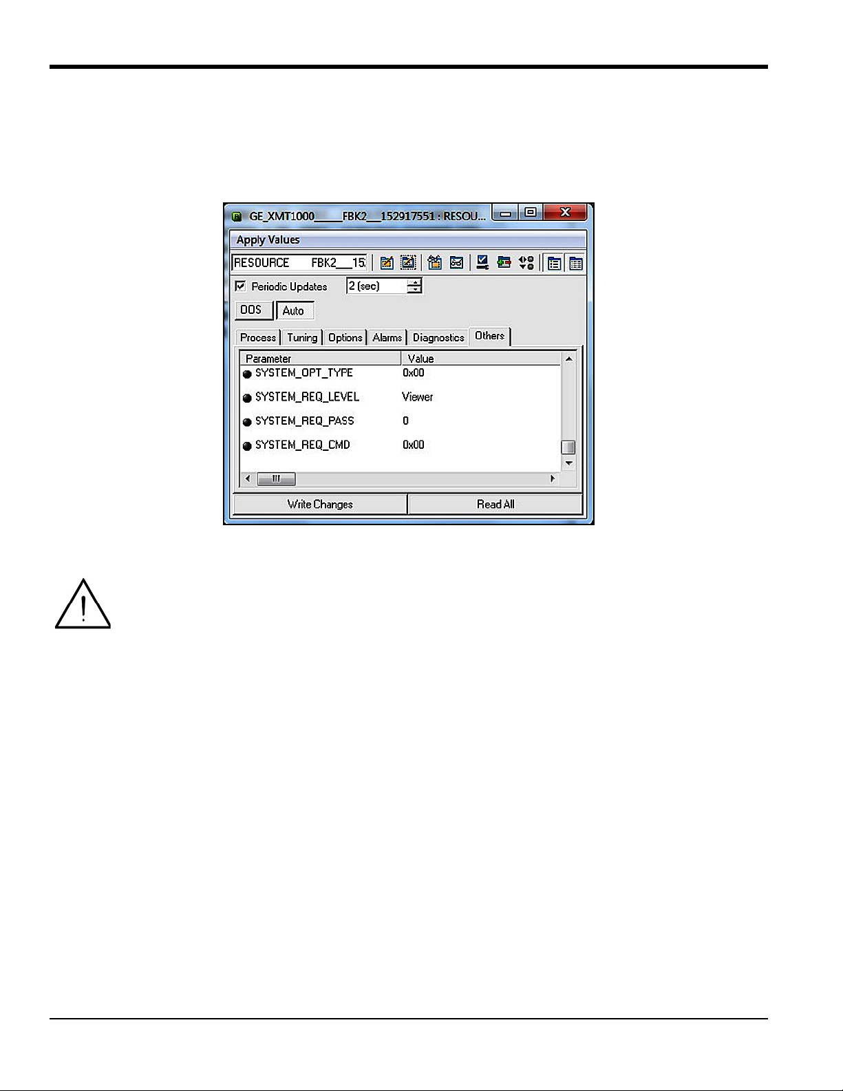
Appendix D. Foundation Fieldbus Communication
D.4.2 Password
A password must be entered to change XMT1000 system parameters. This can be done using Foundation Fieldbus.
There are different levels of security for different Passwords (
more detail on password levels. Figure 25 below shows the password fields in the XMT1000 Resource Block.
Admin or Operator). Please see the standard manual for
Figure 25: Password Fields in XMT1000 Resource Block
Attention! Before entering a password, make sure the
To Enter configuration mode, complete the following steps:
1. Select the
2. Select
3. Select
4. Enter the
5. Select
6. Select
7. Click on the
8. Verify that
Resource Block > Others tab.
SYSTEM_OPT_TYPE and set to Option FI.
SYSTEM_REQ_LEVEL and set to Admin or Operator.
Admin or Operator password into the SYSTEM_REQ_PASS field.
Cancel from the SYSTEM_REQ_CMD drop down box.
Login from the SYSTEM_REQ_CMD drop down box.
Write Changes button.
S1:In Config Mode appears on XMT1000 display. You should now be able to edit fields with Admin
privileges.
XMIT_TB transducer block is in active mode.
64 PanaFlow™ XMT1000 User’s Manual
Page 77

D.4.2 Password (cont.)
To Edit the fields in the Transducer Blocks, complete the following steps:
Appendix D. Foundation Fieldbus Communication
1. Select or enter the
2. Click on the
3. Return to the
4. Click on the
To Exit configuration mode, complete the following steps:
1. Select
2. Click on the
Note: The XMT1000 will automatically exit configuration mode after 5 minutes of inactivity.
Cancel from the SYSTEM_REQ_CMD drop down box.
new value.
Write Changes button.
Resource Block > Others tab and select Commit from the SYTEM_REQ_COM drop down box
Write Changes button.
Write Changes button.
D.4.3 NAMUR NE107
The NAMUR NE107 recommendation specifies that detailed device-specific diagnostics are summarized as four simple
status signals. The diagnostics are set to defaults by GE, but they can be modified to any other level by the user. The
four status signals are:
• Failed: This category is typically used for hardware or software failures. The meter output is not valid. Consult
with the factory for a resolution.
• Offspec: This category is typically used for application, installation, or process problems. Consult the
troubleshooting section of this appendix or contact GE customer service for assistance.
• Check: This category means the output of the device is invalid due to on-going work on the device, such as
programming, etc.
• Maintenance: This category is typically used to assign parameters that are in good status but which may fall
out of specification due to some process condition or wear factor. There are no diagnostics set as default in this
category.
The status signals (see Figure 26 below) can either be reported as errors (
MASK). There are no default settings for the MASK bits.
(
Figure 26: NAMUR NE107 Configuration in Resource Block
ACTIVE) or masked when the error occurs
PanaFlow™ XMT1000 User’s Manual 65
Page 78

Appendix D. Foundation Fieldbus Communication
D.4.3 NAMUR NE107 (cont.)
The NAMUR NE107 Errors and their Default Categories in the XMT1000 Resource Block are listed in Ta bl e 7 below.
Table 7: NAMUR NE107 Errors and XMT1000 Default Categories
Error Sub-Error Description Default Category
CRC Configuration Error Persistent Parameter CRC Fault Failed
Software Failure Stack Overflow failure Failed
Sequence or Windowed Watch Dog failure Failed
Software fault Failed
Device Initialization Failure Initialization failed Failed
Hardware Failure ADC Bit Test Fault Failed
VGA test Fault Failed
Clock Frequency Fault Failed
CPU test Fault Failed
Invariable Flash Memory Fault Failed
Variable Memory Fault Failed
FPGA Configuration CRC fault Failed
Temperature Test Fault Failed
Driver Failure Failed
Watch Dog failure Failed
DSP Hardware Errors Failed
Default ISR (DSP Exception) Failed
DSP Exception Failed
Modbus Communication Loss No Modbus communication Failed
Sensor Value out of Range VelocityWarning Offspec
Device not calibrated NotCalibrated Offspec
Sensor Measurement Error SingleChAccuracy Offspec
MultiChAccuracy Offspec
ActiveTw Offspec
CycleSkip Offspec
Amplitude Offspec
SignalQuality Offspec
VelocityRange Offspec
SoundSpeed Offspec
SNR Offspec
Device in Configuration Mode In Configuration Mode - Indication Check
Unsupported Parameter Warning Unsupported Parameter - Warning Check
Invalid Parameter Range Warning Invalid Parameter Range - Warning Check
Invalid Request Warning Invalid request - Warning Check
Invalid User Warning Invalid User - Warning Check
66 PanaFlow™ XMT1000 User’s Manual
Page 79

Appendix D. Foundation Fieldbus Communication
D.5 XMIT Transducer Block
The XMIT transducer block contains parameters that can be transmitted onto the Fieldbus via the AI block. The user can
view real time data and select the units for each of the parameters (see Figure 27 below).
Figure 27: Measurement Parameters and Units in XMIT Transducer Block
PanaFlow™ XMT1000 User’s Manual 67
Page 80

Appendix D. Foundation Fieldbus Communication
D.5.1 Units
The measurement parameters found on the XMIT Transducer Block have several selectable units. Tab le 8 below lists the
available units for each parameter.
Note: The units can only be changed using an
Transducer Block
and the AI Block.
Admin password. Make sure the selected units agree between the XMIT
Table 8: Available Parameters and Units in XMIT Transducer Block
Parameter Units
Density
Volumetric Flow (Act)
3
, kg/L, g/ml, kg/m3, lb/in3, lb/ft3, lb/gal
g/m
3
/s, m3/m, m3/h, m3/d, L/s, L/min, L/h, ML/d, CFS, CFM, CFH, ft3/d, gal/s, GPM,
m
gal/h, gal/d, ImpGal/s, ImpGal/min, ImpGal/h, ImpGal/d, bbl/s, bbl/min, bbl/h, bbl/d,
kgal/min, kgal/h, kgal/d, kbbl/min, kbbl/h, kbbl/d, ac-ft/m, ac-ft/h, ac-ft/d
Mass Flow kg/s, kg/min, kg/h, kg/d, t/s, t/min, t/h, t/d, lb/s, lb/min, lb/h, lb/d, Ston/s, Ston/min,
Ston/h, Ston/d, klb(US)/s, klb(US)/min, klb(US)/h, klb(US)/d
Velocity m/s, ft/s
Totals
3
, L, ft3, gallon, bbl, Mgal, Mft3, ImpGal, Mbbl, Ml, Mm3, ac-ft, ac-in, Sm3, SL, SCF
m
Temperature K, C, F, R
Pressure
2
kg-m
, Pa, Mpa, kPa, bar, mbar, torr, atm, psia, psig
68 PanaFlow™ XMT1000 User’s Manual
Page 81

Appendix D. Foundation Fieldbus Communication
D.6 Composite Transducer Block
The Composite Transducer Block provides the measurement values and programmable parameters that are common
to all three paths. Figure 28 below shows the
Measurements and Parameters that are available.
Composite Transducer Block and Table 9 on page 70 lists the
Note: The
R/W designation means that the parameter is writable in FF using an Admin password.
Figure 28: Composite Transducer Block
PanaFlow™ XMT1000 User’s Manual 69
Page 82

Appendix D. Foundation Fieldbus Communication
D.6 Composite Transducer Block (cont.)
Table 9: Available Measurement Values and Parameters in the Composite TB
Composite TB Measurements and Parameters Measurement Parameter
BATCH_FWD_TOTALS R
BATCH_REV_TOTALS R
BATCH_TOTAL_TIME R
SOUND_SPEED R
INVENTORY_FWD_TOTALS R
INVENTORY_REV_TOTALS R
INVENTORY_TOTAL_TIME R
MULTI_KFACTOR R
REYNOLDS_KFACTOR R
CURRENT_OPERATING_TEMP R
STANDARD_VOLUMETRIC R
BATCH_NET_TOTALS R
ERROR_STATUS R
HEALTH_CODE R
REPORTED_ERROR R
GATE_INPUT_STATE R
UNIT_TYPE_DENSITY_R R
UNIT_TYPE_VELOCITY_R R
UNIT_TYPE_TEMPERATURE_R R
PIPE_ID R/W
PIPE_OD R/W
PIPE_WALL_THICKNESS R/W
CORR_PEAK_LOW_LIMIT R/W
ANALOGOUT_PERCENTSCALE R/W
ACCELERATION_LIMIT R/W
AMP_DISC_MIN R/W
AMP_DISC_MAX R/W
KINEMATIC_VISCOSITY R/W
CALIBRATION_FACTOR R/W
ZERO_CUTOFF R/W
RESPONSE_TIME R/W
VELOCITY_LOW_LIMIT R/W
VELOCITY_HIGH_LIMIT R/W
VELOCITY_WARN_LOW_LIMIT R/W
70 PanaFlow™ XMT1000 User’s Manual
Page 83

Appendix D. Foundation Fieldbus Communication
Table 9: Available Measurement Values and Parameters in the Composite TB (cont.)
Composite TB Measurements and Parameters Measurement Parameter
VELOCITY_WARN_HIGH_LIMIT R/W
REFERENCE_DENSITY R/W
SOS_LOW_LIMIT, SOS_HIGH_LIMIT R/W
MULTIK_VELREY_1-12, MULTIK_KFACTOR_1-12 R/W
REYNOLDS_CORRECTION R/W
FLUID_SUPPLY_TEMPERATURE R
FLUID_RETURN_TEMPERATURE R
SOS_LOW_LIMIT R/W
SOS_HIGH_LIMIT R/W
MULTIK_VELREY R/W
MULTIK_KFACTOR R/W
PATHCONFIGURRATION R/W
HARDWARE_REVISION R
SOFTWARE_REVISION R
UMPU_SERIAL_NUMBER R
TOTALIZER_CMD R/W
SENSOR_SERIAL_NUMBER R
MULTIK_ACTIVE R/W
MULTIK_TYPE R/W
MULTIK_PAIRS R/W
KVINPUT_SELECTION R/W
ENABLE_ACTIVE_TW R/W
CALIBR_MODE_SELECTION R/W
PATH_ERROR_HANDLING R/W
UNIT_TYPE_DIMENSION R/W
UNIT_TYPE_TIME R/W
UNIT_TYPE_VISCOSITY R/W
UNIT_TYPE_STD_VOL R/W
SYSTEM_SERIAL_NUMBER R
FTPA_SERIAL_NUMBER R
VOLTAGE_SELECTION R/W
ATTENUATOR_SELECTION R/W
PanaFlow™ XMT1000 User’s Manual 71
Page 84

Appendix D. Foundation Fieldbus Communication
D.6.1 Clearing the Totalizer
Batch totals can be controlled through Foundation Fieldbus (see Figure 29 below). The user can start, stop, or reset
batch totalizers by setting the option on the
totalizers from the Foundation Fieldbus:
1. Verify that the gate and ground terminals on the Main PCB are connected.
TOTALIZER_CMD function of the Composite Transducer Block. To set the
2. Program the
CALIBR_MODE_SELECTION parameter on the Composite Transducer Block to Gate Input.
After these steps are complete, you can control the batch totalizer (start, stop, or reset) by selecting the desired option
TOTALIZER_CMD and writing the changes to the meter. No password is required for this function.
on
IMPORTANT: The Inventory Totalizer can only be reset at the factory.
Figure 29: TOTALIZER_CMD Function on Composite TB
72 PanaFlow™ XMT1000 User’s Manual
Page 85

Appendix D. Foundation Fieldbus Communication
D.7 Channel Transducer Block
The CH1, CH2 and CH3 transducer blocks show the measurement values and programmable parameters for each of the
three paths. Figure 30 below shows the
and parameters that are available.
Channel Transducer Block, and Table 10 on page 74 lists the measurements
Note: The
R/W designation means that the parameter is writable in FF using an Admin password.
Figure 30: Channel Transducer Block
PanaFlow™ XMT1000 User’s Manual 73
Page 86

Appendix D. Foundation Fieldbus Communication
D.7 Channel Transducer Block (cont.)
Table 10: Available Measurement Values and Parameters in the Channel TB
Channel TB Measurements and Parameters Measurement Parameter
CH_SOUND_SPEED R
CH_TRANSIT_TIME_UP R
CH_TRANSIT_TIME_DN R
CH_DELTA_T R
CH_UP_SIGNAL_QUALITY R
CH_DN_SIGNAL_QUALITY R
CH_UP_AMP_DISC R
CH_DN_AMP_DISC R
CH_GAIN_UP R
CH_GAIN_DN R
CH_SNR_UP R
CH_SNR_DN R
CH_UP_PEAK R
CH_DN_PEAK R
CH_PEAK_PCT_UP R
CH_PEAK_PCT_DN R
CH_NUM_ERRRORS_OF_16 R
CH_WEIGHT_FACTOR R/W
CH_TBC R/W
CH_TW R/W
CH_PATH_LENGTH R/W
CH_AXIAL_LENGTH R/W
CH_TRANSMIT_DELAY R/W
CH_DELTA_T_OFFSET R/W
CH_PCT_PEAK R/W
CH_TRANSDUCER_TYPE R/W
CH_TRANSDUCER_FREQ R/W
CH_ERRORS_ALLOWED R/W
CH_TRANSDUCER_NUMBER R/W
CH_PATHCONFIGURATION R/W
74 PanaFlow™ XMT1000 User’s Manual
Page 87

Appendix D. Foundation Fieldbus Communication
D.8 Analog Input Block
The Analog Input (AI) Block (see Figure 31 below) is designed as a generalized signal conditioning function. The
output from an
Transducer Block and provides additional functions such as scaling, filtering, alarm generation, and trending.
AI block can be connected to the Fieldbus. The AI block receives and processes data measured by the
Figure 31: Analog Input (AI) Block
D.9 PID Block
The PID function offers control based on a programmable algorithm. The PID function block may be used with a valve
to control flow.
Note: See Foundation Fieldbus Specifications for more detail on use of the
PanaFlow™ XMT1000 User’s Manual 75
PID Block.
Page 88

Appendix D. Foundation Fieldbus Communication
D.10 Error Handling
The flow meter publishes the error status on the Fieldbus along with the real data. The error status can be seen in the
CH_x_Reported Error parameter on the Channel Transducer Block. In addition, the Quality parameter shown with
each of the process variables reports the error. In Figure 32 below, the
Note: For more information on the actual measurement errors and possible causes, see Chapter 3, Error Codes and
Troubleshooting.
CH1_REPORTED_ERROR shows as E1.
Figure 32: Reported Error
76 PanaFlow™ XMT1000 User’s Manual
Page 89

Appendix D. Foundation Fieldbus Communication
D.10 Error Handling (cont.)
Whenever the meter is in measurement error, the quality bit for the published parameter shows bad quality (see
Figure 33 below). To change the quality bit to good, the measurement error at the meter must be removed.
Notice the
QUALITY.STATUS field shows as Bad and the SUBSTATUS field shows as Sensor Failure. This information
indicates a measurement error which must be corrected.
Figure 33: Quality Bit Error
PanaFlow™ XMT1000 User’s Manual 77
Page 90

Appendix D. Foundation Fieldbus Communication
Jumper P5
D.11 Simulation Mode
Simulation mode allows the user to test the FF implementation without the instrument providing real data. The meter
PCB is shipped with simulation mode disabled. To enable simulation mode, complete the following steps:
CAUTION! To prevent damage to the electronic components, always use
handling printed circuit boards.
1. Remove the PCB from the meter.
2. Locate the jumper
3. Move the
P5 jumper to the left one place (pins 2 & 3) to enable simulation mode.
P5 (see Figure 34 below).
4. Re-install the PCB into meter
5. Verify that the
Block error field in the Resource Block shows SimulationActive status.
ESD protection whenever
Figure 34: P5 on XMT1000 PCB
78 PanaFlow™ XMT1000 User’s Manual
Page 91

Appendix D. Foundation Fieldbus Communication
D.12 Fieldbus Troubleshooting Guide
See Tab le 11 below for suggested solution to possible Fieldbus problems.
Table 11: XMT1000 FF Troubleshooting Guide
Problem Presumed Cause Remedy
Communication between DCS and
XMT1000 FF cannot be established
Communication with the XMT1000
FF is frequently cut off.
A value cannot be written to a
parameter in the XMT1000 FF.
Wiring unconnected, broken or
shorted
The power is off or the power supply
Correct wiring between XMT1000
and spur device coupler.
Supply proper voltage
voltage is less than 9 V
The address detection range is not
correctly set in the DCS
The fieldbus is experiencing a large
amount of noise.
Correct address detection range default address for XMT1000 is 0x17
Using an oscilloscope or another
fieldbus health monitor to check the
waveform on the fieldbus.
Missing terminators on the bus,
incorrect terminator placement or
extra terminators.
Refer to FOUNDATION Fieldbus
specifications for a full discussion of
terminator requirements.
Not in configuration mode. Enter correct "Admin" password in
Resource block - verify "S1 configuration mode" appears on
XMT1000 UI
You have attempted to write a value
Check the setting range of parameters.
outside the valid range.
The present mode does not allow write
Change the target mode.
access.
The actual mode of a function block
differs from the target mode.
A block's dynamic parameters do not
update.
The jumper is in write protected
configuration.
Contact factory for write protect
jumper configuration
Resource block in OOS. Change the target mode of the
Resource Block to Auto.
Schedules that define when function
blocks execute are not set correctly.
The transducer block is not in Auto
mode.
Set the schedules using a
configuration tool.
Change the target mode of the
transducer block to Auto.
XMT1000 is powered down Verify the XMT1000 is powered on
and measuring properly
XMT1000 does not recognize the FF
PCB
Check Options menu on XMT1000 UI
for Fieldbus option - if it appears the
meter knows it is present
PanaFlow™ XMT1000 User’s Manual 79
Page 92

Appendix D. Foundation Fieldbus Communication
D.13 DPI620 FF Modular Communicator
For local diagnostic capability with the XMT1000 FF option, GE Measurement and Control recommends the
DPI620G-FF Genii advanced modular calibrator and HART/Fieldbus communicator. The calibrator is available in an IS
version as well (
Image Model PN Description Key Benefits
DPI620G-IS-FF). Ta bl e 12 below lists the models, description and key benefits.
Table 12: DPI620 Genii Models
DPI620G-FF Genii advanced
modular calibrator and
HART/Fieldbus
communicator
• Fully featured communicators for device
configuration, trimming and calibration
• Complete device description (DD) libraries
• Internal power hub
• Free software and DD updates via simple
web download
DPI620G-IS-FF Genii intrinsically safe
advanced modular
calibrator and
HART/Fieldbus
communicator
Attention! For more information, see the
https://www.gemeasurement.com/test-calibration/calibrators/dpi-620-genii-multifunction-calibrator
DPI620 website:
80 PanaFlow™ XMT1000 User’s Manual
Page 93

Index
Index
A
Analog Outputs
Wiring
Analog Outputs (Slot 0)
Connecting
Arrow Keys . . . . . . . . . . . . . . . . . . . . . . . . . . . . . . 14
. . . . . . . . . . . . . . . . . . . . . . . . . . . . . . . . . . 9
. . . . . . . . . . . . . . . . . . . . . . . . . . . . . . 9
C
Cable
Transducers
Cable Lengths . . . . . . . . . . . . . . . . . . . . . . . . . . . . . . 6
Calibration Port
Wiring
CE Marking Compliance . . . . . . . . . . . . . . . . . . . . . . 1
Channels
see Paths
Communication Error String
Connecting
See Part Name
Corrosion, Transducers
. . . . . . . . . . . . . . . . . . . . . . . . . . . . . . 6
. . . . . . . . . . . . . . . . . . . . . . . . . . . . . . . . . 10
. . . . . . . . . . . . . . . . . . 25
. . . . . . . . . . . . . . . . . . . . . . 29
D
Data Logging . . . . . . . . . . . . . . . . . . . . . . . . . . . . . 31
Diagnostics . . . . . . . . . . . . . . . . . . . . . . . . . . . . . . . 27
Digital Outputs
Wiring
Down Arrow Key . . . . . . . . . . . . . . . . . . . . . . . . . . 14
. . . . . . . . . . . . . . . . . . . . . . . . . . . . . . . . . 10
E
Electrical Connections . . . . . . . . . . . . . . . . . . . . . . . . 7
Electronics Classifications . . . . . . . . . . . . . . . . . . . . 33
Electronics Enclosures . . . . . . . . . . . . . . . . . . . . . . . 32
Electronics Mounting. . . . . . . . . . . . . . . . . . . . . . . . 33
Enter Key . . . . . . . . . . . . . . . . . . . . . . . . . . . . . . . . 14
Error Header . . . . . . . . . . . . . . . . . . . . . . . . . . . . . . 25
Error String, Communication . . . . . . . . . . . . . . . . . . 25
Error String, Flow . . . . . . . . . . . . . . . . . . . . . . . . . . 26
Escape Key . . . . . . . . . . . . . . . . . . . . . . . . . . . . . . . 14
F
Flow Error String . . . . . . . . . . . . . . . . . . . . . . . . . . 26
Flowcell Problems . . . . . . . . . . . . . . . . . . . . . . . . . . 27
Fluid . . . . . . . . . . . . . . . . . . . . . . . . . . . . . . . . . . 27
Pipe . . . . . . . . . . . . . . . . . . . . . . . . . . . . . . . . . . 28
Fluid
Physical Requirements
Problems . . . . . . . . . . . . . . . . . . . . . . . . . . . . . . . 27
Soundspeed . . . . . . . . . . . . . . . . . . . . . . . . . . . . . 27
Fluid Problems . . . . . . . . . . . . . . . . . . . . . . . . . . . . 27
Frequency Output
Wiring
. . . . . . . . . . . . . . . . . . . . . . . . . . . . . . . . . 10
. . . . . . . . . . . . . . . . . . . . . 27
G
Grounding. . . . . . . . . . . . . . . . . . . . . . . . . . . . . . . . . 7
I
Input Voltage. . . . . . . . . . . . . . . . . . . . . . . . . . . . . . 12
Inputs/Outputs. . . . . . . . . . . . . . . . . . . . . . . . . . . . . 32
K
Keypad . . . . . . . . . . . . . . . . . . . . . . . . . . . . . . . . . . 32
Keypad Program, Exiting if Unused . . . . . . . . . . . . . 14
L
Languages. . . . . . . . . . . . . . . . . . . . . . . . . . . . . . . . 32
Leaks, Transducers . . . . . . . . . . . . . . . . . . . . . . . . . 29
Left Arrow Key . . . . . . . . . . . . . . . . . . . . . . . . . . . . 14
Line Power
Wiring
LVD Statement . . . . . . . . . . . . . . . . . . . . . . . . . . . . . 6
. . . . . . . . . . . . . . . . . . . . . . . . . . . . . . . . . 12
M
Magnetic Keypad, Using . . . . . . . . . . . . . . . . . . . . . 13
Modbus
Wiring
. . . . . . . . . . . . . . . . . . . . . . . . . . . . . . . . . 11
O
Operating Temperature . . . . . . . . . . . . . . . . . . . . . . 33
P
PanaFlow HT
Electrical Connections
Unpacking. . . . . . . . . . . . . . . . . . . . . . . . . . . . . 2, 3
Wiring Diagram. . . . . . . . . . . . . . . . . . . . . . . . . . . 8
PanaFlow Z3
Magnetic Keypad
Passcodes . . . . . . . . . . . . . . . . . . . . . . . . . . . . . . . . 14
Paths. . . . . . . . . . . . . . . . . . . . . . . . . . . . . . . . . . . . 32
. . . . . . . . . . . . . . . . . . . . . . 7
. . . . . . . . . . . . . . . . . . . . . . . . . 13
PanaFlow™ XMT1000 User’s Manual 81
Page 94

Index
Pipe
Measurements
Problems . . . . . . . . . . . . . . . . . . . . . . . . . . . . . . . 28
Pipe Problems . . . . . . . . . . . . . . . . . . . . . . . . . . . . . 28
Power
Connecting
Terminal Bl o ck . . . . . . . . . . . . . . . . . . . . . . . . . . 12
Power Consumption . . . . . . . . . . . . . . . . . . . . . . . . 32
Power Supplies . . . . . . . . . . . . . . . . . . . . . . . . . . . . 32
Problems, Transducers . . . . . . . . . . . . . . . . . . . . . . . 29
. . . . . . . . . . . . . . . . . . . . . . . . . . . 28
. . . . . . . . . . . . . . . . . . . . . . . . . . . . . 12
R
Registration. . . . . . . . . . . . . . . . . . . . . . . . . . . . . . . vii
Right Arrow Key . . . . . . . . . . . . . . . . . . . . . . . . . . . 14
S
Safety
Auxiliary Equipment
General Issues . . . . . . . . . . . . . . . . . . . . . . . . . . . vii
Personal Equipment . . . . . . . . . . . . . . . . . . . . . . viii
Safety Codes . . . . . . . . . . . . . . . . . . . . . . . . . . . . . . . 1
Services . . . . . . . . . . . . . . . . . . . . . . . . . . . . . . . . . vii
Slot 0
See Analog Outputs (Slot 0)
Soundspeed
. . . . . . . . . . . . . . . . . . . . . . . . . . . . . . . . . . 27
Fluid
Specifications . . . . . . . . . . . . . . . . . . . . . . . . . . . . . 31
. . . . . . . . . . . . . . . . . . . . . viii
T
Terminal Bl o ck
Analog Outputs - I/O
Power - TB1 . . . . . . . . . . . . . . . . . . . . . . . . . . . . 12
Terms and Conditions . . . . . . . . . . . . . . . . . . . . . . . vii
Totalizer Output
Wiring
Transducer Cables . . . . . . . . . . . . . . . . . . . . . . . . . . . 6
Transducer Problems . . . . . . . . . . . . . . . . . . . . . . . . 29
. . . . . . . . . . . . . . . . . . . . . . . . . . . . . . . . . 10
. . . . . . . . . . . . . . . . . . . . . . . 9
Transducers
Cables
Corrosion . . . . . . . . . . . . . . . . . . . . . . . . . . . . . . 29
Internal Damage . . . . . . . . . . . . . . . . . . . . . . . . . 29
Leaks . . . . . . . . . . . . . . . . . . . . . . . . . . . . . . . . . 29
Location . . . . . . . . . . . . . . . . . . . . . . . . . . . . . . . . 5
Physical Damage . . . . . . . . . . . . . . . . . . . . . . . . . 29
Placement . . . . . . . . . . . . . . . . . . . . . . . . . . . . . . 28
Problems . . . . . . . . . . . . . . . . . . . . . . . . . . . . . . . 29
Replacement . . . . . . . . . . . . . . . . . . . . . . . . . . . . 29
Typographical Conventions . . . . . . . . . . . . . . . . . . . vii
. . . . . . . . . . . . . . . . . . . . . . . . . . . . . . . . . . 6
U
Unpacking . . . . . . . . . . . . . . . . . . . . . . . . . . . . . . 2, 3
Up Arrow Key. . . . . . . . . . . . . . . . . . . . . . . . . . . . . 14
V
Voltage, Input . . . . . . . . . . . . . . . . . . . . . . . . . . . . . 12
W
Warranty . . . . . . . . . . . . . . . . . . . . . . . . . . . . . . . . . vii
Wiring
Analog Outputs
Calibration Port . . . . . . . . . . . . . . . . . . . . . . . . . . 10
CE Marking Compliance . . . . . . . . . . . . . . . . . . . . 1
Digital Outputs . . . . . . . . . . . . . . . . . . . . . . . . . . 10
Frequency Output . . . . . . . . . . . . . . . . . . . . . . . . 10
Line Power . . . . . . . . . . . . . . . . . . . . . . . . . . . . . 12
Modbus/Service Port . . . . . . . . . . . . . . . . . . . . . . 11
Option Card . . . . . . . . . . . . . . . . . . . . . See Card Name
Terminal Block . . . . . . . . . . . . . . . . . See Block Name
Totalizer (Pulse) Output
Wiring Connection . . . . . . . . . . . . . . . . . . . . . . . . . 32
Wiring Diagram . . . . . . . . . . . . . . . . . . . . . . . . . . . . 8
. . . . . . . . . . . . . . . . . . . . . . . . . . . 9
. . . . . . . . . . . . . . . . . . . . 10
82 PanaFlow™ XMT1000 User’s Manual
Page 95

Page 96

Customer Support Centers
U.S.A.
The Boston Center
1100 Technology Park Drive
Billerica, MA 01821
U.S.A.
Tel: 800 833 9438 (toll-free)
978 437 1000
E-mail: custcareboston@ge.com
Ireland
Sensing House
Shannon Free Zone East
Shannon, County Clare
Ireland
Tel: +353 61 61470200
E-mail: gesensingsnnservices@ge.com
910-313 Rev. A
An ISO 9001-2008 Certified Company
www.gemeasurement.com/quality-certifications
www.gemeasurement.com
©2017 General Electric Company. All rights reserved.
Technical content subject to change without notice.
 Loading...