

Page 1
GE
Sensing & Inspection Technologies
XDP
Panametrics Explosion-Proof Display
Applications
Explosion-proof display/controller for use with:
• XMO2 thermoparamagnetic oxygen transmitter
• XMTC thermal conductivity hydrogen/gas
transmitter
• Any other 4 to 20 mA output transmitter
Features
• Explosion-proof for Class I, Division 1, Group B, C &
D hazardous areas
• Flameproof
• Infrared (IR) through-the-glass keypad
• Universal AC input
• 24 VDC power supply for XMO2, XMTC or O2X1
• Software for measurement of percent or ppm
oxygen or hydrogen
• Three-curve software for hydrogen-cooled
generator
• Programmable process relay contacts
II 2 GD EEx d IIC T6 T85°C
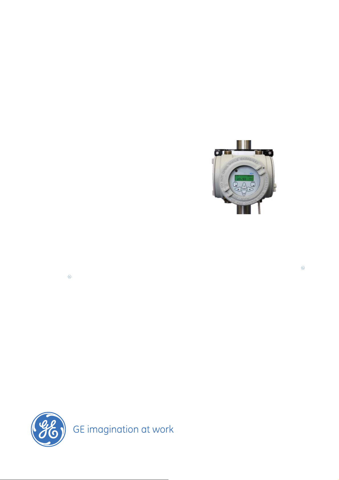
XDP Explosion-Proof Display
The XDP explosion-proof display provides the
measurement of percent or ppm oxygen or
hydrogen gas. The explosion-proof XDP is certifi ed
for use in Class I, Division 1, Groups B, & D, and
GD EEx d IIC T6 hazardous areas.
The XDP features advanced microprocessor-based
electronics, an infrared, through-the-glass keypad,
a universal power supply (85 to 264 VAC), one 0/4
to 20 mA or 0 to 2 VDC analog out put, four process
alarms, and a fault alarm.
II 2
Auto-verifi cation/Auto-calibration
The XDP provides long-term, hands-off operation
with this optional feature. When initiated, the XDP
controls solenoid valves in the sample system to
bring zero and span gases to the transmitter. Then
the XDP software compares calibration gas readings
with factory data to verify proper calibration. If an
adjustment is necessary, the XDP makes corrections
automatically and notifi es the user via the front
panel display and alarm contacts.
Page 2
XDP Specifi cations
Output Power Supply
24 VDC ±2 VDC at 1.2 Amp
Functional
Analog Output
Linearized isolated 4 to 20 mA, 0 to 20 mA or NAMUR
user-selectable, fi eld-programmable output for any
range from 0 to 100 percent or 0 to 10,000 ppm.
Input Power
85 to 264 VAC, 47 to 63 Hz, 40 W
Fuse
1.25 A
Analog Input
4 to 20 mA
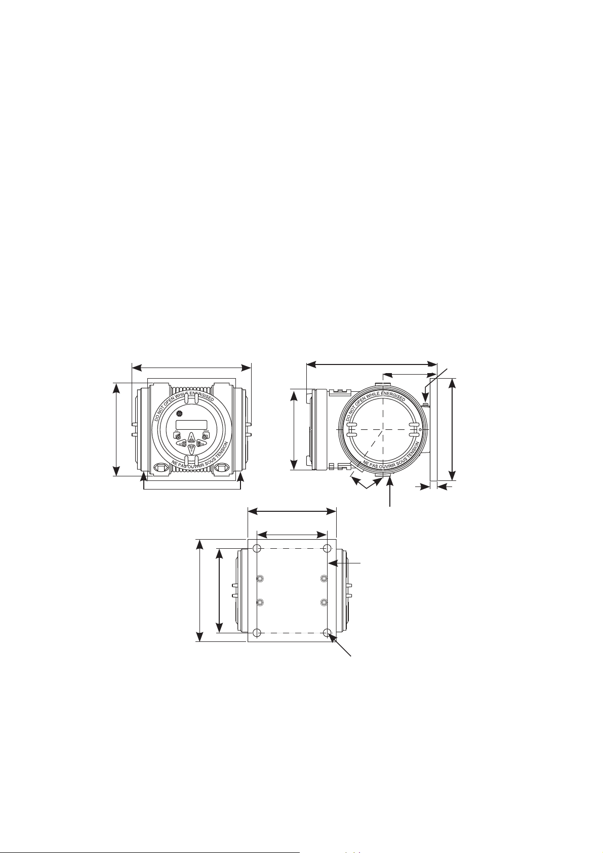
Front View Side View
8 in (210 mm)
Ambient Temperature Range
14°F to 140°F (–10°C to 60°C)
Keypad
Infrared, through the glass, six keys
Display
Four-line, backlit liquid crystal display
Display Accuracy
±0.25% of full scale
Relay Outputs
• Contact ratings: 2 A, 28 VDC, SPDT
• Programmable as fail-safe or nonfail-safe
9 in (229.8 mm)
3.7 in (96 mm)
External ground
1.365 in
(34.67 mm)
XDP
7 in (180.3 mm)
5.8 in (148.5 mm)
5.6 in (142.2 mm)
6 in (155.7 mm)
4.8 in (123.9 mm)
Back View
XDP dimensions in inches (mm)
35°
3/4 in NPT
conduit port
Mounting plate
0.53 in (13.4 mm)
mounting holes
7 in (180.3 mm)
0.5 in
(12.7 mm)
Page 3

Standard Software for O2 Analysis
Physical
Measurement Range Examples
• 0 to 10; 100; 1,000; or 10,000 ppm O
• 0% to 1%; 10%; 21%; 25%; or 100% O
2
2
Relays
• Four process alarms
• One fault alarm
• Two automatic calibration contacts
• Two calibration alarms
Hydrogen-Cooled Generator Software
Three Ranges
• 0% to 100% H2 in air
• 0% to 100% H2 in CO
• 0% to 100% air in CO
Relays
• Two process alarms
• One fault alarm
• One normal alarm
2
2
Dimensions (w x h x d)
9 in x 10 in x 9 in. (229 mm x 254 mm x 229 mm)
Weight
15 lb (6.8 kg)
Environmental
• Weatherproof enclosure Type 4X/IP66
• Explosion-proof Type 7 enclosure: FM/CSA Class I,
Division 1, Group B, C & D
• Flameproof: KEMA 01ATEX2128 II 2 GD EEx d IIC T6
T85°C
European Compliance
Complies with EMC Directive 89/336/EEC, 73/23/EEC LVD
(Installation Category II, Pollution Degree 2)
Conduit Entry
Six 3/4 in NPTF conduit ports
Mounting Holes
Four 3/8 in (10 mm) holes
Order Information
Record selected option in blank indicated at bottom of
form.
XDP Explosion-proof Display for Use with XMO2, XMTC and O2X1
Package
2 Explosion-proof/weatherproof enclosure
Power
1 100 VAC
2 115 VAC
3 230 VAC
4 240 VAC
Keypad
1 IR keypad
Confi guration
1 Standard
2 Hydrogen-cooled generator
XDP _ _ _ _ Use this number to order product
Page 4

www.gesensinginspection.com
920-028D
© 2008 General Electric Company. All Rights Reserved. Specifi cations are subject to change without notice. GE is a registered trademark of General Electric Company. Other company or product
names mentioned in this document may be trademarks or registered trademarks of their respective companies, which are not affi liated with GE.
 Loading...