

Page 1

GE Industrial
Sensing
Model UTX878
Ultrasonic Flowmeter
Abridged Manual
Page 2
GE Industrial
Sensing
Model UTX878
Ultrasonic Flowmeter
Abridged Manual
914-253A
June 2004
Model UTX878 is a GE Panametrics product. GE Panametrics has joined other GE high-technology sensing
businesses under a new name—GE Industrial Sensing.
Page 3

June 2004
Table of Contents
Warranty . . . . . . . . . . . . . . . . . . . . . . . . . . . . . . . . . . . . . . . . . . . . . . . . . . . . . . . . . . . . . . . . . . . . . . . . . . . . . . . . . . . . v
Return Policy. . . . . . . . . . . . . . . . . . . . . . . . . . . . . . . . . . . . . . . . . . . . . . . . . . . . . . . . . . . . . . . . . . . . . . . . . . . . . . . . . v
Introduction . . . . . . . . . . . . . . . . . . . . . . . . . . . . . . . . . . . . . . . . . . . . . . . . . . . . . . . . . . . . . . . . . . . . . . . . . . . . . . . . . 1
Unpacking . . . . . . . . . . . . . . . . . . . . . . . . . . . . . . . . . . . . . . . . . . . . . . . . . . . . . . . . . . . . . . . . . . . . . . . . . . . . . . . . . . . 2
Site Considerations. . . . . . . . . . . . . . . . . . . . . . . . . . . . . . . . . . . . . . . . . . . . . . . . . . . . . . . . . . . . . . . . . . . . . . . . . . . 2
Electronics Enclosure Location . . . . . . . . . . . . . . . . . . . . . . . . . . . . . . . . . . . . . . . . . . . . . . . . . . . . . . . . . . . . 2
Transducer Location. . . . . . . . . . . . . . . . . . . . . . . . . . . . . . . . . . . . . . . . . . . . . . . . . . . . . . . . . . . . . . . . . . . . . . 3
Cable Lengths. . . . . . . . . . . . . . . . . . . . . . . . . . . . . . . . . . . . . . . . . . . . . . . . . . . . . . . . . . . . . . . . . . . . . . . . . . . . 3
Transducer Cables . . . . . . . . . . . . . . . . . . . . . . . . . . . . . . . . . . . . . . . . . . . . . . . . . . . . . . . . . . . . . . . . . . . . . . . 3
Mounting the UTX878 Electronics Enclosure . . . . . . . . . . . . . . . . . . . . . . . . . . . . . . . . . . . . . . . . . . . . . . . . . . . 3
Making the Electrical Connections . . . . . . . . . . . . . . . . . . . . . . . . . . . . . . . . . . . . . . . . . . . . . . . . . . . . . . . . . . . . 4
Preparing the Unit Before Making Electrical Connections . . . . . . . . . . . . . . . . . . . . . . . . . . . . . . . . . . . 4
Wiring the Line Power . . . . . . . . . . . . . . . . . . . . . . . . . . . . . . . . . . . . . . . . . . . . . . . . . . . . . . . . . . . . . . . . . . . . 6
Unlocking and Locking the UTX878 . . . . . . . . . . . . . . . . . . . . . . . . . . . . . . . . . . . . . . . . . . . . . . . . . . . . . . . . . . . 7
Unlocking the UTX878 . . . . . . . . . . . . . . . . . . . . . . . . . . . . . . . . . . . . . . . . . . . . . . . . . . . . . . . . . . . . . . . . . . . . 7
Locking the UTX878 . . . . . . . . . . . . . . . . . . . . . . . . . . . . . . . . . . . . . . . . . . . . . . . . . . . . . . . . . . . . . . . . . . . . . . 8
Programming the UTX878 . . . . . . . . . . . . . . . . . . . . . . . . . . . . . . . . . . . . . . . . . . . . . . . . . . . . . . . . . . . . . . . . . . . . 9
Activating a Channel/Path (Status) . . . . . . . . . . . . . . . . . . . . . . . . . . . . . . . . . . . . . . . . . . . . . . . . . . . . . . . . 9
Entering Transducer Parameters. . . . . . . . . . . . . . . . . . . . . . . . . . . . . . . . . . . . . . . . . . . . . . . . . . . . . . . . . . . . . 10
Entering Pipe Parameters. . . . . . . . . . . . . . . . . . . . . . . . . . . . . . . . . . . . . . . . . . . . . . . . . . . . . . . . . . . . . . . . . . . . 11
Entering the Pipe Material . . . . . . . . . . . . . . . . . . . . . . . . . . . . . . . . . . . . . . . . . . . . . . . . . . . . . . . . . . . . . . . 11
Entering Pipe Lining Data . . . . . . . . . . . . . . . . . . . . . . . . . . . . . . . . . . . . . . . . . . . . . . . . . . . . . . . . . . . . . . . . 13
iii
Page 4

June 2004
Table of Contents (cont.)
Entering Fluid Data. . . . . . . . . . . . . . . . . . . . . . . . . . . . . . . . . . . . . . . . . . . . . . . . . . . . . . . . . . . . . . . . . . . . . . . . . . 14
Entering Fluid Type. . . . . . . . . . . . . . . . . . . . . . . . . . . . . . . . . . . . . . . . . . . . . . . . . . . . . . . . . . . . . . . . . . . . . . 14
Entering Reynolds Correction Data. . . . . . . . . . . . . . . . . . . . . . . . . . . . . . . . . . . . . . . . . . . . . . . . . . . . . . . 15
Entering Path Data. . . . . . . . . . . . . . . . . . . . . . . . . . . . . . . . . . . . . . . . . . . . . . . . . . . . . . . . . . . . . . . . . . . . . . . . . . 17
Installing the Transducers . . . . . . . . . . . . . . . . . . . . . . . . . . . . . . . . . . . . . . . . . . . . . . . . . . . . . . . . . . . . . . . . . . . 18
Setting Transducer Spacing. . . . . . . . . . . . . . . . . . . . . . . . . . . . . . . . . . . . . . . . . . . . . . . . . . . . . . . . . . . . . . 18
Installing the Transducers on the Pipe. . . . . . . . . . . . . . . . . . . . . . . . . . . . . . . . . . . . . . . . . . . . . . . . . . . . 19
Wiring the Transducers. . . . . . . . . . . . . . . . . . . . . . . . . . . . . . . . . . . . . . . . . . . . . . . . . . . . . . . . . . . . . . . . . . 20
Adjusting the 4-20 mA Loop . . . . . . . . . . . . . . . . . . . . . . . . . . . . . . . . . . . . . . . . . . . . . . . . . . . . . . . . . . . . . . . . . 21
Entering Global Units . . . . . . . . . . . . . . . . . . . . . . . . . . . . . . . . . . . . . . . . . . . . . . . . . . . . . . . . . . . . . . . . . . . . 21
Entering Base (Zero) and Span Output Values. . . . . . . . . . . . . . . . . . . . . . . . . . . . . . . . . . . . . . . . . . . . . . . . . 22
Entering Output Type and Units. . . . . . . . . . . . . . . . . . . . . . . . . . . . . . . . . . . . . . . . . . . . . . . . . . . . . . . . . . 22
Entering Base and Span Values . . . . . . . . . . . . . . . . . . . . . . . . . . . . . . . . . . . . . . . . . . . . . . . . . . . . . . . . . . 23
Trimming 4-20 mA Values via the Keypad . . . . . . . . . . . . . . . . . . . . . . . . . . . . . . . . . . . . . . . . . . . . . . . . 23
iv
Page 5

June 2004
Warranty Each instrument manufactured by GE Infrastructure Sensing, Inc. is
warranted to be free from defects in material and workmanship.
Liability under this warranty is limited to restoring the instrument to
normal operation or replacing the instrument, at the sole discretion of
GE Infrastructure Sensing, Inc.. Fuses and batteries are specifically
excluded from any liability. This warranty is effective from the date of
delivery to the original purchaser. If GE Infrastructure Sensing, Inc.
determines that the equipment was defective, the warranty period is:
• one year for general electronic failures of the instrument
• one year for mechanical failures of the sensor
If GE Infrastructure Sensing, Inc. determines that the equipment was
damaged by misuse, improper installation, the use of unauthorized
replacement parts, or operating conditions outside the guidelines
specified by GE Infrastructure Sensing, Inc., the repairs are not
covered under this warranty.
The warranties set forth herein are exclusive and are in lieu of
all other warranties whether statutory, express or implied
(including warranties or merchantability and fitness for a
particular purpose, and warranties arising from course of
dealing or usage or trade).
Return Policy If a GE Infrastructure Sensing, Inc. instrument malfunctions within the
warranty period, the following procedure must be completed:
1. Notify GE Infrastructure Sensing, Inc., giving full details of the
problem, and provide the model number and serial number of the
instrument. If the nature of the problem indicates the need for
factory service, GE Infrastructure Sensing, Inc. will issue a RETURN
AUTHORIZATION number (RA), and shipping instructions for the
return of the instrument to a service center will be provided.
2. If GE Infrastructure Sensing, Inc. instructs you to send your
instrument to a service center, it must be shipped prepaid to the
authorized repair station indicated in the shipping instructions.
3. Upon receipt, GE Infrastructure Sensing, Inc. will evaluate the
instrument to determine the cause of the malfunction.
Then, one of the following courses of action will then be taken:
• If the damage is covered under the terms of the warranty, the
instrument will be repaired at no cost to the owner and returned.
• If GE Infrastructure Sensing, Inc. determines that the damage is not
covered under the terms of the warranty, or if the warranty has
expired, an estimate for the cost of the repairs at standard rates
will be provided. Upon receipt of the owner’s approval to proceed,
the instrument will be repaired and returned.
v
Page 6

Introduction To ensure safe and reliable operation of the Model UTX878
Ultrasonic Flowmeter, the system must be installed and programmed
in accordance with the guidelines established by GE Infrastructure
Sensing, Inc. engineers. Those guidelines, explained in detail in this
guide, include the following topics:
• Unpacking the Model UTX878 system
• Selecting suitable sites for the electronics enclosure and the
transducers
• Installing the transducers
• Installing the electronics enclosure
• Wiring the electronics enclosure
• Programming the UTX878
!WARNING!
Be sure to follow all applicable local safety codes and
regulations for installing electrical equipment. Consult
company safety personnel or local safety authorities to
verify the safety of any procedure or practice.
June 2004
!ATTENTION EUROPEAN CUSTOMERS!
To meet CE Mark requirements, all cables must be installed
as described in Appendix B, CE Mark Compliance, of the
User’s Manual.
UTX878 Abridged Manual 1
Page 7
June 2004
Unpacking Carefully remove the electronics enclosure and the transducer/cable
assembly from the shipping containers. Before discarding any of the
packing materials, account for all components and documentation
listed on the packing slip. The discarding of an important item along
with the packing materials is all too common. If anything is missing
or damaged, contact the factory immediately for assistance.
Site Considerations Because the relative location of the transducers and the electronics
enclosure is important, use the guidelines in this section to plan the
UTX878 installation.
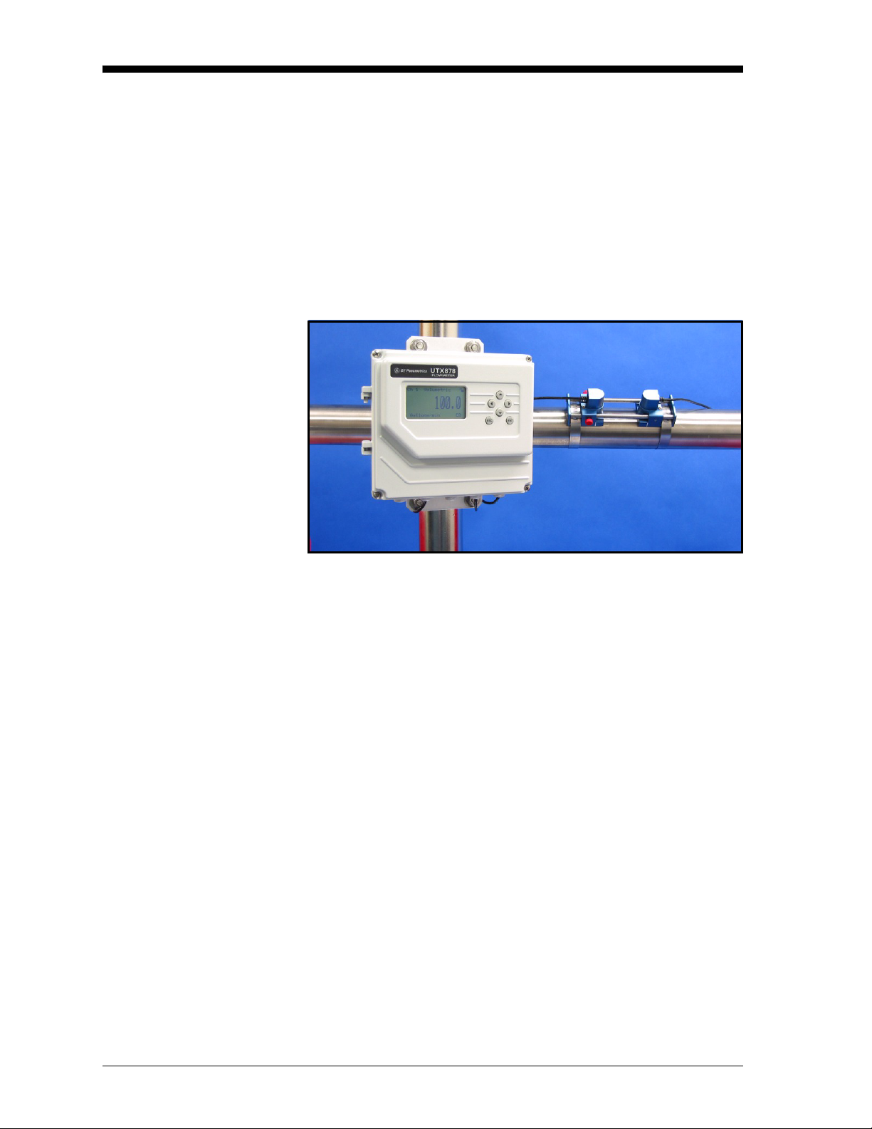
Electronics Enclosure Location
Figure 1: UTX878 Enclosure in Typical Installation
The standard UTX878 electronics enclosure (shown in Figure 1
above) is epoxy-coated aluminum rated for weatherproof NEMA 4X,
IP67 applications. Typically, the enclosure is mounted as close as
possible to the transducers. When choosing a site, make sure the
location permits easy access to the electronics enclosure for
programming, maintenance and service.
2 UTX878 Abridged Manual
Page 8

June 2004
Transducer Location For a given fluid and pipe, the Model UTX878’s accuracy depends
primarily on the location and spacing of the transducers. In addition
to accessibility, when planning for transducer location, adhere to the
following guidelines:
• Locate the transducers so that there are at least 10 pipe diameters
of straight, undisturbed flow upstream and 5 pipe diameters of
straight, undisturbed flow downstream from the measurement
point. Undisturbed flow means avoiding sources of turbulence in
the fluid such as valves, flanges, expansions, and elbows; avoiding
swirl; and avoiding cavitation.
• Locate the transducers on a common axial plane along the pipe.
Locate the transducers on the side of the pipe, rather than the top or
bottom, since the top of the pipe tends to accumulate gas and the
bottom tends to accumulate sediment. Either condition will cause
increased attenuation of the ultrasonic signal. There is no similar
restriction with vertical pipes. However, vertical pipes with
downward flow should be avoided in order to insure a full pipe at
the measurement point.
Cable Lengths Locate the electronics enclosure as close as possible to the
transducers. GE Infrastructure Sensing, Inc. can supply UTX878
transducer cables in fixed lengths from 10 ft (3 m) up to 100 ft (30 m)
in length for remote location of the electronics enclosure.
Transducer Cables When installing the transducer cables, always observe established
standard practices for the installation of electrical cables. Do not route
transducer cables alongside high amperage AC power lines or any
other cables that could cause electrical interference. Also, protect the
transducer cables and connections from the weather and corrosive
atmospheres. Do not run the transducer cables along a pipe with a
surface temperature over 75°C (167°F).
IMPORTANT: Use only the cables and transducers that have been
supplied with the UTX878.
Mounting the UTX878 Electronics Enclosure
The standard Model UTX878 electronics package is housed in a
epoxy-coated aluminum weatherproof NEMA 4X, IP67 enclosure
suitable for indoor or outdoor use. Refer to Chapter 7, Specifications,
of the User’s Manual for the mounting dimensions and the weight of
this enclosure.
UTX878 Abridged Manual 3
Page 9

June 2004
Making the Electrical Connections
Preparing the Unit Before Making Electrical Connections
This section contains instructions for making all the necessary
electrical connections to the Model UTX878 flow transmitter. Refer
to Figure 2 on the next page for a complete wiring diagram.
!ATTENTION EUROPEAN CUSTOMERS!
To meet CE Mark requirements, all cables must be installed
as described in Appendix B, CE Mark Compliance, of the
User’s Manual.
!WARNING!
Always disconnect the line power from the Model UTX878
before removing the front cover.
Prepare the unit as described below before making any electrical
connections.
1. Disconnect any previously wired power line from the unit.
2. Remove the screws on the front cover.
3. Install any required cable clamps on the appropriate conduit holes
on the bottom of the enclosure.
Proceed to the next section to make the desired wiring connections.
4 UTX878 Abridged Manual
Page 10

June 2004
Figure 2: UTX878 Wiring Diagram (Dwg. #702-528_2)
UTX878 Abridged Manual 5
Page 11

June 2004
Wiring the Line Power The Model UTX878 operates on 15-30 VDC loop power. The label
on the side of the electronics enclosure lists the meter’s required line
voltage and power rating. Be sure to connect the meter only to the
specified line voltage and with a shielded cable.
Refer to Figure 2 on the previous page to locate the power terminal
block and connect the line power as follows:
1. Follow the instructions on page 6 to prepare the unit before you
connect power.
2. Connect the UTX878 case to the earth ground with a grounding
cable.
3. Strip 1/4-in. of insulation from the end of each of the two line
power leads.
4. Route the shielded cable through the conduit hole and connect the
power leads to the power terminal block as shown in Figure 2. Tie
the shield drain wire to the ground bus bar inside the UTX878, but
leave the shield wire open on the power supply end
ground loops and for CE certification).
(to avoid AC
5. Leaving a small amount of slack, secure the power line with the
cable clamp.
Note: If you are using a 4-20 mA loop current measuring resistor,
add the resistor in series with the power supply Loop_Rtn end
(TB3-2). You must configure the loop current measuring
equipment as follows:
• The negative side (-) of the probe goes to the power supply
side of the resistor.
• The positive side (+) of the probe goes to the UTX878 side
of the resistor.
6. If you are installing the UTX878 for the first time, replace the
front cover, tighten the screws, and see the next page to unlock
and program the meter and determine the transducer spacing.
6 UTX878 Abridged Manual
Page 12

June 2004
Unlocking and Locking the UTX878
T o prevent unauthorized tampering with either the display or the user
program, the UTX878 offers a pair of security codes. Once you have
set the security level, an operator requires one of these codes to
change either the display (Prog Lock) or the display and the user
program (Full Lock).
Unlocking the UTX878 To unlock the display and/or the user program:
1. Press
[ESC], [ENT], [ESC]. A Security Check window, similar to
Figure 3 below, opens.
Security Check
ENTER VALUE
9999
[ENT] = save changes
[ESC] = undo changes
[W] [X] = move cursor
[S] [T] = change value
Figure 3: Security Check Window
2. Using the arrow keys, change the code number to the value
desired for your security level.
• For Prog Lock (granting access only to the display), the number
2719.
is
• For Full Lock (granting access to the display and user
program), the number is
3. Press [ENT]. The display screen reappears, with the lock removed
or partially unlocked. Security will remain at this level until you
change the level in the user program, as described on the next
page.
7378.
UTX878 Abridged Manual 7
Page 13

June 2004
Locking the UTX878 You can access the security level in two ways.
From the display screen:
1. Press the [X] key three times, until the lock in the upper right
corner is highlighted.
2. Press
From the User Program:
1. Press
2. Press the [X] key until USER is bracketed.
3. The menu highlights Set Security. Press
4. The screen shows three options:
[ENT], and proceed to step 4 below.
[ESC]. The UTX878 stops displaying data and enters the User
Program.
[ENT].
• Full Lock, which prevents a user from changing any part of the
display or user program without the appropriate code:
• Prog Lock, which allows a user to change the display but not to
enter the user program:
• Unlocked, which allows access to both the display and the user
program.
Scroll to the desired option and press
5. Press
[ESC] to return to the User Program, or continue pressing
[ESC] to return to the display screen. If you have chosen to fully
lock the UTX878, the screen appears similar to Figure 4 below,
with a solid lock in the upper right corner. (For a meter with only
the user program locked, the lock shows a keyhole in the center.)
[ENT] twice.
Ch 1 Velocity
0.0
Meters/sec E1
Figure 4: UTX878 Screen with Locked Program
8 UTX878 Abridged Manual
Page 14

June 2004
Programming the UTX878
Activating a Channel/Path (Status)
Before you install the transducers, you must program the UTX878 to
determine appropriate transducer spacing. The meter requires data in
five submenus: Status, Transducer, Pipe, Fluid and Path. (For
information on the other submenus, refer to the UTX878 User’s
Manual.)
In the Status submenu of the PROG menu, you can activate or
deactivate a channel/path. While the channel/path should be activated
when you receive your unit, you should verify that the channel/path is
active before you begin programming.
To access the Status submenu:
1. Press
2. Press the [X] key until
[ESC]. The UTX878 enters the User Program.
PROG is bracketed in the top left corner and
[ENT].
press
3. Use the [S] and [T] keys to scroll to the desired channel or to
2-path Averaging and press
[ENT]. The screen appears similar to
Figure 5 below.
Note: For information on the 2-Path Avg option, see the User’s
Manual.
PROG PROG/PROG
Status . . .
Transducer . . .
Pipe . . .
Fluid . . .
Path . . .
Signal . . .
T
K Factor . . .
Figure 5: The PROG Menu
4. Press
5. The screen offers two options,
[ENT] to open the Status submenu.
ON and OFF. Use the [S] and [T]
keys to scroll to the desired selection and press
[ENT].
IMPORTANT: On any menu, if you scroll to a differ ent option, press
[ENT] twice to select that option (once to enter and
again to confirm the selection).
6. Press
[ESC] (or [ENT] twice if you have selected the other option) to
return to the channel menu.
UTX878 Abridged Manual 9
Page 15

June 2004
Entering Transducer Parameters
The Transducer submenu enables you to enter parameters for
preprogrammed or special clamp-on transducers. Remember to
record all programmed data in Appendix C, Data Records, of the
User’s Manual.
Note: If you have programmed the Status submenu, proceed directly
to Step 4.
To access the Transducer submenu:
1. Press
2. Press the [X] key until
[ESC]. The UTX878 enters the User Program.
PROG is bracketed in the top left corner and
[ENT].
press
3. Use the [S] and [T] keys to scroll to the desired Channel and
[ENT].
press
4. Scroll to the Transducer submenu and press
5. Scroll to Clamp-on and press
[ENT].
[ENT].
6. Scroll to either Preprogrammed (for the standard transducers) or
Other (for special transducers), and press
[ENT].
7. The program also asks for the Wedge Temperature. Scroll to the
Wedge TMP option and press
keys to enter the temperature, and press
[ENT]. Then use the [S] and [T]
[ENT].
Note: The wedge temperature of the transducer can be
approximated by inputting an average value for the surface
temperature of the outside pipe wall.
8. Do one of the following:
• For preprogrammed transducers, scroll to the desired
Transducer Number (either UTXDR-407 (2 MHz) or UTXDR408 (4 MHz) ) and press
return to the
PROG menu.
[ENT]. Then press [ESC] three times to
• For other transducers, refer to the User’s Manual.
IMPORTANT: Other (special) transducers have no engraved
number on the housing and are rarely used. Examine
the transducer housing carefully for a number.
10 UTX878 Abridged Manual
Page 16

June 2004
Entering Pipe Parameters
In the Pipe submenu, you can specify preprogrammed or special pipe
parameters. Remember to record all programmed data in Appendix C,
Data Records, of the User’s Manual. In the
Pipe submenu and press
[ENT].
PROG menu, scroll to the
Entering the Pipe Material 1. The menu offers two options, Material and Lining. Be sure the
Material option is highlighted, and press
2. Two other options now appear, Preprogrammed and Other. Scroll
to the desired option, and press
[ENT].
3. The menu now varies with your choice in Step 2.
[ENT].
• For preprogrammed materials, a list of materials opens. Table 1
below covers the available preprogrammed materials on the list.
Press the [
Press
T] or [S] keys to scroll to the appropriate material.
[ENT] to confirm the choice.
• For other materials, the meter asks for the material Soundspeed.
[ENT] to open the window. Then use the arrow keys to enter
Press
the known soundspeed, and press
.
Table 1: Preprogrammed Pipe Materials
Pipe Material Category Specific Material
Al - Aluminum Rolled or None
Brass None
[ENT].
Cu - Copper Annealed, Rolled or None
CuNi - Copper/Nickel 70% Cu 30% Ni or 90% Cu 10% Ni
Glass Pyrex, Flint, or Crown
Gold Hard-drawn
Inconel None
Iron Armco, Ductile, Cast, Electrolytic
Monel None
Nickel None
Plastic Nylon, Polyethylene, Polyproplene,
PVC (CPVC), or Acrylic
Steel Carbon Steel, Mild or Stainless Steel
Tin Rolled
Titanium None
Tungsten Annealed, Carbide, Drawn
Zinc Rolled
UTX878 Abridged Manual 11
Page 17

June 2004
Entering the Pipe Material
(cont.)
4. The next required parameter is either the outside diameter (OD) or
the circumference (OD x
[ENT]. For either measurement, enter the desired value and
press
[ENT].
press
π). Scroll to the measured parameter and
Note: Obtain the required information by measuring either the pipe
outside diameter (OD) or circumference at the transducer
installation site. The data may also be obtained fr om standard
pipe size tables found in Sound Speeds and Pipe Size Data
(914-004).
5. The meter also requires the Wall Thickness (WT). Scroll to the WT
option, and press
thickness, and press
[ENT]. Use the arrow keys to enter the known
[ENT].
Note: To obtain an accurate pipe wall thickness measurement, use
an ultrasonic thickness gauge.
6. If you have selected certain materials (such as carbon or stainless
steel, cast iron, PVC and CPVC), the UTX878 offers the option of
entering the pipe dimensions by a standardized schedule. (This
option does not appear unless you have selected one of these
materials; if you have, proceed to step a below.) Once you enter
the nominal pipe size and schedule number, the UTX878
determines the OD and wall thickness from an internal table.
a. Scroll to the Schedule option, and press
[ENT].
b. A list of pipe sizes opens, from 15 to 200 mm (0.5 to 8 in.).
Scroll to the desired pipe size, and press
[ENT].
c. A list of schedules opens. Scroll to the desired schedule, and
[ENT].
press
You ha ve finished entering the pipe parameters. Press
[ESC] until you
return to the Pipe Material/Lining window.
12 UTX878 Abridged Manual
Page 18

Entering Pipe Lining Data To access the Lining option:
1. From the Pipe submenu, scroll to the Lining option, and press
[ENT].
2. Two options appear, Material and Thickness. Be sure Material is
highlighted, and press
[ENT].
3. Two other options now appear, Preprogrammed and Other. Scroll
to the desired option, and press
4. The menu now varies with your choice in Step 3.
• For preprogrammed linings, the screen shows a list of Lining
Materials, listed in Table 2 below. Scroll to the appropriate
material. If the pipe has no lining, select None. Press
confirm the choice.
• For other materials, the next screen asks for the lining
Soundspeed. Press
the arrow keys to enter the known soundspeed, and press
[ENT] to open the soundspeed window. Use
June 2004
[ENT].
[ENT] to
[ENT].
Table 2: Preprogrammed Lining Materials
Lining Material Options
None
Tar/Epoxy
Glass (Pyrex)
Asbestos Cement
Mortar
Rubber
Teflon
Note: If your pipe lining is not on the drop-down list, consult GE
Infrastructure Sensing, Inc. for further information.
5. The meter also requires the Lining Thickness. Return to the Lining
screen, scroll to the Thickness option, and press
arrow keys to enter the known thickness, and press
[ENT]. Use the
[ENT].
UTX878 Abridged Manual 13
Page 19

June 2004
Entering Fluid Data The Fluid submenu allows you to specify the fluid you are measuring,
as well as the Reynolds Correction factor and tracking windows.
Remember to record all programmed data in Appendix C, Data
Records, of the User’s Manual. From the
Fluid submenu and press
[ENT] twice.
PROG menu, scroll to the
Entering Fluid Type 1. Two options appear, Fluid Type and Reynolds. Scroll to Fluid
Type and press
2. Two other options appear, Normal and Tracking. Tracking refers
to Tracking Windows, which are used to detect the receive signal
when you are unsure of the fluid sound speed, or when the fluid
sound speed changes drastically under process conditions. Scroll
to the desired option and press
3. You can now select between Preprogrammed and Other fluids.
Scroll to the desired option, and press
[ENT].
[ENT].
[ENT].
• For Normal fluids, you can program the expected fluid
Temperature. Scroll to the Temperature option and press
Then use the arrow keys to enter the process temperature, and
[ENT].
press
[ENT].
• For fluids monitored with a T r acking Window, the meter offers
the selections of Water (up to either 100 or 260°C) or Oil.
Scroll to the desired listing and press
[ENT].
4. The menu now varies, depending on your selections in steps
2 and 3.
• If you have selected Preprogrammed fluids, the UTX878
supplies a list of preprogrammed fluids. As shown in Table 3
on the next page, the list varies, depending on whether you have
selected normal or tracking window fluid types. In either case,
scroll to the desired fluid and press
[ENT].
• If you selected Other, the UTX878 asks for the fluid
soundspeed (for Normal fluids) or minimum and maximum
soundspeed (for Tracking Window fluids). In either case, scroll
to the soundspeed option and press
enter the appropriate soundspeed, and press
5. Press the
[ESC] key until you return to the Fluid Type window.
[ENT]. Use the arrow keys to
[ENT].
14 UTX878 Abridged Manual
Page 20

June 2004
Entering Fluid Data
(cont.)
Entering Reynolds Correction Data
Table 3: Preprogrammed Fluid Types
Tracking Windows Off Tracking Windows On
Water (0-260°C) Water (0-100°C)
Sea Water Water (0-260°C)
Oil (22°C) Oil
Crude Oil
Lube Oil (X200)
Methanol (20°C)
Ethanol
LN2 (-199°C)
Freon (R-12)
Diesel
Gasoline
Reynolds Correction is a correction factor based on the Kinematic
Viscosity and flow rate of the fluid. It is necessary, as the velocity of
the fluid measured along a diametrical path must be related to the
total area average velocity over the entire pipe cross-section. This
factor should be
clamp-on transducers. To access Reynolds Correction data:
ON in most applications, including all those that use
1. From the Fluid Type window, scroll to Reynolds and press
2. The screen shows three options: Off, Single and Table. Scroll to
the desired option, and press
3. The menu varies, depending on your selection in Step 2.
[ENT].
[ENT].
• If you select Off, no further choices are available.
• If you select Single, the UTX878 will select and automatically
display the Kinematic Viscosity. To change the value, press
[ENT]. Use the arrow keys to change the value (available in
document #914-004, Sound Speeds and Pipe Size Data), and
[ENT].
press
UTX878 Abridged Manual 15
Page 21

June 2004
Entering Reynolds
Correction Data (cont.)
• If you select Table, the screen displays three options: Units, Rows
Used and Edit Table.
a. If you scroll to Units and press
more options: Velocity, Soundspeed and Diagnostic. If you
select either Velocity or Soundspeed and press
displays the measurement units (either metric or English).
[ESC] or [ENT] to return to the previous screen. But if you
Press
scroll to Diagnostic and press
of signal to be used, Signal Strength Up or Signal Strength Dn.
Scroll to the appropriate signal, and press
b. If you select Rows Used, the program asks for the number of
rows you wish to use. Enter the desired number (from 2 to 20)
and press
[ENT].
c. If you select Edit Table, the table opens with a series of rows.
Scroll to the desired row, and press
d. For each row, the screen displays the Reynolds Correction
number (X) and the Kinematic Viscosity (KV). If you wish to
change either value, scroll to the value and press
arrow keys to change the value (available in document #914004, Sound Speeds and Pipe Size Data), and press
[ENT], the screen displays three
[ENT], the screen
[ENT], the meter asks for the type
[ENT].
[ENT].
[ENT]. Use the
[ENT].
e. Repeat steps c and d until you have programmed all of your
available data (from 2 to 20 rows).
[ESC] until you return to the PROG menu, or continue pressing
Press
[ESC] until the display screen reappears.
16 UTX878 Abridged Manual
Page 22

June 2004
Entering Path Data In the Path submenu, you can specify and check the path taken by the
transducer signal. Remember to record all programmed data in
Appendix C, Data Records, of the User’s Manual. From the
menu, scroll to the Path submenu and press
[ENT].
1. The meter first asks for the number of Traverses, or times the
signal crosses the pipe. Press
traverses for your installation, and press
[ENT], scroll to the number of
[ENT] to confirm the entry.
Note: The great majority of UTX878 applications call for two
traverses. Figure 6 below illustrates signal paths for a typical
two-traverse installation.
PROG
Figure 6: Signal Paths for a Two-Traverse Installation
2. The remaining prompt displays the Transducer Spacing, as
calculated from the information entered. Use this number to set
the spacing of the transducers (the minimum spacing is 0.9 in.). If
necessary, you can overwrite the spacing to match the actual
physical spacing of the transducers. Press
[ENT] to open the
Spacing window, and use the arrow keys to change the value.
Then press
[ENT] to confirm the value.
IMPORTANT: It is recommended that you do not use a spacing
other than the one calculated by the UTX878.
However, if you do us e a different spacing, do not
change the spacing by more than ±10% from that
calculated by the UTX878.
[ESC] until you return to the PROG menu, or continue pressing
Press
[ESC] until the display screen reappears.
UTX878 Abridged Manual 17
Page 23

June 2004
Installing the Transducers
Setting Transducer Spacing
The transducers that have been specially designed for use with the
UTX878 are available in two models: 4 MHz for 1/2 to 2 in. pipes and
2 MHz for 2 to 8 in., and typically support 2-traverse applications.
The preattached cables come in lengths from 6 to 100 ft. (figure 7
below shows a typical UTX878 transducer).
Adjustment
Screws
Figure 7: UTX878 Transducer/Cable Assembly
To set the desired transducer spacing:
1. Loosen the red screws on the adjustable transducer (shown in
Figure 7 above).
2. Slide the adjustable transducer on the rails until you have
positioned it at the desired spacing. The physical spacing of the
transducers must match the Transducer Spacing parameter
calculated in the Path submenu (as discussed on the previous
page). Use the ruler on the rails and the white tick mark on the
transducer housing to assist in setting the correct spacing.
3. Tighten the red screws to secure the transducer to the rails.
Note: If your application requires one or three traverses, you can
remove the adjustable transducer fr om the rails and use it as a
separate transducer at a 180° angle from the stationary
transducer, as shown in Figure 8 below.
Figure 8: Positioning for 1- or 3-Traverse Applications
18 UTX878 Abridged Manual
Page 24

June 2004
Installing the Transducers on the Pipe
Note: Some pipe pre paration may be required before securing the
transducers to the pipe. Remove any paint or coating from the
surface in contact with the transducers. A flat, smooth surface
is ideal.
1. Apply the supplied couplant to the transducer faces, as shown in
Figure 9 below.
Figure 9: The Transducer Faces
2. Put the transducer fixture at the desired location on the pipe.
Secure it with the supplied stainless steel clamps. Figure 10 below
illustrates a typical installation.
Note: Installation on the sides (at 3 and 9 o’clock) of the pipe is
ideal. The top of the pipe might contain bubbles, while the
bottom might contain sediment.
Figure 10: A Typical Transducer Installation
Once on the pipe, an internal spring mechanism ensures proper
mechanical pressure by “pressing” the transducer face against the
pipe surface. Refer to the next page to wire the transducer cables to
the UTX878.
UTX878 Abridged Manual 19
Page 25

June 2004
Wiring the Transducers !WARNING!
Always disconnect the line power from the Model UTX878
before removing the front cover. Before connecting the
transducers, discharge any static buildup by shorting the
twisted pairs of the transducer cables to the metal shield
on the cable connector.
1. Disconnect the line power and remove the screws from the front
cover. Refer to the wiring diagram in Figure 2 on page 5 and
connect the transducer cables to the terminal block (TB-1) for
Channel 1. Then, secure the cable clamp.
Note: The RED cable leads are the SIG (+) leads and the BLACK
cable leads are the RTN (-) leads. The shield cable leads are
connected to the ground bus.
!ATTENTION EUROPEAN CUSTOMERS!
To meet CE Mark requirements, all cables must be installed
as described in Appendix B, CE Mark Compliance, of the
User’s Manual.
2. For a 2-path averaging UTX878, repeat step 1 to connect the CH2
transducers to the terminal block for Channel 2. It is not
that both channels/paths of a 2-Channel unit be connected.
Note: The UTX878 uses two channels or paths to make more
accurate flow measurement by averaging, subtracting or
adding the channels/paths together. Disabling a channel will
increase the meter response time.
3. Connect the transducer shield wires to the UTX878 ground bus.
4. Do one of the following:
required
• To wire the UTX878 RS232 serial port, refer to the User’s
Manual.
• If you have completed installation, replace the front cover on
the enclosure, tighten the screws and reconnect line power.
The UTX878 is now ready for operation.
20 UTX878 Abridged Manual
Page 26

June 2004
Adjusting the 4-20 mA Loop
To ensure proper operation of the UTX878, you must enter the
CONFIG menu and set the global parameters for your individual
requirements. The available parameters include:
• Metric or English units
• 4-20 Loop Settings (low and high values)
To enter the
enter the User Program) and press the [X] key once.
Entering Global Units In the Units submenu, you can choose to display all measurements in
either metric or English formats.
Note: You cannot choose to display some measurements in English
To access the Units submenu:
1. Press
2. Press the [X] key until
3. Press
CONFIG menu from the display screen, press [ESC] (to
formats and others in metric.
[ESC]. The UTX878 enters the User Program.
CONFIG is bracketed and press [ENT].
[ENT] to enter the Units submenu.
4. Use the [S] and [T] keys to scroll to the desired selection (metric
or English) and press
[ENT]. The UTX878 returns to the CONFIG
menu.
IMPORTANT: In any menu, if you scroll to a different option, press
[ENT] twice to select that option (once to enter and
again to confirm the selection).
UTX878 Abridged Manual 21
Page 27

June 2004
Entering Base (Zero) and Span Output Values
Entering Output Type and Units
The 4-20 Loop submenu enables you to enter the information needed
to set up output parameters: unit type, base (zero) and span values,
and error handling. To enter data in the 4-20 Loop submenu:
1. Press
2. Press the [X] key until
3. Press [T] to reach the 4-20 Loop submenu, and press
[ESC]. The UTX878 enters the User Program.
CONFIG is bracketed and press [ENT].
[ENT].
1. In the Loop submenu, press [ENT] to enter the Units option.
2. The menu displays five options:
DIFF. Use the [S] and [T] keys to scroll to the desired option,
and
and press
Note:
[ENT].
Channel 2, AVG, SUM and DIFF are only available for a
Channel 1, Channel 2, AVG, SUM
2-Channel UTX878.
3. The screen now displays three measurement parameters: velocity,
volumetric, and soundspeed. Scroll to the desired selection and
[ENT].
press
4. The menu now asks for the unit type.
• For velocity or soundspeed measurements, the menu offers a
single selection (either feet/sec or meters/sec, depending on
your choice of units). Press
return to the previous menu.
[ENT] to confirm the entry and
• For volumetric measurements, the menu offers a list of output
units (either metric or English). Scroll to the desired units and
press
[ENT].
[ESC] until you return to the CONFIG menu.
Press
22 UTX878 Abridged Manual
Page 28

June 2004
Entering Base and Span Values
Trimming 4-20 mA Values via the Keypad
1. In the Loop option, press [T] and [ENT] to enter the Base option.
2. The Base window opens. Use the arrow keys to enter the desired
base (4 mA) value for the analog output, and press
3. The UTX878 returns to the Loop menu. Press [T] and
[ENT].
[ENT] to
enter the Span option.
4. The Span window opens. Use the arrow keys to enter the desired
span (20 mA) value for the analog output, and press
[ENT].
1. In the User Program, press the [X] key until CAL is bracketed,
with 4-20 Loop highlighted. Press
2. Scroll to Mode and press
Test[Trim] and press
[ENT]. In the Mode window, scroll to
[ENT].
[ENT].
3. Return to the Loop window, and scroll to Percent.
4. In the Percent window , use the arrow keys to set the percentage to
100%. Press
5. Now use the arrow keys to set the percentage to 0%. Press
[ENT]. Record the value shown on the ammeter.
[ENT].
Record the value shown on the ammeter.
6. Return to the Loop window, and scroll to Base Trim. Press
[ENT].
7. Use the arrow keys to enter the base trim value, the value recorded
in step 5. (The loop current should now be the same as the
ammeter reading). It should read 4.0 +/-0.01 mA.) Press
[ENT].
8. Repeat steps 3 and 4.
9. Return to the Loop window, and scroll to Span Trim. Press
[ENT].
10.Use the arrow keys to enter the span trim value, the value recorded
in step 4. (The loop current should now be the same as the
ammeter reading. It should read 20.0 +/-0.01 mA.) Press
11.Return to the Loop window , and scroll to Mode. Press
to Normal, and press
[ENT].
[ENT].
[ENT]. Scroll
UTX878 Abridged Manual 23
Page 29

GE Industrial
Sensing
We, Panametrics Limited
Shannon Industrial Estate
Shannon, County Clare
Ireland
declare under our sole responsibility that the
UTX878 Ultrasonic Flowmeter
including UTXDR-407 & UTXDR-408 Flow Transducers
to which this declaration relates, are in conformity with the following standards:
• EN 61326:1998, Class A, Annex A, Continuous Unmonitored Operation
following the provisions of the 89/336/EEC EMC Directive.
DECLARATION
OF
CONFORMITY
Shannon - April 9, 2004
Mr. James Gibson
GENERAL MANAGER
TÜV
TÜV ESSEN
ISO 9001
U.S.
CERT-DOC-H0 August 2004
Page 30

USA
1100 Technology Park Drive
Billerica, MA 01821-4111
Web: www.geSensing, Inc..com
Ireland
Shannon Industrial Estate
Shannon, County Clare
Ireland
 Loading...