

Page 1
dew.IQ
Moisture Analyzer
User’s Manual
Moisture
bhge.com
910-295 Rev. C
October 2017
Page 2

Page 3

dew.IQ
Moisture Analyzer
User’s Manual
910-295 Rev. C
October 2017
bhge.com
© 2017 Baker Hughes, a GE company – All rights reserved.
Baker Hughes reserves the right to make changes in specifications and features shown
herein, or discontinue the product described at any time without notice or obligation.
Contact your BHGE representative for the most current information. The Baker Hughes
logo is a trade mark of Baker Hughes, a GE company. The GE Monogram is a trademark of
the General Electric Company.
Page 4

[no content intended for this page]
ii dew.IQ User’s Manual
Page 5

Contents
Chapter 1. Features and Capabilities
1.1 Introduction . . . . . . . . . . . . . . . . . . . . . . . . . . . . . . . . . . . . . . . . . . . . . . . . . . . . . . . . . . . .1
1.2 Electronics. . . . . . . . . . . . . . . . . . . . . . . . . . . . . . . . . . . . . . . . . . . . . . . . . . . . . . . . . . . . . .1
1.3 Probes. . . . . . . . . . . . . . . . . . . . . . . . . . . . . . . . . . . . . . . . . . . . . . . . . . . . . . . . . . . . . . . . . .2
Chapter 2. Installation
2.1 Introduction . . . . . . . . . . . . . . . . . . . . . . . . . . . . . . . . . . . . . . . . . . . . . . . . . . . . . . . . . . . .3
2.2 Selecting the Analog Recorder Output. . . . . . . . . . . . . . . . . . . . . . . . . . . . . . . . . . .4
2.3 Mounting the Electronics. . . . . . . . . . . . . . . . . . . . . . . . . . . . . . . . . . . . . . . . . . . . . . . .8
2.3.1 Panel Mount . . . . . . . . . . . . . . . . . . . . . . . . . . . . . . . . . . . . . . . . . . . . . . . . . . .8
2.3.2 Rack Mount . . . . . . . . . . . . . . . . . . . . . . . . . . . . . . . . . . . . . . . . . . . . . . . . . . 12
2.3.3 Bench Mount. . . . . . . . . . . . . . . . . . . . . . . . . . . . . . . . . . . . . . . . . . . . . . . . . 13
2.3.4 Wall Mount . . . . . . . . . . . . . . . . . . . . . . . . . . . . . . . . . . . . . . . . . . . . . . . . . . 14
2.4 Mounting the Sample System . . . . . . . . . . . . . . . . . . . . . . . . . . . . . . . . . . . . . . . . . 15
2.5 Installing the Probe . . . . . . . . . . . . . . . . . . . . . . . . . . . . . . . . . . . . . . . . . . . . . . . . . . . 16
2.6 Wiring the System . . . . . . . . . . . . . . . . . . . . . . . . . . . . . . . . . . . . . . . . . . . . . . . . . . . . 18
2.6.1 Connecting an M Series Probe . . . . . . . . . . . . . . . . . . . . . . . . . . . . . . . . 21
2.6.2 Connecting an IQ.probe . . . . . . . . . . . . . . . . . . . . . . . . . . . . . . . . . . . . . . 24
2.6.3 Connecting the Analog Output . . . . . . . . . . . . . . . . . . . . . . . . . . . . . . . 27
2.6.4 Connecting the Alarm Relays . . . . . . . . . . . . . . . . . . . . . . . . . . . . . . . . . 27
2.6.5 Connecting the Input Power . . . . . . . . . . . . . . . . . . . . . . . . . . . . . . . . . . 30
Chapter 3. Initial Setup & Operation
3.1 Using the dew.IQ. . . . . . . . . . . . . . . . . . . . . . . . . . . . . . . . . . . . . . . . . . . . . . . . . . . . . . 35
3.1.1 Starting Up. . . . . . . . . . . . . . . . . . . . . . . . . . . . . . . . . . . . . . . . . . . . . . . . . . . 36
3.1.2 Accessing the Menus . . . . . . . . . . . . . . . . . . . . . . . . . . . . . . . . . . . . . . . . . 36
3.1.3 Entering Numeric Values . . . . . . . . . . . . . . . . . . . . . . . . . . . . . . . . . . . . . 37
3.2 Setting Up the Display . . . . . . . . . . . . . . . . . . . . . . . . . . . . . . . . . . . . . . . . . . . . . . . . 38
3.2.1 Selecting the Primary Units. . . . . . . . . . . . . . . . . . . . . . . . . . . . . . . . . . . 38
3.2.2 Setting the Decimal Places . . . . . . . . . . . . . . . . . . . . . . . . . . . . . . . . . . . 39
3.2.3 Adjusting the Contrast . . . . . . . . . . . . . . . . . . . . . . . . . . . . . . . . . . . . . . . 39
3.3 Setting Up the Analog Output . . . . . . . . . . . . . . . . . . . . . . . . . . . . . . . . . . . . . . . . . 40
3.3.1 Entering the Output Menu. . . . . . . . . . . . . . . . . . . . . . . . . . . . . . . . . . . . 40
3.3.2 Selecting the Output Units . . . . . . . . . . . . . . . . . . . . . . . . . . . . . . . . . . . 40
3.3.3 Selecting an Output Type. . . . . . . . . . . . . . . . . . . . . . . . . . . . . . . . . . . . . 41
3.3.4 Changing the Output Span . . . . . . . . . . . . . . . . . . . . . . . . . . . . . . . . . . . 41
3.3.5 Changing the Output Zero . . . . . . . . . . . . . . . . . . . . . . . . . . . . . . . . . . . . 42
3.3.6 Testing the Output . . . . . . . . . . . . . . . . . . . . . . . . . . . . . . . . . . . . . . . . . . . 43
dew.IQ User’s Manual iii
Page 6

Contents
3.3.7 Trimming the Output . . . . . . . . . . . . . . . . . . . . . . . . . . . . . . . . . . . . . . . . . 44
3.4 Setting Up the Measurement Alarms . . . . . . . . . . . . . . . . . . . . . . . . . . . . . . . . . . 46
3.4.1 Selecting an Alarm Output. . . . . . . . . . . . . . . . . . . . . . . . . . . . . . . . . . . . 46
3.4.2 Selecting the Alarm Status . . . . . . . . . . . . . . . . . . . . . . . . . . . . . . . . . . . 47
3.4.3 Selecting the Alarm Units. . . . . . . . . . . . . . . . . . . . . . . . . . . . . . . . . . . . . 47
3.4.4 Selecting an Alarm Type . . . . . . . . . . . . . . . . . . . . . . . . . . . . . . . . . . . . . . 48
3.4.5 How the Alarm Types Work . . . . . . . . . . . . . . . . . . . . . . . . . . . . . . . . . . . 49
3.4.6 Setting the Alarm Span . . . . . . . . . . . . . . . . . . . . . . . . . . . . . . . . . . . . . . . 50
3.4.7 Setting the Alarm Zero . . . . . . . . . . . . . . . . . . . . . . . . . . . . . . . . . . . . . . . 50
3.4.8 Testing the Alarm Relays . . . . . . . . . . . . . . . . . . . . . . . . . . . . . . . . . . . . . 51
3.5 Viewing System Information . . . . . . . . . . . . . . . . . . . . . . . . . . . . . . . . . . . . . . . . . . 52
3.5.1 Checking the ID . . . . . . . . . . . . . . . . . . . . . . . . . . . . . . . . . . . . . . . . . . . . . . 52
3.5.2 Checking the Status . . . . . . . . . . . . . . . . . . . . . . . . . . . . . . . . . . . . . . . . . . 53
3.5.3 Checking the Software Version . . . . . . . . . . . . . . . . . . . . . . . . . . . . . . . 53
3.5.4 Checking the Probe. . . . . . . . . . . . . . . . . . . . . . . . . . . . . . . . . . . . . . . . . . . 54
3.5.5 Checking the Wiring . . . . . . . . . . . . . . . . . . . . . . . . . . . . . . . . . . . . . . . . . . 55
3.6 Locking the Main Menu. . . . . . . . . . . . . . . . . . . . . . . . . . . . . . . . . . . . . . . . . . . . . . . . 55
Chapter 4. Data Logging
4.1 Checking the Data Log Status . . . . . . . . . . . . . . . . . . . . . . . . . . . . . . . . . . . . . . . . . 57
4.2 The Log Settings Menu . . . . . . . . . . . . . . . . . . . . . . . . . . . . . . . . . . . . . . . . . . . . . . . . 57
4.3 Setting the Log Units . . . . . . . . . . . . . . . . . . . . . . . . . . . . . . . . . . . . . . . . . . . . . . . . . . 57
4.4 Setting the Log Interval . . . . . . . . . . . . . . . . . . . . . . . . . . . . . . . . . . . . . . . . . . . . . . . 59
4.5 Setting a Log Field Separator . . . . . . . . . . . . . . . . . . . . . . . . . . . . . . . . . . . . . . . . . . 59
4.6 Setting the Log Status Flags . . . . . . . . . . . . . . . . . . . . . . . . . . . . . . . . . . . . . . . . . . . 60
4.7 Managing Log Files . . . . . . . . . . . . . . . . . . . . . . . . . . . . . . . . . . . . . . . . . . . . . . . . . . . . 61
4.7.1 Creating a New Log. . . . . . . . . . . . . . . . . . . . . . . . . . . . . . . . . . . . . . . . . . . 61
4.7.2 Pausing or Closing a Log . . . . . . . . . . . . . . . . . . . . . . . . . . . . . . . . . . . . . . 62
4.7.3 Resuming a Log . . . . . . . . . . . . . . . . . . . . . . . . . . . . . . . . . . . . . . . . . . . . . . 63
4.7.4 Viewing the Log Directory . . . . . . . . . . . . . . . . . . . . . . . . . . . . . . . . . . . . 63
4.7.5 Deleting Log Files. . . . . . . . . . . . . . . . . . . . . . . . . . . . . . . . . . . . . . . . . . . . . 64
4.8 Ejecting the MicroSD Card. . . . . . . . . . . . . . . . . . . . . . . . . . . . . . . . . . . . . . . . . . . . . 65
4.9 Viewing Data Log Files . . . . . . . . . . . . . . . . . . . . . . . . . . . . . . . . . . . . . . . . . . . . . . . . 66
Chapter 5. Programming the Settings Menu
5.1 Entering Your Passcode . . . . . . . . . . . . . . . . . . . . . . . . . . . . . . . . . . . . . . . . . . . . . . . 67
5.2 Setting the Fault Alarm. . . . . . . . . . . . . . . . . . . . . . . . . . . . . . . . . . . . . . . . . . . . . . . . 68
5.2.1 Setting the Fault Alarm Status. . . . . . . . . . . . . . . . . . . . . . . . . . . . . . . . 68
iv dew.IQ User’s Manual
Page 7

Contents
5.2.2 Setting the Fault Alarm Type. . . . . . . . . . . . . . . . . . . . . . . . . . . . . . . . . . 69
5.2.3 Setting the Fault Alarm Options . . . . . . . . . . . . . . . . . . . . . . . . . . . . . . 69
5.2.4 Testing the Fault Alarm. . . . . . . . . . . . . . . . . . . . . . . . . . . . . . . . . . . . . . . 70
5.3 Setting AutoCal . . . . . . . . . . . . . . . . . . . . . . . . . . . . . . . . . . . . . . . . . . . . . . . . . . . . . . . 70
5.4 Entering Calibration Data for an M Series Probe . . . . . . . . . . . . . . . . . . . . . . . 72
5.4.1 Selecting the Number of Points. . . . . . . . . . . . . . . . . . . . . . . . . . . . . . . 72
5.4.2 Selecting the Calibration Point . . . . . . . . . . . . . . . . . . . . . . . . . . . . . . . 73
5.4.3 Entering the MH Calibration . . . . . . . . . . . . . . . . . . . . . . . . . . . . . . . . . . 73
5.4.4 Entering the Dew Point Calibration . . . . . . . . . . . . . . . . . . . . . . . . . . . 74
5.5 Viewing Calibration Data for an IQ.probe . . . . . . . . . . . . . . . . . . . . . . . . . . . . . . 75
5.5.1 Selecting the Calibration Point . . . . . . . . . . . . . . . . . . . . . . . . . . . . . . . 75
5.5.2 Reading the FH Value. . . . . . . . . . . . . . . . . . . . . . . . . . . . . . . . . . . . . . . . . 76
5.5.3 Reading the DP Value. . . . . . . . . . . . . . . . . . . . . . . . . . . . . . . . . . . . . . . . . 76
5.6 Reading and Setting the Calibration References . . . . . . . . . . . . . . . . . . . . . . . 77
5.6.1 Setting the Calibration High Reference . . . . . . . . . . . . . . . . . . . . . . . 78
5.6.2 Setting the Calibration Low Reference . . . . . . . . . . . . . . . . . . . . . . . . 78
5.7 Entering an M Series Probe Serial Number. . . . . . . . . . . . . . . . . . . . . . . . . . . . . 79
5.8 Setting the Volume Mixing Ratio. . . . . . . . . . . . . . . . . . . . . . . . . . . . . . . . . . . . . . . 80
5.8.1 Setting the Pressure Units. . . . . . . . . . . . . . . . . . . . . . . . . . . . . . . . . . . . 80
5.8.2 Setting the Pressure Value . . . . . . . . . . . . . . . . . . . . . . . . . . . . . . . . . . . 81
5.8.3 Setting the k x PPMv Multiplier . . . . . . . . . . . . . . . . . . . . . . . . . . . . . . . 81
5.9 Setting the System Clock. . . . . . . . . . . . . . . . . . . . . . . . . . . . . . . . . . . . . . . . . . . . . . 82
5.9.1 Setting the Hour . . . . . . . . . . . . . . . . . . . . . . . . . . . . . . . . . . . . . . . . . . . . . 82
5.9.2 Setting the Minutes . . . . . . . . . . . . . . . . . . . . . . . . . . . . . . . . . . . . . . . . . . 83
5.9.3 Setting the Month . . . . . . . . . . . . . . . . . . . . . . . . . . . . . . . . . . . . . . . . . . . . 83
5.9.4 Setting the Date. . . . . . . . . . . . . . . . . . . . . . . . . . . . . . . . . . . . . . . . . . . . . . 84
5.9.5 Setting the Year . . . . . . . . . . . . . . . . . . . . . . . . . . . . . . . . . . . . . . . . . . . . . . 84
5.10 Selecting the Probe Type . . . . . . . . . . . . . . . . . . . . . . . . . . . . . . . . . . . . . . . . . . . . . . 85
5.11 Setting a Constant DP °C Offset . . . . . . . . . . . . . . . . . . . . . . . . . . . . . . . . . . . . . . . 86
Chapter 6. Service and Maintenance
6.1 Introduction . . . . . . . . . . . . . . . . . . . . . . . . . . . . . . . . . . . . . . . . . . . . . . . . . . . . . . . . . . 87
6.2 The Service Menu . . . . . . . . . . . . . . . . . . . . . . . . . . . . . . . . . . . . . . . . . . . . . . . . . . . . . 87
6.3 Troubleshooting Common Problems. . . . . . . . . . . . . . . . . . . . . . . . . . . . . . . . . . . 88
6.4 Replacing/Recalibrating Moisture Probes . . . . . . . . . . . . . . . . . . . . . . . . . . . . . . 89
6.5 Cleaning the dew.IQ Front Panel. . . . . . . . . . . . . . . . . . . . . . . . . . . . . . . . . . . . . . . 90
dew.IQ User’s Manual v
Page 8

Contents
Chapter 7. Specifications
7.1 Electronics. . . . . . . . . . . . . . . . . . . . . . . . . . . . . . . . . . . . . . . . . . . . . . . . . . . . . . . . . . . . 91
7.2 Moisture Measurement . . . . . . . . . . . . . . . . . . . . . . . . . . . . . . . . . . . . . . . . . . . . . . . 93
Appendix A. Outline and Installation Drawings . . . . . . . . . . . . . . . . . . . . . . . . 95
Appendix B. Menu Maps . . . . . . . . . . . . . . . . . . . . . . . . . . . . . . . . . . . . . . . . . . . . . . 103
Appendix C. Reading the MicroSD Card . . . . . . . . . . . . . . . . . . . . . . . . . . . . . . . 107
C.1 Removing the MicroSD Card . . . . . . . . . . . . . . . . . . . . . . . . . . . . . . . . . . . . . . . . . . 107
C.2 Connecting the MicroSD Card to a PC. . . . . . . . . . . . . . . . . . . . . . . . . . . . . . . . . 109
C.3 Accessing the Log Files. . . . . . . . . . . . . . . . . . . . . . . . . . . . . . . . . . . . . . . . . . . . . . . 110
C.4 Setting Up a Log File . . . . . . . . . . . . . . . . . . . . . . . . . . . . . . . . . . . . . . . . . . . . . . . . . 113
Default Factory Passcode . . . . . . . . . . . . . . . . . . . . . . . . . . . . . . . . . . . . . . . . . . . 125
vi dew.IQ User’s Manual
Page 9
Chapter 1. Features and Capabilities
Chapter 1. Features and Capabilities
1.1 Introduction
The dew.IQ is a single-channel hygrometer that measures moisture
content in gases. It is suitable for a wide range of process conditions in
applications that require real-time moisture measurement.
The dew.IQ accepts any calibration range provided with BHGE probes
(see Chapter 7, Specifications for more information). It comes equipped
with two high/low alarm relays, one fault alarm relay, and a single
analog output. It also has on-board data logging capability using a
micro SD card.
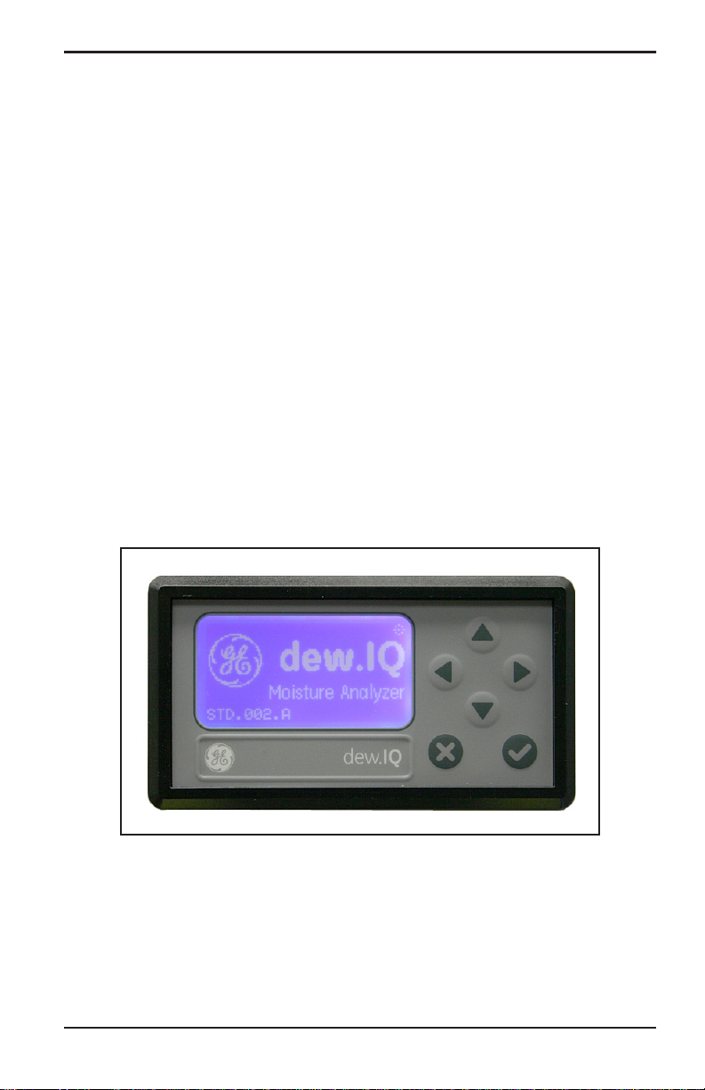
1.2 Electronics
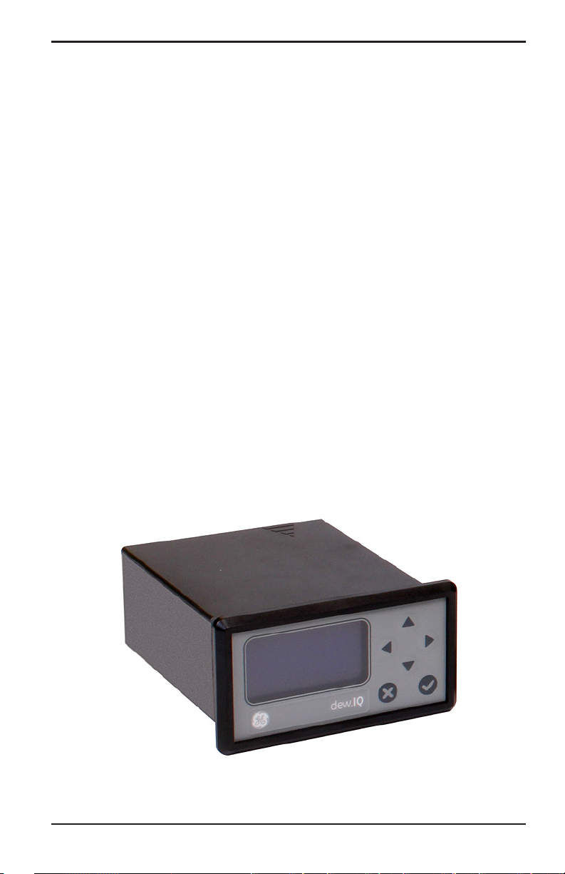
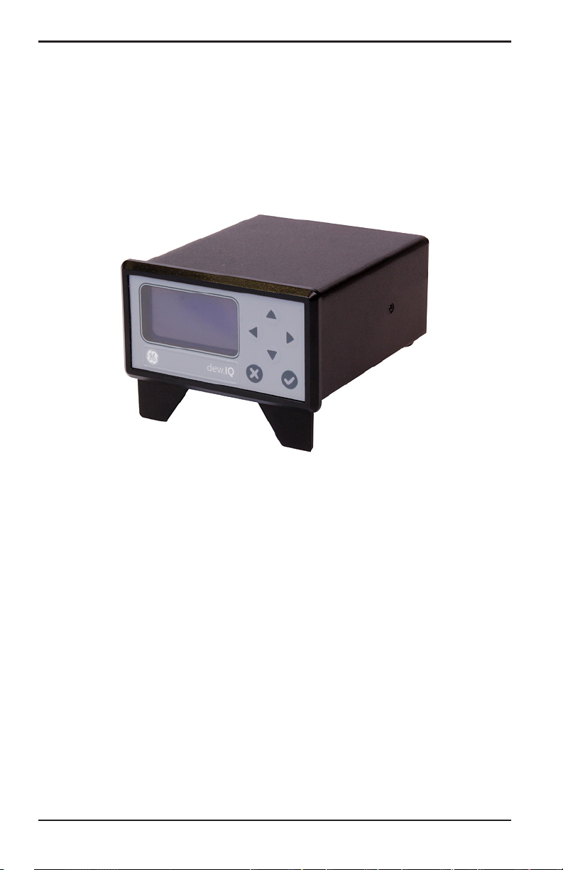
You can program the meter using the keys on the front panel (see
Figure 1 below). The dew.IQ universal power supply accepts voltages
from 100 to 240 VAC, or you may order the 24 VDC configuration.
Figure 1: Front Panel
dew.IQ User’s Manual 1
Page 10
Chapter 1. Features and Capabilities
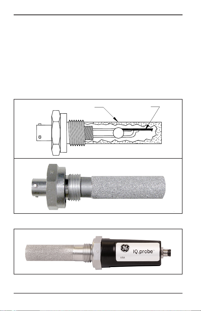
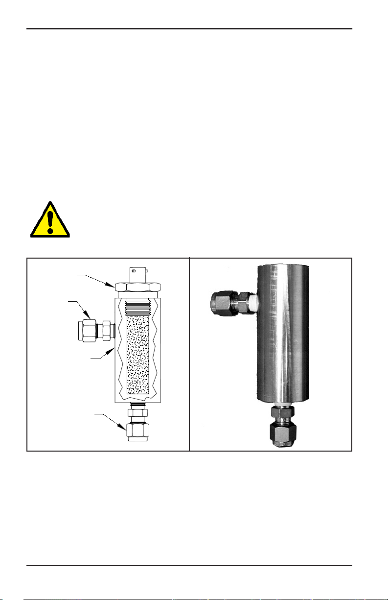
1.3 Probes
The moisture probe is the part of the system that comes in direct
contact with the process. The dew.IQ uses any BHGE M Series probe
(see Figure 2 below) or an IQ.probe (see Figure 3 below) to measure
dew point temperature in °C or °F. The sensor assembly is secured to
the probe mount and is protected with a sintered stainless steel
shield (see Figure 2 below).
Note: Other types of shields are available upon request.
Shield
Figure 2: M Series Probe
Sensor
Figure 3: IQ.probe
2 dew.IQ User’s Manual
Page 11

Chapter 2. Installation
2.1 Introduction
Installing the dew.IQ includes the following steps:
• Selecting the analog recorder output (see page 4)
• Mounting the electronics (see page 8)
• Mounting the sample system (see page 15)
• Installing the probe (page 16)
• Wiring the system (see page 18)
WARNING! To ensure safe operation, the dew.IQ must be
installed and operated as described in this manual. Also,
be sure to follow all applicable local safety codes and
regulations for installing electrical equipment.
Chapter 2. Installation
dew.IQ User’s Manual 3
Page 12
Chapter 2. Installation
2.2 Selecting the Analog Recorder Output
Note: By default, the analog recorder output is set to the current
output.
Note: Customers must provide their own cable for connecting the
analog recorder output. Cables ranging from 16 to 26 AWG are
acceptable.
The dew.IQ has one isolated analog recorder output. The analog
recorder output provides either a current or voltage signal, as
determined by the position of switch S1 on the main PC board.
Complete the following steps to check or reset switch S1 (see Figure 8
on page 7):
WARNING! Never connect line voltage or any other
power input to the analog recorder output terminals.
1. Make sure the
dew.IQ is turned OFF and unplugged. For wall
mount and bench mount units, remove the dew.IQ from its
enclosure before proceeding (see the appropriate figures in
Appendix A).
WARNING! The dew.IQ must be isolated or disconnected
from all voltage sources before changing the recorder
output.
4 dew.IQ User’s Manual
Page 13
Chapter 2. Installation
2.2 Selecting the Analog Recorder Output (cont.)
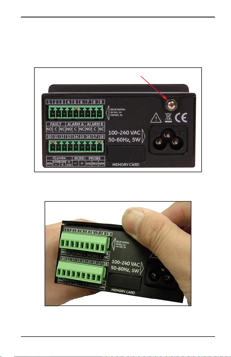
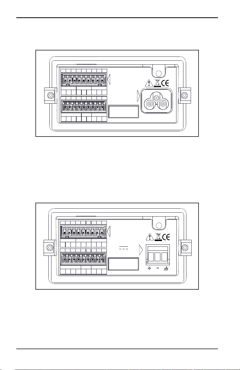
2. Remove the screw at the top of the back panel (see Figure 4
below).
Screw
Figure 4: Back Panel (AC cord version shown)
3. Lift the back edge of the top cover (see Figure 5 below).
Figure 5: Lifting the Back Edge of the Cover
dew.IQ User’s Manual 5
Page 14
Chapter 2. Installation
2.2 Selecting the Analog Recorder Output (cont.)
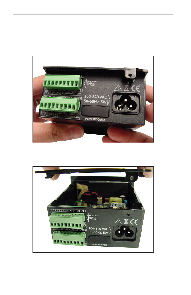
4. Slide the cover toward the back of the dew.IQ (see Figure 6
below).
Figure 6: Sliding the Cover to the Rear
5. Lift the cover away from the enclosure (see Figure 7 below).
Figure 7: Removing the Cover
6 dew.IQ User’s Manual
Page 15

Chapter 2. Installation
dew.IQ User’s Manual 7
Page 16
Chapter 2. Installation
2.2 Selecting the Analog Recorder Output (cont.)
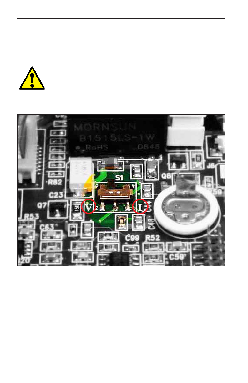
6. Locate switch S1 (see the highlighted area in Figure 8 below).
CAUTION! Use proper ESD grounding prior to setting the
switch.
7. Set switch S1 to the desired position: V for voltage or I for current.
Figure 8: Switch S1 on the Main PC Board
8. After setting the switch, reinstall the cover and secure it with the
rear enclosure screw. For wall mount and bench mount units,
reinstall the dew.IQ in its enclosure (see the appropriate figures in
Appendix A).
8 dew.IQ User’s Manual
Page 17
Chapter 2. Installation
2.3 Mounting the Electronics
The dew.IQ is available in the following configurations:
• “Panel Mount” on page 8
• “Rack Mount” on page 12
• “Bench Mount” on page 13
• “Wall Mount” on page 14
Proceed to the appropriate section for mounting your
electronics.
dew.IQ
2.3.1 Panel Mount
The panel mount unit can be installed in a panel up to 0.25 in. (6 mm)
thick. See Figure 43 on page 100, for the required panel cutout
dimensions.
IMPORTANT: For Type 4X and IP66 installation, the dew.IQ must be
mounted in a rigid, flat panel using the panel gasket and
both mounting brackets provided.
dew.IQ User’s Manual 9
Page 18
Chapter 2. Installation
2.3.1 Panel Mount (cont.)
To mount the dew.IQ in a panel with a 3.69” (94 mm) x 1.81” (46 mm)
opening, refer to the figures and complete the following steps:
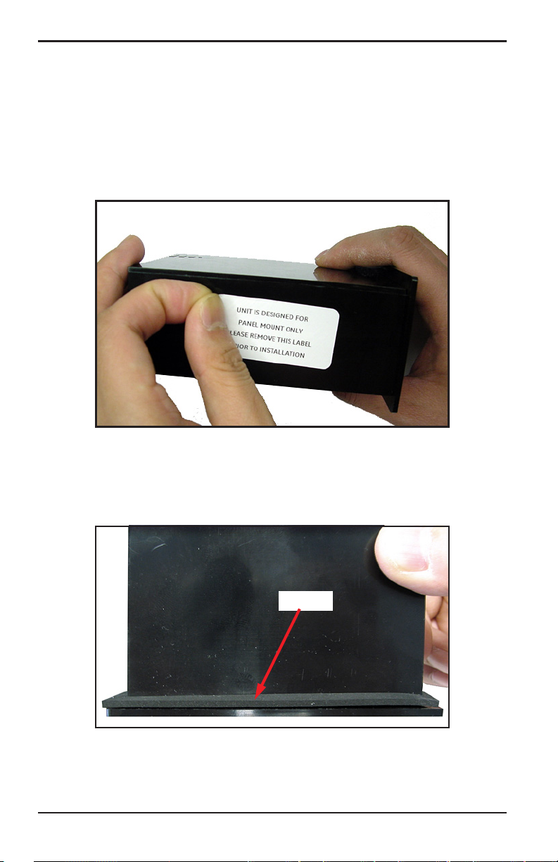
1. Remove the side panel mount label prior to installation.
Figure 9: Removing Side Panel Mount Label
2. Slide the gasket along the
dew.IQ and place it around the back of
the display (see Figure 10 below).
Gasket
Figure 10: Installing the Gasket Behind the Display
10 dew.IQ User’s Manual
Page 19
Chapter 2. Installation
2.3.1 Panel Mount (cont.)
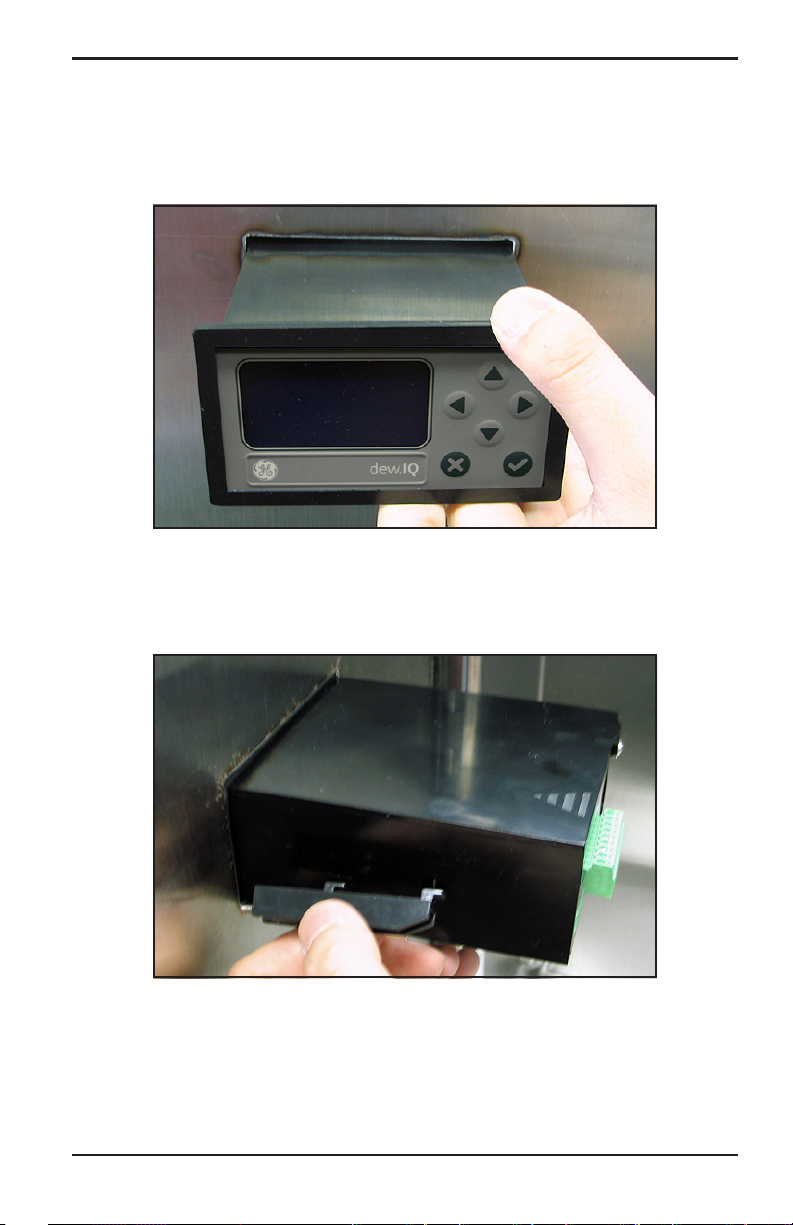
3. Slide the dew.IQ into the panel cutout (see Figure 11 below).
Figure 11: Sliding the dew.IQ into the Panel Cutout
4. Behind the panel, insert the mounting brackets into the side holes
provided (see Figure 12 below).
Figure 12: Installing the Mounting Brackets
dew.IQ User’s Manual 11
Page 20
Chapter 2. Installation
2.3.1 Panel Mount (cont.)
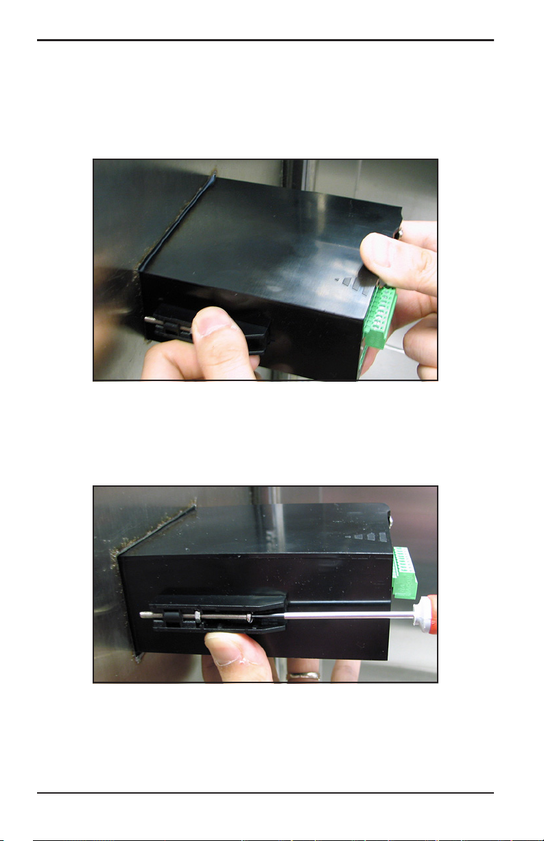
5. Hold the chassis and lock each mounting bracket in place by
sliding it toward the rear of the dew.IQ (see Figure 13 below).
Figure 13: Locking the Mounting Brackets in Place
6. Use a screwdriver to extend the bracket screws to the back of the
panel and secure the
below).
dew.IQ in the panel cutout (see Figure 14
Figure 14: Securing the dew.IQ to the Panel
12 dew.IQ User’s Manual
Page 21
Chapter 2. Installation
2.3.1 Panel Mount (cont.)
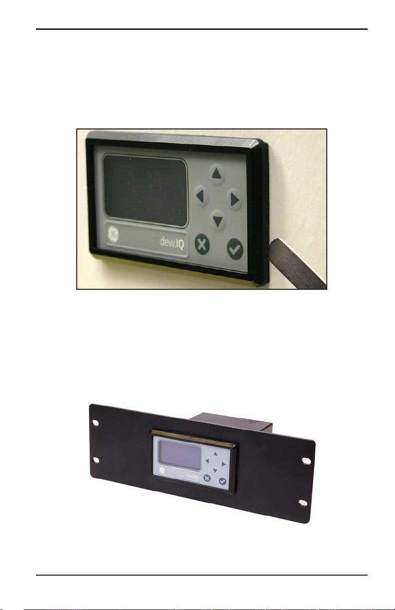
7. Using a feeler gauge behind the display, check the gasket
compression, and tighten the bracket screws until the gap is 0.028”
(0.71 mm) ± 0.002” (0.05 mm), as shown in see Figure 15 below.
Figure 15: Checking the Gasket Compression
2.3.2 Rack Mount
The rack mount dew.IQ is a half-rack sized component designed for
mounting in a standard instrument rack. See Figure 42 on page 99, for
the dimensions.
dew.IQ User’s Manual 13
Page 22
Chapter 2. Installation
2.3.3 Bench Mount
The bench mount dew.IQ can be placed on any clean, flat, horizontal
surface that provides adequate clearance around the unit for proper
operation and configuration. See Figure 44 on page 101, for the
dimensions.
14 dew.IQ User’s Manual
Page 23

Chapter 2. Installation
2.3.4 Wall Mount
The wall mount dew.IQ consists of a panel mount unit pre-installed in
a standard Type 4X, IP66 wall mount enclosure. See Figure 39 on
page 96, Figure 40 on page 97 and Figure 41 on page 98 for dimensions
and installation notes.
The enclosure should be mounted on a vertical surface that provides
adequate clearance for proper operation and configuration by
completing the following steps:
1. Loosen the four (4) screws on the front of the enclosure, pull the
door straight forward until it stops and then swing the door open
(it is hinged on the left side).
2. Install four (4) self-drilling wall anchors in your mounting location
per the hole pattern shown in Figure 39 on page 96.
3. Mount the enclosure on the wall using four (4) #8 x 1-1/2” machine
screws in the four mounting holes provided.
4. Prior to operation, the door must be closed and secured with the
four screws located at the corners.
dew.IQ User’s Manual 15
Page 24
Chapter 2. Installation
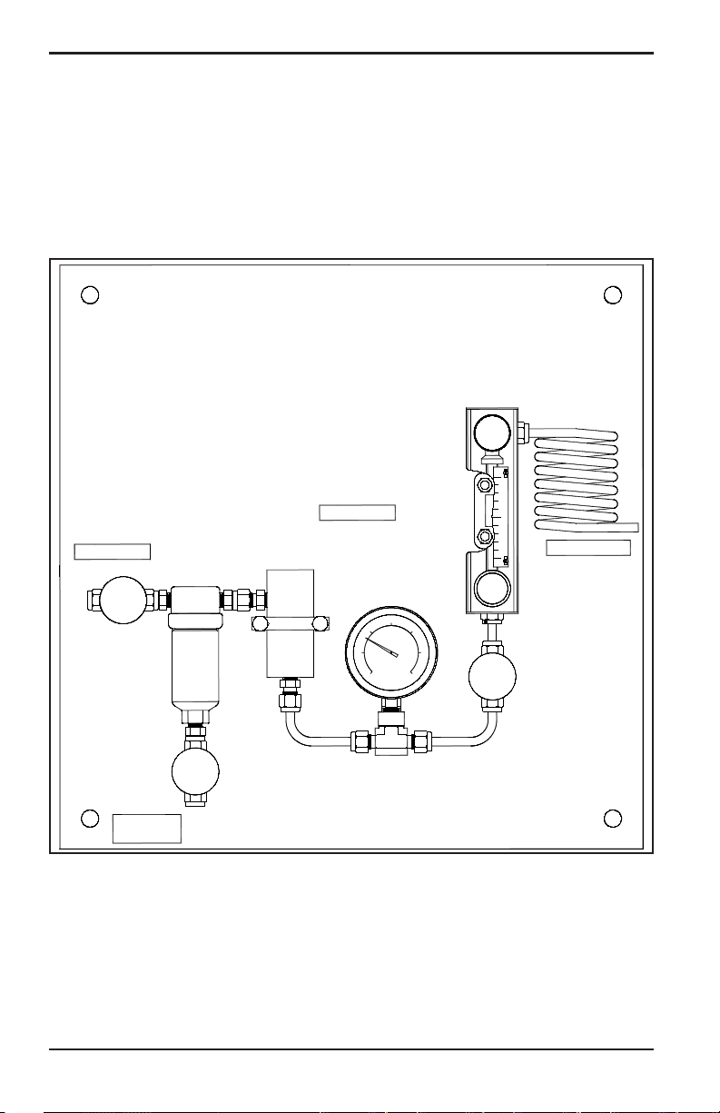
2.4 Mounting the Sample System
The sample system is normally fastened to a flat metal plate that has
four mounting holes. Upon request, BHGE can also provide the sample
system in an enclosure. A typical sample system is shown in
Figure 16 below.
PRESSURE
SAMPLE INLET
SAMPLE
CELL
ASSEMBLY
SAMPLE CELL
PRESSURE
GAUGE
ASSEMBLY
REGULATOR
COOLING
COIL
SAMPLE OUTLET
NEEDLE
VALV E
NEEDLE
VALV E
NEEDLE
VALV E
COALESCER
DRAIN
Figure 16: Typical Sample System
16 dew.IQ User’s Manual
Page 25
Chapter 2. Installation
2.4 Mounting the Sample System (cont.)
Complete the following steps to mount the sample system:
1. Fasten the sample system plate or enclosure to a vertical wall or
panel with a bolt in each of the four corners.
2. Connect the sample system inlet to the process and the outlet to
the return, using appropriate stainless steel fittings and tubing.
CAUTION! Do not start the process flow through the
system until the probe has been properly installed (see
the following section).
2.5 Installing the Probe
The following probes are available for use with the dew.IQ:
• M Series probe (see Figure 2 on page 2)
• IQ.probe (see Figure 3 on page 2)
BHGE probes are usually installed in a sample system to protect the
probe from any damaging elements in the process. The probe is
mounted in a cylindrical container called the
included as part of your sample system.
Standard M Series probes and the IQ.probe are mounted in the sample
system or the process line with 3/4-16 straight threads that are sealed
with an o-ring. Other fittings are available for special applications.
CAUTION! If the probe is to be mounted directly in the
process line, without a sample system, consult BHGE for
proper installation instructions and precautions.
dew.IQ User’s Manual 17
sample cell, which is
Page 26
Chapter 2. Installation
2.5 Installing the Probe (cont.)
Refer to Figure 17 below, and complete these steps to install the
probe in the sample cell:
1. Insert the probe into the sample cell and thread the probe into the
sample cell fitting. Make sure you do not cross the threads.
2. Tighten the probe securely.
3. Identify the sample cell inlet port as the connection that is
perpendicular to the installed probe.
CAUTION! For maximum protection of the aluminum
oxide sensor, the probe shield should always be left in
place.
Probe
Inlet
Sample Cell
Outlet
Figure 17: Probe/Sample Cell Assembly
18 dew.IQ User’s Manual
Page 27
Chapter 2. Installation
2.6 Wiring the System
Wiring the dew.IQ system includes the following steps:
• Connecting the probe (see page 21 or page 24)
• Connecting the analog recorder output (see page 27)
• Connecting the alarms (see page 27)
• Connecting the input power (see page 30)
WARNING! To ensure safe operation, the dew.IQ must be
installed and operated as described in this manual. Also,
be sure to follow all applicable local safety codes and
regulations for installing electrical equipment.
WARNING! For wall mount units, refer to Figure 41 on
page 98 for the service loop required on all cable
connections.
Refer to Figure 18 or Figure 19 on page 19 or Figure 20 on page 20 and
Figure 45 on page 102 when making the electrical connections.
CAUTION! This symbol in the three following figures is a
reminder that the dew.IQ components can be damaged if
electrical connections are not made correctly.
dew.IQ User’s Manual 19
Page 28
Chapter 2. Installation
2.6 Wiring the System (cont.)
1 2 3 4 5 6 7 8 9
FAULT ALARM A ALARM B
10 11 12 13 14 15 16 17 18
IQ.probe
COM
RTN
-
COM
+
15V
NC NO C NCNO C NC NO C
RCRD PROBE
+
-
+
SHD
RED
GRN
RELAY RATING:
30 VDC, 3 A
250 VAC, 3 A
100-240 VAC
50-60 Hz, 5W
MEMORY CARD
Figure 18: Electrical Connections (AC Power Cord Units)
Note: Figure 18 above, Figure 19 below and Figure 20 on page 20
show the three different power connections available for the
dew.IQ. Be sure to use the figure that corresponds to your unit.
All other electrical connections are identical for the three
versions.
1 2 3 4 5 6 7 8 9
FAULT ALARM A ALARM B
10 11 12 13 14 15 16 17 18
NC NO C NCNO C NC NO C
RELAY RATING:
30 VDC, 3 A
250 VAC, 3 A
24 VDC, 5W
IQ.probe
RCRD PROBE
COM
COM
+
RTN
+
-
15V
RED
SHD
-
+
GRN
MEMORY CARD
Figure 19: Electrical Connections (DC Power Terminals Units)
20 dew.IQ User’s Manual
Page 29
2.6 Wiring the System (cont.)
CAUTION! This symbol in Figure 20 below indicates the
presence of electrical shock hazards. Always
de-energize the meter prior to connecting or
disconnecting the AC power wires to avoid electrical
shock.
Chapter 2. Installation
1 2 3 4 5 6 7 8 9
FAULT ALARM A ALARM B
NO C NC NO C
10 11 12 13 14 15 16 17 18
IQ.probe
COM
RTN
-
COM
+
NC NO C NC
RCRD PROBE
+
-
15V
SHD
+
RED
GRN
RELAY RATING:
30 VDC, 3 A
250 VAC, 3 A
100-240 VAC
50-60 Hz, 5W
MEMORY CARD
L1 L2/N G
Figure 20: Electrical Connections (AC Power Terminal Units)
dew.IQ User’s Manual 21
Page 30
Chapter 2. Installation
2.6.1 Connecting an M Series Probe
The M Series probe must be connected to the dew.IQ with a continuous
run of BHGE two-wire shielded cable. When connecting the probe,
protect the cable from excessive strain (bending, pulling, etc.) and
avoid subjecting the cable to temperatures above 65°C (149°F) or below
–50°C (–58°F).
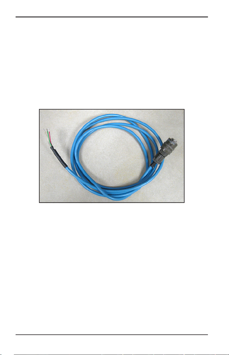
Note: Standard factory-assembled cables (see Figure 21 below) are
available from BHGE in lengths up to 600 m (2000 ft).
Figure 21: Two-Wire, Shielded, M Series Probe Cable
To connect the probe cable, refer to the accompanying photographs
and complete the following steps:
1. Insert the end of the probe cable with the bayonet-type connector
onto the probe and twist the shell clockwise until it snaps into a
locked position (approximately 1/8 turn).
IMPORTANT: Ensure that the power is OFF before proceeding.
22 dew.IQ User’s Manual
Page 31

Chapter 2. Installation
2.6.1 Connecting an M Series Probe (cont.)
IMPORTANT: To maintain good contact at the terminal block and to
avoid damaging the pins on the wiring connector, pull the
connector straight off (not at an angle) the terminal block,
and make the cable connections while the connector is off
the unit. After the wiring is complete, push the connector
straight onto the terminal block (not at an angle).
2. Remove the connector from the lower terminal block on the rear of
the dew.IQ (see Figure 22 below).
Figure 22: Bottom Connector Removed
3. Refer to Figure 23 below and Figure 24 on page 23 to connect the
end of the probe cable with the three leads to pins 16, 17 and 18
on the lower terminal block.
#17 Red
#16 Shield
#18 Green
Figure 23: M Series Probe Cable Connections
dew.IQ User’s Manual 23
Page 32

Chapter 2. Installation
2.6.1 Connecting an M Series Probe (cont.)
Figure 24: Making Probe Cable Connections to the Connector
4. Reinsert the connector into the lower terminal block on the rear of
the dew.IQ (see Figure 25 below).
Figure 25: Reinserting the Connector into the Terminal Block
24 dew.IQ User’s Manual
Page 33

Chapter 2. Installation
2.6.2 Connecting an IQ.probe
Complete the following steps to wire an IQ.probe to the dew.IQ:
1. Insert the end of probe cable (see Figure 26 below) with the
connector onto the probe and twist the connector head clockwise
until it is secure.
IMPORTANT: Ensure that the power is OFF before proceeding.
Figure 26: Four-Wire, IQ.probe Cable
dew.IQ User’s Manual 25
Page 34

Chapter 2. Installation
2.6.2 Connecting an IQ.probe (cont.)
IMPORTANT: To maintain good contact at the terminal block and to
avoid damaging the pins on the wiring connector, pull the
connector straight off (not at an angle) the terminal block,
and make the cable connections while the connector is off
the unit. After the wiring is complete, push the connector
straight onto the terminal block (not at an angle).
2. Remove the connector from the lower terminal block on the rear of
the dew.IQ (see Figure 27 below).
Figure 27: Bottom Connector Removed
3. Refer to Table 1 below and Figure 28 on page 26 to connect the
end of the probe cable with the four leads to pins 10, 11, 12 and 13
on the lower terminal block.
Table 1: IQ.probe Wiring Connections
Wire Color Pin Number Function
Brown 10 RTN
Black 11 COM –
White 12 COM +
Blue 13 +15V
Bare Wire* no connection Shield
*The cable shield lead requires no connection to the dew.IQ and
should be wrapped around the base of the other four leads.
26 dew.IQ User’s Manual
Page 35

Chapter 2. Installation
2.6.2 Connecting an IQ.probe (cont.)
Figure 28: Wiring the Cable to the Connector
4. Reinsert the connector into the lower terminal block on the rear of
the dew.IQ (see Figure 29 below).
Figure 29: Reinserting the Connector into the Terminal Block
Note: If there is a No Link error for the IQ.probe, check the wiring
connections and make sure there is no short between +15V and
RTN.
dew.IQ User’s Manual 27
Page 36

Chapter 2. Installation
2.6.3 Connecting the Analog Output
IMPORTANT: Ensure that the power is OFF before proceeding.
Refer to Table 2 below to connect your analog recorder to pins 14 and
15 on the lower terminal block on the back of the dew.IQ (see
Figure 22 on page 22 or Figure 27 on page 25).
IMPORTANT: To maintain good contact at the terminal block and to
avoid damaging the pins on the wiring connector, pull the
connector straight off (not at an angle) the terminal block,
and make the cable connections while the connector is off
the unit. After the wiring is complete, push the connector
straight onto the terminal block (not at an angle).
Table 2: Pin Assignments for Analog Output
Wire Color Pin Number Function
Black 14 Signal-
Red 15 Signal+
2.6.4 Connecting the Alarm Relays
Note: The cable for connecting the alarm relays is supplied by the
customer. Acceptable cables range from 16 to 26AWG.
The dew.IQ has one fault alarm relay and two high/low alarm relays.
Each alarm relay is a single-pole, double-throw contact set with the
following contacts (see Table 3 below for the connector pin
assignments):
• Normally Open (NO)
• Common (C)
• Normally Closed (NC)
Table 3: Pin Assignments for Alarm Relay Contacts
Contact Fault Alarm Alarm A Alarm B
Normally Open 1 4 7
Common 2 5 8
Normally Closed 3 6 9
28 dew.IQ User’s Manual
Page 37

Chapter 2. Installation
2.6.4.1 Connecting the High/Low Alarms (A and B)
IMPORTANT: Ensure that the power is OFF before proceeding.
Each of these alarms can be set to trip on either a high or low
condition. For a high alarm, the alarm will trip if the input exceeds the
setpoint. For a low alarm, the alarm will trip if the input drops below
the setpoint.
To wire the high/low alarm relays, complete the following steps:
1. Remove the connector from the upper terminal block on the rear of
the dew.IQ (see Figure 30 below).
IMPORTANT: To maintain good contact at the terminal block and to
avoid damaging the pins on the wiring connector, pull the
connector straight off (not at an angle) the terminal block,
and make the cable connections while the connector is off
the unit. After the wiring is complete, push the connector
straight onto the terminal block (not at an angle).
Figure 30: Removing the Upper Connector
2. Make the Alarm A and Alarm B connections to upper terminal
block connector, as indicated in Table 3 on page 27.
3. Reinsert the connector into the upper terminal block on the rear of
dew.IQ.
the
dew.IQ User’s Manual 29
Page 38

Chapter 2. Installation
2.6.4.2 Connecting the Fault Alarm
If enabled, the dew.IQ fault alarm trips when one or more of the
following faults occurs: power failure, range error (configurable) or
watchdog function system reset
Note: The watchdog function is a supervisory circuit that
automatically resets the unit whenever a system error occurs.
The fault alarm has two possible operating modes:
• Fail-Safe Mode: Using pins 2 and 3 provides a “normally closed”
contact. When the
fault alarm relay is energized to open the contact between pins
2 and 3. When a fault occurs, the fault alarm relay is
de-energized to close the contact between pins 2 and 3 and
trigger the alarm.
dew.IQ is operating in a non-fault state, the
• Non-Fail-Safe Mode: Using pins 1 and 2 provides a “normally
open” contact. When the
state, the fault alarm relay is de-energized with an open the
contact between pins 1 and 2. When a fault occurs, the fault
alarm relay is energized to close the contact between pins 1
and 2 and trigger the alarm.
dew.IQ is operating in a non-fault
IMPORTANT: Ensure that the power is off before proceeding.
To wire the fault alarm relay, complete the following steps:
1. Remove the connector from the upper terminal block on the rear of
the
dew.IQ (see Figure 30 on page 28).
IMPORTANT: To maintain good contact at the terminal block and to
avoid damaging the pins on the wiring connector, pull the
connector straight off (not at an angle) the terminal block,
and make the cable connections while the connector is off
the unit. After the wiring is complete, push the connector
straight onto the terminal block (not at an angle).
2. Make the fault alarm connections to upper terminal block
connector, as indicated in Table 3 on page 27.
3. Reinsert the connector into the upper terminal block on the rear of
the
dew.IQ.
30 dew.IQ User’s Manual
Page 39

Chapter 2. Installation
2.6.5 Connecting the Input Power
There are three input power configurations available for the dew.IQ:
• AC power cord (not used for wall mount units)
• DC power terminals (available for all configurations)
• AC power terminals (available for all configurations)
Proceed to the appropriate section to connect your input power.
2.6.5.1 Connecting the AC Power Cord
To install the AC power cord included with the dew.IQ, simply plug the
female connector end of the cable into the male connector on the rear
panel of the dew.IQ (see Figure 31 below and Figure 32 on page 31).
Note: This configuration is not used for AC powered wall mount units.
Figure 31: Inserting the AC Power Cable
dew.IQ User’s Manual 31
Page 40

Chapter 2. Installation
2.6.5.1 Connecting the AC Power Cord (cont.)
Figure 32: The AC Power Cable Installed
2.6.5.2 Connecting the DC Power Terminals
The DC power cable (with 14 to 26 AWG conductors) is supplied by the
customer. To connect the power cable to the dew.IQ input power
terminals (see Figure 19 on page 19) complete the following steps:
1. Remove the input power connector from the rear panel of the
dew.IQ (see Figure 33 below).
Figure 33: Removing the DC Power Connector
32 dew.IQ User’s Manual
Page 41

Chapter 2. Installation
2.6.5.2 Connecting the DC Power Terminals (cont.)
2. Strip the three power cable conductors by about 3/8” (10 mm).
3. Insert each wire into the appropriate connector pin (see Table 4
below) and tighten each screw to secure the wires in place.
Table 4: Pin Assignments for DC Power Connector
Wire Color Pin Function
Red + V+
Black - V-
Green GND Symbol Ground
IMPORTANT: Be sure that the dew.IQ chassis ground connection is
properly grounded.
4. Reinsert the power connector into the rear panel of the dew.IQ as
shown in Figure 34 below.
Figure 34: Reinserting the DC Power Connector
dew.IQ User’s Manual 33
Page 42

Chapter 2. Installation
2.6.5.3 Connecting the AC Power Terminals
IMPORTANT: Unlike the DC power connector, which has screw
terminals, the AC power connector has spring finger
terminals. It is essential that this connector be removed
from the dew.IQ for wiring to avoid putting stress on the
PCB, which may cause damage to the board.
The AC power cable (with 14 to 26 AWG conductors) is supplied by
the customer. To connect the power cable to the dew.IQ input power
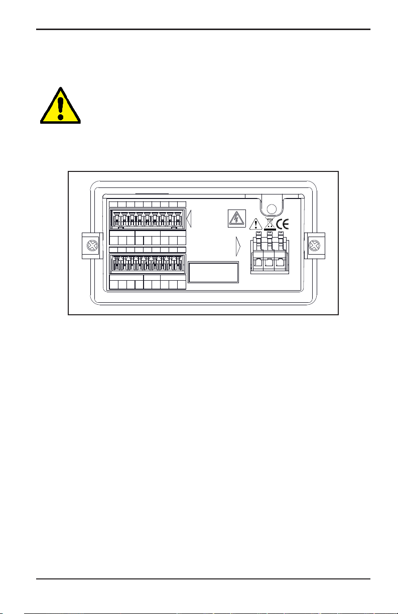
terminals, see Figure 20 on page 20 and complete the following steps:
1. Remove the input power connector from the rear panel of the
dew.IQ, as shown in Figure 35 below.
Figure 35: Removing the AC Power Connector
34 dew.IQ User’s Manual
Page 43

Chapter 2. Installation
2.6.5.3 Connecting the AC Power Terminals (cont.)
2. Strip the three power cable conductors by about 3/8” (10 mm).
3. Using a small screwdriver to assist in opening each spring finger
terminal, insert each wire into the appropriate connector pin (see
Table 5 below).
Table 5: Pin Assignments for AC Power Connector
Wire Color Pin Function
Black L1 Line
White L2/N Line 2 (230 VAC) or Neutral
Green G Ground
4. Reinsert the power connector into the rear panel of the
dew.IQ.
dew.IQ User’s Manual 35
Page 44

Chapter 2. Installation
36 dew.IQ User’s Manual
Page 45

Chapter 3. Initial Setup & Operation
Chapter 3. Initial Setup & Operation
3.1 Using the dew.IQ
All programming of the dew.IQ is done via the front panel keypad and
display, as illustrated below.
Right ArrowUp ArrowLeft ArrowDisplay
EnterDown ArrowCancel
The front panel components perform the following functions:
• Display - The programming menus and options are shown on
the LCD display screen.
• Enter - In most instances, press this key to save an entry
and/or to advance to the next screen.
• Cancel - In most instances, press this key to reject an entry
and/or to return to the previous screen.
• Lef t/Right Arrow Keys - Use these keys to move the cursor along
a row one character at a time in the direction indicated.
• Up/Down Arrow Keys - Use these keys to move the cursor
between rows one row at a time in the direction indicated.
Note: In those instances when the keys behave in a manner unique to a
specific screen, the differences will be described in that section.
dew.IQ User’s Manual 35
Page 46

Chapter 3. Initial Setup & Operation
3.1.1 Starting Up
After installation, the dew.IQ moisture analyzer can be configured to
meet the user’s requirements. While programming the instrument,
refer to one of the following menu maps:
• Figure 46 on page 104 when using an M Series probe (this probe
is used for the programming examples in this chapter.)
• Figure 47 on page 105 when using an IQ.probe
Upon the application of power, the dew.IQ performs some self checks
and then displays a measurement mode screen like the one below.
Status OK
–4.8°C
10:21
After startup, the
unlocked. To unlock the menu, press:
Cancel, Enter, Cancel.
Main Menu needs to be
3.1.2 Accessing the Menus
After unlocking the menu (as confirmed by the absence of the padlock
icon in the lower right corner), press Cancel to display the Main
Menu (see Figure 36 below). Use the arrow keys to select the desired
menu option and press Enter to access the highlighted option.
Pressing Cancel from the Main Menu returns the screen to the
Measurement Display.
Note: Menu items followed by an ellipsis (i.e., a series of three dots)
have submenus, while those without it take immediate action.
Main Menu
Display...
Output...
Alarm...
Logs...
Settings...
Service...
About...
LOCK
Figure 36: Main Menu
36 dew.IQ User’s Manual
Page 47

Chapter 3. Initial Setup & Operation
3.1.3 Entering Numeric Values
The dew.IQ has no numeric keypad. Numeric values are entered using
a “combination lock” entry (see Figure 37 below as an example):
1. Use the left and right arrow keys to select the digit to change.
The digit selected will be indicated with an .
2. Use the up and down arrow keys to increment or decrement
the selected digit.
Note: If incrementing or decrementing a digit would cause the numeric
value to leave its allowable range (maximum or minimum value),
the digit will not change.
3. After you have completed your numeric entry, press Enter
save the new value and return to the previous screen, or press
Cancel
to leave the original value intact and return to the
previous screen.
Set Output Span
Max:
+60.0
+060.0 DP °C
Min:
–110.0
/=Save =Cancel
Figure 37: Numeric Entry
to
dew.IQ User’s Manual 37
Page 48

Chapter 3. Initial Setup & Operation
3.2 Setting Up the Display
Main Menu
Display...
Output...
Alarm...
Logs...
Settings...
Service...
About...
LOCK
When the screen is unlocked, press the
Cancel
with several options. To set up the display,
select
Display... and press Enter . The
following screen appears:
3.2.1 Selecting the Primary Units
Display Menu
Unit Select
Decimal
Contrast
Select Display Unit:
DP
DP
PPMv
mg/m
g/m
kg/m
MH
°C
°F
3
3
3
PPMvNG
PPBv
MMSCFig
MMSCFng
Equiv DP
Equiv DP
To select the units for the primary display,
select
Unit Select and press Enter . The
following screen appears:
Use the arrow keys to select the desired
units and press Enter
returns to the Display Menu.
°
C
°
F
key and the Main Menu appears
. The screen
Note: If the IQ.probe is being used, FH replaces MH.
38 dew.IQ User’s Manual
Page 49

3.2.2 Setting the Decimal Places
Chapter 3. Initial Setup & Operation
Display Menu
Unit Select
Decimal
Contrast
To set the decimal places for unit values,
from the Display Menu use the arrow keys
to select
Decimal and press Enter . The
following screen appears:
Note: The decimal places setting determines the number of digits
displayed to the right of the decimal point (“.”) for the value, if
possible.
Set DP °C Format:
Max:
1
1 decimals
Min:
0
/=Save =Cancel
Use the arrow keys to change the number
of decimal places and press Enter
press Cancel
if no changes are desired.
The screen returns to the Display Menu.
3.2.3 Adjusting the Contrast
Display Menu
Unit Select
Decimal
Contrast
To adjust the display contrast, from the
Display Menu use the arrow keys to select
Contrast and press Enter . The following
screen appears:
, or
Adjust Display
2
1
4
3
/=Save =Cancel
dew.IQ User’s Manual 39
Use the
decrease the display contrast. Press Enter
to discard the changes. The screen returns
to the Display Menu.
Right/Left arrow keys to increase or
to save the changes, or press Cancel
Page 50

Chapter 3. Initial Setup & Operation
3.3 Setting Up the Analog Output
3.3.1 Entering the Output Menu
Main Menu
Display...
Output...
Alarm...
Logs...
Settings...
Service...
About...
LOCK
To set up the output, from the
choose
Output... and press Enter . The
following screen appears:
3.3.2 Selecting the Output Units
Output Menu
Units
Type
Upper
Lower
Select Output Unit:
DP °C
DP °F
PPMv
mg/m
3
Test
Trim...
g/m
kg/m
MH
3
3
From the
press Enter
appears:
Use the arrow keys to select the desired
units and press Enter
returns to the Output Menu.
Main Menu
Output Menu, select Units and
. The following screen
. The screen
Note: If the IQ.probe is being used, FH replaces MH.
40 dew.IQ User’s Manual
Page 51

Chapter 3. Initial Setup & Operation
3.3.3 Selecting an Output Type
IMPORTANT: Before changing the analog output type, refer to
“Selecting the Analog Recorder Output” on page 4 to
make sure that Switch S1 is set correctly (V for voltage
or I for current).
Output Menu
Units
Type
Upper
Lower
Output Menu
Select Output Type:
Test
Trim...
To change the output type, from the Output
Menu select Type and press Enter . A
screen similar to the following appears:
Use the arrow keys to select a new output
type. Press Enter
4-20mA
0-20mA
0-2V
(or Cancel
=Accept
=Cancel
and return to the Output Menu.
3.3.4 Changing the Output Span
Output Menu
Units
Type
Upper
Lower
Test
Trim...
To adjust the output span, from the
Menu select Upper and press Enter . A
screen similar to the following appears:
to save the selection
to keep the previous value),
Output
Set Output Span
Max:
+60.0
+060.0 DP °C
Min:
/=Save =Cancel
–110.0
Use the left and right arrow keys to select
each digit to be changed and the up and
down arrow keys to increase or decrease
its value. Press Enter
to save (or Cancel
to keep the previous value), and return
to the Output Menu.
dew.IQ User’s Manual 41
Page 52

Chapter 3. Initial Setup & Operation
3.3.5 Changing the Output Zero
Output Menu
Units
Type
Upper
Lower
Set Output Zero
Max:
–110.0 DP °C
Min:
/=Save =Cancel
Test
Trim...
+60.0
–110.0
To adjust the output zero, from the Output
Menu select Lower and press Enter . A
screen similar to the following appears:
Use the left and right arrow keys to select
each digit to be changed and the up and
down arrow keys to increase or decrease
its value. Press Enter
value (or Cancel
to save the new
to keep the previous
value), and return to the Output Menu.
42 dew.IQ User’s Manual
Page 53

Chapter 3. Initial Setup & Operation
3.3.6 Testing the Output
To verify proper operation of connected recording or SCADA
equipment, the dew.IQ can output test signals of known value. Based
on the percent of range selected, the Test Menu causes the dew.IQ to
output test signals that can be easily calculated. As examples, the
test signals for three commonly used range percentages are shown in
Table 6 below.
Table 6: Output Test Value Examples
Output Type 0% 50% 100%
0-20mA 0.00 mA 10.00 mA 20.00 mA
4-20mA 4.00 mA 12.00 mA 20.00 mA
0-2V 0.00 V 1.00 V 2.00 V
Output Menu
Units
Type
Upper
Lower
Output Test Value:
Max:
+050.00 %
Min:
/=Apply =Exit
Test
Trim...
+110.00
–25.00
To test the system output, from the Output
Menu select Test and press Enter . The
dew.IQ will check the output settings, and a
screen similar to the following appears:
Use the left and right arrow keys to select
each digit to be changed, and the up and
down arrow keys to increase or decrease
its value. Press Enter
value (or Cancel
to save the new
to keep the previous
value), and return to the Output Menu.
dew.IQ User’s Manual 43
Page 54

Chapter 3. Initial Setup & Operation
3.3.7 Trimming the Output
The Trim Menu enables the operator to compensate for differences in
the 0/4-20 mA or 0-2V dew.IQ test outputs and the readings on a
connected output device. To trim the analog output:
Output Menu
Units
Type
Upper
Upper
Output Trim
Reset Trim
Trim Zero
Trim Span
Output Trim
Reset Out Trim?
YES
=Accept
Output Trim
Reset Trim
Trim Zero
Trim Span
Test
Trim...
NO
=Cancel
Select Trim from the Output Menu and press
Enter
When performing a
dew.IQ requires you to first reset the trim.
. The following screen appears:
Trim operation, the
To reset the trim output, select Reset Trim
and press Enter
. The following screen
appears:
Use the left or right arrow keys to select
YES and press Enter . This cancels any
previous trim values, and returns the
dew.IQ to its factory adjustment. The
display returns to the previous screen.
To trim the zero value, select
press Enter
. A screen similar to the
Trim Zero and
following appears:
This step causes the dew.IQ to output 4.000 mA or 0.4 V on the output
being trimmed. The output value should then be read using the
connected analog device or a DVM.
44 dew.IQ User’s Manual
Page 55

Chapter 3. Initial Setup & Operation
3.3.7 Trimming the Output (cont.)
Enter the value read from the connected equipment as the Zero Trim
value, as follows:
Note: Since you cannot trim 0 mA or 0 V for negative offsets, trim for
the lower end of the scale is always at the 4 mA or 0.4 V output.
Enter Out Reading:
Max:
5.2000
04.0000 mA
Min:
3.0000
/=Save =Cancel
Use the left and right arrow keys to select
each digit to be changed, and the up and
down arrow keys to increase or decrease
its value. Press Enter
to save (or Cancel
to keep the previous value).
The
Output Trim
Reset Trim
Trim Zero
Trim Span
Output Trim menu returns with Trim
Span highlighted. To change the span
value, press Enter
. A screen similar to
the following appears:
This step causes the dew.IQ to output 20.000 mA or 2 V on the output
being trimmed. The output value should then be read using the
connected analog device or a DVM. Enter the value read from the
connected equipment as the
Enter Out Reading:
Max:
22.2000
20.0000 mA
Min:
10.0000
/=Save =Cancel
Span Trim value, as follows:
Use the left and right arrow keys to select
each digit to be changed, and the up and
down arrow keys to increase or decrease
its value. Press Enter
value (or Cancel
to save the new
to keep the previous
value).
Trimming is complete. To verify the accuracy, see “Testing the
Output” on page 43.
dew.IQ User’s Manual 45
Page 56

Chapter 3. Initial Setup & Operation
3.3.7 Trimming the Output (cont.)
Example:
1. Trim is reset, then Trim Zero is selected. The connected output
device reports 3.977 mA.
2. The operator enters “3.977” as the Zero Trim value.
3. Trim Span is selected. The connected output device reports 19.985
mA.
4. The operator enters “19.985” as the Span Trim value.
5. The dew.IQ adjusts the output accordingly to align the output with
the readings by the connected output device or a DVM.
6. Using the Test Menu, the operator verifies that a test value of 0%
now reads 4.000 mA at the connected output device, and a test
value of 100% now reads 20.000 mA.
3.4 Setting Up the Measurement Alarms
The dew.IQ has with two programmable high/low alarms and one fault
alarm relay. Use the instructions in this section to set up these alarms.
3.4.1 Selecting an Alarm Output
Alarm Menu [A]
Select
Status
Units
Type...
Alarm Menu [A]
Select Alarm:
A
B
=Accept
46 dew.IQ User’s Manual
Upper
Lower
Test
=Cancel
To set up the alarms, on the Main Menu
choose
Alarm and press Enter . Then,
from the Alarm Menu choose Select and
press Enter
. A screen similar to the
following appears:
Use the arrow keys to select the output (
B) to be set up and press Enter . The
or
display returns to the Alarm Menu.
A
Page 57

3.4.2 Selecting the Alarm Status
Chapter 3. Initial Setup & Operation
Alarm Menu [A]
Select
Status
Units
Type...
Alarm Menu [A]
Set Alarm Status:
ON
OFF
=Accept
Upper
Lower
Test
=Cancel
To select the alarm status, from the Alarm
Menu select Status and press Enter . The
following screen appears:
Use the arrow keys to select
press Enter
Alarm Menu.
3.4.3 Selecting the Alarm Units
Alarm Menu [A]
Select
Status
Units
Type...
Upper
Lower
Test
To select the alarm units, from the
Menu select Units and press Enter . The
following screen appears:
OFF or ON and
. The display returns to the
Alarm
Select Alarm Unit:
DP °C
DP °F
PPMv
mg/m
3
g/m
kg/m
MH
3
3
Use the arrow keys to select the desired
alarm units. Press Enter
selection (or Cancel
to save the
to keep the
previous value), and return to the Alarm
Menu.
Note: If the IQ.probe is being used, FH replaces MH.
dew.IQ User’s Manual 47
Page 58

Chapter 3. Initial Setup & Operation
3.4.4 Selecting an Alarm Type
Alarm Menu [A]
Select
Status
Units
Type...
Select Alarm Type:
Setpoint
In Band
Out Band
Upper
Lower
Test
To change the alarm type, from the Alarm
Menu select Type and press Enter . A
screen similar to the following appears:
Use the arrow keys to select an alarm type
(see “How the Alarm Types Work” on
page 49). Press Enter
to keep the previous value), and return
to save (or Cancel
to the Alarm Menu.
48 dew.IQ User’s Manual
Page 59

Chapter 3. Initial Setup & Operation
3.4.5 How the Alarm Types Work
The available alarm types (see Figure 38 below) for the dew.IQ are:
• Setpoint: The alarm activates when the selected parameter exceeds the
upper limit. It deactivates when the selected parameter is less than the
lower limit.
• Inner Band: The alarm activates when the selected parameter is between
the upper limit and the lower limit. It deactivates when the selected
parameter exceeds the upper limit or is less than the lower limit.
• Outer Band: The alarm activates when the selected parameter exceeds
the upper limit or is below the lower limit. It deactivates when the
selected parameter is between the upper limit and the lower limit.
Trip
Upper
Setpoint
Reset
Hysteresis
Lower
In Band
Out Band
Trip
Reset
Reset
Reset
Trip
Reset
Trip
Trip
Figure 38: Available Alarm Types
dew.IQ User’s Manual 49
Page 60

Chapter 3. Initial Setup & Operation
3.4.6 Setting the Alarm Span
Alarm Menu [A]
Select
Status
Units
Type...
Upper
Lower
Test
To adjust the alarm span, from the Alarm
Menu select Upper and press Enter . A
screen similar to the following appears:
Use the left and right arrow keys to select
Max:
+60.0
+000.0 DP °C
Min:
–110.0
/=Save =Cancel
each digit to be changed and the up and
down arrow keys to increase or decrease
its value. Press Enter
value (or Cancel
value), and return to the Alarm Menu.
3.4.7 Setting the Alarm Zero
Alarm Menu [A]
Select
Status
Units
Type...
Upper
Lower
Test
To adjust the alarm zero, from the
Menu select Lower and press Enter . A
screen similar to the following appears:
to save the new
to keep the previous
Alarm
Use the left and right arrow keys to select
Max:
+60.0
+000.0 DP °C
Min:
–110.0
/=Save =Cancel
each digit to be changed and the up and
down arrow keys to increase or decrease
its value. Press Enter
value (or Cancel
to save the new
to keep the previous
value), and return to the Alarm Menu.
50 dew.IQ User’s Manual
Page 61

3.4.8 Testing the Alarm Relays
Chapter 3. Initial Setup & Operation
Alarm Menu [A]
Select
Status
Units
Type...
Alarm Menu [A]
Alarm is TRIPPED
Reset
=Accept
Upper
Lower
Test
Trip
=Cancel
To test the alarm relay and devices
connected to it, from the Alarm Menu select
Test and press Enter . A screen similar
to the following appears:
Use the left and right arrow keys to select
Reset or Trip and press Enter . If Reset
was selected, the message Alarm is RESET
appears. If Trip was selected, the message
Alarm is Tripped appears. Press Cancel
to return to the Alarm Menu.
dew.IQ User’s Manual 51
Page 62

Chapter 3. Initial Setup & Operation
3.5 Viewing System Information
Main Menu
Display...
Output...
Alarm...
Logs...
Settings...
Service...
About...
LOCK
To view the dew.IQ system information,
from the Main Menu choose About... and
press Enter
. Proceed to the following
sections.
Note: The information in the following screens are examples only. Your
dew.IQ will display the information for your specific unit.
3.5.1 Checking the ID
About dew.IQ
ID
Status
Version
Probe
Menu: X
GE Sensing dew.IQ
GE Sensing MTS-6
GE Sensing MTS-6
Copyright © 2012
Copyright © 2009
General Electric Co.
General Electric Co.
Unit SN: 111111
Unit SN: XXXXXX
Probe SN: 90104
Probe SN: XXXXXX
Wiring
To check the identity information of the
dew.IQ, from the About dew.IQ menu select
ID and press Enter . A screen similar to
the following appears:
The information includes serial numbers
for the
dew.IQ unit and the attached probe.
To return to the About dew.IQ menu, press
Cancel
.
52 dew.IQ User’s Manual
Page 63

3.5.2 Checking the Status
Chapter 3. Initial Setup & Operation
About dew.IQ
ID
Status
Version
Probe
Menu: X
Uptime: 0d 00h
GE Sensing MTS-6
GE Sensing MTS-6
SD Card Installed.
Copyright © 2009
Format is FAT16
General Electric Co.
0.27 MB used
Unit SN: XXXXXX
244.68 MB free
Probe SN: XXXXXX
Wiring
To check the status of the MicroSD card,
from the
and press Enter
About dew.IQ menu select Status
. A screen similar to the
following appears:
The information includes the format,
amount of used space and amount of free
space for an installed SD card. To return to
About dew.IQ menu, press Cancel .
the
3.5.3 Checking the Software Version
Note: The information in the following screens is a typical example
only. Your unit always displays your actual information.
About dew.IQ
ID
Status
Version
Probe
Wiring
To check the software version of the
dew.IQ, from the About dew.IQ menu select
Version and press Enter . A screen
similar to the following appears:
Menu: X
Prog: STD.001.A
GE Sensing MTS-6
GE Sensing MTS-6
Copyright © 2009
Probe SN: XXXXXX
dew.IQ User’s Manual 53
The information includes the program
number (i.e., the firmware version). To
return to the
Cancel
About dew.IQ menu, press
.
Page 64

Chapter 3. Initial Setup & Operation
3.5.4 Checking the Probe
Note: The information in the following screens is a typical example
only. Your unit always displays your actual information.
About dew.IQ
ID
Status
Version
Probe
Menu: X
Probe: Standard
GE Sensing MTS-6
GE Sensing MTS-6
Copyright © 2009
Probe SN: XXXXXX
Menu: X
Probe:
GE Sensing MTS-6
GE Sensing MTS-6
IQ.probe v. 1.A
Copyright © 2009
S/N: 90104
Probe SN: XXXXXX
Wiring
To check the probe details, from the About
dew.IQ menu select Probe and press
Enter
. A screen similar to one of the
following appears:
For an
M Series probe, this probe
information is shown. To return to the
About dew.IQ menu, press Cancel .
For an IQ.probe, this probe information is
shown. To return to the About dew.IQ
menu, press Cancel
.
54 dew.IQ User’s Manual
Page 65

3.5.5 Checking the Wiring
Chapter 3. Initial Setup & Operation
About dew.IQ
ID
Status
Version
Probe
Menu: x
FAULT
ALM A ALM B
C
–+
Wiring
CC
2
To view the
the About dew.IQ menu select Wiring and
press Enter
following appears:
When you are ready to return to the
Main menu, press Cancel twice.
91
3.6 Locking the Main Menu
Main Menu
Display...
Output...
Alarm...
Logs...
Settings...
Service...
About...
LOCK
To lock out access to changing menu
settings, from the
and press Enter
normal measurement mode.
dew.IQ wiring diagram, from
. A screen similar to the
dew.IQ
Main Menu choose LOCK
. The display returns to
Note: To unlock the menu, refer to “Starting Up” on page 36.
dew.IQ User’s Manual 55
Page 66

Chapter 3. Initial Setup & Operation
[no content intended for this page]
56 dew.IQ User’s Manual
Page 67

Chapter 4. Data Logging
4.1 Checking the Data Log Status
Chapter 4. Data Logging
Logging Menu
Status
Manage...
Settings...
Eject Card
To check the data log status, from the
Logging Menu select Status and press Enter
. A screen similar to the following
appears:
The current data log status is displayed.
Data Log RUNNING
File: 01270803
Interval: 60 secs
Size: 23 KB
After about 10 seconds or upon pressing
Cancel
(whichever occurs first), the
screen returns to the Logging Menu.
4.2 The Log Settings Menu
Note: To access the Settings... option in the Logging Menu, the log file
must be stopped (see “Pausing or Closing a Log” on page 62).
4.3 Setting the Log Units
Logging Menu
Status
Manage...
Settings...
Eject Card
From the
and press Enter
appears:
Logging Menu select Settings...
. The following screen
Set Log Params
Units
Interval
FieldSep
Flags
dew.IQ User’s Manual 57
To set units to log, from the
menu, select
Units and press Enter . The
following screen appears.:
Set Log Params
Page 68

Chapter 4. Data Logging
4.3 Setting the Log Units (cont.)
Units to Log:
1
2
3
4
Units to Log:
Choose Unit Action:
Modify
=Accept
Select Unit #1:
DP °C
DP °F
PPMv
mg/m
3
DP °F
-----
-----
DP °C111
Remove
=Cancel
g/m
kg/m
MH
3
3
Use the arrow keys to select the unit to log,
and press Enter
. The following screen
appears:
To change the unit setting, select
and press Enter
. The following screen
appears:
Use the arrow keys to select the first unit
to be logged and press Enter
screen returns to the Units to Log menu.
Note: If the IQ.probe is being used, FH replaces MH.
Modify
. The
Units to Log:
Choose Unit Action:
Modify
=Accept
Remove
=Cancel
To remove a unit, from the
menu, select
Remove and press Enter .
Select the unit to be removed, press Enter
, to delete the selected unit. Press
Cancel
to return to the Set Log Params
Units to Log
menu.
58 dew.IQ User’s Manual
Page 69

4.4 Setting the Log Interval
Chapter 4. Data Logging
Set Log Params
Units
Interval
FieldSep
Flags
Set Log Interval
Max:
86400
00005 seconds
Min:
1
/=Save =Cancel
To set the log interval, from the Set Log
Params menu, select Interval and press
Enter
. The following screen appears:
Use the left and right arrow keys to select
each digit to be changed and the up and
down arrow keys to increase or decrease
its value. Press Enter
value (or Cancel
value), and return to the Set Log Params
menu.
4.5 Setting a Log Field Separator
Set Log Params
Units
Interval
FieldSep
Flags
To designate a text character to separate
the log fields, from the
menu select
The following screen appears:
to save the new
to keep the previous
Set Log Params
FieldSep and press Enter .
Set Log Params
Field Separator:
Comma
dew.IQ User’s Manual 59
Tab
=Accept
=Cancel
Use the arrow keys to select the text
character used to separate the log fields
and press Enter
. The screen returns to
the Set Log Params menu.
Page 70

Chapter 4. Data Logging
4.6 Setting the Log Status Flags
The flags used to identify the log status are as follows:
• Range Err • No Refs
• Over Range • No Data
• Under Range • No Cal
• No Comm • Write Err
• No Link • Read Err
• Bad CRC • ADC Failure
• Bad Message • Cal Error
• Auto Cal •
Set Log Params
Units
Interval
FieldSep
Flags
Set Log Params
Log Status Flags:
On
Off
=Accept
=Cancel
To turn log status flags on or off, from the
Set Log Params menu select Flags and
press Enter
. The following screen
appears:
Use the arrow keys to select
press Enter
Set Log Params menu. Then, press Cancel
to return to the Logging Menu.
. The screen returns to the
OFF or ON and
60 dew.IQ User’s Manual
Page 71

4.7 Managing Log Files
Chapter 4. Data Logging
Logging Menu
Status
Manage...
Settings...
Eject Card
To manage the log file status, from the
Logging Menu select Manage and press
Enter
. If no log has been created, the
following screen appears:
4.7.1 Creating a New Log
Note: The New Log option is available only if there are no logs currently
running or paused. All running or paused logs must be closed
before proceeding. Note that a closed log cannot be resumed.
Manage Log Files
New Log
Directory
Erase Log
Log Created.
New Log:
File: 01281244
was created.
To create a new log, from the
Files menu select New Log and press
Enter
. A screen similar to the following
appears:
A file name, which corresponds to the date
and time the log is started, is assigned to
the new log by the
dew.IQ. For example, a
log started on May 1 at 4:37 pm will be
named 05011637. After about 10 seconds
Manage Log
or upon pressing Cancel
occurs first), the screen returns to the
Manage Log Files menu.
(whichever
Note: When a new log is created, the New Log option in the Manage Log
Files menu changes to a Pause/Close option.
dew.IQ User’s Manual 61
Page 72

Chapter 4. Data Logging
4.7.2 Pausing or Closing a Log
Manage Log Files
Pause/Close
Directory
Erase Log
After a new log is created, it can be paused
or closed at any time. To pause or close a
log, from the
Pause/Close and press Enter . The
Manage Log Files menu select
following screen appears:
Manage Log Files
File: 06150618
PAUSE
=Accept
CLOSE
=Cancel
The log file name is shown in the header.
Select
Pause or Close and press Enter .
The screen returns to the Manage Log Files
menu.
Note: After a log is paused, the Pause/Close option in the Manage Log
Files menu changes to a Resume/Close option.
62 dew.IQ User’s Manual
Page 73

4.7.3 Resuming a Log
Chapter 4. Data Logging
Manage Log Files
Resume/Close
Directory
Erase Log
A paused log can be resumed or closed at
any time. To resume or close a log, from
the Manage Log Files menu select
Resume/Close and press Enter . The
following screen appears:
Manage Log Files
File: 06150618
RESUME
=Accept
CLOSE
=Cancel
Select
Files menu.
Resume or Close and press Enter
. The screen returns to the Manage Log
Note: After a log is resumed, the Manage Log Files menu displays the
Pause/Close option again.
Note: If a log is running and the dew.IQ reboots due to a power failure,
the log returns to its status prior to the power failure.
4.7.4 Viewing the Log Directory
Manage Log Files
New Log
Directory
Erase Log
To view the existing log file names, select
Directory and press Enter . A screen
similar to the following appears:
File Listing
01270801
1
2
01270802
01270803
3
01281238
4
1/27/2010 08:01 162 bytes
dew.IQ User’s Manual 63
01281240
5
6
01281241
7
01281242
8
01281243
When a log file is highlighted, the date,
time and size of that log file is shown at the
bottom of the screen. Use the arrow keys to
move from one log file to another. To
return to the
Cancel
Manage Log Files menu, press
.
Page 74

Chapter 4. Data Logging
4.7.5 Deleting Log Files
Manage Log Files
Pause/Close
Directory
Erase Log
File to Erase:
01270801
1
2
01270802
01270803
3
01281238
4
1/27/2010 08:01 162 bytes
File to Erase:
ERASE Log 01281243?
NO
YES
=Accept
01281240
5
6
01281241
7
01281242
8
01281243
=Cancel
To erase existing log files, from the Manage
Log Files menu, select Erase Log and press
Enter
. The File Listing screen appears:
Using the arrow keys, move to the name of
the log file to be deleted and press Enter
. The following screen appears:
Using the arrow keys, select YES to erase
the log file, or NO to keep the log file. Press
Enter
Listing. If YES was selected, the erased log
and the screen returns to File
file is no longer listed. If NO was selected,
the log file is still listed. Press Cancel
to
return to the Manage Log Files menu.
64 dew.IQ User’s Manual
Page 75

Chapter 4. Data Logging
4.8 Ejecting the MicroSD Card
Ejecting the MicroSD card requires two steps:
1. Closing all active logs. Complete this step by following the
instructions in “Pausing or Closing a Log” on page 62.
2. Ejecting the MicroSD card. Accomplish this as follows:
IMPORTANT: Physically removing the MicroSD card from the dew.IQ
without first closing all active logs and ejecting the card
will not damage either the card or the dew.IQ, but it may
result in data loss.
Logging Menu
Status
Manage...
Settings...
Eject Card
Logging Menu
Eject SD Card?
EJECT
=Accept
If
EJECT was selected above, the MicroSD card may now be physically
CANCEL
=Cancel
To eject the SD card, from the
Menu, select Eject Card and press Enter .
The following screen appears:
Use the arrow keys to select
CANCEL and press Enter . The screen
returns to the Logging Menu. Press
Cancel
to return to the Main Menu.
Logging
EJECT or
removed from the dew.IQ. To remove and read the card see
Appendix C, “Reading the MicroSD Card” on page 107.
dew.IQ User’s Manual 65
Page 76

Chapter 4. Data Logging
4.9 Viewing Data Log Files
Any standard MicroSD card reader may be used to read the dew.IQ
MicroSD card on a PC. The log files are stored in text format, and any
word processing or spreadsheet program may be used to read the data.
See “Reading the MicroSD Card” on page 107, for instructions and
examples on how to work with the dew.IQ log files.
66 dew.IQ User’s Manual
Page 77

Chapter 5. Programming the Settings Menu
Chapter 5. Programming the Settings Menu
5.1 Entering Your Passcode
To access the Settings Menu, proceed as follows:
Main Menu
Display...
Output...
Alarm...
Logs...
Settings Menu is the only user menu that requires a passcode. The
The
Settings...
Service...
About...
LOCK
To access the
Menu select Settings... and press Enter .
Settings menu, from the Main
passcode is a four-digit number that enables only authorized users to
enter setup data. The dew.IQ prompts you to enter your passcode
whenever you attempt to program most of the Settings Menu options,
as shown below.
IMPORTANT: See page 125 near the end of this manual for your factory
default passcode.
User Passcode:
0000
Use the left and right arrow keys to select
each digit to be changed and the up and
down arrow keys to increase or decrease
its value. After the passcode has been
/=Save =Cancel
entered, press Enter
to proceed.
Note: The AutoCal, Clock and DpC Offset submenus do not require a
passcode for access.
Note: After entering your passcode, all menus that require the
passcode for access will display a U in the lower right corner to
indicate that the Settings menu has been Unlocked.
dew.IQ User’s Manual 67
Page 78

Chapter 5. Programming the Settings Menu
5.2 Setting the Fault Alarm
Note: Access to this menu requires a passcode (see “Entering Your
Passcode” on page 67).
Settings Menu
Fault Alm...
AutoCal...
Cal Data...
V/V Ratio...
Clock...
Probes
DpC Offset
To configure the fault alarm, from the
Settings Menu select Fault Alarm and press
Enter
. Then, enter your passcode and
press Enter
5.2.1 Setting the Fault Alarm Status
Fault Alarm
Status
Type
Options
Test
Fault Alarm
Set Fault Alarm:
ON
OFF
=Accept
=Cancel
To check the status of the fault alarm, from
the Fault Alarm menu, select Status and
press Enter
appears:
To change the status of the fault alarm,
OFF or ON and press Enter . The
select
screen returns to the Fault Alarm menu.
.
. The following screen
68 dew.IQ User’s Manual
Page 79

Chapter 5. Programming the Settings Menu
5.2.2 Setting the Fault Alarm Type
Note: For more information on alarm types, see “How the Alarm
Types Work” on page 49.
Fault Alarm
Status
Type
Options
Test
Fault Alarm
Fault Relay:
Fail-Safe
=Accept
=Cancel
Normal
To check or change the fault alarm type,
select
Type and press Enter . The
following screen appears:
To change the type of fault alarm used,
select the non-highlighted option and
press
Enter
Alarm menu.
. The screen returns to the Fault
5.2.3 Setting the Fault Alarm Options
Fault Alarm
Status
Type
Options
Test
To check or change the
select
Options and press Enter . The
following screen appears:
Fault Alarm options,
Fault Alarm
No
Yes
=Accept
=Cancel
To set the
select
screen returns to the Fault Alarm menu.
Then, press Cancel
Alarm on Range Error response,
Yes or No and press Enter . The
to return to the
Settings Menu.
dew.IQ User’s Manual 69
Page 80

Chapter 5. Programming the Settings Menu
5.2.4 Testing the Fault Alarm
Fault Alarm
Status
Type
Options
Test
Fault Alarm
Reset
Trip
=Accept
=Cancel
To test the
press Enter
appears:
To reset the fault alarm, select
press Enter
select
Cancel
Fault Alarm, select Test and
. The following screen
Reset and
. To trip the fault alarm,
Trip and press Enter . Press
twice to return to the Settings
Menu.
5.3 Setting AutoCal
Note: Access to this menu does not require a passcode.
Note: The AutoCal Settings menu is only available for an M Series
probe. This menu is not available for an IQ.probe.
Settings Menu
Fault Alm...
AutoCal...
Cal Data...
V/V Ratio...
AutoCal Settings
Interval
Cal Now
70 dew.IQ User’s Manual
Clock...
Probes
DpC Offset
To change the AutoCal settings, from the
Settings Menu select AutoCal and press
Enter
. The following screen appears:
To change the AutoCal interval settings,
Interval and press Enter . A screen
select
similar to the following appears:
Page 81

5.3 Setting AutoCal (cont.)
Use the left and right arrow keys to select
Max:
72
08 Hours
Min:
0
/=Save =Cancel
each digit to be changed and the up and
down arrow keys to increase or decrease
its value. Press Enter
value (or Cancel
value), and return to the AutoCal Settings
menu.
Chapter 5. Programming the Settings Menu
to save the new
to keep the previous
AutoCal Settings
Interval
Cal Now
AutoCal Settings
AutoCal Now
No
Yes
=Accept
=Cancel
To manually initiate an immediate
one-time
Enter
AutoCal, select Cal Now and press
. A screen similar to the following
appears:
To initiate the
AutoCal, select Yes. To
cancel the AutoCal select No. Press Enter
to confirm your selection and return to
the AutoCal Settings menu.
dew.IQ User’s Manual 71
Page 82

Chapter 5. Programming the Settings Menu
5.4 Entering Calibration Data for an M Series Probe
Note: Access to this menu requires a passcode (see “Entering Your
Passcode” on page 67).
Note: If you are using an IQ.probe, see “Viewing Calibration Data for
an IQ.probe” on page 75.
Settings Menu
Fault Alm...
AutoCal...
Cal Data...
V/V Ratio...
Clock...
Probes
DpC Offset
To enter M Series probe calibration data,
from the Settings Menu select Cal Data and
press Enter
and press Enter
appears:
Cal Data
MH/DP Cal...
FH DPCal...
Cal Reference...
Probe SN
For a standard M Series probe, the MH/DP
Cal option is highlighted by default. Press
Enter
and continue to the next section.
5.4.1 Selecting the Number of Points
Edit MH/DP Cal
Select Num of Points
Select Cal Point
Edit MH
Edit DP/°C
To select the number of points, highlight
Select Num of Points and press Enter .
The following screen appears:
. Then, enter your passcode
. The following screen
Use the left and right arrow keys to select
Max:
20
14
Min:
2
/=Save =Cancel
each digit to be changed and the up and
down arrow keys to increase or decrease
its value. Press Enter
value (or Cancel
to save the new
to keep the previous
value), and return to Edit MH/DP Cal.
72 dew.IQ User’s Manual
Page 83

Chapter 5. Programming the Settings Menu
5.4.2 Selecting the Calibration Point
Edit MH/DP Cal
Select Num of Points
Select Cal Point
Edit MH
Edit DP/°C
To select the calibration point, highlight
Select Cal Point and press Enter . The
following screen appears:
Use the left and right arrow keys to select
Max:
13
00
Min:
0
/=Save =Cancel
each digit to be changed and the up and
down arrow keys to increase or decrease
its value. Press Enter
value (or Cancel
value), and return to the Edit MH/DP Cal
menu.
5.4.3 Entering the MH Calibration
Edit MH/DP Cal
Select Num of Points
Select Cal Point
Edit MH
Edit DP/°C
To enter the MH calibration value for the
selected point, highlight
Enter
. The following screen appears:
to save the new
to keep the previous
Edit MH and press
Set MH [00]
Max:
4.0000
0.0000
Min:
0.0000
/=Save =Cancel
Use the left and right arrow keys to select
each digit to be changed and the up and
down arrow keys to increase or decrease
its value. Press Enter
value (or Cancel
to save the new
to keep the previous
value), and return to the Edit MH/DP Cal
menu.
dew.IQ User’s Manual 73
Page 84

Chapter 5. Programming the Settings Menu
5.4.4 Entering the Dew Point Calibration
Edit MH/DP Cal
Select Num of Points
Select Cal Point
Edit MH
Edit DP/°C
Set DP/°C [00]
Max:
+100.00
–110.00 °C
Min:
–200.00
/=Save =Cancel
To enter the dew point calibration value
for the selected point, highlight Edit DP/°C
and press Enter
. The following screen
appears:
Use the left and right arrow keys to select
each digit to be changed and the up and
down arrow keys to increase or decrease
its value. Press Enter
value (or Cancel
to save the new
to keep the previous
value), and return to the Edit MH/DP Cal
menu. Press Cancel
Data menu.
to return to the Cal
74 dew.IQ User’s Manual
Page 85

Chapter 5. Programming the Settings Menu
5.5 Viewing Calibration Data for an IQ.probe
Note: Access to this menu requires a passcode (see “Entering Your
Passcode” on page 67).
Note: If you are using an M Series probe, see “Entering Calibration
Data for an M Series Probe” on page 72.
Settings Menu
Fault Alm...
AutoCal...
Cal Data...
V/V Ratio...
Clock...
Probes
DpC Offset
To view the IQ.probe calibration data, from
the Settings Menu select Cal Data and press
Enter
. Then, enter your passcode and
press Enter
appears:
Cal Data
MH/DP Cal...
FH/DPCal...
Cal Reference...
Probe SN
For an
highlighted by default. Press Enter
continue to the next section.
IQ.probe, the FH/DP Cal option is
5.5.1 Selecting the Calibration Point
To select the calibration point, highlight
Select Cal Point
Read FH Value
Read DP Value
Select Cal Point and press Enter . The
following screen appears:
. The following screen
and
Use the left and right arrow keys to select
each digit and the up and down arrow keys
Max:
13
00
Min:
0
/=Save =Cancel
to increase or decrease its value. Press
Enter
to save the new value (or Cancel
to keep the previous value), and return
to Read FH/DP Calibration.
dew.IQ User’s Manual 75
Page 86

Chapter 5. Programming the Settings Menu
5.5.2 Reading the FH Value
To view the FH calibration value for the
Select Cal Point
Read FH Value
Read DP Value
selected point, highlight Read FH and press
Enter
. The following screen appears:
Viewing FH [00]
Read Only
10.6821
=Exit
The FH value is for viewing only. When you
are ready, press Cancel
Read FH/DP Calibration menu.
5.5.3 Reading the DP Value
To view the DP calibration value for the
Select Cal Point
Read FH Value
Read DP Value
Viewing DP [00]
Read Only
–110.00
=Exit
selected point, highlight
press Enter
appears:
The DP value is for viewing only. When you
are ready, press Cancel
Read FH/DP Calibration menu. Press
Cancel
Menu.
to return to the
Read DP and
. The following screen
to return to the
twice to return to the Settings
76 dew.IQ User’s Manual
Page 87

Chapter 5. Programming the Settings Menu
5.6 Reading and Setting the Calibration References
Note: This section applies only to an M Series probe. The Cal Reference
menu is not available for an IQ.probe.
Note: Access to this menu requires a passcode (see “Entering Your
Passcode” on page 67).
IMPORTANT: The dew.IQ is factory programmed with high and low
reference MH values. These values are generated from a
factory lab calibration and should not be changed without
first consulting BHGE technical support. Changes to these
values will alter the accuracy of your measurements.
Settings Menu
Fault Alm...
AutoCal...
Cal Data...
V/V Ratio...
Cal Data
MH/DP Cal...
FH/DPCal...
Cal Reference...
Probe SN
Clock...
Probes
DpC Offset
To update the calibration references, from
the Settings Menu select Cal Data and press
Enter
press Enter
. Then, enter your passcode and
. The following screen
appears:
To view or edit the calibration reference
settings, select
Enter
. Proceed to the next section.
Cal Reference and press
dew.IQ User’s Manual 77
Page 88

Chapter 5. Programming the Settings Menu
5.6.1 Setting the Calibration High Reference
Edit Cal Refs
High Reference
Low Reference
To update the high reference setting, from
the Edit Cal Refs menu select High
Reference and press Enter . A screen
similar to the following appears:
High MH Ref.
Max:
15.0000
3.0419 MH
Min:
0.0000
/=Save =Cancel
Use the left and right arrow keys to select
each digit to be changed and the up and
down arrow keys to increase or decrease
its value. After the changes have been
made, press Enter
. The screen returns
to the Edit Cal Refs menu.
5.6.2 Setting the Calibration Low Reference
Edit Cal Refs
High Reference
Low Reference
To update the low reference setting, from
Edit Cal Refs menu select Low
the
Reference and press Enter . A screen
similar to the following appears:
Low MH Ref.
Max:
15.0000
0.1752 MH
Min:
0.0000
/=Save =Cancel
Use the left and right arrow keys to select
each digit to be changed and the up and
down arrow keys to increase or decrease
its value. After the changes have been
made, press Enter
. The screen returns
to the Edit Cal Refs menu.
78 dew.IQ User’s Manual
Page 89

Chapter 5. Programming the Settings Menu
5.7 Entering an M Series Probe Serial Number
Note: This section applies only to an M Series probe. The Probe SN
menu is not available for an IQ.probe.
Note: Access to this menu requires a passcode (see “Entering Your
Passcode” on page 67).
Settings Menu
Fault Alm...
AutoCal...
Cal Data...
V/V Ratio...
Cal Data
MH/DP Cal...
FH/DPCal...
Cal Reference
Probe SN
Enter M2 Probe SN
Max:
99999999
10000000
Min:
/=Save =Cancel
Clock...
Probes
DpC Offset
0
To update the probe serial number, from
the Settings Menu select Cal Data and press
Enter
press Enter
. Then, enter your passcode and
. The following screen
appears:
To view or edit the probe serial number,
select
Probe SN and press Enter . The
following screen appears:
Use the left and right arrow keys to select
each digit to be changed and the up and
down arrow keys to increase or decrease
its value. After the changes have been
made, press Enter
. The screen returns
to the Cal Data menu.
dew.IQ User’s Manual 79
Page 90

Chapter 5. Programming the Settings Menu
5.8 Setting the Volume Mixing Ratio
Note: Access to this menu requires a passcode (see “Entering Your
Passcode” on page 67).
Settings Menu
Fault Alm...
AutoCal...
Cal Data...
V/V Ratio...
Clock...
Probes
DpC Offset
To set the volume mixing ratio, from the
Settings Menu select V/V Ratio and press
Enter
press Enter
sections.
5.8.1 Setting the Pressure Units
Volume Mixing Ratio
Press. Units
Press. Value
k x PPMv
Volume Mixing Ratio
Pressure Units:
kPa(a)
=Accept
Bar(g)
PSI(g)
=Cancel
To set the pressure units, select
Units and press Enter . The following
screen appears:
Use the left and right arrow keys to
highlight the desired units. Press Enter
to save the new units (or Cancel to
keep the previous units) and return to the
Volume Mixing Ratio menu.
. Then, enter your passcode and
. Proceed to the following
Press.
80 dew.IQ User’s Manual
Page 91

Chapter 5. Programming the Settings Menu
5.8.2 Setting the Pressure Value
Volume Mixing Ratio
Press. Units
Press. Value
k x PPMv
Line Pressure:
Max:
70000.000
00101.325 kPa(a)
Min:
0.000
/=Save =Cancel
To set the pressure value, select Press.
Value and press Enter . The following
screen appears:
Use the left and right arrow keys to select
each digit to be changed and the up and
down arrow keys to increase or decrease
its value. Press Enter
value (or Cancel
value) and return to the Volume Mixing
Ratio menu.
5.8.3 Setting the k x PPMv Multiplier
Volume Mixing Ratio
Press. Units
Press. Value
k x PPMv
To set the multiplier value, select
and press Enter
appears:
to save the new
to keep the previous
k x PPMv
. The following screen
k x PPMv Multiplier
Max:
100.000
001.000
Min:
0.001
/=Save =Cancel
Use the left and right arrow keys to select
each digit to be changed and the up and
down arrow keys to increase or decrease
its value. Press Enter
value (or Cancel
to save the new
to keep the previous
value) and return to the Volume Mixing
Ratio menu.
dew.IQ User’s Manual 81
Page 92

Chapter 5. Programming the Settings Menu
5.9 Setting the System Clock
Note: Access to this menu does not require a passcode.
Settings Menu
Fault Alm...
AutoCal...
Cal Data...
V/V Ratio...
Clock...
Probes
DpC Offset
5.9.1 Setting the Hour
Thu 2/4/2010 13:44
Hour
Minutes
Month
Date
Set Hour [0-23]:
Max:
13
Min:
/=Save =Cancel
Year
23
0
To set the system clock, from the Settings
Menu select Clock and press Enter to
display the current day, date and time. To
make changes, see the following sections.
To change the hour, select
Enter
. The following screen appears:
Hour and press
Use the left and right arrow keys to select
each digit to be changed and the up and
down arrow keys to increase or decrease
its value. Press Enter
value (or Cancel
to save the new
to keep the previous
value) and return to the previous menu.
82 dew.IQ User’s Manual
Page 93

5.9.2 Setting the Minutes
Chapter 5. Programming the Settings Menu
Thu 2/4/2010 13:44
Hour
Minutes
Month
Date
Set Minutes [0-59]:
Max:
44
Min:
/=Save =Cancel
Year
59
0
5.9.3 Setting the Month
Thu 2/4/2010 13:44
Hour
Minutes
Month
Date
Year
To change the minutes, select Minutes and
press Enter
. The following screen
appears:
Use the left and right arrow keys to select
each digit to be changed and the up and
down arrow keys to increase or decrease
its value. Press Enter
value (or Cancel
to save the new
to keep the previous
value) and return to the previous menu.
To change the month, select
press Enter
. The following screen
Month and
appears:
Set Month [1-12]:
Max:
12
02
Min:
/=Save =Cancel
1
Use the left and right arrow keys to select
each digit to be changed and the up and
down arrow keys to increase or decrease
its value. Press Enter
value (or Cancel
to save the new
to keep the previous
value) and return to the previous menu.
dew.IQ User’s Manual 83
Page 94

Chapter 5. Programming the Settings Menu
5.9.4 Setting the Date
Thu 2/4/2010 13:44
Hour
Minutes
Month
Date
Set Date:
Max:
04
Min:
/=Save =Cancel
Year
28
1
5.9.5 Setting the Year
Thu 2/4/2010 13:44
Hour
Minutes
Month
Date
Year
To change the date, select Date and press
Enter
. The following screen appears:
Use the left and right arrow keys to select
each digit to be changed and the up and
down arrow keys to increase or decrease
its value. Press Enter
value (or Cancel
to save the new
to keep the previous
value) and return to the previous menu.
To change the year, select
Enter
. The following screen appears:
Year and press
Set Year:
Max:
2099
2010
Min:
2007
/=Save =Cancel
Use the left and right arrow keys to select
each digit to be changed and the up and
down arrow keys to increase or decrease
its value. Press Enter
value (or Cancel
to save the new
to keep the previous
value) and return to the previous menu.
84 dew.IQ User’s Manual
Page 95

Chapter 5. Programming the Settings Menu
5.10 Selecting the Probe Type
Note: Access to this menu requires a passcode (see “Entering Your
Passcode” on page 67).
IMPORTANT: Changing the probe type will reset the analog output,
measurement alarms, fault alarm and output range to
their factory default settings.
Settings Menu
Fault Alm...
AutoCal...
Cal Data...
V/V Ratio...
Settings Menu
Select Probe:
STANDARD
=Accept
IQ.probe
=Cancel
Clock...
Probes
DpC Offset
To select the probe type, from the Settings
Menu select Probes and press Enter .
Then, enter your passcode and press
Enter
. The following screen appears:
Use the left or right arrow key to select the
correct probe type and press Enter
dew.IQ will reboot in 5 seconds.
. The
dew.IQ User’s Manual 85
Page 96

Chapter 5. Programming the Settings Menu
5.11 Setting a Constant DP °C Offset
Note: Access to this menu does not require a passcode.
This feature enables the user to add a constant DP °C offset to all
dew.IQ readings. It allows for positive or negative offset limiting up to
±50°C. The constant offset only applies within the calibrated range of
the probe, and the measurement alarms will use the constant offset
within that range.
Use the following procedure to set the DP °C Offset:
Settings Menu
Fault Alm...
AutoCal...
Cal Data...
V/V Ratio...
Enter Td Offset:
Max:
+50.00
+05.00 °C
Min:
–50.00
/=Save =Cancel
Clock...
Probes
DpC Offset
To set a constant DP °C offset, from the
Settings Menu select DpC and press
Enter
. The following screen appears:
Use the left and right arrow keys to select
each digit to be changed and the up and
down arrow keys to increase or decrease
its value. Press Enter
value (or Cancel
to save the new
to keep the previous
value) and return to the previous menu.
86 dew.IQ User’s Manual
Page 97

Chapter 6. Service and Maintenance
Chapter 6. Service and Maintenance
6.1 Introduction
The dew.IQ is designed to be maintenance and trouble free. However,
because of severe process conditions and other factors, minor
problems may occur from time to time. Some of the most common
problems and recommended maintenance procedures are discussed in
this chapter. If you cannot find the information you need in this
chapter, please consult BHGE for help.
CAUTION! Do not attempt to troubleshoot the dew.IQ
beyond the instructions in this chapter. If you do, you
may damage the unit and void the warranty.
This chapter covers the following topics:
• “The Service Menu” on page 87
• “Troubleshooting Common Problems” on page 88
• “Replacing/Recalibrating Moisture Probes” on page 89
• “Cleaning the dew.IQ Front Panel” on page 90
Proceed to the appropriate section to perform any of the above tasks.
6.2 The Service Menu
The dew.IQ Service menu is intended for use only by trained service
engineers and requires the use of a Factory-Level Passcode for access.
Service Passcode:
0000
/=Save =Cancel
dew.IQ User’s Manual 87
Use the left and right arrow keys to select
each digit to be changed and the up and
down arrow keys to increase or decrease
its value. After the passcode has been
entered, press Enter to proceed.
Page 98

Chapter 6. Service and Maintenance
6.3 Troubleshooting Common Problems
If the dew.IQ measurements read too wet or too dry, or if they do not
make sense, there may be a problem with a process component or the
probe. See Table 7 below to troubleshoot and solve such problems.
Table 7: Troubleshooting Guide for Common Problems
Possible Cause Response and Action
Symptom: The accuracy of the moisture sensor is questioned.
There is insufficient
time for the system to
equilibrate.
Dew point at the
sampling point is
different from the
dew point of the main
stream.
Sensor or sensor
shield is affected by
process contaminants
Sensor is
contaminated with
conductive particles.
Sensor is corroded Response: Reads too wet or too dry
Stream particles
causing abrasion.
Response: Reads too wet during dry down conditions
or too dry in wet up conditions.
Action: Change the flow rate. A change in dew point
indicates the sample system is not at equilibrium or
there is a leak. Allow sufficient time for sample
system to equilibrate and moisture reading to
become steady. Check for leaks.
Response: Reads too wet or too dry.
Action: Readings may be correct if the sampling point
and main stream do not run under the same process
conditions. The different process conditions cause
readings to vary. If sampling point and main stream
conditions are the same, check sample system pipes, and
any pipe between the sample system and main stream for
leaks. Also, check sample system for adsorbing water
surfaces, such as rubber or plastic tubing, paper-type
filters, or condensed water traps. Remove or replace the
contaminating parts with stainless steel parts.
Response: Reads too wet or too dry
Action: Clean the sensor and the sensor shield, then
reinstall the sensor.
Response: Reads high dew point.
Action: Clean the sensor and the sensor shield, then
reinstall the sensor. Also, install a proper filter (i.e.
sintered or coalescing element).
Action: Return probe to factory for evaluation.
Response: Reads too wet or too dry.
Action: Return probe to factory for evaluation.
88 dew.IQ User’s Manual
Page 99

Chapter 6. Service and Maintenance
6.4 Replacing/Recalibrating Moisture Probes
For maximum accuracy, moisture probes should be returned to the
factory for recalibration every 6–12 months, depending on the
application. Under very severe conditions, more frequent calibrations
are recommended However, under very mild conditions, less frequent
calibrations are necessary. Contact a BHGE applications engineer for
your specific recommended calibration frequency
All new or recalibrated moisture probes must be installed in
accordance with the instructions in Chapter 2, Installation.
IMPORTANT: To maintain good contact at the terminal block and to
avoid damaging the pins on the wiring connector, pull the
connector straight off (not at an angle) the terminal block.
Make the cable connections while the connector is off the
unit. After the wiring is complete, push the connector
straight onto the terminal block (not at an angle).
After the probe has been installed and wired, enter the probe
calibration curve data as described in Chapter 5, Programming the
Settings Menu. Each probe is shipped with its own Calibration Data
Sheet, which includes the serial number for that probe.
dew.IQ User’s Manual 89
Page 100

Chapter 6. Service and Maintenance
6.5 Cleaning the dew.IQ Front Panel
When necessary, use the procedure below to clean the front panel of
the dew.IQ. You will need the following items:
• Clean, lint-free cloth
• Cleaning solution (soap and warm water)
To clean the front panel, complete the following steps:
1. Moisten the cloth with the cleaning solution.
2. Gently wipe the front panel clean.
3. Use a dry cloth to dry the front panel.
90 dew.IQ User’s Manual
 Loading...