

Page 1
GE
Sensing
Applications
The nondepleting oxygen cell is an electrochemical
oxygen sensor used for oxygen measurement in the
following industries and applications:
Metals Industry
•O2atmospheres in heat-treating furnaces
Semiconductor Industry
• Gas purity/trace O
2
Gas Production Industry
• Purity monitoring of argon, hydrogen, nitrogen and
helium
Petrochemical Industry
• Purity of olefins
Features
• Used with Moisture Series analyzers to measure
oxygen concentration in gases from trace to percent
levels
• Ultralow range for ultrapure gas applications is
sensitive to less than 5 ppb oxygen
• Sensors available for indoor/outdoor water- and
dust-tight enclosures
• No gas scrubbing equipment needed for acid gas
applications
• No periodic replacement or reconditioning of cells is
needed
• Explosion-proof sensors available for hazardous areas
• VCR fittings assure system cleanliness and integrity
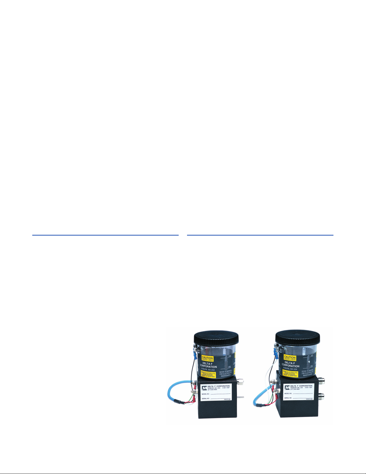
Panametrics Electrolytic
Oxygen Sensor
Nondepleting Oxygen Cell is a
Panametrics product. Panametrics
has joined other GE high-technology
sensing businesses under a new
name_GE Industrial, Sensing.
g
Nondepleting
Oxygen Cell
Page 2

Nondepleting Oxygen Cell with
Electrolytic Oxygen Sensor
Periodic Replacement and Reconditioning Eliminated
The sensor operates on a simple coulometric process in
which oxygen in the sample gas is reduced in an
electrochemical cell. Unlike conventional electrochemical
oxygen cells, the electrodes in this advanced cell are
nondepleting, so they don’t undergo chemical changes
as oxygen is measured. As a result, periodic cell
replacement or conditioning is not required.
Parts Per Billion Oxygen Measurement
For oxygen measurement in ultrapure gas applications,
an ultralow range sensor that is sensitive to less than
five ppb is available. The sensor is equipped with VCR
fittings to ensure system cleanliness and integrity.
Withstands Acid Gases
For most applications where acid gas constituents are
present, the patented STAB-EL™ electrolyte option
eliminates the need for troublesome gas scrubbing
equipment by permitting direct exposure of the cell to
the gas stream. These cells have a reputation for
reliability in applications that are too difficult for most
other oxygen sensors.
Sensor Placement
The basic sensor is available separately. However, for
Type 4 applications requiring indoor/outdoor water- and
dust-tight enclosures, an R4 sensor is available that is
housed in a weatherproof enclosure with integral
mounting flanges. For hazardous (classified) locations,
an R7 sensor is available. It is housed in an
explosion-proof, aluminum electrical box that is rated for
hydrogen service, and can be used in Class I,
Groups B,C&D; Class II, Groups E,F&G; and Class III,
hazardous locations.
GE
Sensing
Page 3

Overall
Type
Nondepleting electrolytic oxygen sensing cell
Available Cells
ppbv O2Range
• L: 0 to 500 ppbv/5 ppmv/50 ppmv
• Ranges for each cell are software selectable in
Panametrics analyzers
ppmv O2Ranges
• A: 0 to 1/10/100 ppmv
• B: 0 to 10/100/1,000 ppmv
• C: 0 to 100/1,000/10,000 ppmv
• D: 0 to 50/500/5000 ppmv
• Ranges for each cell are software selectable in
Panametrics analyzers
Percent O2Ranges
• A: 0% to 5%
• B: 0% to 10%
• C: 0% to 25%
Accuracy
• ±1% full scale (FS) (ranges > 0 to 2.5 ppmv)
• ±5% FS (ranges < 0 to 2.5 ppmv)
Sensitivity
Less than 5 ppb (0 to 500 ppbv range)
Response Time
• Sensor responds instantaneously to O2change
• Equilibrium time is application specific
Ambient Temperature
32°F to 120.02°F (0°C to 49°C)
Nondepleting
Oxygen Cell
Specifications
Background Gas Compatibility
• Standard cell: Ultrapure inert gases
• STAB-EL® cell: All gas compositions including those
containing “acid” gases such as CO2, H2S, Cl2, NOx,
SO2, etc.
STAB-EL® option required for all gases except
ultrapurified gases to pure gas processes.
Max
GE
Sensing
Min
Max
Min
1.62 in
(41.1 mm)
1.23 in
(31.2 mm)
2.05 in
(52.1 mm)
1.31 in
(33.3 mm)
0.37 in
(9.4 mm)
See note
Left View
Front View
2.78 in
(70.6 mm)
Electrolyte
level
window
Electrolyte
reservoir
Sample
gas inlet
1/8 in tube
fitting
Sample
gas outlet
1/8 in tube
fitting
1.05 in
(26.7 mm)
0.52 in
(13.2 mm)
5.88 in
(149.4 mm)
Secondary
positive
electrode
terminal (+)
Secondary
negative
electrode
terminal (_)
4.91 in (124.7 mm)
Primary sensing
positive (+)
electrode
Primary sensing
negative (_)
electrode
Right View
Bottom View
0.5 in
(12.7 mm)
0.25 in
(6.35 mm)
1.5 in
(38.1 mm)
0.62 in
(15.8 mm)
Reservoir fill cap
(also used for
draining of top
draining cells)
This dimension is dependent upon the oxygen range
of the sensor used and varies as follows:
Range Dimension in (mm)
5,000 ppm 2.74 (69.6)
1% 2.85 (72.4)
25% 2.98 (75.7)
2.5%, 5%, 10% 3.10 (78.7)
Nondepleting oxygen cell dimensions
Page 4

g
©2005 GE Infrastructure Sensing. Inc. All rights reserved.
920-014B
All specifications are subject to change for product improvement without notice.
Moisture Image
®
, Moisture Monitor™ are registered trademarks or trademarks of
GE. GE
®
is a registered trademark of General Electric Co. Other company or
product names mentioned in this document may be trademarks or registered
trademarks of their respective companies, which are not affiliated with GE.
R7 oxygen sensor cell (Type 7)
Hazardous Area Classification
• Intrinsically safe when connected to a GE’s
Panametrics Moisture Series analyzer (rack-, bench- or
panel-mount Series 1, 2 or 3 with serial no. 2001 or
above) in accordance with the user’s manual. The
oxygen cell connection to the analyzer must comply
with IP20 protection requirements.
• II 1 G EEx ia IIC T5
–4°F to +122°F (–20°C to +50°C)
• BAS01ATEX1098X
European Compliance
Complies with EMC Directive 89/336/EEC when
connected to a Moisture Image® Series 1, Moisture
Image® Series 2 or Moisture Monitor™ Series 3 analyzer
Sample Requirements
Inlet Pressure
• Less than –0.5 psig (-0.03 barg) (use compressor)
• -0.5 psig to 0.2 psig (-0.034 barg to 0.013 barg)
(use pump)
• 0.2 psig to 1.0 psig (0.013 barg to 0.06 barg)
(standard range)
• 1.0 psig to 60 psig (0.06 barg to 4.13 barg)
(use valve or regulator)
• 60 psig (4.13 barg) (use pressure regulator)
Flow Rate
0.5 to 1.5 L/min
Moisture
No limits (avoid condensation)
Oil/Solvent Mist
• Less than 0.5 mg/ft3(standard range)
• Greater than 0.5 mg/ft3(use filter)
Solid Particles
• Less than 2.0 mg/ft3(standard range)
• Greater than 2.0 mg/ft3(use filter)
R4 FRP oxygen sensor cell (Type 4)
6 in
(152 mm)
1/4 in (8 mm) tube fitting
Max
www.gesensing.com
GE
Sensing
8.5 in
(216 mm)
10.94 in
(277.8 mm)
10.5 in
(266.7 mm)
Min
3 in
(76.2 mm)
Access for
electrical
connections
3 in
(76.2 mm)
5.25 in
(133.4 mm)
Top View
Access for
fluid addition
1.75 in
(44.4 mm)
1.75 in
(44.4 mm)
9 in
(228.6 mm)
10.25 in
(260.4 mm)
Ø 0.44 in
(11.2 mm)
8.5 in
(215.9 mm)
9.75 in
(247.6 mm)
0.625 in
(15.8 mm)
8.38 in
(212.7 mm)
11 in (279.4 mm)
Access for
fluid addition
Sample
gas outlet
1/4 in NPTF
Sample
gas inlet
1/4 in NPTF
Side View Front View (face cover removed)
 Loading...