

Page 1
GV-Control Center
User's Manual V3.6.0
CCV36-A
Page 2
© 2019 GeoVision, Inc. All rights reserved.
Under the copyright laws, this manual may not be copied, in whole or in part, without the
written consent of GeoVision.
Every effort has been made to ensure that the information in this manual is accurate.
GeoVision, Inc. makes no expressed or implied warranty of any kind and assumes no
responsibility for errors or omissions. No liability is assumed for incidental or consequential
damages arising from the use of the information or products contained herein. Features and
specifications are subject to change without notice.
GeoVision, Inc.
9F, No. 246, Sec. 1, Neihu Rd.,
Neihu District, Taipei, Taiwan
Tel: +886-2-8797-8377
Fax: +886-2-8797-8335
http://www.geovision.com.tw
Trademarks used in this manual: GeoVision, the GeoVision logo and GV series products are
trademarks of GeoVision, Inc.
July 2019
Page 3

Contents
Naming and Definition ........................................................................................................ v
GDPR Practice ..................................................................................................................... v
GPU Decoding Specifications ............................................................................................vi
Chapter 1 Introduction ...................................................................................................... 1
1.1 Minimum System Requirements ................................................................................. 2
1.1.1 Software License ................................................................................................................. 3
1.1.2 Supported GeoVision IP Devices and Software .................................................................. 3
1.2 Options ....................................................................................................................... 4
1.3 Overview..................................................................................................................... 5
1.3.1 The Control Center Main Window ....................................................................................... 5
1.3.2 The Toolbar .......................................................................................................................... 6
1.3.3 The Host List ....................................................................................................................... 8
1.3.4 The Group List ..................................................................................................................... 9
Chapter 2 Getting Started ................................................................................................10
2.1 Installation .................................................................................................................10
2.2 Hosts and Groups ...................................................................................................... 11
2.2.1 Creating a Host ................................................................................................................. 12
2.2.2 Creating a Group ............................................................................................................... 13
2.3 Connecting to Control Center.....................................................................................14
2.3.1 The Control Center Server Window .................................................................................. 15
2.3.2 Advanced Settings ............................................................................................................. 16
Chapter 3 Live Video ........................................................................................................18
3.1 Live View ...................................................................................................................18
3.1.1 Displaying Single Live View ............................................................................................... 18
3.1.2 Displaying Multi Views ................................................................................................ 20
3.1.3 Enhancing Live Video ........................................................................................................ 24
3.1.4 Adjusting Distorted Views .................................................................................................. 25
3.2 PIP and PAP View .....................................................................................................26
3.2.1 Starting PIP View ............................................................................................................... 27
3.2.2 Starting PAP View .............................................................................................................. 28
3.3 Panorama View .........................................................................................................29
3.3.1 Creating a Panorama View ................................................................................................ 31
3.3.2 Accessing a Panorama View ............................................................................................. 35
3.3.3 Panorama View Controls ................................................................................................... 35
3.4 VMD Monitoring .........................................................................................................36
3.4.1 Running VMD .................................................................................................................... 36
i
Page 4

ii
3.4.2 The Controls on the Window ............................................................................................. 37
3.4.3 Temperature Alarm ............................................................................................................ 38
3.4.4 Dual-Monitor Display ......................................................................................................... 39
3.4.5 Pop-up Viewer on Another Monitor .................................................................................... 41
Chapter 4 Audio Communication ....................................................................................42
4.1 Audio Communication ................................................................................................42
4.2 Audio Broadcast ........................................................................................................43
4.2.1 Starting the Audio Broadcast ............................................................................................. 43
4.2.2 The Audio Broadcast Window ........................................................................................... 44
Chapter 5 Playback ..........................................................................................................45
5.1 Instant Playback ........................................................................................................45
5.2 Remote Playback .......................................................................................................48
5.2.1 Running the Remote ViewLog ........................................................................................... 48
Chapter 6 Remote DVR Applications ..............................................................................49
6.1 Remote DVR .............................................................................................................49
6.1.1 Running the Remote DVR ................................................................................................. 49
6.2 Remote Desktop ........................................................................................................51
6.2.1 Running Remote Desktop ................................................................................................. 51
6.2.2 File Transfer ....................................................................................................................... 52
6.3 Data Event Query on GV-DVR / NVR .......................................................................53
Chapter 7 I/O Central Panel .............................................................................................55
7.1 Running the I/O Central Panel ...................................................................................55
7.2 The I/O Central Panel ................................................................................................56
7.3 Creating a Group for Cascade Triggers .....................................................................57
7.3.1 Creating a Group ............................................................................................................... 57
7.3.2 Editing a Group .................................................................................................................. 58
7.3.3 Editing an I/O Device ......................................................................................................... 59
7.4 Monitoring Hosts from the I/O Central Panel ..............................................................60
7.5 Configuring the I/O Central Panel ..............................................................................62
7.6 Viewing Connection Log ............................................................................................63
7.7 Setting Up Mode Schedule ........................................................................................64
7.7.1 Creating a Mode ................................................................................................................ 64
7.7.2 Creating a Mode Schedule ................................................................................................ 65
7.8 Quick Link ..................................................................................................................66
7.9 Forcing Output ...........................................................................................................67
7.10 Editing Background Image .......................................................................................68
7.11 Managing a Group of I/O Devices ............................................................................69
7.12 Controlling I/O Devices ............................................................................................70
7.13 Popping Up Live Video upon Input Trigger ...............................................................71
Page 5

iii
Chapter 8 Multi Monitors Applications .....................................................................73
8.1 Application Position ................................................................................................ ...73
8.2 Matrix View ................................................................................................................76
8.2.1 Running the Matrix View .................................................................................................... 77
8.2.2 Live View Enhancement .................................................................................................... 80
8.2.3 Two-Way Audio .................................................................................................................. 80
8.2.4 Instant Playback ................................................................................................................ 81
8.2.5 Channel Display on Another Monitor ................................................................................. 82
8.2.6 Quick Zoom ....................................................................................................................... 83
8.2.7 Configuring the Matrix Position .......................................................................................... 84
8.2.8 POS Live View ................................................................................................................... 85
8.2.9 Advanced Settings ............................................................................................................. 86
8.3 Video Wall .................................................................................................................87
8.3.1 Setting Up a Video Wall Server ......................................................................................... 89
8.3.2 The Layout List .................................................................................................................. 92
8.3.3 Adding a Server and Configuring the Layout .................................................................... 93
8.3.4 Advanced Layout Settings ................................................................................................. 98
8.3.5 Activating the Channel and Layout .................................................................................. 100
8.3.6 Setting Up a Zoom Window ............................................................................................. 101
8.3.7 Setting Up a Scan Window .............................................................................................. 103
8.3.8 Displaying Remote Monitor, Web Page and Playing Back Videos .................................. 106
8.3.9 Displaying Live View from Remote E-Map ....................................................................... 113
8.3.10 Setting Up a VMD Window ............................................................................................. 114
8.3.11 Remotely Accessing the Video Wall Server .................................................................... 115
8.3.12 Updating the Video Wall Server Version ........................................................................ 116
8.4 Fisheye View ........................................................................................................... 117
8.4.1 Virtual PTZ Tour ............................................................................................................... 120
Chapter 9 Other Applications ................................................................................... 122
9.1 Remote E-Map ........................................................................................................ 122
9.1.1 The E-Map Editor Window ............................................................................................... 124
9.1.2 Creating an E-Map........................................................................................................... 125
9.1.3 E-Map Alerts .................................................................................................................... 127
9.1.4 Setting the Polygonal Area .............................................................................................. 128
9.1.5 Setting up the View Zone................................................................................................. 129
9.1.6 The E-Map Window ......................................................................................................... 130
9.1.7 Configuring the Remote E-Map ....................................................................................... 131
9.1.8 Connecting to GV-ASManager ........................................................................................ 132
9.2 MultiLang Tool for Translated Text ........................................................................... 133
9.3 Batch Functions....................................................................................................... 137
Page 6

iv
9.3.1 Configuring the IP Address ................................................................................... 138
9.3.2 Renaming Devices .............................................................................................. 140
9.3.3 Configuring the NAS ............................................................................................ 141
9.3.4 Viewing the Storage Information ............................................................................ 144
9.3.5 Updating Host Information .................................................................................... 145
9.4 Authentication Center .............................................................................................. 146
9.4.1 Installing the Authentication Center ........................................................................ 146
9.4.2 The Authentication Center Window ........................................................................ 147
9.4.3 Setting Up the Authentication Center ..................................................................... 149
9.4.4 Logging In the GV-Control Center .......................................................................... 152
9.4.5 System Settings .................................................................................................. 154
9.4.6 Backup Settings .................................................................................................. 156
9.5 Authentication Server .............................................................................................. 157
9.6 Multicast Setting ...................................................................................................... 159
Chapter 10 System Configuration ........................................................................... 162
10.1 General Settings .................................................................................................... 162
10.2 Network Settings ................................................................................................... 164
10.3 VMD System Settings............................................................................................ 165
10.4 Remote Desktop Settings ...................................................................................... 166
10.5 Video Wall Settings ............................................................................................... 167
10.6 Authentication Center Settings .............................................................................. 168
10.7 Account Management............................................................................................ 169
10.8 Backing Up System Configurations ....................................................................... 171
Appendix A. GV-USB Dongle Upgrade ................................................................... 172
Dongle Requirements ....................................................................................................................... 172
Upgrading the Black Dongle ............................................................................................................. 172
Appendix B. PTZ Control Using GV-Joystick and/or GV-Keyboard .................. 174
Appendix C. RTSP Streaming ................................................................................... 176
Appendix D. Specifications ....................................................................................... 177
Page 7

v
Naming and Definition
GV--DVR /
NVR
GeoVision Analog and Digital Video Recording Software. The GV-DVR also
refers to GV-Multicam System, GV-NVR System, GV-DVR System and
GV-Hybrid DVR System at the same time.
GV-VMS
GeoVision Video Management System for IP cameras.
GDPR Practice
For details on how GeoVision Inc. is committed to helping users become GDPR (General
Data Protection Regulation) compliant, visit the GDPR Consent Request.
Page 8
vi
GPU Decoding Specifications
On-board VGA: GPU decoding is only supported when using the following Intel chipsets:
For H.264 Video Compression
• 2nd Generation Intel Core i3 / i5 / i7 Desktop Processors (Sandy Bridge) - only support
1 MP to 2 MP videos
• 3rd Generation Intel Core i3 / i5 / i7 Desktop Processors (Ivy Bridge)
• 4th Generation Intel Core i3 / i5 / i7 Desktop Processors (Haswell / Haswell Refresh)
• 6th Generation Intel Core i3 / i5 / i7 Desktop Processors (Skylake)
• 7
th
Generation Intel Core i3 / i5 / i7 Desktop Processors (Kaby lake)
For H.265 Video Compression
• 6th Generation Intel Core i3 / i5 / i7 Desktop Processors (Skylake)
• 7
th
Generation Intel Core i3 / i5 / i7 Desktop Processors (Kaby lake)
External VGA: GPU decoding is only supported when using NVIDIA graphics cards with
compute capability 5.0 or above and memory 2 GB or above. To look up the commute
capability of the NVIDIA graphics cards, refer to: https://developer.nvidia.com/cuda-gpus.
Note:
1. Only one external NVIDIA graphics card can be supported by GV-Control Center V3.6 to
perform GPU decoding for free of charge.
2. GeForce GTX1060 is not supported.
On-board VGA + External VGA: To have both the on-board VGA and external VGA
performed GPU decoding, the VGAs must follow their respective specifications listed above.
Note: If you have both on-board VGA and external VGA installed, the on-board VGA must be
connected to a monitor for H.264 / H.265 GPU decoding to be enabled.
For GV-Control Center and GV-Video Wall V3.1.1 or later, GPU (Graphics Processing
Unit) decoding is added to lower the CPU loading and to increase the maximum frame rate.
GPU decoding can be performed on on-board VGA, external VGA, or both, under the
following specifications.
Page 9
vii
Software Specifications for H.264 and H.265
Sandy Bridge
Ivy Bridge / Haswell /
Haswell Refresh / Skylake
/ External VGA (NVIDIA)
Skylake
Kaby Lake
Operating
System
64-Bit
Windows 10
Resolution
1 MP / 2 MP
1 MP / 2 MP / 3 MP / 4 MP /
5 MP / 8 MP / 12 MP
1 MP / 2 MP / 3 MP /
4 MP / 5 MP
Codec
H.264
H.265
GPU decoding is only supported under the following operating system, resolution, and
codec.
Windows 8 / 8.1 / 10 / Server 2008 R2 / Server 2012 R2
Page 10

1
Chapter 1 Introduction
Control Center is a central monitoring station solution (CMS) that provides the CMS operator
with these major features:
Picture-in-Picture and Picture-and-Picture views (See 3.2 PIP and PAP View)
Panorama View (See 3.3 Panorama View)
Pop-up video alerts upon motion detection, input trigger, critical temperature and many
more (See 3.4 VMD Monitoring)
Instant Playback (See 5.1 Instant Playback)
Remote playback (See 5.2 Remote Playback)
Access to client DVRs (See 6.1 Remote DVR)
Access the desktop of a host GV-DVR / NVR / VMS and the operating system (See 6.2
Remote Desktop)
Central management for I/O devices from different hosts (See Chapter 7 I/O Central
Panel)
Display of up to 96 cameras from different hosts on the same screen (See 8.2 Matrix
View)
Video Wall (See 8.3 Video Wall)
Access to the desktop of Video Wall server (See 8.3.9 Remotely Accessing the Video
Wall Server)
Remote E-Map (See 9.1 Remote E-Map)
Support for 31 languages on the user interface
Control Center also supports GV-IP Devices (GV–Video Server, GV-Compact DVR, and
GV-IPCam) and GV-Recording Server or GV-Video Gateway for central monitoring.
Page 11
2
1.1 Minimum System Requirements
OS
64-bit
CPU
Core i7 2600K, 3.4 GHz
RAM
16 GB Dual Channels
Hard Disk
1 GB
Graphic Card
Please see the GPU Decoding Specifications above.
DirectX
9.0c
LAN Card
Gigabit Ethernet x 2
Hardware
Internal or External GV-USB Dongle
Note:
1. We do not recommend installing GV-Control Center and GV-Center V2 Pro on the same
PC. Running GV-Control Center and GV-Center V2 Pro on the same PC may result in
CPU overload error or system failure.
2. To display a megapixel IP channel across monitors, make sure the external graphic
cards on a server are of the same brand, model and driver version, and the capacity of
graphic cards are of NVIDIA GTS 450 or higher to ensure maximum efficiency.
3. When you find CPU usage is high or live view is unsmooth (dropping frames), you may
need to increase the CPU thread and memory, or decrease the number of connected
cameras to improve the system performance.
4. For Control Center to support up to 8 Matrix views with 768 cameras at a time, the
minimum CPU and memory requirements are Core i7 3770 and 16 GB dual channels
respectively.
Before installation, make sure your computer meets the following requirements.
Windows 8 / 8.1 / 10 / Server 2008 R2 / Server 2012 R2
Page 12

3
1
1.1.1 Software License
Free License
N/A
Maximum License
Unlimited
Increment for each license
N/A
Optional Combinations
1. Control Center
2. Control Center + Video Wall (1 to 200 license)
3. Control Center + Vital Sign Monitor
4. Control Center + Vital Sign Monitor + Video Wall (1 to
200 license)
Dongle Type
Internal or external
Note:
1. For Video Wall, make sure you insert a GV-USB dongle with Video Wall function to
Control Center server.
2. It is recommended to use the internal GV-USB dongle to have Hardware Watchdog
which restarts the PC when Windows crashes or freezes.
Introduction
1.1.2 Supported GeoVision IP Devices and Software
⚫ GV-DVR / NVR (V8.5 or later)
⚫ GV-VMS (V14.1 or later)
⚫ GV-ASManager (V4.3 or later)
⚫ GV-SNVR0400F / 1600 (FW V1.1 or later); GV-SNVR0411 (FW V2.0 or later);
GV-SNVR0812 (FW V1.03 or later); GV-SNVR1611 (FW V3.03 or later); GV-SNVR0412
⚫ GV-VS11 / 12 / 14 / 2400 / 2420 / 2800 / 2820 (FW V1.01 or later)
⚫ GV-VS2401 / VS21600
Page 13
4
1.2 Options
Device
Description
GV-Keyboard V3
GV-Keyboard V3 can be used to operate PTZ camera, Matrix View,
ViewLog and Video Wall.
GV-Joystick V2
GV-Joystick can be used in conjunction with GV-Keyboard V3 to
control PTZ channels from GV-Control Centers.
GV-IO Box Series
GV-IO Box series (4E / 4 Ports / 8 Ports / 16 Ports) provide 4 / 8 / 16
inputs and relay outputs and support both DC and AC output
voltages, with optional support for Ethernet module and 4E
additionally supporting PoE, TCP/IP and RS-485 connection.
Internal GV-USB
Dongle
Internal GV-USB Dongle provides the hardware watchdog function to
restart the PC when Windows crashes.
Optional devices can be purchased to assist your surveillance management.
Page 14
Introduction
5
1
1.3 Overview
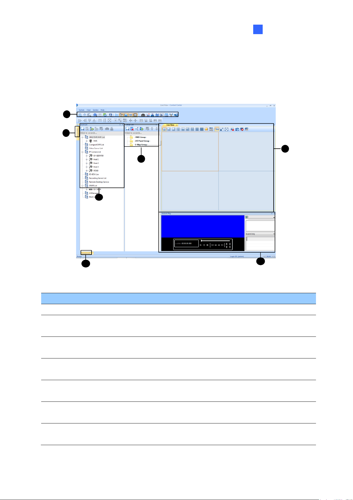
1.3.1 The Control Center Main Window
1
4
5
6
3
2
7
Figure 1-1
No.
Name
Description
1
Toolbar
See 1.3.2 The Toolbar later.
2
Host List
Displays hosts and its channels in a tree diagram. See 1.3.3 The Host
List.
3
Group List
Displays hosts in Groups of VMD, I/O and E-Map. See 1.3.4 The Group
List.
4
Live View
Displays images from the hosts. Drag and drop the cameras from the
Host List for live view display. See 3.1.2 Displaying Multi Views.
5
Layout List
Click the tab to switch to the Layout List. The Layout List contains layouts
for Video Wall. See 8.3.2 The Layout List.
6
Instant Play
Displays the Instant Play window on the main window for playback. See
5.1 Instant Playback.
7
Disconnect
Click View on the main window and select Disconnected List to display
the disconnected cameras from live view, Matrix View and Video Wall.
Page 15
6
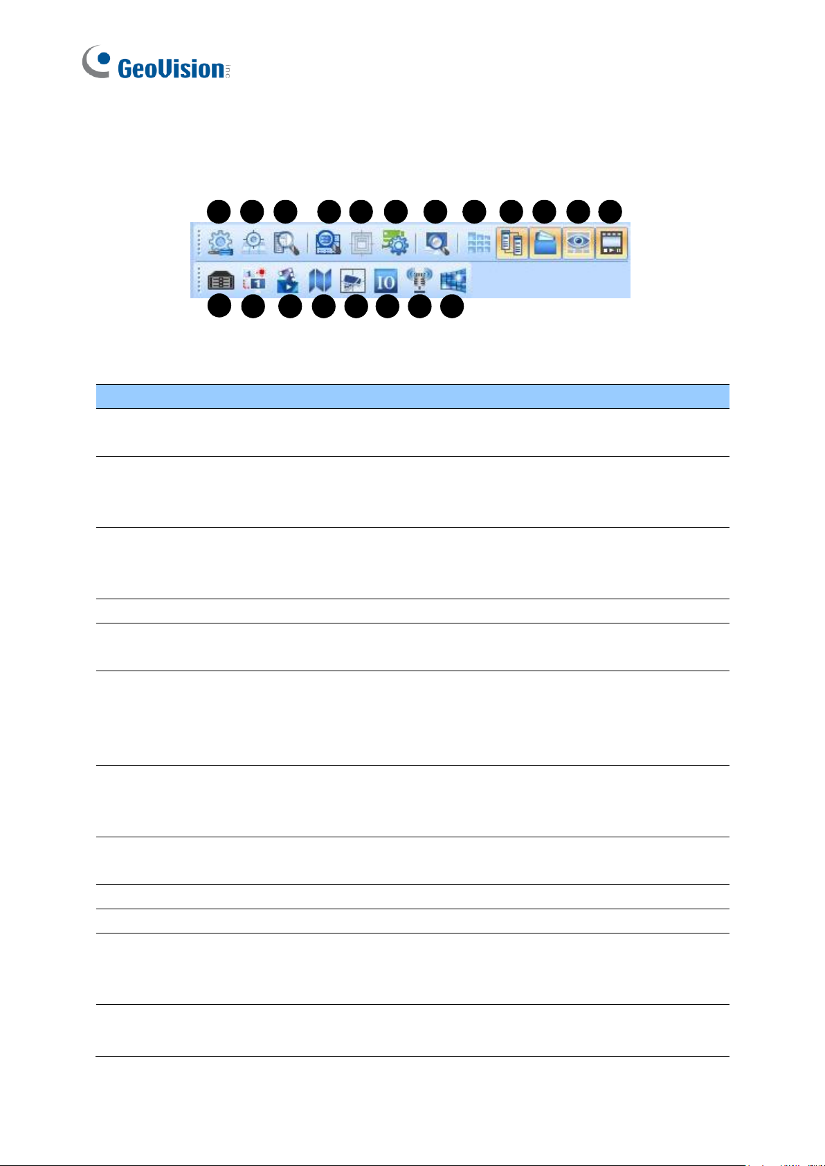
1.3.2 The Toolbar
1
2 3 4 5 6 7 8 9
10 11 12
13
14 15 16 17 18 19
20
No.
Name
Description
1.
Configure
Displays system settings including general settings, network settings,
VMD settings, Remote Desktop and Video Wall.
2.
Application
Position
Configures position and resolutions of application windows, including
GV-DVR / NVR / VMS, Remote ViewLog, Remote E-Map, I/O Central
Panel, and up to 8 matrices. See 8.1 Application Position.
3.
Search Host
Opens the Search Host window, with which you can detect and add
devices of the same LAN to the Host List and select a network card if
you have installed more than one.
4.
Search Server
Searches for Video Wall servers. See 8.3 Video Wall.
5.
Open Activated
Layout
Opens the activated layout on the Control Center’s main window. See
8.3 Video Wall.
6.
Batch Update
Wizard
Manages mass number of GV-IP Devices with integrated interface.
You can change/assign IP address, rename devices, assign NAS and
view storage space information of multiple GV-IP Devices. See 9.4
Batch Functions.
7.
Search Server
Searches for any remote servers with Remote Desktop service
activated. See Displaying a Remote Monitor on Video Wall, 8.3.7
Displaying Remote Monitor, Web Page and Playing Back Videos.
8.
Layout List
Displays the Video Wall Layout List on the main window. See 8.3.2
The Layout List.
9.
Host List
Displays Host List on the main window.
10.
Group List
Displays the Group List on the main window.
11.
Live View
Window
Displays live views collectively on the main window. Drag and drop
cameras for live view display. For more detail, see 3.1.2 Displaying
Multi-Views.
12.
Instant Play
Displays the Instant Play window on the main window. See 5.1 Instant
Playback.
Figure 1-2
Page 16

Introduction
7
1
No.
Name
Description
13.
Remote DVR
Allows the Control Center to access a remote client GV-DVR / NVR.
See 6.1 Remote DVR.
14.
Remote DVR
Desktop
Allows the Control Center to access the desktop of a host GV-DVR /
NVR and the operating system. See 6.2 Remote Desktop.
15.
Remote ViewLog
Allows the Control Center to access the event files of different hosts
and play them back. See 5.2 Remote ViewLog.
16.
Remote E-Map
Allows you to monitor client DVR and GV-IP Devices on E-Maps. See
9.1 Remote E-Map.
17.
VMD System
Displays pop-up live views when a motion, input or temperature alert
is detected. See 3.4 VMD Monitoring.
18.
I/O Central Panel
Collectively manages I/O devices of different hosts. See I/O Central
Panel, Chapter 7.
19.
Broadcast Service
Speaks to multiple hosts over LAN or the Internet simultaneously. See
4.2 Audio Broadcast.
20.
Matrix Quick
Zoom
Displays a selected camera view on the primary monitor when
multiple monitors are used. For Matrix View, see 8.2 Matrix View.
Page 17
8
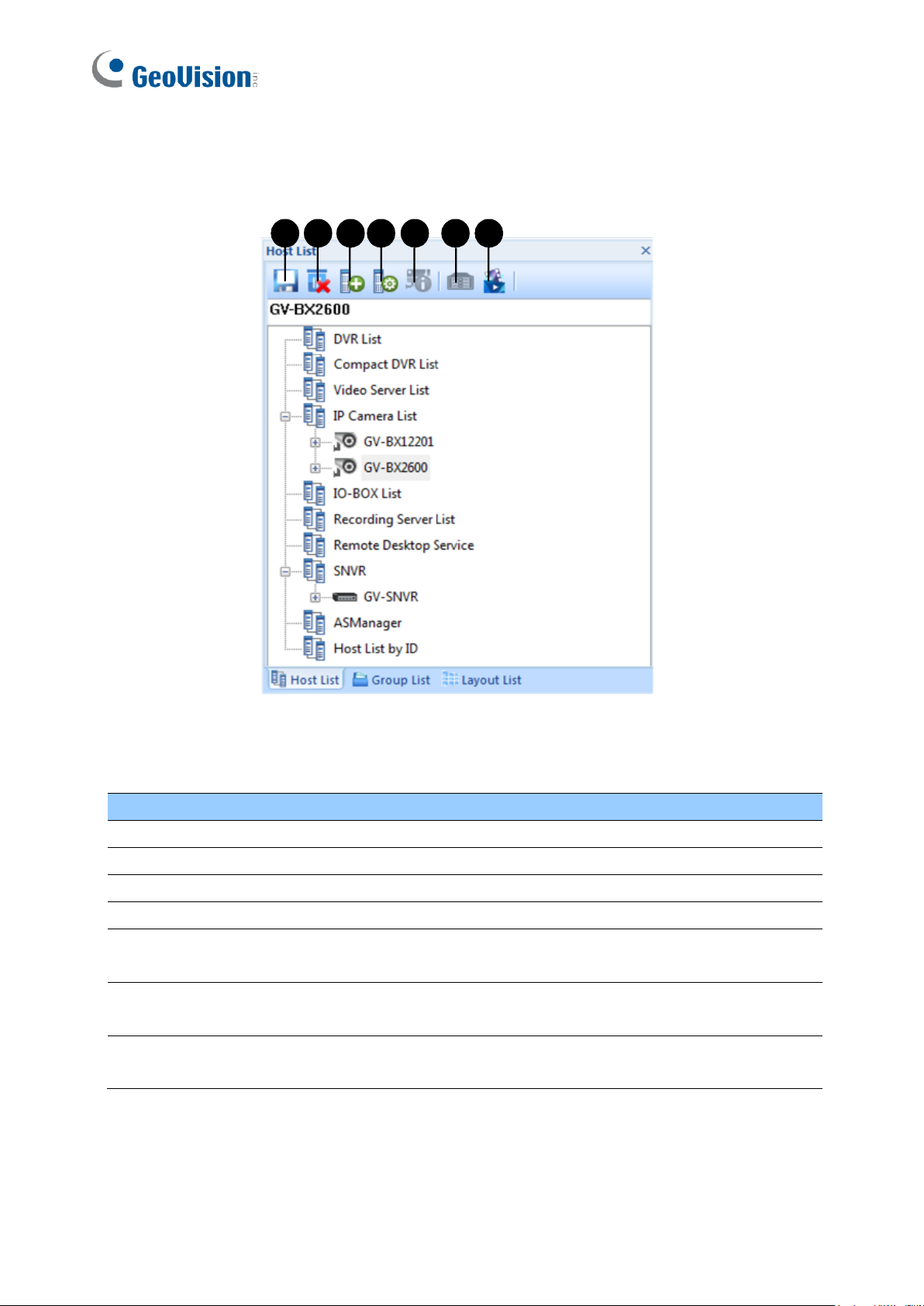
1.3.3 The Host List
1 2 3 4 5 6 7
No.
Name
Description
1
Save
Saves the changes made in Host List.
2
Delete
Deletes the selected host.
3
Add Host
Adds a Host.
4
Host Settings
Displays the host settings of the selected host.
5
Camera
Information
Click to watch live view, access Remote ViewLog and play back
recordings instantly.
6
Remote
Control
Access applications including Remote DVR, Remote Desktop and Event
Data Query. See Remote DVR Applications, Chapter 6.
7
Remote
ViewLog
Plays back recordings of the selected camera. See 5.2 Remote ViewLog.
The controls on the Host List:
Figure 1-3
Page 18
9
1
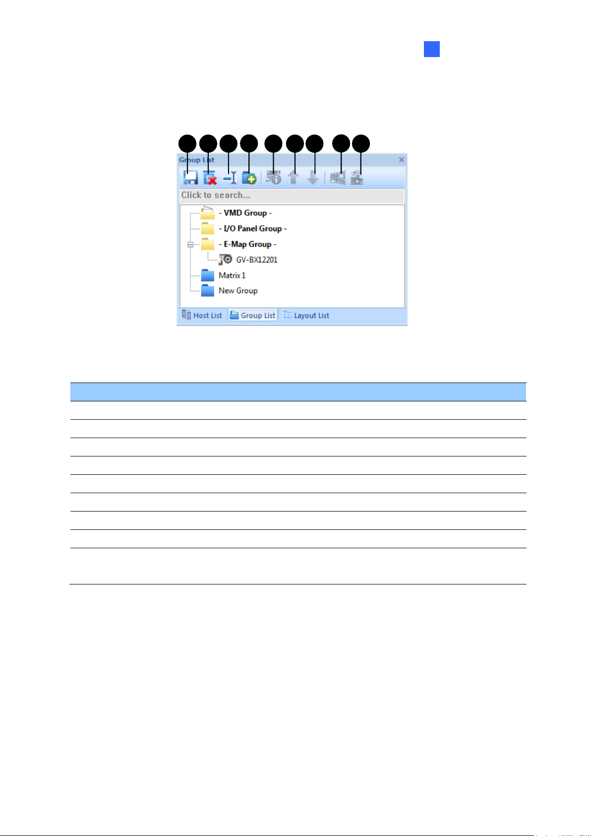
1.3.4 The Group List
1
4
32 5 6 7
8
9
No.
Name
Description
1
Save
Saves the changes made in Group List.
2
Delete
Deletes the selected group.
3
Rename Group
Renames the selected group.
4
Add Group
Adds a new group under the selected category.
5
Camera Information
Looks up device information and access its live view.
6
Move up
Moves the selected camera up in its group.
7
Move down
Moves the selected camera down in its group.
8
Matrix
Displays matrix view. See 8.2 Matrix View.
9
Remote ViewLog
Plays back recordings of the selected camera. See 5.2 Remote
ViewLog.
Introduction
The buttons on the Group List:
Figure 1-4
Page 19

10
Chapter 2 Getting Started
IMPORTANT: By default, the GV-Control Center contains an Administrator account with the
Login ID admin and no password. To change the password or create another account, see
10.7 Account Management.
2.1 Installation
Follow the steps below to install GV-Control Center from the Software DVD or GeoVision
Website.
Installing from Software DVD
1. Plug in the GV-USB Dongle to the computer.
2. Insert the Software DVD to your computer. It runs automatically and a window appears.
3. To install the USB device driver, select Install or Remove GeoVision GV-Series Driver
and follow the on-screen instructions.
4. To install GV-Control Center, select Install GeoVision GV-Control Center and click Yes
to accept the License Agreement.
5. Click GeoVision Control Center and follow the on-screen instructions.
Downloading from GeoVision Website
1. Plug in the GV-USB Dongle to the computer.
2. Go to the Download page of GeoVision Website
3. To install the USB device driver, select Driver, F/W, Patch from the drop-down list to
download the driver.
4. To install GV-Control Center, select Primary Applications from the drop-down list to
download the software.
Page 20

Getting Started
11
2
Note:
1. To use the Search Host function to locate GV devices, it is required to open TCP port
5201 on the client DVR, TCP port 5202 on the Video Server and Compact DVR, and
UDP port 5200 on the Control Center.
2. If antivirus software is installed, the Search Host function may be interfered and will not
detect the available hosts. In this case, turn off the antivirus software and try again.
2.2 Hosts and Groups
You need to create hosts and groups before starting the services. To create hosts, you can
use the Search Host function (No. 3, Figure 1-2) to detect GV devices and
compatible third-party IP devices on the same LAN and add them to the Host List, or you can
follow the steps in the following section.
Page 21
12
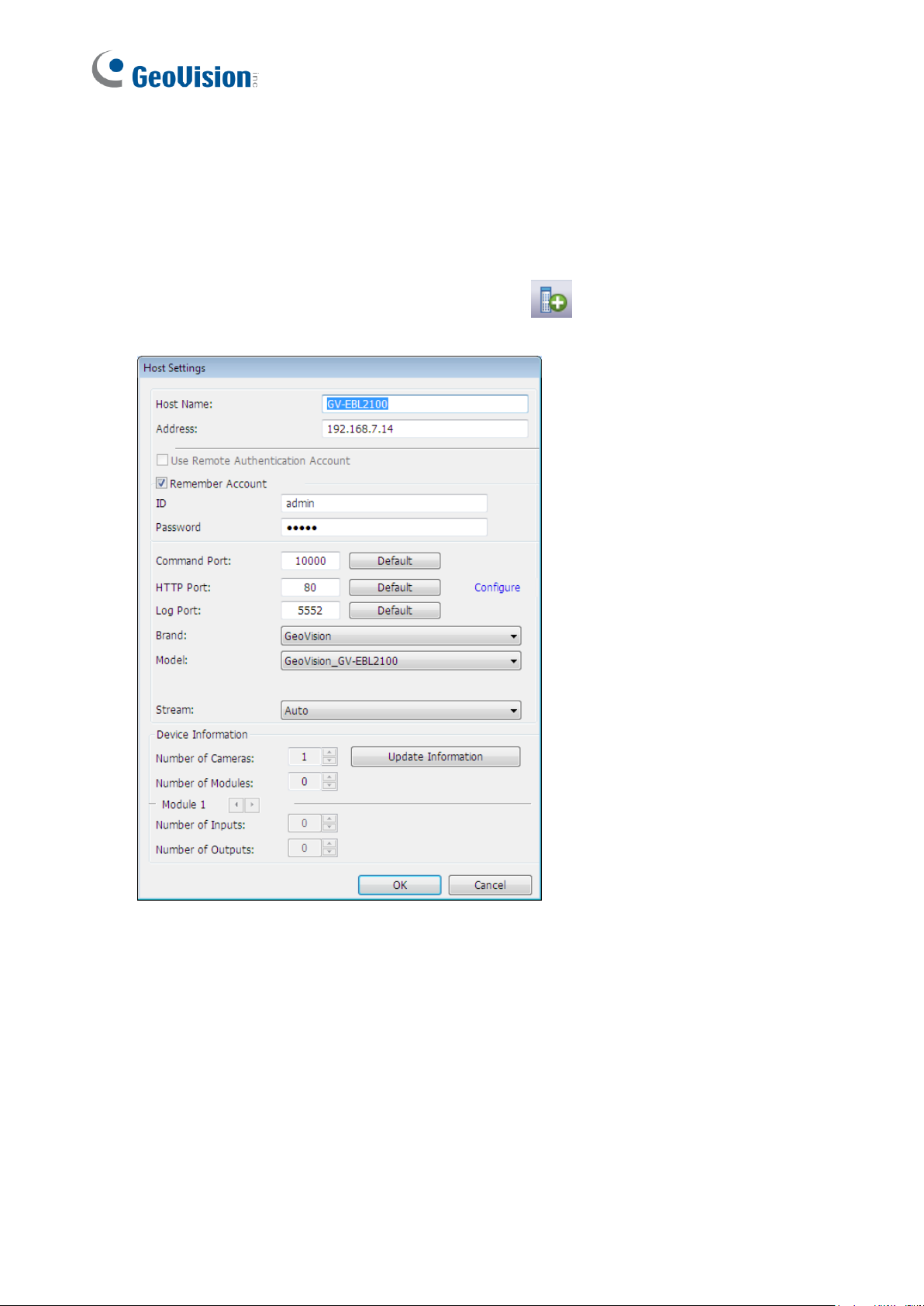
2.2.1 Creating a Host
You can create a host of the DVR, Compact DVR, Video Server, IP Camera, I/O Box and
Recording Server. The Host Settings dialog box may look different among these devices.
The following steps are an example of adding an IP camera host.
1. On the Host List window, click the Add Host button (No. 3, Figure 1-3) and select
Add IP Camera. This dialog box appears.
Figure 2-1
2. Type the host name, IP address, login ID and password of the host. Keep the
communication port as default, unless otherwise necessary.
3. Click the Update Information button to request the number of cameras, I/O modules and
streams of the host. When the update is complete, the message Update system
information successfully appears.
4. Optionally select Stream 1 or Stream 2 for live view display. By default, the Stream
setting is Auto and the received streaming is based on the streaming setting of the
connected IP camera.
5. Click OK to add the host.
Page 22
Getting Started
13
2
Tip:
1. To access the Web interface of the IP device, click Configure on the Host Settings
dialog box (Figure 2-1).
2. To access live view of a camera, right-click the camera on the Host List and select Live
View.
Note:
1. To add a DVR host, it is required to enable Control Center Service at the DVR;
otherwise the message Unable to Connect will appear when accessing the live view.
See 2.3 Connecting to Control Center.
2. The Control Center supports IP video devices using RTSP, ONVIF and PSIA standards.
To connect the IP device compatible with any of these standards, select Protocol from
the Brand drop-down list. See RTSP Streaming, Appendix C.
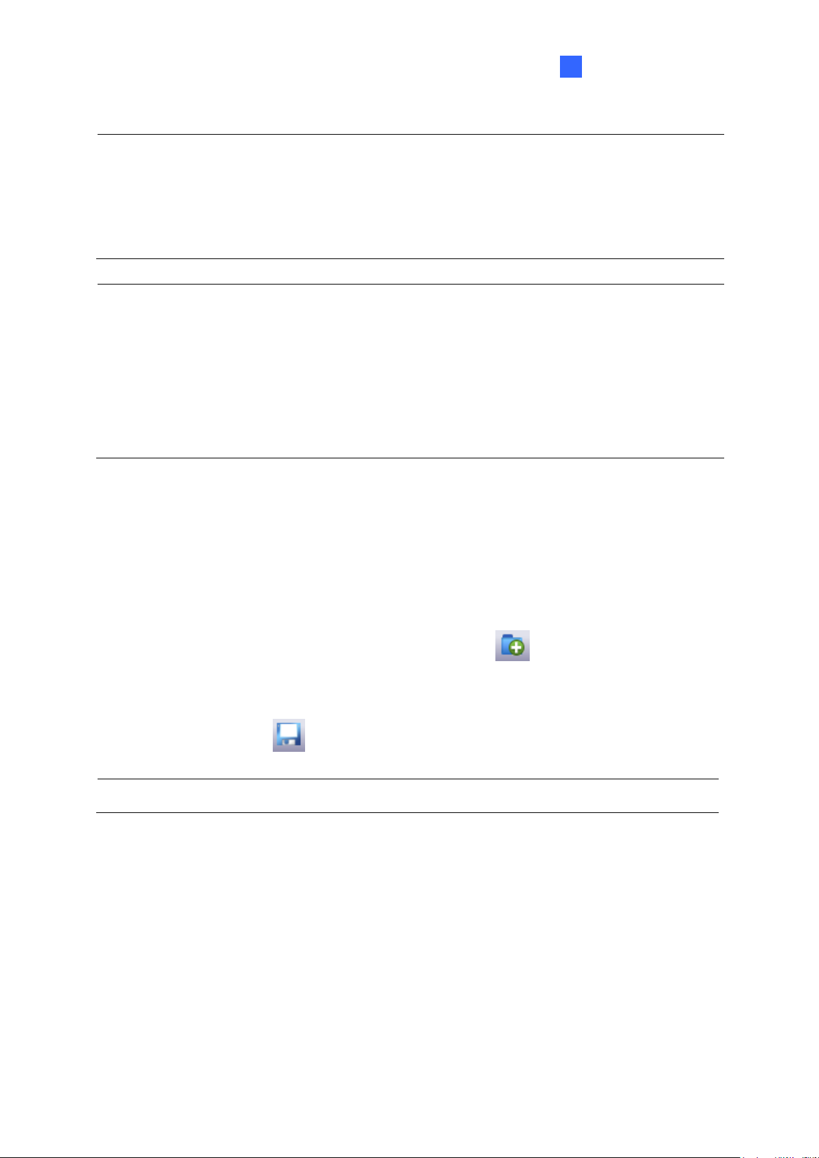
2.2.2 Creating a Group
You can group cameras from different hosts by location and purpose (such as matrix view
display).
1. On the Group List window, click the Add Group button (No. 4, Figure 1-4).
2. Name the created group.
3. Drag the desired cameras from the Host List to the created group.
4. Click the Save button (No. 1, Figure 1-4) to store your settings.
Tip: Right-click a camera to see the device information and access the live view.
Page 23
14
2.3 Connecting to Control Center
1 3 4 5 6
7
1
3
4 5
6
2
The Control Center supports several types of hosts. Only the DVR (GV-DVR / NVR / VMS)
hosts need to be configured and started for connection to Control Center.
To configure the client DVR in order to access the Control Center services remotely through
a network connection, click the Network button on the main screen, select Control Center
Server, and select Start Default Service or Start All Service to connect.
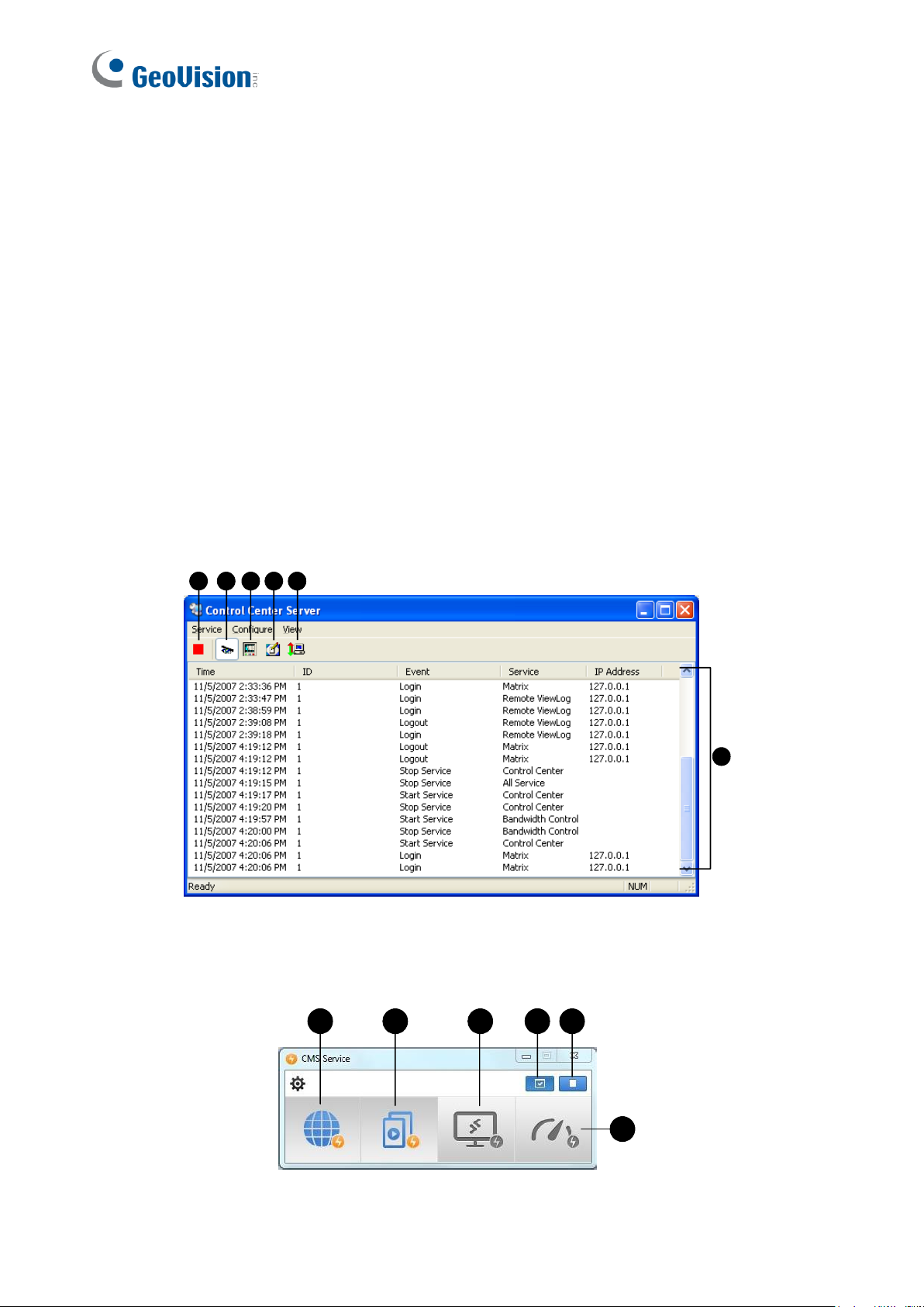
2.3.1 The Control Center Server Window
When the client DVR starts the Control Center Service (CCS) as described above, the server
will be minimized to the system tray. Click the server’s icon to restore its window.
GV-DVR / NVR
GV-VMS
Figure 2-2
Figure 2-3
Page 24

Getting Started
15
2
The controls on the CMS Server:
No.
Name
Description
1
Stop All Service
Stops all Control Center Server services.
2
Start Default Service
Starts all default services.
3
Start / Stop
Control Center Service
Starts or stops these services: Matrix, I/O Central Panel and
Remote DVR. It indicates that the host allows or not allows the
Control Center to access the I/O modules and GV-DVR / NVR /
VMS.
4
Start/Stop Remote
ViewLog Service
Allows or prohibits the Control Center to access the ViewLog
files.
5
Start/Stop Desktop
Service
Allows or prohibits the Control Center to control the desktop.
6
Start / Stop
Bandwidth Control
Service
Allows or prohibits the Bandwidth Control Server to control the
bandwidth. See 11.11 Bandwidth Control Applications,
GV-DVR User’s Manual on the Software DVD.
7
Event List
Indicates login ID, event type, event time, service activation
and IP address.
Note:
1. By default, the live stream images of GV-DVR / NVR / VMS are compressed for better
bandwidth control at the cost of increased CPU usage. The number of remote
connections allowed from the same GV-DVR / NVR / VMS depends on the specs and
the usage of the DVR’s / NVR’s / VMS’ CPU.
2. For GV-VMS V17.1 or later, optionally enable the Substream FIFO function under the
Settings of CMS Server (Figure 2-3) for reduced CPU usage of the GV-VMS and
improved streaming quality at the cost of increased bandwidth. The number of remote
connections allowed from the same GV-VMS depends on the amount of bandwidth
available.
3. To access certain specified streams of a GV-VMS host from multiple CMS servers under
the same LAN, the Multicast function is recommended. For details, see 9.6 Multicast
Setting.
Page 25
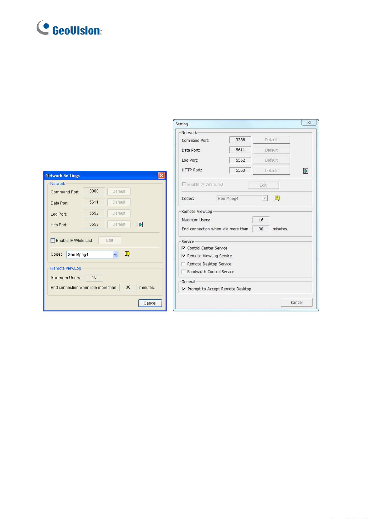
16
2.3.2 Advanced Settings
To configure the CCS Server, click Configure on the window menu.
[Network Settings] Keep the four communication ports as default, unless otherwise
necessary.
Figure 2-4 GV-DVR / NVR Figure 2-5 GV-VMS
◼ Enable IP White List: Limits access to the Control Center Server by assigning IP
ranges.
◼ Codec: Sets video compression to Geo Mpeg4 or Geo H264. Note Remote Desktop
does not support Geo H264 codec.
◼ UPnP: To automatically configure three communication ports on your router, click the
Arrow button beside Http Port for UPnP settings.
◼ Remote ViewLog : Sets the maximum number of users to access the video files for
playback from 1 to 16. It also sets the idle time after which to end the Remote ViewLog
application.
Page 26
Getting Started
17
2
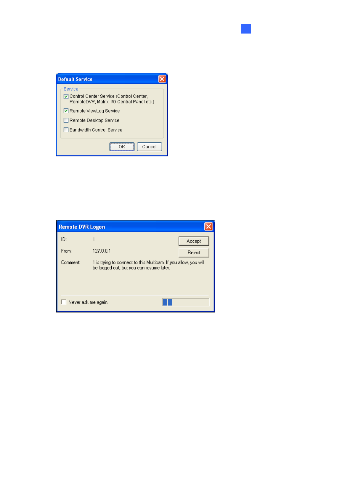
[Event Log Settings] Sets the log storage path and duration.
[Set Default Service] Select the desired services to set as default.
Figure 2-6 GV-DVR / NVR
[Prompt to accept] The client can be prompted to accept or reject the connection when the
Control Center attempts to access its GV-System (through Remote DVR service) or Desktop
(through Remote Desktop).
Figure 2-7 GV-DVR / NVR
[Auto start default service when Windows starts] Automatically runs the default services
at Windows startup.
[Hide when minimized] Hides the minimized Control Center Server window to the system
tray.
Page 27
18
Chapter 3 Live Video
1 2 3 4 5 6 7 8 9
10
3.1 Live View
You can choose to display live views in separate windows or collectively on the Live View
window.
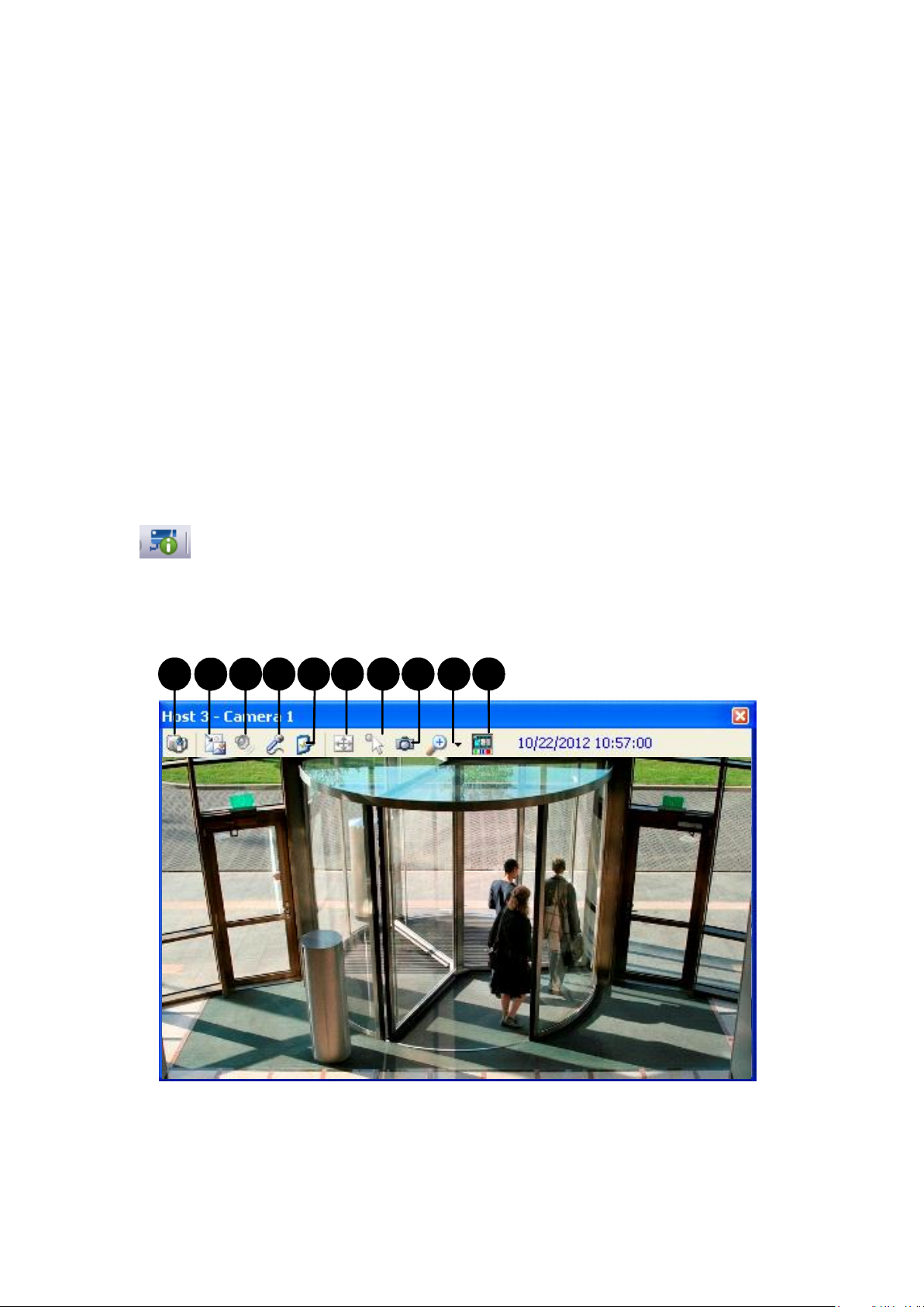
3.1.1 Displaying Single Live View
To display single live view window (Figure 3-1):
On the Host List (Figure 1-3) or Group List (Figure 1-4), right-click any camera and select
Live View.
On the Host List or Group List, select a camera, click the Camera Information button
and select Live View.
On a Remote E-Map window (Figure 9-11), click a camera icon.
Figure 3-1
Page 28

19
3
The controls on the single Live View window:
No.
Name
Description
1
Change
Camera
Switches to another camera of the same host.
2
Change Size
◼ Stream1/Stream2: Changes the size of the live video. The size
corresponds to the video resolution set at the host. The size choices
are only available when the video resolution is higher than 320 x 240.
◼ Defog: Enhances image visibility.
◼ Stabilizer: Stabilizes live images.
◼ PIP View: Refers to Picture in Picture. You can zoom in on the video.
See 3.2 PIP and PAP View.
◼ PAP View: Refers to Picture and Picture. You can create a split video
effect with multiple close-up views on the video. See 3.2 PIP and PAP
View.
◼ Fisheye: Dewarps the fisheye view to quad view.
◼ IMV1 Panomorph: Dewarps the fisheye view. Note this option is only
available for a third-party fisheye camera and when the camera
resolution is set as 1280 x 1024 or higher.
◼ Wide Angle Lens Dewarping: Corrects live view distortions. See
3.1.4 Adjusting Distorted Views.
3
Audio
Receives audio from the host.
4
Microphone
Enables speaking to the host. A microphone must be installed properly in
the computer.
5
Setting
Enables and configures the audio and video settings; Adjusts the image
color (Normalization) and decreases the fogginess of the image (Sampling
Range). Fixes the window to a specific size.
6
PTZ
Activates the PTZ control by selecting PTZ Panel or PTZ Automation.
7
Visual
Automation
Allows you to change the current state of an electronic device, e.g. light
ON, by clicking on its image directly. The function is only available when
the same function is set at the host.
8
Snapshot
Takes the snapshot of the displayed live video.
9
Zoom
Enlarges the video by selecting 1.0x, 2.0x and 3.0x.
10
Instant Play
Plays back the recording in the last 10 seconds, 30 seconds, 1 minute or 5
minutes.
Live Video
Page 29
20
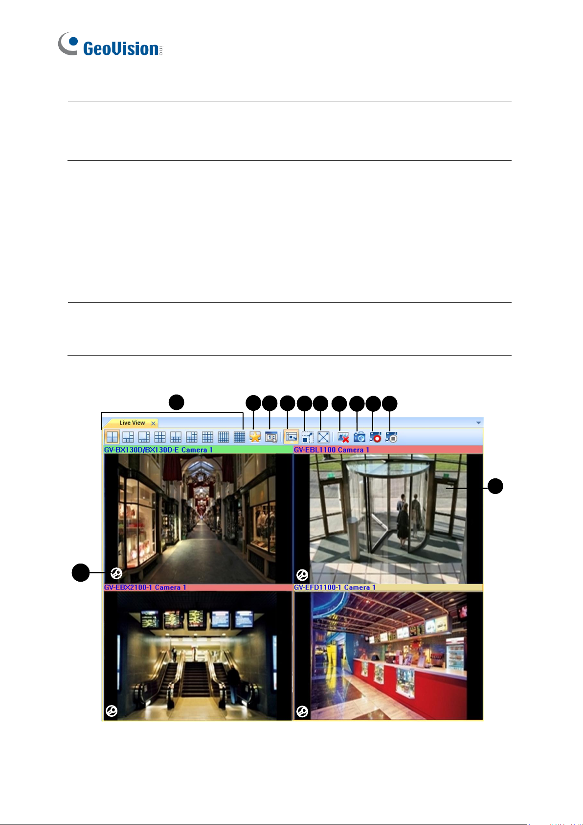
3.1.2 Displaying Multi Views
1
11
3 4
5
6
7 8 9
10
2
12
Note: When the video resolution of the IP camera is larger than the screen resolution of the
Control Center, the maximum live video you can view is approximately half size of that IP
Camera resolution.
Note: For live views enabled from Remote E-Map to display on the Live View window, define
the display position in Application Position window. For detail, see Step 3 in 8.1 Application
Position.
The Live View window is designed for multi-channel live view display. You can monitor up to
36 channels simultaneously. To display live view on this window, you can:
Drag the cameras from the Host List (Figure 1-3) to Live View window (Figure 3-2).
From a Remote E-Map (Figure 9-11), click on a camera icon.
Figure 3-2
Page 30

21
3
The controls on the Live View window:
No.
Name
Description
1.
Screen Division
Select a screen division.
2.
Favorite
Click Set Quad to specify the number of rows and columns in the
live view layout. Click Add to List to save the current layout and
camera assignment to the Favorite list.
3.
Live View Setup
Contains the following settings:
• Full-screen: You can designate a monitor to be used when
you click the full-screen button.
• QView: When there are two or more monitors connected, you
can designate a monitor for QView function if you wish to view
a single-channel live view as full screen on a separate monitor.
• Caption: Select to display the camera name and host name.
• Waveout When Zoomed: Enable audio waveout when a live
view is selected and extended to single view.
• Snapshot Select: Set the storage path for captured
snapshots.
4.
Fit Window
Extends the live view to fill the channel.
5.
Keep Image Ratio
Displays the live view proportionally to its source.
6.
Full Screen
Changes the live view window to full-monitor display.
7.
Close all video
Closes all the live view channels.
8.
Snapshot
Snapshots and saves the live views currently displayed on the
Live View window.
9.
Monitor
Enables monitoring of all the live views.
10.
Stop All Monitoring
Disenables monitoring of all the live views.
11
Monitoring Status
The monitoring status is indicated by the color of the device
name.
For GV-DVR / NVR / VMS / GV-IP Device / GV-Recording Server
hosts (V1.25 or later):
• Red:
A channel from GV-DVR / NVR / VMS V17.1 or later is
being monitored and recorded.
A GV-IP Device / GV-Recording Server host is being
recorded.
• Green: The channel is being monitored but not recorded.
• Yellow: The camera is not monitored nor recorded.
Live Video
Page 31

22
No.
Name
Description
12
If you move the cursor to a live view grid, the icon will appear in
the corner. Click and hold to speak to the surveillance site, or
release the button to listen to the surveillance site.
Page 32

23
3
Right-click the live view to access the following features:
No.
Name
Description
1
Snapshot
Snapshots and saves the live view.
2
Advanced Control
Displays the live view in a separate window. For detail, see
3.1.1 Displaying Single Live View.
3
PTZ
Enables the PTZ function. Note this function is only supported
by IP Cameras that support the PTZ function.
4
Instant Play (5 min)
Plays back the recordings of the last 5 minutes.
5
Face Detection
Adds photos of the persons to be recognized into the Face
Database of a GV face recognition camera. The settings are
similar to those on GV-VMS. See Enrolling Face Data,
Chapter 3, GV-VMS User’s Manual.
5
Audio
Enables Microphone, Wave Out or Two-Way Audio.
6
Face Enroll
Enrolls faces to a GV face recognition camera from the live
images of any connected camera. The settings are similar to
those on GV-VMS. See the Enrolling Face Data from Live
View / ViewLog, Chapter 3, GV-VMS User’s Manual.
7
Show Position
Locates the current host camera on the Host List by highlight.
8
Monitor
Starts or stops monitoring.
9
NAS Setup
Provides a shortcut to the NAS Setup page.
10
Zoom
Displays and extends the current live view to the full Live View
window.
11
VR360
Pans around the 360º image of GV-VR360. Click or
to adjust the speed of the auto pan and click to zoom in.
12
Wide Angle Lens
Dewarping
Corrects image distortion. See 3.1.4 Adjusting Distorted
Views.
13
Wide Angle Lens
Setting
Sets the degree of dewarping to adjust image distortion. See
3.1.4 Adjusting Distorted Views.
1. To view the dewarped images of GV-VR360 on GV-Control Center V3.6 or later, the
graphic card must support DirectX 10.1 or above.
2. Up to 2 GV-VR360 can be connected to a GV-Control Center with a total frame rate of 24
fps. The dewarped images are only supported on Live View and Matrix View.
Live Video
Note for GV-VR360:
Page 33

24
3.1.3 Enhancing Live Video
You can enhance the coloring to have more vivid and saturated images. Click the System on
the main window menu and select DirectDraw Configuration. The Colorful dialog box
appears. Select Use Colorful Model, click OK and restart the Control Center program for
the mode to take effect.
3
Figure 3-3
Page 34

Live Video
25
3
3.1.4 Adjusting Distorted Views
When viewing images through Single Live View, Matrix View or Video Wall, the images may
be curved near the corners. Use the Wide Angle Lens Dewarping feature to correct image
distortion.
1. On the live view, select the Change Size button (No. 2, Figure 3-1) and select Wide
Angle Settings. The Wide Angle Dewarping Setting dialog box appears.
Figure 3-4
2. Move the slider at the bottom to correct the degree of warping. The adjusted view is
shown on the right.
Figure 3-5
3. To apply the configuration, select the Change Size button (No. 2, Figure 3-1) and select
Wide Angle Lens Dewarping.
Page 35

26
3.2 PIP and PAP View
With PIP (Picture in Picture), you can crop your video to get a close-up view or zoom in on
your video. With PAP (Picture and Picture), you can create a split video effect with multiple
close-up views on the video.
You can enable PIP or PAP functions in Live View, Remote ViewLog and Matrix View.
◼ Live View: In the Host or Group List, right-click one camera and select Live View. In the
Live View window, click the Change Size icon and select PIP View or PAP View.
Figure 3-6
◼ Playback: Right-click one camera in the Host List or the Group List, and select Remote
ViewLog. In the Remote ViewLog window, click the View Mode button, select Single
View, and select Mega Pixel (PIP) or Mega Pixel (PAP).
◼ Matrix: Right-click one camera view, and select PIP View or PAP View.
Page 36

Live Video
27
3
3.2.1 Starting PIP View
To start the PIP View, follow the instructions below:
1. After you select PIP View, an inset window of the camera view with a navigation box
appears in the image.
Inset window
Navigation box
Figure 3-7
2. Point the cursor to the inset window. A hand icon appears. You can drag the inset window
to the desired area on the image.
3. Point the cursor to the navigation box. A star icon appears. You can move the navigation
box around in the inset window to have a close-up view of the selected area.
4. To adjust the navigation box size, move the cursor to any of the box corners, enlarge or
diminish the box.
5. To change the frame color of the navigation box, right-click the image, select Mega Pixel
Setting, and select Set Color of Focus Area.
6. To exit the PIP view, click PIP View again.
Page 37

28
3.2.2 Starting PAP View
To start the PAP View, follow the instructions below:
1. After you select PAP View, a row of three inset windows appears on the bottom of the
screen.
Figure 3-8
2. Draw a navigation box on the image, and this selected area is immediately reflected in
one inset window. Up to 7 navigation boxes can be drawn on the image.
3. To adjust a navigation box size, move the cursor to any of the box corners, enlarge or
diminish the box.
4. To move a navigation box to another area on the image, drag it to that area.
5. To change the frame color of the navigation box, right-click the image, select Mega Pixel
Setting and click Set Color of Focus Area.
6. To hide the navigation box on the image, right-click the image, select Mega Pixel Setting
and click Display Focus Area of PAP Mode.
7. To delete a navigation box, right-click the desired box, select Focus Area of PAP Mode
and select Delete.
8. To add another navigation box when less than seven navigation boxes are drawn,
right-click the image, select Mega Pixel Setting, and then select Enable
Add-Focus-Area-Mode.
9. To exit the PAP view, click PAP view again.
Page 38

Live Video
29
3
1
2
3
4
5
6
7
8
9
10
11
12
14
15
13
3.3 Panorama View
Spliced from multiple camera images, a panorama view provides a continuous scene for live
monitoring.
Each camera selected for the panorama view will keep the recording in original format. Up to
4 sets of panorama views can be created.
To access this feature, on the Group List, right-click the desired group, and select Panorama
Setting. The CMS Panorama program is enabled and minimized to the system tray. The
following Panorama Setup dialog box also appears.
Figure 3-9
Page 39

30
The controls on the Panorama View Setup dialog box:
No.
Name
Description
1
Add
Adds an image for automatic splicing.
2
Undo
Cancels the settings.
3
Manual Setting
Manually splices the images together.
4
Blending
Makes the spliced images seamless.
5
Demo
Displays the setup procedure.
6
Left-right location
Changes image addition to the left-or-right option. This function is
only available with the Easy Mode.
7
Top / Bottom
Changes image addition to the top-or-bottom option. This function
is only available with the Easy Mode.
8
Customize resolution
Sets the resolution of the panorama view.
9
Save Before Exit
Saves the created panorama view and closes the dialog box.
10
Exit
Closes the dialog box.
11
Preview Window
Displays the selected source image or the spliced images.
12
Easy Mode
Splices more than two images of the same resolution together. See
Using Images of the Same Resolution in 3.3.1 Creating a
Panorama View.
13
Panorama Selection
Selects the panorama set for the images to be spliced together.
Clicks again to rename the panorama set.
14
Source
Selects the source image to be spliced.
15
Selected Source
Displays the selected image.
Page 40

Live Video
31
3
3.3.1 Creating a Panorama View
To connect camera views with overlapped areas, follow the steps in Using Images with
Overlapped Areas. To connect camera views without overlapped areas and of the same
resolution, follow the steps in Using Images with the Same Resolution.
Using Images with Overlapped Areas
1. Select one panorama set (No. 13, Figure 3-9) from the drop-down list. If you want to
rename the selected panorama set, type the name in the field.
2. Select one camera from the Source drop-down list (No. 14, Figure 3-9) and click the
Add button (No. 1, Figure 3-9).
3. Click Manual Setting (No.3, Figure 3-9). This dialog box appears.
Figure 3-10
4. From the Reference drop-down list, select one camera as the Reference image. At this
step, the camera you selected at Step 2 will be the only Reference image.
5. From the Source drop-down list, select one camera as the Source image to be stitched
with the selected Reference image.
Page 41

32
6. To stitch the two images together, click on a significant point in the Reference image and
Note: For the best result, position the points in the overlapping areas on both images. Avoid
placing the points in a cluster or lining them up straight.
Note: The resolution of the images to be stitched will be reduced to 320 x 240. A panorama
view has a resolution limit of 1920 x 1080. Once the limit is reached, you cannot stitch more
images to the created panorama view.
then look for the same point in the Source image. A dialog box of point selection will
prompt you to confirm. You need to set up 3 points for stitching.
Figure 3-11
7. The resulting image is displayed in the Preview window. If satisfied with the result, click
OK to exit the setup dialog box. If not, re-enter the 3 points for stitching.
8. If you want to stitch a third image or more, click Manual Setting and repeat Steps 3 to 5
multiple times.
9. When you finish stitching images, click the Save Before Exit button (No.9, Figure 3-9) to
save the created panorama view before exiting the Panorama View Setup dialog box.
Using Images of the Same Resolution
To stitch images of the same resolutions and with no overlapping into a panorama view,
follow the steps below.
1. On the Panorama View Setup dialog box (Figure 3-9), select Easy Mode (Video source
must be the same resolution).
2. Select one panorama set from the drop-down list. To rename the selected panorama set,
type the name in the field.
Page 42

Live Video
33
3
3. Select a reference image.
Figure 3-12
A. Select one camera from the Source drop-down list (No. 14, Figure 3-9)
B. Click the Add button (No. 1, Figure 3-9). This image appears in the Preview Window
(No. 11, Figure 3-9).
4. Select an image to be stitched to the reference image.
Figure 3-13
A. Select a camera from the Source drop-down list (No. 14, Figure 3-9).
B. To place the image to the left or right of the reference image, click the Left / Right
button (No. 6, Figure 3-9). To place the image to the top or bottom of the reference
image, click the Top / Bottom button (No. 7, Figure 3-9).
C. Click the Add button (No. 1, Figure 3-9). The Left or right / Top or bottom location
dialog box appears.
Page 43

34
D. Select Left or Right / Top or Bottom to add the image.
Note: You will only be able to add cameras next to the last camera view added. For
example, when adding a third camera, you can only use the direction buttons in
relation to the second camera. You will not be able to go back and select the first camera.
5. To add another image, repeat Step 4.
6. To specify the width and height of the panorama view, click the Customize Resolution
button (No. 8, Figure 3-9), select Enable and type the Width and Height (in pixels).
Figure 3-14
7. When you finish stitching images, click the Save Before Exit button (No.9, Figure 3-9) to
save the created panorama view before exiting the Panorama View Setup dialog box.
Page 44

Live Video
35
3
3.3.2 Accessing a Panorama View
There are two ways to access a panorama view:
Right-click the Group that has set a Panorama view, select Panorama View and select
the desired panorama set from the list.
Right-click the CMS Panorama icon on the system tray, select Panorama View, and
select the desired panorama set from the list.
3.3.3 Panorama View Controls
Figure 3-15
Right-click the panorama view to have these options:
◼ Snapshot: Save the current panorama view as an image file.
◼ Blending: Make the two images smoothly blended together. If this is not set, there can
be harsh edges in the panorama.
◼ Refresh Rate: When the panorama view is enabled, the system load will increase.
Change the refresh rate for the panorama images to optimize system performance. The
refresh rate is from Speed 1 (Slow) to Speed 5 (Fast).
Page 45

36
3.4 VMD Monitoring
With the VMD (Video Motion Detection) function, the operator can be alerted with a pop-up
display of live videos when any of the following events occur: Motion, Temperature Alarm,
Input Trigger, Crowd Detection, Advanced Unattended Object Objection, Advanced Scene
Change Detection and Advanced Missing Object Detection.
Note: The VMD feature does not support the third-party IP cameras.
3.4.1 Running VMD
1. Drag the desired cameras from the Host List and drop them to VMD Group in the Group
List.
Figure 3-16
2. To select the event type for a pop-up alert, right-click the VMD Group, select Video
Analysis, and select the type of event that have been configured for this camera at its
host. Note Motion Detection is selected by default.
3. To open the VMD window, click the VMD System icon . When motion or event is
detected within the camera view, the live video will pop up on the VMD window.
Page 46

37
3
3.4.2 The Controls on the Window
1
3 4 5 6
7
2
No.
Name
Description
1
Page Up & Down
Scrolls the page up and down.
2
Refresh
Refreshes the camera view. The feature is unavailable when the
Camera pops up in the user-defined position option is enabled
(Figure 10-3).
3
Select Quad
Sets the screen division.
4
Show System
Menu
Includes these settings:
• Image Quality: Changes the display quality to Best, Normal or
Low.
• Host List: Displays the hosts added to the VMD group in tree
view.
• Pop-up Viewer: Displays a pop-up event on another monitor.
See 3.4.5 Pop-up Viewer on Another Monitor.
• System Configure: Enables DirectX; specifies Dwell Time (the
duration of popup camera view), Minimum Duration (the interval
of each motion and input trigger detection); enables Invoke
Alarm (computer alarm upon each motion detection); defines the
critical temperature.
• Event Popup: Changes the duration that a pop-up view remains
on the screen. By default each popup remains for 60 seconds.
• Sound Scheme: Changes the alarm sound for different events.
5
Minimize
Minimizes the window in Windows taskbar.
6
Exit
Closes the window.
7
Pop-up camera
Right-click the pop-up camera to have these settings:
• Advanced Live View: Opens the live view window for further
control. See 3.1 Live View.
• Instant Playback: See 5.1 Instant Playback.
Live Video
Figure 3-17
Page 47

38
3.4.3 Temperature Alarm
Note:
1. The critical temperature refers to the interior temperature of the device, but not its
operating temperature.
2. This feature is only supported by GV-DVR with GV-3008 Card and certain GV-IP
Cameras. For the support list, refer to the GV-IPCAM User’s Manual for detail.
You can set up a temperature alarm by specifying a critical temperature, upon or beyond
which the live view will pop up on the VMD window.
1. On the VMD window, click the Show System Menu icon on the top right corner and
select System Configure. The System Configure dialog box appears.
2. Type Critical Internal Temperature.
Figure 3-18
3. Right-click the camera under the VMD Group, select Video Analysis and select
Temperature Alarm.
4. The live view should pop up on the VMD window when the camera’s temperature
reaches or exceeds the specified critical temperature.
Page 48

Live Video
39
3
3.4.4 Dual-Monitor Display
You can set up two monitors to display the VMD windows for pop-up displays.
Note: For monitor resolution of 1280 x 1024 and above, up to 42 pop-up views can be
displayed on a VMD window. For monitor resolution lower than 1280 x 1024, up to 36
pop-up views can be displayed on a VMD window.
To set two monitors to display the VMD windows:
1. On the main window, select System, select Configure and click the VMD System tab.
Figure 3-19
2. In the Position section, select the monitor to be the first VMD window (Monitor 1) and the
second Vital Sign Monitor window (Monitor 2). Click OK.
3. To open the VMD window, click the VMD System button on the Group List.
4. To set the screen division for both Monitor 1 and Monitor 2, click the Select Quad button
on the VMD window and select a screen division.
Figure 3-20
Page 49

40
5. When the first monitor is full of the pop-up camera view, the next pop-up camera view will
21
3 4
5
Monitor 1
Monitor 2
1
2
Monitor 1
Monitor 2
go to the second monitor.
Applications of two VMD windows:
The position of pop-up cameras on the VMD windows varies when you enable or disable the
Camera pops up in the user-defined position option in Figure 10-3.
⚫ When the option is disabled: When multiple pop-up alerts are triggered simultaneously,
the positions of pop-up views on the VMD windows are based on the sequence order of
motion or event detection. When the first monitor is full of pop-up views, the next pop-up
view will go to the second monitor.
Example:
Both Monitor 1 and Monitor 2 are set at 4 screen divisions. When 5 pop-up alerts are
triggered simultaneously, the first 4 pop-up views will appear on Monitor 1 and the last
pop-up view will appear on Monitor 2.
⚫ When the option is enabled: The positions of pop-up views on the VMD windows are
based on the camera sequence in the VMD Group.
Example:
In the VMD Group, Camera A is listed as the third camera and Camera B is the fifth. Both
monitor 1 and monitor 2 are set at 4 screen divisions. When the pop-up alerts from the
two cameras are triggered simultaneously, Camera A images will appear on the third
square of Monitor 1 and Camera B images will appear on the first square of Monitor 2.
Note the order of pop-up views is from left to right on the VMD window.
Page 50

Live Video
41
3
3.4.5 Pop-up Viewer on Another Monitor
With the Pop-up Viewer feature, you can define the duration that a pop-up view stays on
another monitor. The pop-up view on the VMD window will be closed as soon as motion
stops or an event is undetected.
When motion or an event is detected, the camera view will pop up on the primary monitor
and the assigned monitor together. When motion or an event is undetectable, the pop-up
view on the primary monitor will close, but the pop-up view on the other monitor will last for
the specified time. The last image of the pop-up view will remain on the screen if no new
event pops up. To clear the image, right-click on the screen and select Clear.
Note: For this function to work, the Control Center must be set up with at least two monitors.
1. Click the Show System Menu button on the toolbar of VMD window, and select Pop-up
Viewer. This dialog box appears.
Figure 3-21
2. Use the drop-down list to select a desired monitor.
3. Type Play Time to specify the length of time that a pop-up view remains on another
monitor. Type the time length between 1 and 10 seconds.
Page 51

42
Chapter 4 Audio Communication
4.1 Audio Communication
The Control Center operator can speak to, listen to and engage in two-way communication
with a specified host.
Speaking and Listening to a Camera
There are two ways of enabling audio from cameras:
1. Move the cursor to the live view grid and click at the left bottom corner.
2. Right-click the live view, click Audio, select Microphone and select Wave Out / 2 Way.
Speaking and Listening to a client GV-VMS
1. Right-click the client GV-VMS from the Host List, select Microphone and type the ID and
Password of the client GV-VMS.
2. Select 2 Way so you can speak and listen to the GV-VMS with microphone and speaker.
Page 52

Audio Communication
43
4
Note: The Audio Broadcast function supports both GV and third-party IP devices with
speaker functions.
Tip: To add hosts by dragging, click the Setup button and select Always on top to
keep the Audio Broadcast window to be on top of other windows.
4.2 Audio Broadcast
The Control Center operator can use the Audio Broadcast function to speak to multiple hosts
at one time.
4.2.1 Starting the Audio Broadcast
1. To open the Audio Broadcast window, click the Broadcast Service button on the
Toolbar. This dialog box appears.
Figure 4-2
2. Right-click the host and select Add to Broadcast Service or drag the desired hosts from
the Host List to the Audio Broadcast window.
3. You can mark or unmark the hosts on the Audio Broadcast window to enable or disable
audio broadcasting to them.
4. To start audio broadcasting to the hosts, click the Start/Stop Broadcasting button
on the Audio Broadcast window, and talk to the microphone connected to the computer of
Control Center.
Page 53

44
4.2.2 The Audio Broadcast Window
1
2
3
4
5
6
7
8
Figure 4-3
The controls on the Audio Broadcast window:
No.
Name
Description
1
Host Name
Displays the host name.
2
IP
Displays the host IP address.
3
Status
Displays the connection status of the host.
4
Change Style
Minimizes or enlarges the Audio Broadcast window.
5
Close
Closes the Audio Broadcast window.
6
Setup
◼ Always on top: Always displays the Audio Broadcast window on
top of the screen.
◼ Opacity: Select the opacity level for the Audio Broadcast
window. The value can range from 20% (fully transparent) to
100% (fully opaque).
7
Start/Stop
Broadcasting
Starts or stops audio broadcasting.
8
Dragging Area
Click the button and drag the Audio Broadcast window to the desired
position.
Page 54

Playback
45
5
Chapter 5 Playback
5.1 Instant Playback
You can retrieve and play back recordings from DVR, GV-IP Device, GV-Recording Server
and GV-SNVR System.
Note: Playback for GV-Recording Server is only supported for V1.230 or later.
The following function must be enabled ahead to allow remote access from the Control
Center:
• DVR: Enable recording and Remote ViewLog Service (No. 4, Figure 2-2).
• GV-IP Devices: Enable recording and ViewLog Server.
1. To start instant playback:
• In the Host List (Figure 1-3) or Group List (Figure 1-4) , right-click one camera and
select Instant Play (5 Min).
• On the Live View window (Figure 3-2), right-click one camera and select Instant Play
(5 Min).
• In the VMD window, right-click the pop-up camera and select Instant Play (5 Min).
• On the I/O Central Panel (Figure 7-2), click an input icon and select Instant Play or
right-click an input icon, select Information, select an event from the Trigger Time
List and select Instant Play.
• In the Matrix view (Figure 8-5), click on the Camera Name, select Instant Play and
select the time length.
• On the Remote E-Map (Figure 9-11), click the Host Information button to
display the Host Information dialog box and select an event for playback.
Tip: By default, the event selected from Remote E-Map is played back on the Control
Center’s main window. To play back in a separate Instant Playback window, see 8.1
Application Position for details.
Page 55

46
2. The Instant Play window appears. You can select the camera, date and video events for
Playback scroll
Play
Pause
Stop
Forward
Home
Backward
End
Move to prev 5 min
Move to next 1 min
Move to next 5 min
Move to prev 1 min
Name
Functions
Play Mode
Includes these options:
• Frame by Frame: Plays back video frame by frame.
• Real Time: Plays back video on real time. This mode saves waiting
time for rendering, but drop frames to give the appearance of
real-time playback.
• Key frame: Plays back the key frame of the video.
• Audio: Turns the video sound on or off and reduce noise.
• Play Speed: Plays back the video at a faster or slower speed.
• Auto play next 5 minutes: Plays back video up to 5 minutes.
playback.
Figure 5-1
For further playback features, right-click the Instant Play window. The features vary
based on the selected host.
Page 56

Playback
47
5
Name
Functions
Render
Includes these options:
• Deinterlace: Converts the interlaced video into non-interlaced
video.
• Scaling: Smoothens mosaic squares when enlarging a playback
video, and applies the colorful mode to enhance the coloring.
• Deblocking: Removes the block-like artifacts from low-quality
and highly compressed video.
• Defog: Enhances image visibility.
• Stabilizer: Reduces camera shake.
• Text overlay’s camera name and time: Overlays camera name
and time onto the video.
• Text overlay’s POS/GV-Wiegand: Overlays POS or
GV-Wiegand Capture data onto the video.
• Fisheye: Select Geo Fisheye to choose a camera mode; select
Panomorph to enable a 360 view of a third-party fisheye
camera.
• Mega Pixel View: Enable PIP or PAP view. See 3.2 PIP and PAP
View.
• Wide Angle Lens Dewarping: Corrects image distortion. See
3.1.4 Adjusting Distorted Views.
• Display GPS: Shows the camera’s position on the video.
• Select GPS Map: Selects a map type for GPS display.
• Full Screen: Switches to the full screen view.
Tools
• Snapshot: Saves a video image.
• Save as AVI: Saves a video as avi format.
• Download: Downloads the video clip from the DVR or IP video
device to the local computer.
Note: The Defog and Stabilizer only work when the functions have been applied on the
recording from the DVR.
Page 57

48
5.2 Remote Playback
The Remote ViewLog service allows the Control Center to access the event files of different
hosts and play them back with ViewLog player.
5.2.1 Running the Remote ViewLog
1. For DVR hosts (GV-DVR / NVR / VMS), their Remote ViewLog Service (No. 4, Figure
2-2) must be activated first.
2. At the Control Center, highlight a host in the Host List or a group in the Group List. Then
click the Remote ViewLog button .
When the connection is established, the ViewLog player will appear on the Control Center
desktop. For details on ViewLog, see Chapter 4, GV-VMS User’s Manual.
Page 58

49
Chapter 6 Remote DVR Applications
6.1 Remote DVR
The Remote DVR service allows the Control Center to access client GV-DVR / NVR and
configure their settings remotely. This feature reduces the trips to each client DVR
individually.
Note: The Remote DVR service is not supported by GV-VMS.
6.1.1 Running the Remote DVR
1. The client DVR must activate Control Center Service (No. 3, Figure 2-2) first.
2. At the Control Center, highlight a DVR host on the Host List, click the Remote Control
button and select Remote DVR.
If the connection is established, the main screen of the client DVR will display on the Control
Center desktop. At the same time, the client DVR will display the following message,
advising that the GV-DVR / NVR is in use and has been locked.
Figure 6-1
Page 59

50
If the client wants to interrupt the connection, click the button at the bottom right corner.
Tip: If you wish to minimize the bandwidth used while viewing cameras of the client DVR,
you can choose to view certain cameras only. There are two ways to activate and deactivate
cameras:
1. Before connecting to the client DVR, in the Control Center, click the Application
Position button , right-click the Remote DVR window, and select Activate Remote
Channels to select or unselect cameras.
Figure 6-2
2. When connecting to the client DVR, on the main screen of the client DVR, click the Exit
button, and then select Activate Remote Camera. Check or uncheck cameras.
Note: Currently Remote DVR does not support audio output, PTZ and I/O control.
A valid ID and Password are required to stop the connection.
Page 60

Remote DVR Applications
51
6
Note:
1. You can choose a suitable connection speed. See 10.4 Remote Desktop Settings.
2. The Monitor button is only supported for GV-VMS 15.10.1.0 or later.
6.2 Remote Desktop
The Remote Desktop allows the Control Center operator to access its host DVR and also
control the client desktop in a separate window. The Control Center operator has full control
of the client GV-DVR / NVR / VMS and its operation system.
6.2.1 Running Remote Desktop
1. The client DVR must activate Remote Desktop Service (No. 5, Figure 2-2) first.
2. At the Control Center, highlight a host in the DVR List. Then click the Remote Control
button , and select Remote Desktop.
When the connection is established, the client desktop will appear in a separate window on
the Control Center desktop. If the client DVR is using multiple monitors, you can click the
Monitor icon .
Page 61

52
6.2.2 File Transfer
Note: The size of one single file for transfer cannot exceed 4 GB, but there is no size limit
for multiple files.
The File Transfer function is designed to transfer files easily between the Control Center and
client DVR.
1. Run the Remote Desktop.
2. Click the File Transfer button on the upper left corner of the Remote Desktop. The
File Transfer Service dialog box appears.
3. Select the desired file to transfer to Local (the Control Center) or Remote (the client
DVR).
Figure 6-3
Page 62

Remote DVR Applications
53
6
6.3 Data Event Query on GV-DVR / NVR / VMS
You can query events that occur at DVR hosts by defining search criteria. The search results
can be displayed in text or in chart. You can also export your research results in the form of
text, html or excel.
Query Categoryies
Search Criteria
Search Results Playback WindowVideo Icon
Figure 6-4
1. Enable the WebCam Server.
• On GV-DVR / NVR, click the Network button , select WebCam Server and click
OK.
• On GV-VMS, click Home , click Toolbar , click Network , click WebCam
Server and click OK.
2. On the Control Center, right-click the desired DVR host on the host list, select the
Remote Control button and select Event Data Query. The Event Data window
appears.
3. On the left panel, select a query category and then click Submit Query at the bottom to
display its search criteria.
◼ Monitor: events that are monitored
◼ System: system activities
Page 63

54
◼ Login: user login/logout status
◼ Counter: counter events
◼ POS: POS transaction events
4. Define each search criteria such as Event Type, Device, Information, Date etc. The
search criteria vary depending on the search category selected.
5. If you want to search the events recorded during the Daylight Saving Time period, select
DST Rollback and specify the time period in the Date column.
6. Click Submit Query. The search results will be displayed in text form.
7. To graph the search results, click the Chart button.
8. To play back any attached video, click the Video icon .
9. To export the search results, select the file type using the drop-down list and click
Export.
Page 64

I/O Central Panel
55
7
Chapter 7 I/O Central Panel
The I/O Central Panel provides a centrally managing solution for I/O devices from different
hosts. Its major features are:
Group I/O devices from different hosts
Trigger I/O devices in cascade mode
Monitor different I/O cascade configurations at different times of the day
Provide quick access to triggered I/O devices by a Quick Link window
Note:
1. The Advanced I/O Panel at the client DVR and the I/O Central Panel at the Control
Center can conflict each other. It’s recommended that the client DVR cleans up the
settings in the Advanced I/O Panel and renders the I/O control to the Control Center.
2. The I/O Central Panel only supports GV-IP Devices.
7.1 Running the I/O Central Panel
1. For DVR hosts, the client DVRs must activate Control Center Service (No. 3, Figure 2-2)
first.
2. On the Control Center Toolbar, drag the desired hosts from the Host List to the I/O Panel
Group in the Group List and click the Save button.
Figure 7-1
Page 65

56
3. Click the I/O Central Panel button on the Control Center toolbar.
1 2 3 4 5 6
7
8
9
No.
Name
Description
1
Configure
Accesses Panel and Schedule settings.
2
Mode Schedule
Starts/stops Mode Schedule.
3
Toggle Quick Link
Displays the Quick Link window for quick access to triggered
I/O devices.
4
Advanced I/O List Style
Displays the Advanced I/O List in various styles: View/Edit,
Icon and Detail.
5
Expand Tree Row
Expands tree branches.
6
Collapse Tree Row
Collapses tree branches.
7
Mode
Configures various cascade modes.
8
Standard I/O List
Displays connected I/O modules.
9
Advanced I/O List
Groups I/O devices in cascade mode.
When the connection is established, the I/O Central Panel appears on the Control Center
desktop.
7.2 The I/O Central Panel
The controls on the I/O Central Panel:
Figure 7-2
Page 66

I/O Central Panel
57
7
7.3 Creating a Group for Cascade Triggers
You can group I/O devices by function or geography. Further, the group allows cascade
triggers, meaning that the trigger actions of one trigger can activate another trigger.
For this example, you might have a group called “Entrance” that contains all I/O devices
installed at entrances. The “Entrance” group might contain other sub groups, each of which
contains just the related I/O devices in various geographic locations:
Group containing all I/O devices installed at entrances
Input 2 installed at the front entrance
Output 1 sub group at the kitchen
Output 3 sub group at the garage
Figure 7-3
When Input 2 is triggered, it will trigger Output 1 and Output 3 sub groups, and Output 1 will
trigger Output 2 in a cascade series.
7.3.1 Creating a Group
1. Right-click on Advanced I/O List (No.9, Figure 7-2), and then select Add A Group. This
dialog box appears.
Figure 7-4
[Group Name] Names the group.
[Group Notify Setting]
◼ Invoke Alarm: Invokes the computer alarm upon I/O trigger. Select a sound from the
drop-down list.
2. Click Save to apply the settings, and return to the panel.
3. To create a cascading hierarchy, drag the desired inputs/outputs from the left Standard
I/O List to the group.
Note: In the cascading hierarchy, each input can only be used once while the same output
can be used repeatedly.
Page 67

58
7.3.2 Editing a Group
To modify group settings, right-click a group, and select View/Edit. This dialog box appears.
Figure 7-5
[Group Name] As described in Figure 7-4.
[Group Notify Setting] As described in Figure 7-4.
[Current Pin Setting] To enable this option, highlight an I/O device from the group list at the
bottom.
◼ Trigger Associated Outputs: Triggers outputs in cascade mode. Click the Finger tab to
apply the change to all I/O devices at the same group.
◼ Change Icon: To enable this option, select one of two displayed icons: Normal or Trigger.
Click the Change Icon tab to change an icon. Click the Finger tab to apply the change to
all I/O devices at the same group.
Page 68

I/O Central Panel
59
7
7.3.3 Editing an I/O Device
In addition to editing groups, you can also edit the settings of individual I/O device.
Right-click an I/O device, and select Setting. This dialog box appears.
Figure 7-6
[Display Setting] You can define the nature of I/O devices by colors. Note that the setting
only affects the Detail style of the Advanced I/O List (No. 4, Figure 7-2).
◼ Alarm Level drop-down list: Click the drop-down list, and select one of the six default
colors: Fire, Smog, Vibration, Intruder, Motion and Emergency. For the Level Undefined
option, select Text Color or Background Color, and then click the Input/Output
drop-down list to change its color.
Tip: To modify the naming for default alarm level, see 7.4 Configuring the I/O Central Panel in
the following section.
[Trigger Setting]
◼ Trigger Associated Outputs: Triggers outputs in cascade mode.
◼ Latch Trigger: Instead of a lasting output alarm, the Latch Trigger option provides a
momentary alarm when an input is triggered in cascade mode. For details, see Latch
Trigger, Chapter 6, GV-DVR User’s Manual on the Software DVD.
◼ Associated Camera: Assign a camera for its live view to be popped up when this input
is triggered. After this option is enabled, you can click the input icon and select View
Associate Camera to view live video anytime.
◼ Digital Input Invoke Associated Camera: The live video pops up when its associated
input is triggered. See 7.13 Popping Up Live Video After Input Trigger.
Page 69

60
7.4 Monitoring Hosts from the I/O Central
Panel
You can watch host live view, play back recordings and view host information directly from
the I/O Central Panel. This is especially useful for administrator to get an immediate checkup
of the host when a trigger event occurs.
Figure 7-7
Watching Live View
On the I/O Central Panel, click an input and select View Associated Camera to watch the
live view of the camera associated with this input device. A single Live View window appears.
To associate a camera with the input, see 7.3.3 Editing an I/O Device. For details on single
Live View, see 3.1.1 Displaying Single Live View.
Page 70

I/O Central Panel
61
7
Viewing Host Information
You can obtain information on host name, alarm level and a history of trigger events.
Right-click an input icon from the Advanced I/O List and select Information. The Pin
Information dialog box appears.
Figure 7-8
Playing Back Trigger Events
To play back host recordings, click its associated input from the Advanced I/O List and select
Instant Play. The Instant Playback window appears. For details, see 5.1 Instant Playback.
Alternatively you can select a specific trigger event for playback. Right-click the input icon
from the Advanced I/O List, select Information, select an event from the Trigger Time List
(Figure and select Instant Play.
Note: To allow remote access from Control Center, the following functions must be enabled
ahead:
• DVR: Enable recording and Remote ViewLog Service
• GV-IP Devices: Enable recording and ViewLog Server
Page 71

62
7.5 Configuring the I/O Central Panel
On the panel toolbar, click the Configure button (No.1, Figure 7-2) and select Panel Setting.
This dialog box appears.
Figure 7-9
[Startup]
◼ Show Quick Link: Opens the Quick Link window at panel startup.
◼ Start Schedule Monitoring: Starts Mode Schedule at panel startup. For details, see
7.7Setting up Mode Schedule below.
[Layout]
◼ Show Host Name: Displays the host name of each I/O device on the Advanced I/O List.
◼ Use User-defined Text: Allows you to modify the text of Alarm Level (Figure 7-6).
Page 72

I/O Central Panel
63
7
7.6 Viewing Connection Log
You can view the connection status of the hosts. On the panel toolbar, click the Configure
button (No.1, Figure 7-2) and select View Notification. This dialog box will appear. The
maximum of 1000 messages will be logged for reference.
Figure 7-10
◼ Time: Displays the time of the connection/disconnection.
◼ Message: Displays the connection/disconnection status of the hosts.
Page 73

64
7.7 Setting Up Mode Schedule
The Mode Schedule allows you to monitor surveillance sites using different I/O cascade
configurations according to the scheduled time. For example, you may want I/O cascade
triggers one way during business hours and another way for non-business hours. Modes can
be switched automatically at a scheduled time.
7.7.1 Creating a Mode
1. Click the Mode drop-down list (No. 7, Figure 7-2), and select Mode Edit. This dialog box
appears.
Figure 7-11
2. Click Add, and name the created mode. You can create up to 100 modes.
3. Click Save to return to the panel.
4. Select the created mode from the Mode drop-down list, and create the groups in the
Advanced I/O List. For details, see 7.3 Creating a Group for Cascade Triggers earlier in
this chapter.
Page 74

I/O Central Panel
65
7
7.7.2 Creating a Mode Schedule
Define the times and days you like the panel to switch modes.
1. On the panel toolbar, click the Configure button (No.1, Figure 7-2), and select Schedule
Setting. This dialog box appears.
Figure 7-12
2. Click Add to create a schedule. This dialog box appears.
Figure 7-13
◼ Name: Type a name for the schedule.
◼ Mode: Select a mode from the drop-down list.
◼ Time: Define a time period you want the mode to run.
◼ Days: Check the day box(es) you want the mode to run.
3. Click OK to apply the settings, and click Save to return to the panel.
4. To start the mode schedule, click the Mode Schedule button (No. 2, Figure 7-2), and
then select Mode Schedule Start.
Page 75

66
7.8 Quick Link
The Quick Link provides a quick access to triggered I/O devices. It is a separate window that
displays all the groups established in the Advanced I/O List. The group icon flashes when
any included I/O device is triggered. Clicking the flashing icon will bring you to the I/O
location in the Advanced I/O List.
◼ To open the Quick Link window, click the Toggle Quick Link button. (No. 3, Figure 7-2).
◼ To open the Quick Link window at panel startup, check the Show Quick Link option in
Figure 7-9.
Figure 7-14
Page 76

I/O Central Panel
67
7
7.9 Forcing Output
To manually force an output, click one output, and select Force Output.
◼ In the Standard I/O List, you can force the output individually.
◼ In the Advanced I/O List, considering cascade triggers, you can only manually force the
output at the top level, e.g. Figure 7-15. Outputs at sub levels cannot be forced
manually, e.g. Figure 7-16.
However, if the output is not in a cascading hierarchy, you can definitely force it manually, e.g.
Figure 7-17.
Figure 7-15 Figure 7-16 Figure 7-17
Page 77

68
7.10 Editing Background Image
With the Background Image feature, you can import a floor plan to lay out the locations of
triggered I/O devices. This feature works in the Icon style of the Advanced I/O List.
1. To switch to the Icon style, click the Advanced I/O List Style button (No. 4, Figure 7-2)
and then select Icon.
2. Select a group in the Advanced I/O List. The I/O icons of this group will be displayed.
3. Right-click on the right screen, and select Background Image to import a graphic file.
4. Now you can freely drag the I/O icons to the desired locations on the imported map.
5. To add images to another group, repeat Steps 2 to 4.
Figure 7-18
Page 78

I/O Central Panel
69
7
7.11 Managing a Group of I/O Devices
With groups of I/O devices set up on the Advanced I/O List, you can enable or disable these
I/O devices by groups.
Enabling a Group
On the Advanced I/O List, right-click a desired group and select Start Monitoring. All input
devices of this group are now enabled. When inputs are triggered, outputs will be activated in
cascade mode.
Disabling a Group
On the Advanced I/O List, right-click a desired group and select Stop Monitoring. All input
devices of this group are now disabled. No cascade triggers will occur.
Pausing the Triggered Inputs
This feature is designed for a group of outputs set to be Toggle mode. When inputs activate
outputs in cascade triggers, right-click this group and select Pause Monitoring. The inputs
of the group will be reset, but the outputs keep on alarming.
Page 79

70
7.12 Controlling I/O Devices
Note: This function also supports the client GV-IP Devices of these firmware versions:
GV-Compact DVR: Firmware V1.43 or later
GV-IP Camera: Firmware V1.05 or later
GV-Video Server: Firmware V1.45 or later
The Control Center operator can manually arm or disarm any I/O devices of different hosts
without interrupting the monitoring.
Arming or disarming I/O devices
1. On the Standard I/O List, right-click one host and select I/O Enable Setting. This dialog
box appears.
Figure 7-19
2. Check the Input/Output to arm or uncheck the Input/Output to disarm the device (s).
Then click Apply to verify the changes.
Page 80

I/O Central Panel
71
7
7.13 Popping Up Live Video upon Input
Trigger
You can be alerted by a pop-up live video after an input device is triggered. One input device
can trigger up to 4 cameras and a total of 16 camera views can be accessed on I/O Control
Panel simultaneously.
1. On the toolbar, click the Configure button (No.1, Figure 7-2), select Panel Setting and
click the Notify tab. This dialog box appears.
Figure 7-20
2. By default, the pop-up camera view is displayed in a separate window. Specify the
Maximum Number of Invoked Camera Views that can pup up simultaneously when
input devices are triggered. Up to 16 camera videos can be accessed.
3. Select Enable digital input to invoke the associated camera to activate the function.
4. If you want to pop up the camera view on the VMD window, select VMD Integration
Mode. For this option, you must also enable the VMD window by clicking VMD System
icon (No. 18, Figure 1-2).
Page 81

72
5. To map a camera to an input device, right-click an input device in the Advanced I/O List,
Tip: You can use a GV-Keyboard to switch the audio (microphone and speaker) of the
pop-up video on or off.
and select Setting. This dialog box appears.
Figure 7-21
6. Select Associated Camera and assign up to four cameras from the drop-down list.
7. Select Digital Input Invokes the Associated Camera.
8. Click OK. When the input is triggered, the live video of its associated camera will pop up.
Page 82

73
Chapter 8 Multi Monitors Applications
Note: If the Control Center is displayed on a widescreen monitor, you can also utilize this
feature to help you arrange the positions of multiple application windows.
Tip: Right-click the space at the bottom to sort icons in Icon, List, Tile or Details.
8.1 Application Position
The Application Position is a tool for adjusting the resolution and position of the multiple
application windows in Control Center.
1. Click the Application Position button on toolbar. The Application Position window
appears.
Figure 8-1
Page 83

74
2. Right-click an icon, select Show to display the window on the layout and manually drag
Tip: You can freely move and place a window between or among monitors.
the window to assign position. Alternatively right-click the window/icon, select Set
Position and type co-ordinates.
Figure 8-2
3. To adjust the resolution and access other settings, right-click the application window or
the icon at the bottom.
Figure 8-3
Page 84

Multi Monitors Applications
75
8
◼ Resolution: Select a resolution option.
◼ Show: Uncheck this option to remove the window from the Application Position panel.
◼ Activate Remote Camera: For Remote DVR only. Select or unselect access to
individual channels of client DVR.
◼ Shut down when the Control Center is closed: For I/O Central Panel only. Select to
inactivate the I/O Central Panel when the Control Center is closed.
◼ Always apply specified position: For I/O Central Panel only. Select to always show
the I/O Central Panel at the specified position upon startup.
◼ Full Screen: For Matrix window only.
◼ Set Position: See Step 2 in this section.
4. To configure the view and playback types for Remote E-Map, right-click the Remote
E-Map icon or window:
Figure 8-4
◼ View Type: You can define the display position of live view enabled from the Remote
E-Map.
Remote E-Map: Select this mode for the camera live view to appear in a separate
window (Figure 3-1). This option is selected by default.
Live View: Select this mode for camera live view to appear on Control Center’s
Live View window (Figure 3-2).
Video Wall: Select this mode for camera live view to appear on the Video Wall.
For further details on Video Wall settings, see 8.3.8 Displaying Live View Enabled
from Remote E-Map.
◼ Playback:
Remote E-Map: Select this option to play back recordings in a separate Instant
Playback window.
Control Center: Select this option to play back recordings in the Instant Playback
window on the Control Center’s main window.
5. Re-activate the application for the configurations to apply.
Page 85

76
8.2 Matrix View
Note: For Control Center to support up to 8 Matrix views with 768 cameras at a time, the
minimum CPU and memory requirements are Core i7 3770 and 16 GB dual channels
respectively.
Matrix View allows the center operator to monitor up to 96 cameras from different hosts on
the same screen. Further, the operator can remotely change camera’s monitoring status and
properties. The Matrix view provides these features:
Support for screen resolution of 1024 x 768, 1280 x 1024, 1600 x 1200, 1680 x 1050,
1920 x 1200, 1280 x 800, 1920 x 1080 and 1440 x 900
Simultaneous display of up to 96 cameras
Display of up to 8 Matrix windows in 1 monitor or separate 8 monitors at a time
Support for remote configuration of camera status and properties
Support for Camera Scan, PTZ Control and POS Live View functions
Access to client ViewLog for playback
Page 86

Multi Monitors Applications
77
8
8.2.1 Running the Matrix View
1. For DVR hosts, the client DVRs must activate Control Center Service (No.3, Figure 2-2)
first.
2. At the Control Center, highlight a Group and click the Matrix button . The Matrix
window appears.
Tip:
1. To add or replace one camera view in a Matrix view, make sure you have set the
Control Center window position to be always on top and simply drag the desired
camera from the Group List to the desired channel position. See 10.1 General Settings.
Note that when Matrix is closed and opened next time, the dragged cameras will not be
displayed.
2. You can set the access right to a group folder. By default, only Administrator and Power
User accounts have the right to configure the access to a group folder. To allow for
access, log in an Administrator account, right-click a group folder, select Matrix
Privilege Setting, select User or Power User and select accounts to allow for access
to this folder.
Figure 8-5
Page 87

78
09 SHOW10 Camera 4
11 SHOW10 Camera 8
03 TEST56 Camera 402 TEST56 Camera 3
07 SHOW10 Camera 6
16 TEST56 Camera 6
1 2 3 4 5 6
7
8 9
Figure 8-6
No.
Name
Description
1
Exit
Closes or minimizes the Matrix window.
2
Screen Division
Select screen divisions with the choices of 1, 4, 6, 8, 9, 12, 16,
20, 24, 32, 36, 48, 64, 80 or 96 channels.
3
Date/Time
Indicates the current date and time.
4
Monitor
Starts or stops monitoring.
5
Configure
Access the Matrix settings and camera properties.
6
ViewLog
Opens ViewLog player.
7
Camera Scan
Rotates through screen divisions.
8
PTZ
Displays the PTZ control panel. To display the PTZ control
panel, you can also right-click the connected channel and select
PTZ Control.
The controls on the Matrix window:
Page 88

Multi Monitors Applications
79
8
No.
Name
Description
9
Monitoring Status
Monitoring status is indicated by the color of the device name
(not supported with GV-Recording Server).
• Red:
A channel from GV-DVR / NVR / VMS is being
monitored and recorded.
A GV-IP Device / GV-Recording Server / GV-SNVR
host is being recorded.
• Green: The channel is being monitored but not recorded.
• Yellow: The camera is not monitored nor recorded.
Tip: To enable monitoring, right-click a channel and select Start Monitoring. The device
name bar of the monitored channels change to red when these cameras are being
recorded.
Note:
1. To display Matrix views in separate 8 monitors, make sure your computer is equipped
with enough VGA cards. To set up multiple monitor positions and resolutions, see 8.1
Application Position.
2. The Matrix supports megapixel resolution only on a single screen. Click the button
at left-top corner of the single screen to display megapixel images.
3. According to your screen divisions, the Matrix will reduce the received resolution as
close to the division size as possible. For GV-IP Devices, the JPEG stream of 704 x 480
or smaller will be changed to the MPEG stream of the similar size; the JPEG stream
higher than 704 x 480 will remain as JPEG stream. The mechanism is designed to
reduce CPU usage and save bandwidth.
Page 89

80
8.2.2 Live View Enhancement
Enhancing Live Images
You can enhance the coloring to have more vivid and saturated images. This function is
enabled by default. Click the Configure button (No. 5, Figure 8-6), select System Configure,
select Enable DirectDraw, click OK and restart the Control Center program for the mode to
take effect.
Adjusting Distorted Views
Images may be curved especially near the corners. To correct image distortions, right-click
the channel you want to adjust for distortion and select Wide Angle Lens Settings. The
Wide Angle Dewarping Setting dialog appears. For details, see 3.1.4 Adjusting Distorted
Views.
8.2.3 Two-Way Audio
The Two-Way Audio feature allows the operator to speak to and listen from the selected host.
This is especially useful when suspicious events occur and the operator would like to
communicate with the security personnel at the surveillance site. To access this feature,
right-click on a camera view that you wish to communicate with, and select Wave out Toggle
to access audio from the host and Talk Back Toggle to speak to the host.
Figure 8-7
Page 90

Multi Monitors Applications
81
8
8.2.4 Instant Playback
When monitoring through Matrix View, you can instantly play back any suspicious videos of a
certain time length. Time length choices include 10 seconds, 30 seconds, 1 minute and 5
minutes. For details see 5.1 Instant Playback.
To instantly play back the events of all channels, click the ViewLog button (No.6, Figure
8-6), select Instant Play, and select the time length.
To instantly play back the event(s) of a single channel, right-click the camera on the
device tree on the Control Center window and select Instant Play (5 min.).
Page 91

82
8.2.5 Channel Display on Another Monitor
The selected channel is displayed
on another monitor screen.
Select a channel to be displayed
on another monitor screen.
If the Control Center is equipped with multiple monitors, you can use the QView feature to
display a selected channel on another monitor screen.
1. Open the Matrix window, click the Configure button (No. 5, Figure 8-6), and select
QView. This dialog box appears.
Figure 8-8
2. Use the drop-down list to select a desired monitor.
3. Click one channel to be displayed on that monitor.
4. To switch to another channel, simply click another channel in the Matrix.
Figure 8-9
Page 92

Multi Monitors Applications
83
8
8.2.6 Quick Zoom
When you are monitoring Matrix Views on multiple monitors, the Quick Zoom feature allows
you to call back a desired camera view to display on the primary monitor for instant
inspection.
1. Click the Matrix Quick Zoom button (No. 21, Figure 1-2). This dialog box
appears.
Figure 8-10
2. To identify the position numbers of monitors, click the Identify button. The position
numbers will be displayed on the Matrix Views. Following is an example of running four
Matrix Views in four separate monitors.
Figure 8-11
3. To display a desired camera view on the primary monitor, type its monitor number of the
Matrix View and the camera channel. Click Zoom.
4. To return to the previous Matrix View settings, click Restore.
5. To disable the position numbers displayed on Matrix Views, click Identify again.
Page 93

84
8.2.7 Configuring the Matrix Position
Note: To automatically display Matrix views at Control Center startup, and set up the
display order, see 10.1 General Settings. The folder turns red when it is assigned with a
startup position.
When you have set up more than one monitor and want to display matrices separately on
each of the monitors, you can assign a monitor to each of the matrix groups.
1. Configure the matrix position using the Application Position button (No. 2, Figure
1-2). For details, see 8.3 Application Position.
2. Right-click a Matrix group, select Set Start Position and select a matrix number. The
matrix numbers here correspond to the ones on Application Position layout. A “P” letter
appears on the group folder once the position is assigned.
Figure 8-12
Page 94

Multi Monitors Applications
85
8
8.2.8 POS Live View
The POS Live View allows you to view POS transaction data or cardholder information of
access control in a separate window.
Note: This function is only supported by GV-DVR / NVR / VMS.
To open the POS Live View window, click the ViewLog button (No. 6, Figure 8-6) and
select POS Live View.
To have the instant playback, double-click the desired transaction item or cardholder data
on the POS Live View window.
Figure 8-13
For details on POS Live View on GV-DVR / NVR, see POS Live View, Chapter 7, GV-DVR
User’s Manual.
For details on POS Live View on GV-VMS, see Point-Of-Sale (POS) Application, Chapter 10,
GV-VMS User’s Manual.
Page 95

86
8.2.9 Advanced Settings
On the Matrix window, click the Configure button (No. 5, Figure 8-6).
Figure 8-14
◼ Caption: Displays the ID, Location or Camera Name stamp on screen.
◼ Camera Scan: Sets the rotation interval between cameras. Click the Arrow button to set
rotation mode of 1, 4, 6, 9, 16 or 24 channels. You can also enable the automatic scan
function at the Matrix startup.
◼ DirectX: Sets the DirectDraw function.
◼ PTZ Control: Select one type of PTZ control panel. For details on PTZ Automation, see
PTZ Automation, Chapter 1, GV-DVR User’s Manual on the Software DVD.
◼ View: If your video sources or connections tend to be interrupted, or if you want to
prevent the operator from knowing about a broken connection, select this option and set
the duration for the last frame to remain on the screen when connections are lost.
[Camera Configure] Adjusts the properties and recording settings of cameras from DVR /
NVR hosts.
[Video Attributes] Adjusts video attributes of cameras.
[Image Quality] Adjusts the video quality with the choices of Best, Normal and Low. The
better quality will result in bigger image size and need bigger bandwidth.
[QView] Allows you to display channels on another monitor. For details, see 8.2.5 Channel
Display on Another Monitor.
[Full Screen] Extends the channels to full screen. Press the Esc key to return to the original
mode.
[Auto Retry when Connection Broken] Automatically reconnects when the connection
between the Matrix View and cameras is lost. This option is enabled by default.
Page 96

Multi Monitors Applications
87
8
8.3 Video Wall
A Video Wall is an establishment of multiple monitors on a server, displaying composite IP
sources from various IP devices. Using the Control Center, you can remotely configure and
manage up to 200 Video Walls, each with a different layout. On each Video Wall, you can:
display up to 288 IP channels
freely adjust the size and position of each channel, whether it be within or across
monitors
create up to 16 Zoom Windows, which display channels through manual activation
create up to 16 Scan Windows, which are capable of displaying up to 64 channels in turn,
at customizable time interval
display up to 16 web pages using Web Window
play back up to 16 videos using Media Window
play back up to 16 videos using Remote ViewLog Window
display live views enabled from Remote E-Map
display live views in up to 16 screen divisions upon motion detection using the VMD
Window
display up to 288 channels of customized view region of a remote monitor
From Control Center, you can:
access and configure the settings of Video Wall server
Figure 8-15
Page 97

88
Note:
1. A GV-USB dongle with Video Wall function is required to connect to the Control Center.
2. The number of monitors allowed depends on the capability of the Video Wall server’s
graphic card.
3. For the minimum system requirements of a Video Wall server, see 1.1 Minimum
System Requirements.
An application of the Video Wall
Vital Sign Monitor
(Control Center + Video Wall + Vital Sign Monitor)
With the appropriate dongles, the Control Center allows you to display application windows
such as Remote eMap, GIS, Vital Sign Monitor, Remote Desktop and Remote ViewLog on
the defined monitors, along with the Video Wall. This establishment is illustrated below.
Figure 8-16
To create Scan Window and Zoom Window on the Video Wall, see 8.3.5 Setting Up a Zoom
Window and 8.3.6 Setting Up a Scan Window.
To create a Remote E-Map, see 9.1 Remote E-Map.
To define the display position of applications on different monitors, see 8.1 Application
Position.
Page 98

Multi Monitors Applications
89
8
8.3.1 Setting Up a Video Wall Server
You can build the Video Wall server on a dedicated server or with the GV-Control Center. A
GV-USB dongle with Video Wall function needs to be inserted to the GV-Control Center
server for connection to the Video Wall server. Follow the steps below to install the program
and set up the Video Wall server.
1. Insert the Software DVD to your computer (where multiple monitors are established for
Video Wall), select Install GeoVision Paid Software and click Yes to accept the
License Agreement.
2. Click GV-Video Wall Server and follow the on-screen instructions.
3. Point to Start and select the Video Wall Server to execute the service. The Video
Wall server icon is minimized in the system tray.
Video Wall server
Figure 8-17
Page 99

90
4. Right-click the Video Wall server icon and select Configure. This dialog box appears.
Figure 8-18
◼ Location Name: Displays the name of the local computer.
◼ Remote Desktop password: Sets up a password for accessing the desktop of this
Video Wall server from the Control Center.
◼ Admin Password: Sets up a password to give the user of this Video Wall server
the highest access level among multiple GV-Control Centers.
Page 100

Multi Monitors Applications
91
8
Note:
1. If Admin Password is not created, multiple GV-Control Center users will be able to
access the Video Wall Server settings simultaneously.
2. After setting Admin Password, you can log in as an Administrator from GV-Control
Center (Layout List > Host Setting ) to prevent other users from configuring
the Video Wall server at the same time.
Note:
1. To find and modify the Listen port on the Control Center, click the Search Server
button (No. 5, Figure 1-2).
2. With Control Center, the VideoWallServer program is installed, launched and
activated by default.
◼ Auto run when Windows starts: Starts the Video Wall service when the Windows
starts.
◼ Auto start service when program starts up: Starts the Video Wall service when
the Video Wall server program is launched.
◼ Auto load the last status: Select this option to automatically load the previous
Video Wall settings.
◼ Service port: Corresponds to the Control Center server port. See Figure 8-20.
◼ Listen port: Corresponds to the port for searching servers in Control Center server.
See Figure 8-22.
◼ Monitor: displays the number of monitors installed, co-ordinates and resolutions
5. Select the monitors to be used for Video Wall display and click OK.
6. Right-click the Video Wall server icon and select Start Service.
 Loading...