

Page 1

GV-AS4111/8111 Kit
User’s Manual
Before attempting to connect or operate this product, please
read these instructions carefully and save this manual for future use.
AS4111.8111_UL_B
Page 2

© 2016 GeoVision, Inc. All rights reserved.
Under the copyright laws, this manual may not be copied, in whole or in part, without the
written consent of GeoVision.
Every effort has been made to ensure that the information in this manual is accurate.
GeoVision, Inc. makes no expressed or implied warranty of any kind and assumes no
responsibility for errors or omissions. No liability is assumed for incidental or consequential
damages arising from the use of the information or products contained herein. Features and
specifications are subject to change without notice.
GeoVision, Inc.
9F, No. 2
Neihu District, Taipei, Taiwan
Tel: +886-2-8797-8377
Fax: +886-2-8797-8335
http://www.geovision.com.tw
Trademarks used in this manual: GeoVision, the GeoVision logo and GV series products are
trademarks of GeoVision, Inc.
September 2016
46, Sec. 1, Neihu Rd.,
Page 3

Contents
Compatible Devices ................................................................................................. 1
Installation Considerations ...................................................................................... 2
Definition ................................................................................................................... 3
1 Introduction ........................................................................................................... 4
1.1 Main Features .................................................................................................. 4
1.2 Packing List ..................................................................................................... 5
2 Installation ............................................................................................................. 7
2.1 Connecting Card Readers ................................................................................ 7
2.1.1 Wiegand Readers .................................................................................. 7
2.1.2 RS-485 Readers .................................................................................... 8
2.2 Connecting Input Devices ...............................................................................10
2.3 Connecting Output Devices .............................................................................11
2.4 Connecting Backup Battery .............................................................................12
2.5 Connecting the Power .....................................................................................12
2.6 Connecting the PC ..........................................................................................13
3 Other Settings ..................................................................................................... 15
3.1 Web Setting Switch .........................................................................................15
3.2 Resetting the GV-AS4111 / 8111 ....................................................................15
3.3 Restoring Factory Defaults ..............................................................................16
4 GV-AS4111 / 8111 Kit.......................................................................................... 17
4.1 Packing List ....................................................................................................17
4.2 GV-AS4111 / 8111 Kit Overview .....................................................................18
4.3 GV-AS4111 / 8111 Kit Standard Application ...................................................19
4.4 Connecting the GV-AS4111 / 8111 Kit ............................................................20
4.5 GV-AS4111 / 8111 Kit Specifications ..............................................................22
5 The Web Interface ............................................................................................... 23
6 GV-AS4111 / 8111 Specific ati on s ...................................................................... 24
Page 4

Compatible Devices
Compatible devices can expand the capabilities and versatilities of your GV-AS Controllers.
Consult your sales representative for more information.
GV-RK1352 is a card reader with keypad that uses a 13.56 MHz
GV-RK1352
GV-R1352
GV-DFR1352
GV-AS4111 /
8111 Kit
frequency. The reader has both Wiegand and RS-485 outputs that can be
connected to GV-AS series control panel.
GV-R1352 is a card reader that uses a 13.56 MHz frequency. The reader
has both Wiegand and RS-485 outputs that can be connected to GV-AS
series control panel.
The GV-DFR1352 is a card reader designed to be installed on the door
frame for recognizing identification cards. Featured with the Wiegand and
RS-485 outputs, the unit can be connected to GV-AS series control panel.
GV-AS4111 / 8111 Kit is a cabinet containing a GV-AS4111 or GV-AS
8111, a power adapter board, a power supply and a casing for backup
battery. The power supply provides power to GV-AS4111 / 8111 and up to
8 output devices (12V, 0.5A per device).
1
Page 5
Installation Considerations
1. There are distance limitations for Wiegand and RS-485 communications using GVAS4111 / 8111. Please note:
• Wiegand interface: 100 meters (328.1 feet)
Recommended Wiegand cable: Wiegand cable (a twisted pair of 24 AWG wires)
• RS-485 interface: 600 meters (1968.50 feet)
Recommended RS-485 cable: standard 485 cable (a twisted pair of 24 AWG wires)
Note:
1. For RS-485 connection between GV-AS Controllers and readers, use additional power
for the readers when the distance ranges from 30.48 meters ~ 600 meters (100 ft ~
1968.50 ft). There is no need to use additional power when the distance is within
30.48 meters (100 ft).
2. Recommended power supply:
Manufacturer Model Output rating
Powertron PA1015-2I 12V, 1.25A, 15W Max
3. The location and wiring methods shall be in accordance with the National Electrical
Code, ANSI/NFPA 70.
2. GV-ASManager software is used to manage GV-AS Controllers. There is a limit for the
number of controllers connected to GV-ASManager based on communication modes.
• Through network connection, up to 1000 GV-AS Controllers can connect to GV-
ASManager.
Note:
1. For GV-AS4111 / 8111, it is highly recommended to replace the button cell battery
included on the circuit board annually.
2. All control units shall be mounted in a protected area.
2
Page 6

Definition
Tampering Alarm
To enable tampering alarm, install the sensor separately. The
triggering conditions depend on the type of sensor installed.
The GV-AS Controller also provides output relays for activating and
deactivating electric lock, siren and emergency door release when
tampering is detected by the sensors.
3
Page 7

1 Introduction
1.1 Main Features
GV-AS4111
• One-way control: 4 doors
• Two-way control: 4 doors by Wiegand / RS-485 / Network
• Support 8 Wiegand card readers of 26 to 64 bits
• Support 8 GV-Readers through RS-485 connection / Network
• Built-in 16 digital inputs and 24 relay outputs
• Suitable for doors, parking gates and access to elevator call buttons
• Support for tampering alarm
GV-AS8111
• One-way control: 8 doors
• Two-way control: 4 doors by Wiegand only; 8 doors by RS-485 or network; 8 doors
with max 4 doors by Wiegand and other doors by RS-485 / network
• Support 8 Wiegand card readers of 26 to 64 bits
• Support 16 GV-Readers throug h RS-485 connection / Network
• Built-in 16 digital inputs and 24 relay outputs
• Suitable for doors, parking gates and access to elevator call buttons
• Support for tampering alarm
4
Page 8

1.2 Packing List
GV-AS4111
• Power Adapter (12V DC, 3.5A)
• Power Cord
• Battery Cable
• Screw x 8
• Hex Nut x 8
• Hex Pillar x 8
• Micro SD Card 2 GB
• Software CD
• Warranty Car d
GV-AS8111
• Power Adapter (12V DC, 5A)
• Power Cord
• Battery Cable
• Scre w x 8
• Hex Nut x 8
• Hex Pillar x 8
• Micro SD Card 2 GB
• Software CD
• Warranty Car d
5
Page 9
GV-AS4111 / 8111
Micro SD
Ethernet
OUT2
OUT1
OUT11 OUT12 OUT13 OUT14 OUT15 OUT16
OUT17
OUT18
OUT20
OUT19
OUT21
OUT22
OUT24
OUT23
J13 J14
Reset
GND
IN16
IN15
GND
IN14
IN13
GND
IN12
IN11
GND
IN10
IN09
GND
IN08
IN07
GND
IN06
IN05
GND
IN04
IN03
GND
IN02
IN01
12V
D0
D1
GND
12V
D0
D1
GND
12V
D0
D1
GND
12V
D0
D1
GND
12V
D0
D1
GND
12V
D0
D1
GND
12V
D0
D1
GND
12V
D0
D1
GND
Dis-Charging
Charging
Power
CON11 CON10
Load Default
(BAT)
- +
12V OUTPUT
RS485
12V
A+A-B+
B-
GND
12V
GND
12V
GND
12V
GND
CON9J2
RS
485
_A
RS
485
_B
Terminal
Resistor
J37 J35
SW1
ON OFF
SW1
Ethernet
Enable
OUT4
OUT3
OUT6
OUT5
OUT8
OUT7
OUT10
OUT9
NO
COM
NC
NO
COM
NC
NO
COM
NC
NO
COM
NC
NO
COM
NC
NO
COM
NC
NO
COM
NC
NO
COM
NC
NO
COM
NC
NO
COM
NC
NO
COM
NC
NO
COM
NC
NO
COM
NC
NO
COM
NC
NO
COM
NC
NO
COM
NC
RTC Battery
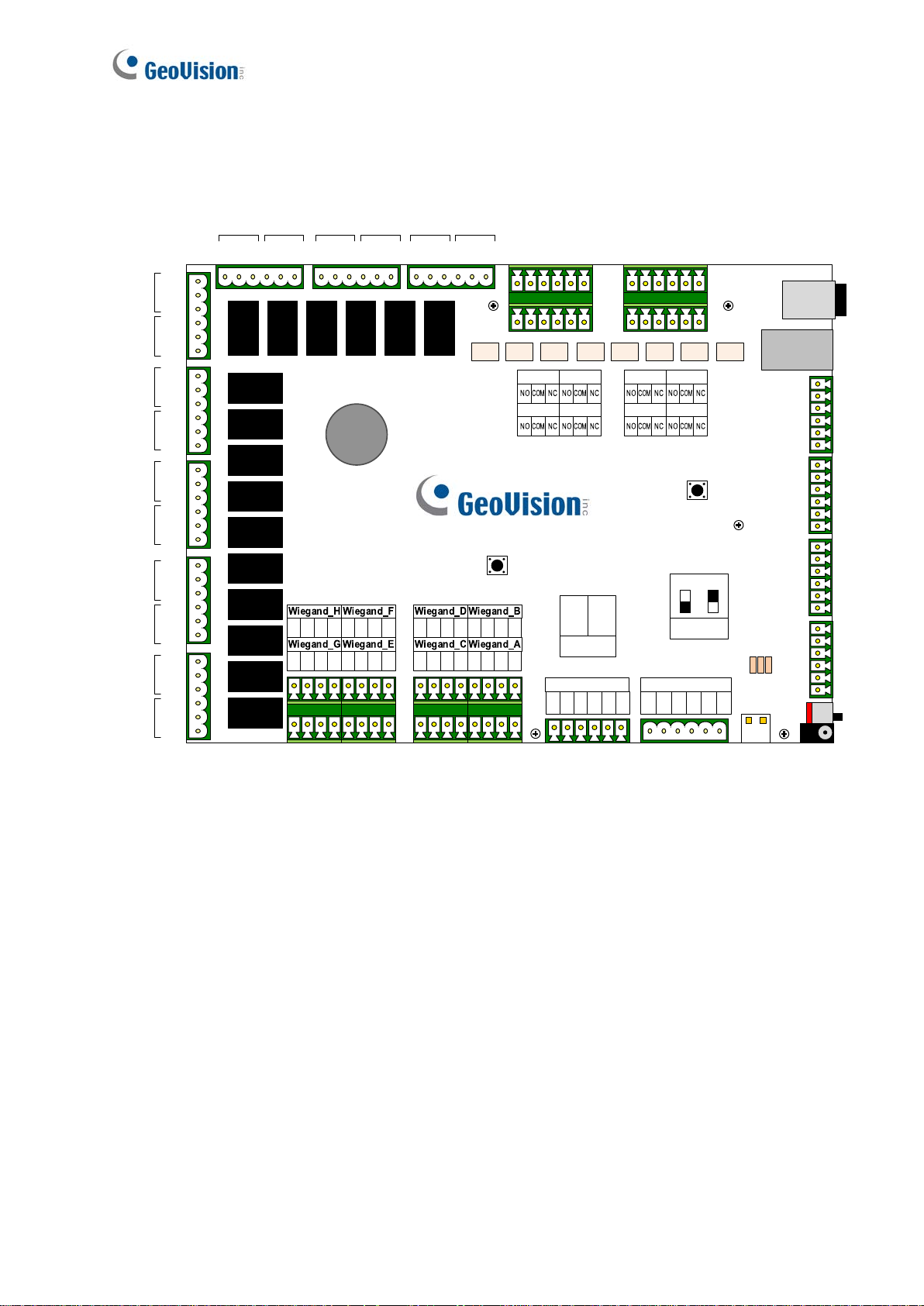
1.3 GV-AS4111 / 8111 Board Layout
Figure 1
6
Page 10

2 Installation
12V
D0
D1
GND
12V
D0
D1
GND
12V
D0
D1
GND
12V
D0
D1
GND
12V
D0
D1
GND
12V
D0
D1
GND
12V
D0
D1
GND
12V
D0
D1
GND
CON11 CON10
Connect to Wiegand compa ti ble reader s
Note: A knockout shall be provided with a surrounding surface that can seat a conduit
bushing as intended. The knockout shall be located so that installation of a bushing at any
knockout likely to be used during installation will not result in spacings between uninsulated
live parts and the bushing of less than those indicated in spacings.
2.1 Connecting Card Readers
GV-AS4111 / 8111 supports two types of card reader interfaces:
• Wiegand: Compatible with any Wiegand card readers of 26 to 64 bits.
• RS-485: Only compatible with all GV-Readers.
2.1.1 Wiegand Readers
GV-AS4111 / 8111 provides 8 Wiegand inputs (Wiegand A to Wiegand H). Connect up to 8
Wiegand readers ranging from 26 to 64 bits to the Wiegand interfaces. Please consult the
documentation of your Wiegand reader for wiring.
Figure 2
Note: Although 8 Wiegand inputs are available, GV-AS4111 only supports control of up to
4 doors.
7
Page 11

Connect each reader to the
power terminal or Wiegand
connectors for power supply
RS485
12V
A+
A-
B+
B-
GND
Up to 8 GV-Readers
12V OUTPUT
12V
GND
12V
GND
12V
GND
B+ B- Not functional
for GV-AS4111 kit
RS485_A
RS485_B
Terminal
Resistor
J37 J35
2.1.2 RS-485 Readers
For long-distance connection and non-Wiegand card readers, you can connect RS-485
connection with any GV-Readers. Using a single RS-485 cable, up to 8 readers can be
connected together with to the RS-485 A+ / A- interface. For GV-AS8111, another 8 readers
can be connected to the RS-485 B+ / B- interface , for a total of 16 R S-485 readers.
When multiple readers are connected together, an extra power supply to each unit is
required. Use 12V power output and GND on the power terminal or the Wiegand connectors
to power on each unit.
Figure 3
8
Page 12

Note:
1. Each set of 12V power output and GND can provide power for up to 2 readers. The 3
sets on the power terminal can support up to 6 readers. If you wish to connect more
readers and the Wiegand interfaces are already occupied, you can connect the
readers to external power source.
2. By default, a jumper cap is installed on the RS485_A Terminal Resister (J37) to
ensure stability when the RS-485 connection between GV-AS4111 / 8111 and the
reader is 600 meters.
3. Although up to 8 RS-485 readers can be connected, GV-AS4111 only supports control
of up to 4 doors.
9
Page 13

Ethernet
GND
IN16
IN15
GND
IN14
IN13
GND
IN12
IN11
GND
IN10
IN09
GND
IN08
IN07
GND
IN06
IN05
GND
IN04
IN03
GND
IN02
IN01
SW1
Input
Device
GND
IN
2.2 Connecting Input Devices
Up to 16 input devices can be connected to GV-AS4111 / 8111. Connect the input wires to
IN1~16 and connect GND wires to GND. Multiple GND wires can be connected to the same
GND pin.
All inputs are dry contact that can be configured as normally open (NO) or normally closed
(NC) o n the Web interface. You can change the input status through the Controller’s Web
interface.
Figure 4
10
Page 14

2.3 Connecting Output Devices
External
Power
Supply
UL 294 / UL 603 power
OUT2
OUT1
NO
COM
NC
NO
COM
NC
12V OUTPUT
12V
GND
12V
GND
12V
GND
OUT2
OUT1
NO
COM
NC
NO
COM
NC
Output
Device
Output
Device
Up to 24 output devices can be connected to GV-AS4111 / 8111. Check if your output
device meets the following absolute maximum ratings before connecting it to output terminal
block.
Outputs Outputs 1-16 Outputs 17-24
Breakdown Voltage
Continuous Load Current
30V DC 30V DC
3A 1A
Note: Absolute Maximum Ratings are those values beyond which damage to GVAS4111 / 8111 circuit board may occur. Continuous operation at the absolute rating
level may aff ect GV-AS4111 / 8111’s stability.
To connect an output device:
Connect the (+) point on the output device to COM on GV-AS4111 / 8111, connect the two (-)
points of the output device and the power supply together, and connect the (+) point on the
power supply to the NO or NC of GV-AS4111 / 8111 based on the state of the output device.
There are two ways to supply power to the output device:
Use t he power outputs on the GV-AS Controller: The total power consumption of the
output devices and readers connected to GV-AS Controller must be under 3.5A for GVAS4111 or 5A for GV-AS8111. The output device must be a 12V device.
Connect an external power supply: Connect an external power supply if the total
power consumption exceeds 3.5A / 5A or if the output device requires higher current.
Note: If you want to use the power outputs on the GV-AS Controller, note that the maximum
current of the voltage output is 12V, 0.5A.
11
Figure 5
Page 15

12V
Battery
Black
Red
(BAT)
- +
12V OUTPUT
12V
GND
12V
GND
12V
GND
CON9
SW1
Power LED
GND
IN04
IN03
GND
IN02
IN01
(BAT)
- +
SW1
2.4 Connecting Backup Battery
You can connect any 12V battery to GV-AS4111 / 8111 to provide backup power when the
main power supply fails. When the main power supply is removed and the battery voltage
level is above 10.2V, the Discharging LED will light and the battery will support normal
operation of the GV-AS4111 / 8111.
Figure 6
2.5 Connecting the Power
You can connect GV-AS4111 / 8111 to power directly using the supplied 12V DC adaptor.
After power is connected, the power LED on GV-AS4111 / 8111 should glow.
Note: Power should only be applied to the unit when all connections are completed and
tested.
Figure 7
12
Page 16

2.6 Connecting the PC
Network
PC
GV-AS4111 / 8111
Micro SD
Ethernet
GND
IN16
IN15
GND
IN14
IN13
Connecting GV-AS4111 / 8111 to a computer allows you to access its Web interface and
connect it to GV-ASManager if the computer is installed with GV-ASManager. The computer
running GV-ASManager software can be used to monitor the access information and alarm
messages from GV-AS4111 / 8111. If connection with GV-ASManager is interrupted, GVAS4111 / 8111 kit stores this information on the supplied micro SD card. The data stored will
be sent to GV-ASManager when connection resumes.
Minimum System Requirements
32-bit Windows XP / Vista / 7/ 8 / Server 2008
OS
64-bit Windows XP / Vista / 7 / 8 / Server 2008 / Server 2012
CPU Core 2 Duo E8400, 3.0 GHz
Memory 2 x 1 GB Dual Channels
Hard Disk 500 GB
VGA
AGP or PCI-Express, 1280 x 1024, 32-bit color and
support DirectX 10
DirectX End-User Runtimes (November 2008)
.NET Framework 3.5
Software
SQL Server 2005 Express (optional)
Brower Internet Explorer 7.0 or later
13
Figure 8
Page 17

Note:
1. GV-AS4111 / 8111 is only compatible with GV-ASManager V4.2.3 or later.
2. Data processing equipment and office appliance and business equipment
used as computer equipment shall comply with the Standard for
Information Technology Equipment - Safety - Part 1: General Requirements,
UL 60950-1.
3. The product shall be provided supply line transient protection complying with
the Standard for Transient Voltage Surge Suppressors, UL 1449, with a
maximum marked rating of 330 V.
4. The product shall be provided signal line transient protection complying with
the requirements for the Standard for Protectors for Data Communication and
Fire Alarm Circuits, UL 497B, with the maximum marked rating of 50 V.
5. The product shall be provided that communication circuits and network
components connected to the telecommunications network shall be protected
by secondary protectors for communication circuits. These protectors shall
comply with the Standard for Secondary Protectors For Communication
Circuits, UL 497A. T hese protectors shall be used only in the protected side of
the telecommunications network.
6. The equipment shall be installed in a temperature controlled environment. A
temperature controlled environment is defined as one that can be maintained
between 13 - 35°C (55 - 95°F) by the HVAC system. Twenty-four hours of
standby power shall be provided for the HVAC system. The standby power
system for the HVAC system may be supplied by an engine driven generator
alone. A standby battery is not required to be used.
14
Page 18

3 Other Settings
GND
IN04
IN03
GND
IN02
IN01
(BAT)
- +
SW1
Web Setting
Switch
ON OFF
OFF
ON
Ethernet
OUT21
NO
COM NC
OUT22
NO COM NC
OUT24
NO COM NC
OUT23
NO COM
NC
J14
Reset
Button
GND
IN16
IN15
GND
IN14
IN13
GND
IN12
IN11
GND
IN10
IN09
3.1 Web Setting Switch
When the Web Setting switch is set to the ON position, you can modify Advanced Settings
and Extended Reader settings of GV-AS4111 / 8111 through its Web interfaces. When the
switch is set to the OFF position, Advanced Settings and Extended Reader settings are not
accessible.
Figure 9
3.2 Resetting the GV-AS4111 / 8111
To res et GV-AS4111 / 8111, press the Reset button on the right side of GV-AS4111 / 8111
circuit board for three seconds.
15
Figure 10
Page 19

12V
D0
D1
GND
12V
D0
D1
GND
12V
D0
D1
GND
12V
D0
D1
GND
12V
D0
D1
GND
12V
D0
D1
GND
12V
D0
D1
GND
12V
D0
D1
GND
CON11 CON12
Load Default Button
3.3 Restoring Factory Defaults
To restore GV-AS4111 / 8111 to factory default settings, press the Default button for 10
seconds.
Figure 11
16
Page 20

4 GV-AS4111 / 8111 Kit
GV-AS4111 / 8111 Kit is a cabinet containing a GV-AS4111 or GV-AS 8111, a power
adapter board, a power supply and a casing for backup battery. The power supply provides
power to GV-AS4111 / 8111 and up to 8 output devices (12V, 0.5A per device).
4.1 Packing List
• GV-AS4111 Kit / GV-AS 8111 Kit
• Iron box key
• Iron box screw x 6
• Self-adhesive cable tie mounts x 6
• Battery wiring
• Micro SD Card 2 GB
• Software CD
• Warranty Car d
17
Page 21

GV-AS4111
GV-AS8111
Power Adapter
Board
Power Supply
Casing for Backup
Battery
4.2 GV-AS4111 / 8111 Kit Overview
Figure 12
18
Page 22

4.3 GV-AS4111 / 8111 Kit St andard A pplication
Black
Red
Connect each reader to the power terminal
or Wiegand connectors for power supply
Up t o 8
GV-Readers
RS485_A
RS485_B
J37 J35
Network
PC
Input
Device
GND
IN
GV-AS4111 / 8111 Kit
Micro SD
Ethernet
OUT2
OUT1
OUT11 OUT12 OUT13 OUT14 OUT15 OUT16
OUT17
OUT18
OUT20
OUT19
OUT21
OUT22
OUT24
OUT23
J13 J14
Reset
GND
IN16
IN15
GND
IN14
IN13
GND
IN12
IN11
GND
IN10
IN09
GND
IN08
IN07
GND
IN06
IN05
GND
IN04
IN03
GND
IN02
IN01
12V
D0
D1
GND
12V
D0
D1
GND
12V
D0
D1
GND
12V
D0
D1
GND
12V
D0
D1
GND
12V
D0
D1
GND
12V
D0
D1
GND
12V
D0
D1
GND
Dis-Charging
Charging
Power
CON11 CON10
Load Default
(BAT)
- +
12V OUTPUT
RS485
12V
A+A-B+
B-
GND
12V
GND
12V
GND
12V
GND
CON9J2
RS
485
_A
RS
485
_B
Terminal
Resistor
J37 J35
SW1
ON OFF
SW1
Ethernet
Enable
OUT4
OUT3
OUT6
OUT5
OUT8
OUT7
OUT10
OUT9
NO
COM
NC
NO
COM
NC
NO
COM
NC
NO
COM
NC
NO
COM
NC
NO
COM
NC
NO
COM
NC
NO
COM
NC
NO
COM
NC
NO
COM
NC
NO
COM
NC
NO
COM
NC
NO
COM
NC
NO
COM
NC
NO
COM
NC
NO
COM
NC
RTC Battery
Connec t to Wiegand
compatible readers
Output
Device
NC/NO
COM
External
Power
Supply
Internal
Power
Supply
> 100ft
< 100ft
External
Adapter
12V
Battery
+
+
-
-
ED ED+
COM
NC / NO
ED ED+
COM
NC / NO
NC / NO
COM
ED+
ED -
NC / NO
COM
ED+
ED -
NC / NO
COM
ED+
ED -
NC / NO
COM
ED +
ED -
ED -
ED+
COM
NC / NO
NO
COM
NC
Output
Device
GV-AS4111 / 8111
Power Adapter Bo ard
ED -
ED+
COM
NC / NO
(BAT)
- +
Internal
Power
Supply
Output
Power Source Limitation
Output 1 ~ 24
Class 2
Con 10 ~ Con 11
Class 2
J2
Class 2
Con 9
Class 2
J8 ~ J11 (Power board)
Class 2
J16 ~ J19 (Power board)
Class 2
19
Figure 13
Page 23

NC / NO
COM
ED+
ED -
NC / NO
COM
ED+
ED -
NC / NO
COM
ED+
ED -
NC / NO
COM
ED +
ED -
OUT2
OUT1
NO
COM
NC
NO
COM
NC
GV-AS4111 / 8111
Power Adapter Board
4.4 Connecting the GV-AS4111 / 8111 Kit
Up to 8 output devices can be powered by the power adapter board. Connect each output
device to one terminal block on the board.
1. Connect the COM pin on GV-AS4111 / 8111’s output terminal block to the
corresponding pin on the power adapter board. Connect the NC / NO pins according to
the state of the output device.
Figure 14
20
Page 24

2. Connect the ED + / - pins to the (+) and (-) points on the output device (ex: electric lock).
+
+
-
-
ED ED+
COM
NC / NO
ED ED+
COM
NC / NO
NC / NO
COM
ED+
ED -
NC / NO
COM
ED+
ED -
NC / NO
COM
ED+
ED -
NC / NO
COM
ED +
ED -
ED -
ED+
COM
NC / NO
NO
COM
NC
Output
Device
GV-AS4111 / 8111
Power Adapter Board
ED -
ED+
COM
NC / NO
(BAT)
- +
Internal
Power
Supply
Figure 15
3. When all connections are completed, connect the power supply to a 110-120V power
source.
Note:
1. The power supply of GV-AS4111 / 8111 Kit comes in US standard, UL standard, and EU
standard. Make sure the device is connected with a voltage within its voltage range.
2. You can place a backup battery in the supplied battery casing, and connect the backup
battery to the GV-AS4111 / 8111 board. Refer to 2.4 Connecting Backup Battery for
details.
21
Page 25

4.5 GV-AS4111 / 8111 Kit Specifications
Power Adapter Board
Output
Number of connectors
Wire Size (AWG)
Power Supply
Output
Input
DC Voltage Range
Rated Current
Rated Power
Input
Output
DC Voltage Range
Rated Current
Rated Power
US Standard (UL)
EU Standard
12V
0.5A
6 W
2
8
12 ~ 22
11V ~ 13V (Nominal 12V)
13A
150 W
110 ~ 120V, 50 Hz / 60 Hz, 1.7 A
200 ~ 240V, 50 Hz / 60 Hz
GV-AS4111 / 8111 Kit
Dimensions (L x W x H)
Weight
420 x 300 x 110 mm / 16.5 x 11.8 x 4.33 in
4.4 kg / 9.68 lb
22
Page 26

5 The Web Interface
You can install GV-AS4111 / 8111 on a network and configure GV-AS4111 / 8111 through
its Web interface.
23
Page 27

6 GV-AS4111 / 8111 Specifications
Software
Control Mode
One-Way Control 4 doors 8 doors
Two-Way Control
Hardware
CPU 32-bit ARM7TDMI
Number of User Cards 40, 000 cards
Event Buffer 1,000,000 events and log data
Power 100 ~ 120V AC, 50 ~ 60 Hz, 1.7A
RS-485 Interface
4 doors by Wigand,
RS-485 and Network
1 RS-485 interface 2 RS-485 interfaces
Up to 8 GV-Readers Up to 16 GV-Readers
Distance 600 m (1968.50 ft), 24 AWG, 13V DC min., 85 °C
min.
GV-AS4111 GV-AS8111
4 doors by Wiegand only
8 doors by RS-485 or
Network
8 doors with max 4 doors by
Wiegand and other doors by
RS-485 / network
Wiegand Inte r face
TCP/IP Interface 1 TCP/IP interface for GeoVision network readers
Communication Protocol TCP/IP
Battery Built-in battery, replaceable button cell (CR2032)
Input 16 inputs, dry contact, NO/NC
Output
Operating Temperature 0 ~ 65°C / 32 ~ 149°F
Operating Humidity 10% ~ 90% RH (non-condensing)
Dimensions (W X H X D) 210 x 187 x 40 mm / 8.27 x 7.36 x 1.57 in
8 Wiegand interfaces, 26 ~ 64 bit format, distance 100 m
(328.1ft), 24 AWG, 13V DC min., 85 °C min.
1~16 relay output / 30V DC, 3A
17~24 relay output / 30V DC, 1A
CON 10~CON 11, 11~13V DC (Nominal 12V DC), 0.5A
J2, 11~13V DC (Nominal 12V DC), 0.5A
CON 9, 11~13V DC (Nominal 12V DC), 0.5A
J8~J11 & J16~J19, 11~13V DC (Nominal 12V DC), 0.5A
24
Page 28

Weight 900 g / 2 lb
Certification UL, CE, FCC, RoHS
Note: The system is evaluated for the following performance levels:
Type of Approval
Feature Level
Destructive Attack 1
Line Security 1
Endurance 1
All specifications are subject to change without notice.
Standby Power 1
25
 Loading...