

Page 1
R410A
1. DUCT
AR A36LATN
AR A45LATN
INDOOR UNIT
TYPE :
D2D_AR024E/03
2007.09.13
Page 2
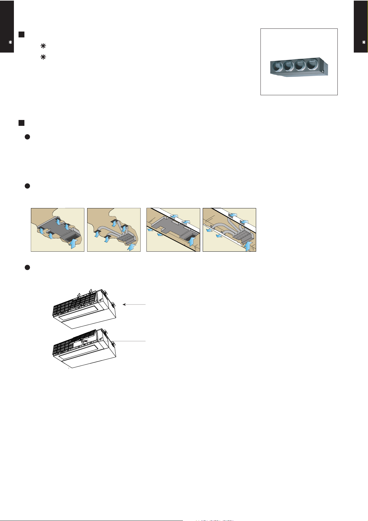
1. FEATURE
MODEL :
DUCT TYPE
AR A36LATN
AR A36-45L
DUCT TYPE
AR A36-45L
AR A45LATN
FEATURES
Energy saving
High energy saving was realized by making the indoor unit and outdoor
unit fan motor and compressor all DC and optimal design of the refrigerant cycle. Rank A was achieved in European energy rank.
Installation styles
Embedded in Ceiling
Hanging from Ceiling
Slim & compact design
In the case of bottom suction type, as seen from lower rear part.
Control Box united with main unit
One-touch operating and easy-to-install
long-life filter (optional)
In addition to the slim height of 270 mm which is our sales point, further compactification is attained by reducing 65 mm from the width with the flanking
control box embedded inside the chassis.
- (01 - 01) -
Page 3
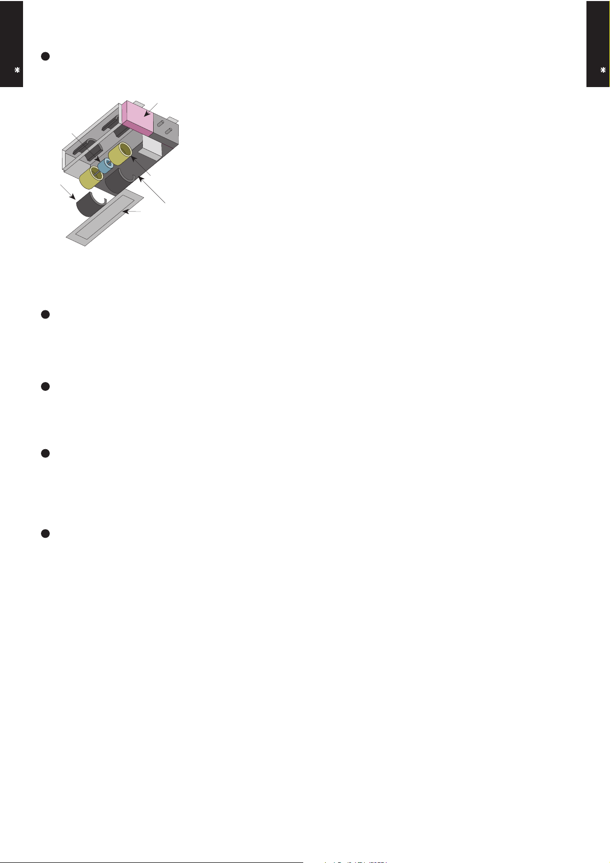
Easy maintenance
DUCT TYPE
AR A36-45L
In the case of rear suction type, as seen from lower rear part.
1
4
1.Control box
2.Fan casing
3.Fan
DUCT TYPE
AR A36-45L
4.Motor
2
3
Bottom panel: 2 units
The motor and fan maintenance and dismounting can be made easily by removing
the rear panel and lower part of the casing with the main chassis installed.
Quiet operation
Quiet operation at *29dB(A) possible by quiet mode.
* See our measurement conditions page (01-19).
Static pressure mode setting
Air flow, noise, etc. can be used under the optimum conditions by selecting
the static pressure mode matched to the installation conditions.
Room temperature adjustment correction
Suitable room temperature control is performed by changing the room temperature correction value by simple remote control operation to match the
conditions under which the air conditioner is installed.
Auto restart
The units restart automatically when the current was returned even when
there was a power interruption during operation.
- (01 - 02) -
Page 4
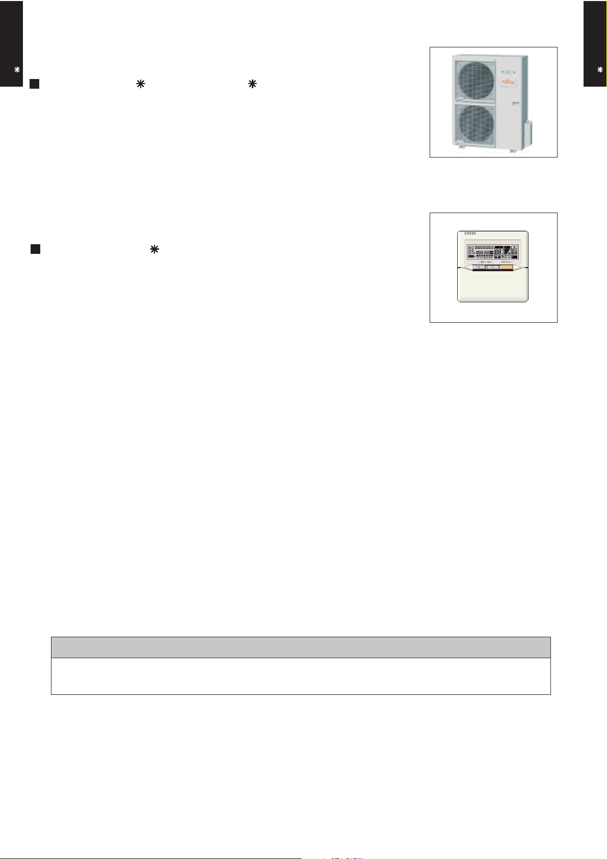
2. COMBINATION
2-1. OUTDOOR UNIT
DUCT TYPE
AR A36-45L
MODEL : AO A36LATL, AO A45LATL
2-2. REMOTE CONTROLLER
2-2-1. WIRED REMOTE CONTROLLER
MODEL : UTB- UD
DUCT TYPE
AR A36-45L
CAUTION
Remote controller is not supplied with the indoor unit.
Separate purchase is necessary.
- (01 - 03) -
Page 5
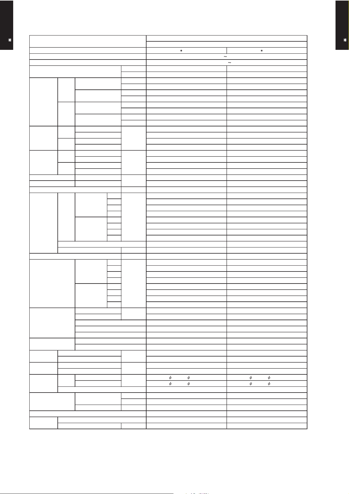
3. SPECIFICATIONS
AR A36LATN AR A45LATN
Pipe type Copper Copper
9.52 ( 3 / 8 in.) 9.52 ( 3 / 8 in.)
15.88 ( 5 / 8 in.) 15.88 ( 5 / 8 in.)
DUCTED MODEL
INVERTER HEATPUMP
230V 50Hz
198-264V 50Hz
dB(A)
Remote controller type
Drain pipe
Material
Size
Operation range
Cooling
kg(lb.)
Connection pipe
SizemmWeight
m3/h
Fan
Dimensions
( H × W × D )
mm
Airflow
rate
Enclosure
Heat exchanger type
Sound pressure level
Heating
Cooling
Heating
Heating
Cooling
Moisture removal
Cooling
Heating
Rated
*Max.
Rated
*Max.
kW/kW
Input power
Cooling
kW
Heating
Rated
*Max.
Current
Cooling
A
Power source
Available voltage range
Capacity
Cooling
Heating
European energy label
Type
Model name
mm
Rated
Min.-Max.
Rated
Min.-Max.
Rated
*Max.
DUCT TYPE
AR A36-45L
EER 3.21 3.21
COP 3.71 3.71
Type × Q'ty Sirocco × 2 Sirocco × 2
Motor output W 197 197
Recommended static pressure Pa 30 to 150 30 to 150
Dimensions (H × W × D) 294 × 1000 × 53.2 294 × 1000 × 53.2
Fin pitch 1.40 1.40
Rows x Stages 4 × 14 4 × 14
Cooling A A
Heating A A
kW 10.0 12.5
BTU/h 34100 42700
kW 3.8 - 11.2 4.0 - 14.0
BTU/h 13000 - 38200 13700 - 47800
kW 11.2 14.0
BTU/h 38200 47800
kW 4.0 - 14.0 4.2 - 16.2
BTU/h 13700 - 47800 14300 - 55300
3.11 3.89
4.33 4.56
3.02 3.77
4.33 4.56
13.6 17.0
19.0 20.0
13.2 16.5
19.0 20.0
l/h (pints/h) 3.0 (5.3) 3.5 (6.2)
High 2020 2250
Med 1710 1710
Low 1340 1340
Quiet 1020 1020
High 2020 2250
Med 1710 1710
Low 1340 1340
Quiet 1020 1020
High 42 44
Med 37 38
Low 32 33
Quiet 29 29
High 42 44
Med 37 38
Low 32 33
Quiet 29 29
DUCT TYPE
AR A36-45L
Note :
Specifications are based on the following conditions.
Cooling : Indoor temperature of 27 °CDB / 19 °CWB.and outdoor temperature of 35 °CDB/24 °CWB.
Heating : Indoor temperature of 20 °CDB / 15 °CWB.and outdoor temperature of 7 °CDB/6 °CWB.
Standard static pressure : 30Pa
Pipe length : 7.5 m, Height difference : 0 m.(Outdoor unit - Indoor unit)
Sound pressure level : Install a 2m duct to the outlet port and a 1m duct to the suction poit and measure.
*The maximum current and the maximum input value are the maximum values when operated within the operation (temperature) range.
Fin type Aluminium Aluminium
Material Steel Steel
Colour - -
Net 270 × 1135 × 700 270 × 1135 × 700
Gross 300 × 1300 × 790 300 × 1300 × 790
Net 41 ( 90 ) 41 ( 90 )
Gross 48 ( 106 ) 48 ( 106 )
Liquid
Gas
Method Flare Flare
°C 18 to 32 18 to 32
%RH 80 or less 80 or less
Heating °C 30 or less 30 or less
Wired Wired
Steel Steel
mm Outer diameter : 38.0 / Inner diameter : 36.0 Outer diameter : 38.0 / Inner diameter : 36.0
- (01 - 04) -
Page 6
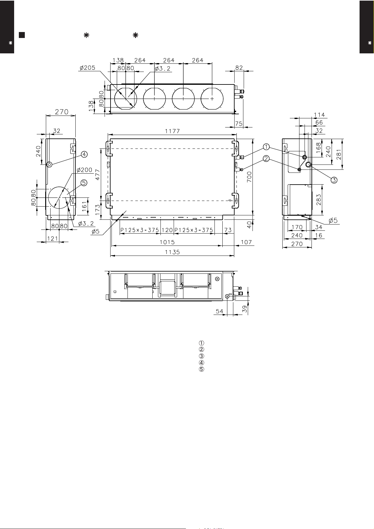
4. DIMENSIONS
MODEL : AR A36L, AR A45L
DUCT TYPE
AR A36-45L
Front view
(Unit : mm)
DUCT TYPE
AR A36-45L
Side view (L)
Top view
Rear view
Side view (R)
Refrigerant piping flare connection (Gas)
Refrigerant piping flare connection (Liquid)
Drain piping connection
Drain piping connection with cap.
Knock out hole for fresh air.
- (01 - 05) -
Page 7
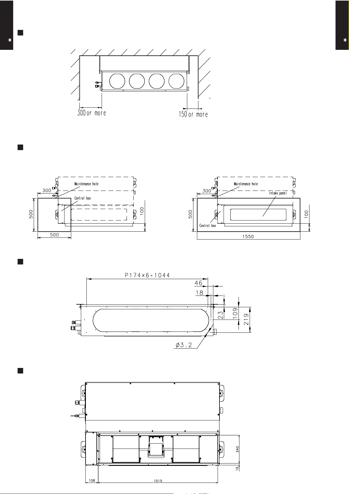
MOUNTING POSITION
DUCT TYPE
AR A36-45L
(Unit : mm)
DUCT TYPE
AR A36-45L
MAINTENANCE HOLE
It shall be possible to install and remove
the control box.
WHEN USING A SQUARE DUCT
It shall be possible to install and remove
the control box, fan units and filter.
BOTTOM AIR INTAKE HOLE
- (01 - 06) -
Page 8
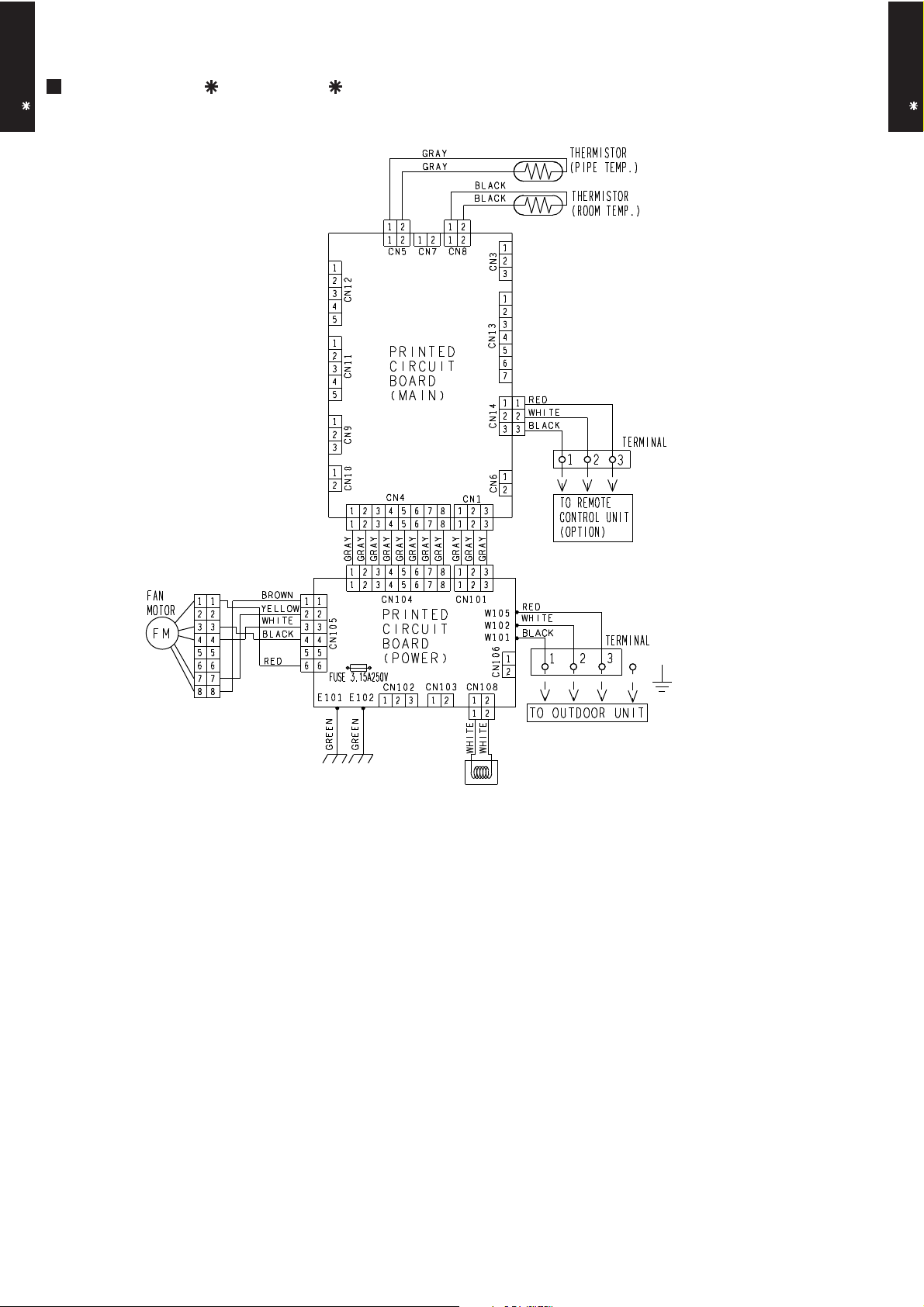
5. WIRING DIAGRAMS
MODEL : AR A36L, AR A45L
DUCT TYPE
AR A36-45L
DUCT TYPE
AR A36-45L
COIL
- (01 - 07) -
Page 9
6. CAPACITY TABLE
16
18
272932
231921
232518
21
Outdoor temperature
12
15
°CDB
-1005
20
10
15
AFR
32.2
46
25
303540
Indoor temperature
-15
-15
AFR
35.3
46
253035
40
Indoor temperature
Outdoor temperature
12
15
°CDB
-10
0520
10
15
232518
21
16
18
272932
231921
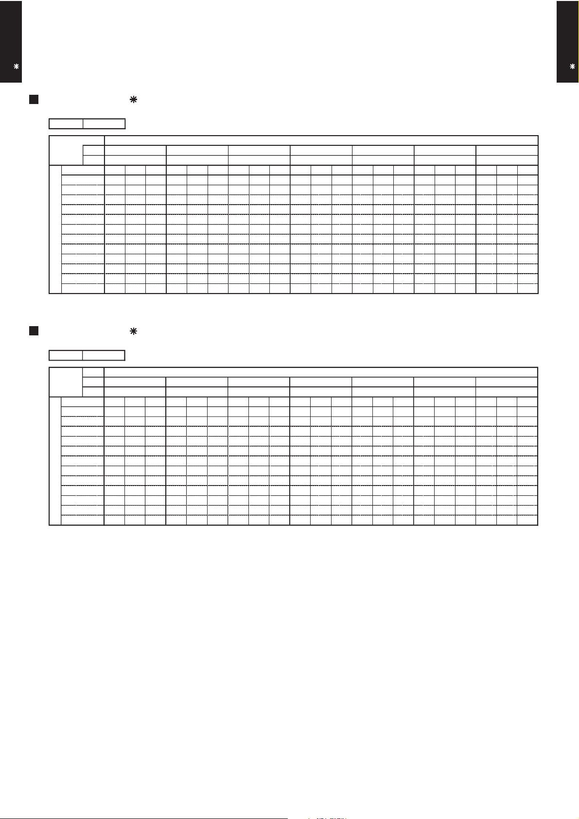
6-1. COOLING CAPACITY
DUCT TYPE
AR A36-45L
This table is created using the maximum capacity.
DUCT TYPE
AR A36-45L
MODEL :
MODEL :
AFR : Air flow rate (m3/min)
TC : Total capacity (kW)
SHC : Sensible Heat capacity (kW)
PI : Power Input (kW)
AR A36L
°CDB
°CWB
TC SHC PI TC SHC PI TC SHC PI TC SHC PI TC SHC PI TC SHC PI TC SHC PI
8.68 6.29 1.21 9.67 6.33 1.23 10.00 6.88 1.24 10.66 6.91 1.25 10.99 7.46 1.26 11.65 7.43 1.27 12.31 7.91 1.28
8.37 6.18 1.44 9.33 6.21 1.47 9.65 6.75 1.47 10.28 6.78 1.49 10.60 7.32 1.50 11.24 7.29 1.51 11.87 7.76 1.53
8.53 6.24 1.30 9.50 6.28 1.32 9.82 6.83 1.32 10.47 6.85 1.34 10.79 7.40 1.34 11.44 7.37 1.36 12.09 7.85 1.37
8.21 6.11 1.52 9.14 6.15 1.54 9.45 6.68 1.55 10.08 6.70 1.56 10.39 7.24 1.57 11.01 7.21 1.59 11.63 7.68 1.60
8.23 6.12 1.47 9.17 6.16 1.49 9.48 6.69 1.50 10.11 6.72 1.52 10.42 7.25 1.52 11.05 7.22 1.54 11.67 7.69 1.55
7.89 5.99 1.69 8.79 6.03 1.72 9.09 6.55 1.73 9.68 6.57 1.75 9.98 7.10 1.76 10.58 7.07 1.77 11.18 7.53 1.79
9.72 6.71 2.51 10.82 6.75 2.55 11.19 7.33 2.56 11.93 7.36 2.59 12.30 7.94 2.60 13.04 7.91 2.63 13.77 8.43 2.66
9.58 6.66 2.60 10.67 6.70 2.64 11.03 7.28 2.66 11.76 7.30 2.68 12.13 7.89 2.70 12.85 7.85 2.72 13.58 8.37 2.75
9.12 6.48 2.91 10.16 6.52 2.95 10.51 7.09 2.97 11.20 7.11 3.00 11.54 7.68 3.01 12.24 7.65 3.04 12.93 8.15 3.08
8.85 6.37 3.37 9.86 6.40 3.42 10.19 6.96 3.44 10.86 6.98 3.47 11.20 7.54 3.49 11.87 7.51 3.52 12.54 8.00 3.56
7.05 5.68 2.81 7.85 5.72 2.85 8.12 6.22 2.87 8.65 6.24 2.89 8.92 6.73 2.91 9.46 6.71 2.94 9.99 7.15 2.97
4.98 4.95 2.24 5.54 4.98 2.27 5.73 5.42 2.28 6.11 5.43 2.31 6.30 5.87 2.32 6.68 5.85 2.34 7.05 6.23 2.37
AR A45L
°CDB
°CWB
TC SHC PI TC SHC PI TC SHC PI TC SHC PI TC SHC PI TC SHC PI TC SHC PI
10.59 8.61 1.51 11.80 8.66 1.54 12.20 9.42 1.55 13.00 9.45 1.56 13.41 10.20 1.57 14.21 10.16 1.58 15.02 10.82 1.60
10.20 8.42 1.79 11.37 8.47 1.81 11.75 9.21 1.82 12.53 9.24 1.84 12.92 9.98 1.85 13.69 9.94 1.87 14.47 10.58 1.89
10.42 8.52 1.59 11.60 8.57 1.62 12.00 9.32 1.63 12.79 9.35 1.64 13.19 10.10 1.65 13.98 10.06 1.67 14.77 10.71 1.68
10.01 8.33 1.86 11.15 8.37 1.89 11.53 9.10 1.90 12.29 9.13 1.92 12.68 9.86 1.93 13.44 9.83 1.95 14.20 10.47 1.97
10.06 8.35 1.80 11.21 8.40 1.83 11.59 9.13 1.84 12.35 9.16 1.86 12.73 9.89 1.87 13.50 9.85 1.89 14.26 10.49 1.90
9.63 8.14 2.07 10.72 8.19 2.10 11.09 8.90 2.12 11.82 8.93 2.14 12.18 9.64 2.15 12.92 9.60 2.17 13.65 10.23 2.19
11.94 9.29 3.05 13.31 9.34 3.10 13.76 10.16 3.12 14.67 10.19 3.15 15.12 11.00 3.17 16.03 10.96 3.20 16.93 11.67 3.23
11.79 9.22 3.16 13.14 9.28 3.21 13.58 10.09 3.22 14.48 10.12 3.26 14.93 10.93 3.27 15.82 10.88 3.31 16.72 11.59 3.34
11.21 8.93 3.52 12.49 8.98 3.58 12.91 9.76 3.60 13.76 9.80 3.63 14.19 10.58 3.65 15.04 10.54 3.69 15.89 11.22 3.72
11.06 8.84 4.21 12.32 8.89 4.27 12.74 9.67 4.29 13.58 9.70 4.34 14.00 10.48 4.36 14.84 10.44 4.40 15.68 11.12 4.45
8.53 7.62 3.36 9.50 7.66 3.41 9.83 8.33 3.43 10.47 8.36 3.46 10.80 9.02 3.48 11.45 8.99 3.51 12.09 9.57 3.55
6.03 6.44 2.72 6.71 6.48 2.76 6.94 7.04 2.77 7.40 7.06 2.80 7.63 7.63 2.82 8.09 7.60 2.84 8.54 8.09 2.84
- (01 - 08) -
Page 10
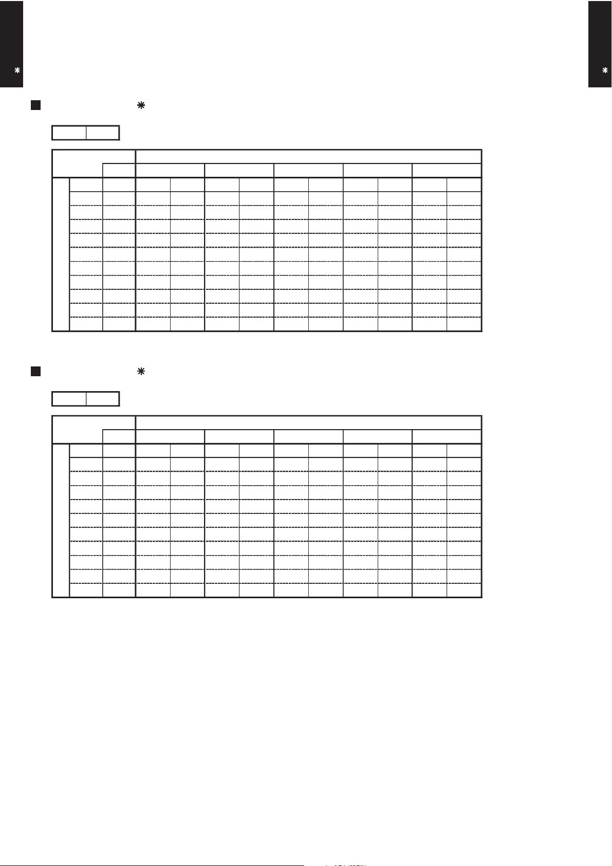
6-2. HEATING CAPACITY
24
-16
-11
-7
8
5
6
AFR
°CDB
35.3
Outdoor temperature
0
-2
151820
7
31015
10
°CDB
°CWB
-15
24
-10
-5
161820
22
Indoor temperature
24
-16
-11
-7
8
5631015
AFR
°CDB
32.2
Outdoor temperature
0
-2
151820
7
10
°CDB
°CWB
-15
24
-10
-5
161820
22
Indoor temperature
DUCT TYPE
AR A36-45L
This table is created using the maximum capacity.
DUCT TYPE
AR A36-45L
MODEL :
MODEL :
AR A36L
TC PI TC PI TC PI TC PI TC PI
10.17 3.61 9.93 3.68 9.68 3.76 9.44 3.83 9.20 3.91
10.91 3.63 10.65 3.71 10.39 3.78 10.13 3.86 9.87 3.93
11.69 3.62 11.41 3.70 11.13 3.78 10.86 3.85 10.58 3.93
12.75 3.62 12.44 3.69 12.14 3.77 11.84 3.84 11.53 3.92
13.68 3.59 13.36 3.67 13.03 3.74 12.70 3.82 12.38 3.89
14.70 3.62 14.35 3.69 14.00 3.77 13.65 3.85 13.30 3.92
15.44 3.59 15.07 3.67 14.70 3.74 14.34 3.82 13.97 3.89
14.72 3.17 14.37 3.24 14.02 3.30 13.67 3.37 13.32 3.44
14.15 2.78 13.81 2.83 13.48 2.89 13.14 2.95 12.80 2.99
14.92 2.75 14.57 2.81 14.21 2.86 13.86 2.92 13.50 2.97
AR A45L
AFR : Air flow rate (m3/min)
TC : Total capacity (kW)
PI : Power Input (kW)
TC PI TC PI TC PI TC PI TC PI
11.58 4.19 11.31 4.28 11.03 4.37 10.75 4.46 10.48 4.54
12.51 4.19 12.22 4.28 11.92 4.36 11.62 4.45 11.32 4.54
13.43 4.20 13.11 4.29 12.79 4.37 12.47 4.46 12.15 4.55
14.50 4.20 14.15 4.29 13.81 4.37 13.46 4.46 13.12 4.55
15.93 4.21 15.55 4.30 15.17 4.39 14.79 4.47 14.41 4.56
17.01 4.19 16.60 4.28 16.20 4.37 15.79 4.46 15.39 4.54
17.74 4.19 17.32 4.28 16.90 4.37 16.47 4.45 16.05 4.54
16.63 3.51 16.23 3.58 15.84 3.66 15.44 3.73 15.04 3.80
15.75 3.05 15.37 3.11 15.00 3.17 14.62 3.24 14.25 3.29
16.76 3.05 16.36 3.11 15.96 3.17 15.56 3.24 15.16 3.29
- (01 - 09) -
Page 11
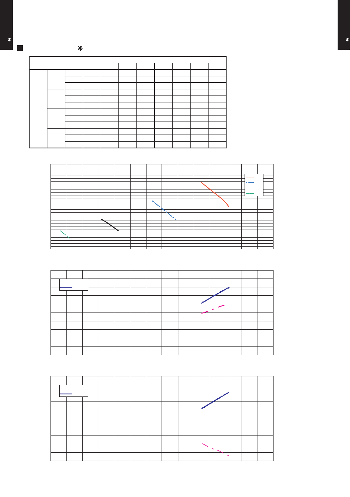
7. FAN PERFORMANCE AND CAPACITY
Hi
Med
Low
Quiet
m3/h
- - - - - 2020 1990 1850
m3/h
- - - - 1685 1585 1540 -
m3/h
- - 1325 1250 1220 - - -
m3/h
1020 995 960 - - - - -
Static pressure (Pa)
Hi
Med
Quiet
Low
7-1. NORMAL MODE
DUCT TYPE
AR A36-45L
MODEL : AR A36L
7 10 13 19 21 30 34 47
l/s - - - - - 561 553 514
CFM - - - - - 1189 1171 1089
l/s - - - - 468 440 428 -
CFM - - - - 992 933 906 -
Fan speed
l/s - - 368 347 339 - - -
CFM - - 780 736 718 - - -
l/s 283 276 267 - - - - -
CFM 600 586 565 - - - - -
Q-h Characteris tic curve
60
50
DUCT TYPE
AR A36-45L
40
30
20
Static pressure(Pa)
10
0
900 1,100 1,300 1,500 1,700 1,900 2,100 2,300
Air flow (m3/h)
102
100
98
96
94
Cooling capacity(%)Heating capacity(%)
92
900 1,10 0 1,300 1 ,500 1,700 1,900 2,100 2 ,300
Air temp
Capacity
COOLING
Air flow (m3/h)
HEATING
102
100
98
96
94
92
900 1,100 1,300 1,500 1 ,700 1,900 2,100 2,300
Air temp
Capacity
Air flow (m3/h)
- (01 - 10) -
15.0
14.5
14.0
13.5
13.0
12.5
12.0
11.5
11.0
10.5
10.0
50.0
49.0
48.0
47.0
46.0
45.0
44.0
43.0
42.0
41.0
40.0
°C)
Air temperature(
°C)
Air temperature(
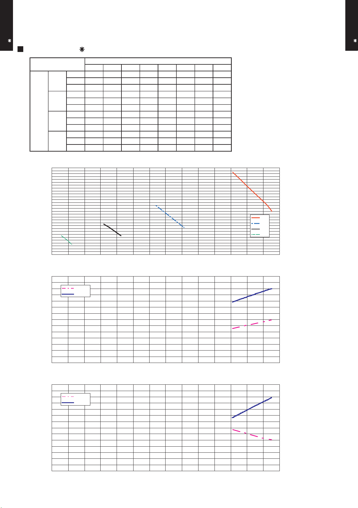
Page 12
DUCT TYPE
Hi
Med
Low
Quiet
m3/h
- - - - - 2250 2223 2010
m3/h
- - - 1710 1685 1585 1540 -
m3/h
- - 1325 1250 1220 - - -
m3/h
1020 995 960 - - - - -
Static pressure (Pa)
Hi
Med
Quiet
Low
AR A36-45L
MODEL : AR A45L
DUCT TYPE
AR A36-45L
7 10 13 19 21 30 34 57
l/s - - - - - 625 618 558
CFM - - - - - 1324 1308 1183
l/s - - - 475 468 440 428 -
CFM - - - 1006 992 933 906 -
Fan speed
l/s - - 368 347 339 - - -
CFM - - 780 736 718 - - -
l/s 283 276 267 - - - - -
CFM 600 586 565 - - - - -
Q-h Characteris tic curve
60
50
40
30
20
Static pressure(Pa)
10
0
900 1,100 1,300 1,500 1,700 1,900 2,100 2,300
Air flow (m3/h)
102
100
98
96
94
Cooling capacity(%)Heating capacity(%)
92
900 1,10 0 1,300 1 ,500 1,700 1,900 2,100 2 ,300
Air temp
Capacity
COOLING
Air flow (m3/h)
102
100
Air temp
Capacity
98
HEATING
17.0
16.0
15.0
14.0
13.0
12.0
11.0
10.0
50.0
48.0
46.0
°C)
Air temperature(
°C)
96
94
92
90
88
900 1,100 1,300 1,500 1 ,700 1,900 2,100 2,300
Air flow (m3/h)
- (01 - 11) -
44.0
42.0
40.0
Air temperature(
38.0
36.0
Page 13

7-2. STATIC PRESSURE MODE 1
Hi
Med
Low
Quiet
m3/h
- - - - - 1950 1860 1700
m3/h
- - - - 1730 1620 1520 -
m3/h
- 1340 1265 1190 - - - -
m3/h
1080 970 - - - - - -
MedHiLow
Static pressure (Pa)
Quiet
DUCT TYPE
AR A36-45L
MODEL : AR A36L
17 26 32 38 45 55 64 80
l/s - - - - - 542 517 472
CFM - - - - - 1148 1095 1001
l/s - - - - 481 450 422 -
CFM - - - - 1018 953 895 -
Fan speed
l/s - 372 351 331 - - - -
CFM - 789 745 700 - - - -
l/s 300 269 - - - - - -
CFM 636 571 - - - - - -
Q-h Characteris tic curve
90
80
70
60
50
DUCT TYPE
AR A36-45L
40
30
Static pressure(Pa)
20
10
900 1,100 1,300 1,500 1,700 1,900 2,100 2,300
Air flow (m3/h)
102
100
98
96
94
Cooling capacity(%)Heating capacity(%)
92
900 1,10 0 1,300 1 ,500 1,700 1,900 2,100 2 ,300
Air temp
Capacity
COOLING
Air flow (m3/h)
HEATING
102
100
98
96
94
92
900 1,100 1,300 1,500 1 ,700 1,900 2,100 2,300
Air temp
Capacity
Air flow (m3/h)
- (01 - 12) -
15.0
14.5
14.0
13.5
13.0
12.5
12.0
11.5
11.0
10.5
10.0
50.0
49.0
48.0
47.0
46.0
45.0
44.0
43.0
42.0
41.0
40.0
°C)
Air temperature(
°C)
Air temperature(
Page 14

DUCT TYPE
Hi
Med
Low
Quiet
m3/h
- - - - - 2100 1970 1810
m3/h
- - - 1750 1615 1520 - -
m3/h
- 1340 1190 - - - - -
m3/h
1080 970 - - - - - -
Static pressure (Pa)
Quiet
MedHiLow
AR A36-45L
MODEL : AR A45L
DUCT TYPE
AR A36-45L
17 26 38 43 55 63 75 90
l/s - - - - - 583 547 503
CFM - - - - - 1236 1159 1065
l/s - - - 486 449 422 - -
CFM - - - 1030 951 895 - -
Fan speed
l/s - 372 331 - - - - -
CFM - 789 700 - - - - -
l/s 300 269 - - - - - -
CFM 636 571 - - - - - -
Q-h Characteris tic curve
100
90
80
70
60
50
40
30
Static pressure(Pa)
20
10
900 1,100 1,300 1,500 1,700 1,900 2,100 2,300
Air flow (m3/h)
102
COOLING
17.0
100
98
96
94
92
Air temp
Capacity
Cooling capacity(%)Heating capacity(%)
90
88
900 1,10 0 1,300 1 ,500 1,700 1,900 2,100
Air flow (m3/h)
102
100
98
96
94
92
90
Air temp
Capacity
2,300
HEATING
16.0
15.0
14.0
13.0
12.0
11.0
10.0
50.0
48.0
46.0
44.0
42.0
40.0
38.0
°C)
Air temperature(
°C)
Air temperature(
88
900 1,100 1,300 1,500 1 ,700 1,900 2,100
Air flow (m3/h)
- (01 - 13) -
2,300
36.0
Page 15

7-3. STATIC PRESSURE MODE 2
Hi
Med
Low
Quiet
m3/h
- - - - - - 1850 1600
m3/h
- - - - 1600 1400 - -
m3/h
- - 1340 1180 - - - -
m3/h
1090 960 - - - - - -
Low
Static pressure (Pa)
Hi
Med
Quiet
DUCT TYPE
AR A36-45L
MODEL : AR A36L
33 40 49 60 70 85 93 112
l/s - - - - - - 514 444
CFM - - - - - - 1089 942
l/s - - - - 444 389 - -
CFM - - - - 942 824 - -
Fan speed
l/s - - 372 328 - - - -
CFM - - 789 695 - - - -
l/s 303 267 - - - - - -
CFM 642 565 - - - - - -
Q-h Characteris tic curve
130
120
110
100
90
80
70
60
Static pressure(Pa)
50
40
30
900 1,100 1,300 1,500 1,700 1,900 2,100 2,300
102
Air temp
Capacity
Air temp
Capacity
100
98
96
94
Cooling capacity(%)Heating capacity(%)
92
900 1,10 0 1,300 1 ,500 1,700 1,900 2,100 2 ,300
102
100
98
96
94
92
900 1,100 1,300 1,500 1 ,700 1,900 2,100 2,300
Air flow (m3/h)
Air flow (m3/h)
Air flow (m3/h)
- (01 - 14) -
COOLING
HEATING
15.0
14.5
14.0
13.5
13.0
12.5
12.0
11.5
11.0
10.5
10.0
50.0
49.0
48.0
47.0
46.0
45.0
44.0
43.0
42.0
41.0
40.0
DUCT TYPE
AR A36-45L
°C)
Air temperature(
°C)
Air temperature(
Page 16

DUCT TYPE
Hi
Med
Low
Quiet
m3/h
- - - - - - 1900 1660
m3/h
- - - - 1600 1400 - -
m3/h
- - 1340 1180 - - - -
m3/h
1090 960 - - - - - -
Low
Static pressure (Pa)
Hi
Med
Quiet
AR A36-45L
MODEL : AR A45L
DUCT TYPE
AR A36-45L
33 40 49 60 70 85 100 120
l/s - - - - - - 528 461
CFM - - - - - - 1118 977
l/s - - - - 444 389 - -
CFM - - - - 942 824 - -
Fan speed
l/s - - 372 328 - - - -
CFM - - 789 695 - - - -
l/s 303 267 - - - - - -
CFM 642 565 - - - - - -
Q-h Characteris tic curve
130
120
110
100
90
80
70
60
Static pressure(Pa)
50
40
30
900 1,100 1,300 1,500 1,700 1,900 2,100 2,300
Air flow (m3/h)
102
COOLING
17.0
100
98
96
94
92
Air temp
Capacity
Cooling capacity(%)Heating capacity(%)
90
88
900 1,10 0 1,300 1 ,500 1,700 1,900 2,100 2 ,300
102
100
Air flow (m3/h)
Air temp
Capacity
98
96
94
92
90
HEATING
16.0
15.0
14.0
13.0
12.0
11.0
10.0
50.0
48.0
46.0
44.0
42.0
40.0
38.0
°C)
Air temperature(
°C)
Air temperature(
88
900 1,100 1,300 1,500 1 ,700 1,900 2,100 2,300
Air flow (m3/h)
- (01 - 15) -
36.0
Page 17

7-4. STATIC PRESSURE MODE 3
Hi
Med
Low
Quiet
m3/h
- - - - - - 1730 1500
m3/h
- - - - 1530 1310 - -
m3/h
- - 1330 1140 - - - -
m3/h
1110 960 - - - - - -
Static pressure (Pa)
Quiet
MedHiLow
DUCT TYPE
AR A36-45L
MODEL : AR A36L
55 63 77 89 102 117 130 150
l/s - - - - - - 481 417
CFM - - - - - - 1018 883
l/s - - - - 425 364 - -
CFM - - - - 901 771 - -
Fan speed
l/s - - 369 317 - - - -
CFM - - 783 671 - - - -
l/s 308 267 - - - - - -
CFM 653 565 - - - - - -
Q-h Characteris tic curve
150
140
130
120
110
100
90
80
Static pressure(Pa)
70
60
50
900 1,100 1,300 1,500 1,700 1,900 2,100 2,300
102
Air temp
Capacity
Air temp
Capacity
100
98
96
94
Cooling capacity(%)Heating capacity(%)
92
900 1,10 0 1,300 1 ,500 1,700 1,900 2,100 2 ,300
102
100
98
96
94
92
900 1,100 1,300 1,500 1 ,700 1,900 2,100 2,300
Air flow (m3/h)
Air flow (m3/h)
Air flow (m3/h)
- (01 - 16) -
COOLING
HEATING
15.0
14.5
14.0
13.5
13.0
12.5
12.0
11.5
11.0
10.5
10.0
50.0
49.0
48.0
47.0
46.0
45.0
44.0
43.0
42.0
41.0
40.0
DUCT TYPE
AR A36-45L
°C)
Air temperature(
°C)
Air temperature(
Page 18

DUCT TYPE
Hi
Med
Low
Quiet
m3/h
- - - - - - 1730 1500
m3/h
- - - - 1530 1310 - -
m3/h
- - 1330 1140 - - - -
m3/h
1110 960 - - - - - -
MedHiLow
Static pressure (Pa)
Quiet
AR A36-45L
MODEL : AR A45L
DUCT TYPE
AR A36-45L
55 63 77 89 102 117 130 150
l/s - - - - - - 481 417
CFM - - - - - - 1018 883
l/s - - - - 425 364 - -
CFM - - - - 901 771 - -
Fan speed
l/s - - 369 317 - - - -
CFM - - 783 671 - - - -
l/s 308 267 - - - - - -
CFM 653 565 - - - - - -
Q-h Characteris tic curve
150
140
130
120
110
100
90
80
Static pressure(Pa)
70
60
50
900 1,100 1,300 1,500 1,700 1,900 2,100 2,300
Air flow (m3/h)
102
COOLING
17.0
100
98
96
94
92
Cooling capacity(%)Heating capacity(%)
90
88
900 1,10 0 1,300 1 ,500 1,700 1,900 2,100 2 ,300
Air temp
Capacity
Air flow (m3/h)
102
100
Air temp
Capacity
98
96
94
92
90
HEATING
16.0
15.0
14.0
13.0
12.0
11.0
10.0
50.0
48.0
46.0
44.0
42.0
40.0
38.0
°C)
Air temperature(
°C)
Air temperature(
88
900 1,100 1,300 1,500 1 ,700 1,900 2,100 2,300
Air flow (m3/h)
- (01 - 17) -
36.0
Page 19

8. OPERATION NOISE
HIGH
QUIET
HIGH
QUIET
HIGH
QUIET
HIGH
QUIET
8-1. NOISE LEVEL CURVE
DUCT TYPE
AR A36-45L
COOLING
MODEL : AR A36L
80
70
60
50
40
30
20
Octave band sound pressure level, dB:(0dB=0.0002µbar)
10
NC-65
NC-60
NC-55
NC-50
NC-45
NC-40
NC-35
NC-30
NC-25
NC-20
NC-15
MODEL : AR A45L
80
70
60
50
40
30
20
Octave band sound pressure level, dB:(0dB=0.0002µbar)
10
Condition
Static pressure : 30Pa
Static pressure mode : Normal
NC-65
NC-60
NC-55
NC-50
NC-45
NC-40
NC-35
NC-30
NC-25
NC-20
NC-15
DUCT TYPE
AR A36-45L
0
63 125 250 500 1,000 2,000 4,000 8,000
Octave band center frequency,Hz
HEATING
MODEL : AR A36L
80
70
60
50
40
30
20
Octave band sound pressure level, dB:(0dB=0.0002µbar)
10
NC-65
NC-60
NC-55
NC-50
NC-45
NC-40
NC-35
NC-30
NC-25
NC-20
NC-15
0
63 125 250 500 1,000 2,000 4,000 8,000
Octave band center frequency,Hz
MODEL : AR A45L
80
70
60
50
40
30
20
Octave band sound pressure level, dB:(0dB=0.0002µbar)
10
NC-65
NC-60
NC-55
NC-50
NC-45
NC-40
NC-35
NC-30
NC-25
NC-20
NC-15
0
63 125 250 500 1,000 2,000 4,000 8,000
Octave band center frequency,Hz
- (01 - 18) -
0
63 125 250 500 1,000 2,000 4,000 8,000
Octave band center frequency,Hz
Page 20

8-2. SOUND LEVEL CHECK POINT
DUCT TYPE
AR A36-45L
Measuring duct
Microphone Microphone
Measuring duct
DUCT TYPE
AR A36-45L
- (01 - 19) -
Page 21

9. ELECTRIC CHARACTERISTICS
AR A36L AR A45L
mm
2
1.5 - 2.5 1.5 - 2.5
Power supply
230
50
Wiring spec.
(Indoor unit to outdoor unit)
DUCT TYPE
AR A36-45L
Model name
Voltage V
Frequency Hz
Max. operating current (Indoor unit) A 2.0 2.1
Connection cable
Limited wiring length m 51 51
DUCT TYPE
AR A36-45L
- (01 - 20) -
Page 22

10. SAFETY DEVICES
Protection form
Model
Fan motor protection
3.15A 250V
1.90±0.24A
115±10°C OFF
90±10°C ON
DUCT TYPE
AR A36-45L
Circuit protection Current fuse (PCB)
Over current protection
Thermal protection program
AR A36L AR A45L
DUCT TYPE
AR A36-45L
- (01 - 21) -
Page 23

11. OPTIONAL PARTS
DUCT TYPE
AR A36-45L
Exterior Summary
Parts name
Model No.
DUCT TYPE
AR A36-45L
Wired remote
controller
Square flange
Round flange
UTB- UD
UTD-SF045T
UTD-RF204
Unit control is performed by
wired remote controller.
Both the Square flange and
the Round flange can be
selected.
Round flange is also used
when the fresh air duct is
installed.
200mm
507mm
2000mm
Long-life filter
Flexible duct
Remote sensor
UTD-LF25NA
UTD-RD202
UTD-RS100
Long-life filter can be
mounted to the indoor unit.
Connect to Round flange and
used at fan and fresh air ducts.
New amenity space can be
offered by installing the
Remote sensor in the remote
controller.
External
control set
- (01 - 22) -
UTD-ECS5A
Use to connect with various
peripheral devices and air
conditioner PC board.
Page 24

R410A
OUTDOOR UNIT
2.
SINGLE TYPE :
AO A36LATL
AO A45LATL
D2D_AO009E/02
2007.09.07
Page 25

1. SPECIFICATIONS
AO A36LATL AO A45LATL
1260 × 900 × 36.4
1260 × 900 × 36.4
Colour
Net
Gross
Motor output
Type
Charge
Type
Material
Motor output
Cooling
Heating
Dimensions (H × W × D)
Type
Model name
Power source
Available voltage range
1290 × 900 × 330
98 (216)
107 (236)
15.88 ( 5/8 in.)
Flare
-15 to 46
-15 to 24
1430 × 1050 × 445
9.52 ( 3/8 in.)
Copper
Aluminium
Steel sheet
Beige (10YR7.5/1.0NN)
Twin Rotary × 1
3750
R410A
POE
3350
INVERTER HEATPUMP
230V 50Hz
198-264V 50Hz
Propeller × 2
m
Connection pipe
Size
mm
Liquid
Gas
Method
Max. length
Max. height difference
Compressor
Refrigerant
Sound pressure level
Starting current
Cooling
Heating
Type × Q'ty
Refrigerant oil
Enclosure
Heat exchanger type
Fin pitch
Rows x Stages
Pipe type
Fin type
Type × Q'ty
mm
Weight
kg(lb.)
Dimensions
(H × W × D)
Net
Gross
°C
Operation range
Fan
Airflow
rate
m3/h
dB(A)
mm
Cooling
Heating
OUTDOOR UNIT
AO A36-45L
A 15.0 15.0
6600 6600
6600 6600
W 103 × 2 103 × 2
54 55
55 56
1.30 1.30
2 × 60 2 × 60
W
OUTDOOR UNIT
AO A36-45L
g
50 (chargeless : 20) 50 (chargeless : 20)
30 30
Note :
Specifications are based on the following conditions.
Cooling : Indoor temperature of 27°CDB/19°CWB. and outdoor temperature of 35°CDB/24°CWB.
Heating : Indoor temperature of 20°CDB/15°CWB. and outdoor temperature of 7°CDB/6°CWB.
Pipe length : 7.5 m, Height difference : 0 m. (Outdoor unit - Indoor unit)
- (02 - 01) -
Page 26

2. DIMENSIONS
MODEL : AO A36L, AO A45L
(Unit : mm)
Top view
OUTDOOR UNIT
AO A36-45L
1290
900
77 31
12330
OUTDOOR UNIT
AO A36-45L
21
370
Drain cap
mounting places
MOUNTING POSITION
When there are
obstacles at the
back or front side.
When there are obstacles
at the back and front sides.
9
Front view
650
Air flow
Bottom view
400
Side view
4-Ø12mm hole
When there are obstacles at
the back, side(s), and top.
151
170
196
99
When there are obstacles
at the back side with the
installation of more than
one unit.
100 mm
or more
* If the space is larger than that is stated, the condition will be the same as that there are no obstacles.
600 mm
or more
100 mm
or more
100 to 300 mm *
- (02 - 02) -
250 mm or
(
Ser
v
ice
600 to 1000 mm
250 mm
or more
300 mm
300 mm
or more
mo
s
pa
r
e
c
e)
250 mm
or more
or more
Page 27

3. REFRIGERANT CIRCUIT
MODEL : AO A36L, AO A45L
OUTDOOR UNIT
AO A36-45L
OUTDOOR UNIT
AO A36-45L
- (02 - 03) -
Page 28

4. WIRING DIAGRAMS
MODEL : AO A36L, AO A45L
OUTDOOR UNIT
AO A36-45L
OUTDOOR UNIT
AO A36-45L
- (02 - 04) -
Page 29

5. COEFFICIENT OF COMPENSATION FOR PIPE LENGTH
AND HEIGHT DIFFERENCE
This table is created using the maximum capacity.
MODEL : AO A36L
COOLING
OUTDOOR UNIT
AO A36-45L
1
Indoor unit is upper
than outdoor unit.
Height
difference H
(m)
2
Indoor unit is under
than outdoor unit
HEATING
1
Indoor unit is upper
than outdoor unit.
Height
difference H
(m)
2
Indoor unit is under
than outdoor unit
30 - - - -
20 - - -
10 - -
7.5 -
5
0 1.009 1.000 0.985 0.940 0.929 0.926 0.905
-5
-7.5 -
-10 - -
-20 - - -
-30 - - - -
30 - - - -
20 - - -
10 - -
7.5 -
5
0 0.978 1.000 1.016 0.985 0.971 0.950 0.927
-5
-7.5 -
-10 - -
-20 - - -
-30 - - - -
5 7.5 10 20 30 40 50
0.988 0.973 0.929 0.918 0.914 0.894
1.001 0.992 0.977 0.932 0.921 0.918 0.898
1.009 1.000 0.985 0.940 0.929 0.926 0.905
1.000 0.985 0.940 0.929 0.926 0.905
5 7.5 10 20 30 40 50
1.000 1.016 0.985 0.971 0.950 0.927
0.978 1.000 1.016 0.985 0.971 0.950 0.927
0.973 0.995 1.011 0.980 0.966 0.945 0.923
0.993 1.009 0.978 0.963 0.943 0.920
Pipe length (m)
0.884 0.881 0.862
0.910 0.899 0.896 0.876
0.969 0.925 0.914 0.911 0.890
0.985 0.940 0.929 0.926 0.905
0.940 0.929 0.926 0.905
0.929 0.926 0.905
Pipe length (m)
0.971 0.950 0.927
0.985 0.971 0.950 0.927
1.016 0.985 0.971 0.950 0.927
1.006 0.975 0.961 0.940 0.918
0.966 0.951 0.931 0.909
0.942 0.921 0.899
OUTDOOR UNIT
AO A36-45L
Indoor unit
H
Outdoor unit
Connection pipe
1
Indoor unit is upper than outdoor unit.
Height difference H
Outdoor unit
Connection pipe
2
Indoor unit is under than outdoor unit.
- (02 - 05) -
H
Indoor unit
Page 30

This table is created using the maximum capacity.
MODEL : AO A45L
COOLING
OUTDOOR UNIT
AO A36-45L
1
Indoor unit is upper
than outdoor unit.
Height
difference H
(m)
2
Indoor unit is under
than outdoor unit
HEATING
1
Indoor unit is upper
than outdoor unit.
Height
difference H
(m)
2
Indoor unit is under
than outdoor unit
30 - - - -
20 - - -
10 - -
7.5 -
5
0 1.009 1.000 0.995 0.949 0.938 0.935 0.914
-5
-7.5 -
-10 - -
-20 - - -
-30 - - - -
30 - - - -
20 - - -
10 - -
7.5 -
5
0 0.978 1.000 1.016 0.985 0.971 0.950 0.927
-5
-7.5 -
-10 - -
-20 - - -
-30 - - - -
5 7.5 10 20 30 40 50
0.988 0.983 0.938 0.927 0.924 0.903
1.001 0.992 0.987 0.942 0.931 0.927 0.907
1.009 1.000 0.995 0.949 0.938 0.935 0.914
1.000 0.995 0.949 0.938 0.935 0.914
5 7.5 10 20 30 40 50
1.000 1.016 0.985 0.971 0.950 0.927
0.978 1.000 1.016 0.985 0.971 0.950 0.927
0.973 0.995 1.011 0.980 0.966 0.945 0.923
0.993 1.009 0.978 0.963 0.943 0.920
Pipe length (m)
0.893 0.890 0.870
0.919 0.908 0.905 0.885
0.979 0.934 0.923 0.920 0.899
0.995 0.949 0.938 0.935 0.914
0.949 0.938 0.935 0.914
0.938 0.935 0.914
Pipe length (m)
0.971 0.950 0.927
0.985 0.971 0.950 0.927
1.016 0.985 0.971 0.950 0.927
1.006 0.975 0.961 0.940 0.918
0.966 0.951 0.931 0.909
0.942 0.921 0.899
OUTDOOR UNIT
AO A36-45L
Indoor unit
H
Outdoor unit
Connection pipe
1
Indoor unit is upper than outdoor unit.
Height difference H
Outdoor unit
Connection pipe
2
Indoor unit is under than outdoor unit.
- (02 - 06) -
H
Indoor unit
Page 31

6. ADDITIONAL CHARGE CALCULATION
Refrigerant type
R410A
3350
50g/m
MODEL : AO A36L, AO A45L
Refrigerant amount g
OUTDOOR UNIT
AO A36-45L
REFRIGERANT CHARGE
Pipe length m 20 30 40 50
Additional charge g 0 (Chargeless) +500 +1000 +1500
OUTDOOR UNIT
AO A36-45L
- (02 - 07) -
Page 32

7. AIR FLOW
Air flow
Lower fan
3884
Upper fan
850
m3/h
6600
l/s
1833
Number of
rotations
(r.p.m)
750
CFM
Number of
rotations
(r.p.m)
Upper fan
850
m3/h
6600
l/s
1833
Lower fan
750
CFM
3884
Air flow
MODEL : AO A36L, AO A45L
COOLING
OUTDOOR UNIT
AO A36-45L
HEATING
OUTDOOR UNIT
AO A36-45L
- (02 - 08) -
Page 33

8. OPERATION NOISE
8-1. NOISE LEVEL CURVE
COOLING
MODEL : AO A36L
80
70
OUTDOOR UNIT
AO A36-45L
60
50
40
30
20
Octave band sound pressure level, dB:(0dB=0.0002µbar)
10
0
63 125 250 500 1,000 2,000 4,000 8,000
Octave band center frequency,Hz
NC-65
NC-60
NC-55
NC-50
NC-45
NC-40
NC-35
NC-30
NC-25
NC-20
NC-15
MODEL : AO A45L
80
70
60
50
40
30
20
Octave band sound pressure level, dB:(0dB=0.0002µbar)
10
0
63 125 250 500 1,000 2,000 4,000 8,000
Octave band center frequency,Hz
NC-65
NC-60
NC-55
NC-50
NC-45
NC-40
NC-35
NC-30
NC-25
NC-20
NC-15
OUTDOOR UNIT
AO A36-45L
HEATING
MODEL : AO A36L
80
70
60
50
40
30
20
Octave band sound pressure level, dB:(0dB=0.0002µbar)
10
NC-65
NC-60
NC-55
NC-50
NC-45
NC-40
NC-35
NC-30
NC-25
NC-20
NC-15
MODEL : AO A45L
80
70
60
50
40
30
20
Octave band sound pressure level, dB:(0dB=0.0002µbar)
10
NC-65
NC-60
NC-55
NC-50
NC-45
NC-40
NC-35
NC-30
NC-25
NC-20
NC-15
0
63 125 250 500 1,000 2,000 4,000 8,000
Octave band center frequency,Hz
- (02 - 09) -
0
63 125 250 500 1,000 2,000 4,000 8,000
Octave band center frequency,Hz
Page 34

8-2. SOUND LEVEL CHECK POINT
OUTDOOR UNIT
AO A36-45L
OUTDOOR UNIT
AO A36-45L
- (02 - 10) -
Page 35

9. ELECTRIC CHARACTERISTICS
Model Name AO A36L AO A45L
Voltage V
230
Power Supply
Frequency Hz
50
Max. Operating Current A 19.0 20.0
OUTDOOR UNIT
AO A36-45L
Starting Current A
Main Fuse (Circuit breaker)
Current
*1) Wiring Spec.
Power Cable
mm
A
2
*2)Limited wiring length m
15.0
30
5.3 - 6.0
17
OUTDOOR UNIT
AO A36-45L
*1) Wiring Spec. :
Selected Sample
(Selected based on Japan Electrotechnical Standard and Codes Committee E0005)
*2) Limited Wiring length :
This is the wiring length in case voltage descent is less than 2%.
When the wiring length becomes long, please select the wiring of a more larger diameter.
- (02 - 11) -
Page 36

10. SAFETY DEVICES
AO A36L AO A45L
Current fuse
(MAIN PRINTED CIRCUIT BOARD)
Current fuse
(MAIN PRINTED CIRCUIT BOARD)
Thermal protection program (COMPRESSOR TEMP.)
Thermal protection program (DISCHARGE TEMP.)
Protection form
25A 250V
10A 250V
Model
5A 250V
3.15A 250V
Compressor protection
Circuit protection
OFF : 110°C
ON : 80°C
OFF : 115°C
ON : After 7 minutes
OFF : 130±20°C
ON : 100±20°C
OFF : 4.2±0.1MPa
ON : 3.2±0.15MPa
OUTDOOR UNIT
AO A36-45L
Fan motor protection Thermal protection program
High Pressure Protection High Pressure Switch
Current fuse (NEAR THE TERMINAL)
Current fuse (NEAR THE TERMINAL)
OUTDOOR UNIT
AO A36-45L
- (02 - 12) -
Page 37

REMOTE CONTROLLER
3. WIRED REMOTE CONTROLLER
UTB - UD
:
D2D_RC001E/02
2007.09.03
Page 38

REMOTE CONTROLLER UTB- UD
FEATURES
Various timer setup (ON / OFF / WEEKLY) are possible.
Equipped with weekly timer as standard function.
(2 times Start / Stop per day for a week)
When setting up a timer, operation mode and a temperature
setup can be changed.
When a failure occurs,the error code is displayed. (Maximum of 16)
Error indication.(A maximum of 16 error histories are memorizable.)
Up to 16 indoor units can be simultaneously controlled.
Economy operation are possible.
Easy installation with a slim shape with no bulge in the back.
The room temperature can be controlled by being detected the temperature
accurately with built-in thermo sensor.
Simple function setting
Setting of the air conditioner selection function is performed by remote controller.
High performance and compact size
REMOTE CONTROLLER UTB- UD
Three functions are combined in
one unit.
Wired
remote
controller
Built-in timers
Possible to set ON/OFF time to operate twice each day
of the week.
SUMOTUWETH FR SA
7
3126 9
15 18 21
Setup screen example
(Set to Wednesday: 8:00 to 20:00.)
0 3 6 9 12 15 18 21 Time
At "Weekly timer" + "Set back timer" setup
Easy-to-understand time bar display
SUMOTUWETH FR SA
7
3126 9
15 18 21
24°C
24°C 28°C 24°C
Weekly
timer
Setback
timer
Setback timerWeekly timer
Possible to set temperature for two time spans and
for each day of the week.
SUMOTUWETH FR SA
Screen
after setup
Setup screen example
(Set from Sunday to Saturday: 12:00 to 15:00, 28 °C.)
0 3 6 9 12 15 18 21 Time
24°C
0 3 6 9 12 15 18 21 Time
28°C
3126 9
15 18 21
28°C
Easy-to-understand operation Simple installation
Components are compatible with standard
switch boxes. Flat back construction allows
equipment to be installed wherever it is
needed.
Timer
area
[
Variable timer control
]
The operation/display sections are zoned according to time and operation, enabling variable programming to match application.
Operation
area
European
switch box
- (03 - 01) -
JIS box
Page 39

REMOTE CONTROLLER UTB- UD
FUNCTIONS
2
6
7
8
9
10
11
Display panel
16
19
20
18
17
15
13
12
14
1
START/STOP button
Pressed to start and stop operation.
2
Set temperature button
Selects the setting temperature.
3
Master control button
Selects the operating mode(AUTO, HEAT, FAN, COOL, DRY).
4
1
3
4
5
Fan control button
Selects the fan speed (AUTO, QUIET, LOW, MED, HIGH).
5
Economy button
Turns the economy efficient mode on and off.
6
Timer mode (CLOCK ADJUST) button
Selects the timer mode (OFF TIMER, ON TIMER, WEEKLY TIMER)
Set the current time.
7
Day (DAY OFF) button
Temporarily cancels of one day timer.
8
Set back button
Pressed to select the set back timer.
9
Set time button
Pressed to set time.
10
Delete button
The schedule of a weekly timer is deleted.
11
Set button
Sets the date, hour, minute and on-off time.
12
Vertical airflow direction and swing button
Push for two seconds to change the swing mode.
13
Horizontal airflow direction and swing button
Push for two seconds to change the swing mode.
REMOTE CONTROLLER UTB- UD
DIMENSION
120
Front View
SPECIFICATION
21
[ Unit : mm ]
120
14
Filter button
15
Operation lamp
Lights during operation and when the timer is on.
16
Timer and clock display
17
17
Operation mode display
18
Fan speed display
19
Operation lock display
20
Temperature display
21
Function display
Defrost display
Thermo sensor display
Economy display
Vertical swing display
Horizontal swing display
Filter display
SIZE (H x W x D mm) 120 x 120 x 17
WEIGHT ( g ) 160
CABLE LENGTH ( m )
POWER ( V )
10
12
- (03 - 02) -
 Loading...