

Page 1

g
Spectra RMS™ Circuit Breakers
Motor-Operated Mechanisms for Spectra RMS™
Breaker Types SE150, SF250
Description
A motor-operated mechanism is designed to open, close,
and reset a circuit breaker by remote control.
In an operating installation, the customer must supply
normally open ON and OFF push-buttons, external wiring,
a control power source, and any control circuitry.
Electrical Operation
With the breaker and operating mechanism in their OFF
positions, press the ON button to energize the motor,
closing the breaker. When the breaker handle reaches the
ON position, the control circuitry is disconnected by an
internal limit switch.
When the OFF button is pressed, the motor is energized,
opening the breaker. After the breaker handle reaches the
OFF position, a limit switch de-energizes the control
circuit.
When the circuit breaker trips automatically, there is no
external trip indication, unless a separate bell alarm
accessory is provided to actuate a warning device. It is
necessary to press OFF to reset the breaker.
GEH-5613 Installation Instructions
Type
SE150
Push to
Open
Automatic Reset
For automatic reset, an auxiliary switch, available as an
accessory, returns the breaker to the OFF/RESET position
after it has tripped. The switch is mounted inside the
breaker and wired in parallel with the OFF button. When
the breaker trips, the switch closes, moving the breaker
handle to the OFF/RESET position. After the motoroperated mechanism has reset the breaker, the limit switch
again opens the circuit. To use automatic reset, the ON
push-button must be SPDT type and wired as in Figure 5.
(The Auto/Reset scheme applies to ac devices only and is
not applicable for dc applications.
Manual Operation
Lift the cover to disengage the handle and operate the
breaker handle. To return to electrical operation, align the
breaker handle with the operating mechanism and close
the cover.
Type
SF250
Figure 1. Spectra RMS circuit breakers.
Page 2
Electrical Data
Table 1 contains the electrical specifications for the motoroperated mechanism.
Control Timing (Sec)
Catalog
No. Volts
SEMOM1 120 Vac 10.5 5.0
SFMOM1 125 Vdc 13.5 4.0
SEMOM2
SFMOM2
SEMOM8
SFMOM8
SEMOM9
SFMOM9
240 Vac 6.5 3.0
24 Vdc 31 15.5
48 Vdc 20 7.0
In-Rush
Amps
Running
Amps Closing
Opening
Reset
.15 .13
Table 1. Electrical specifications.
Recommended
Fuse
1 Amp
Time Delay
2 Amp
Time Delay
Move Shutter
if Necessary
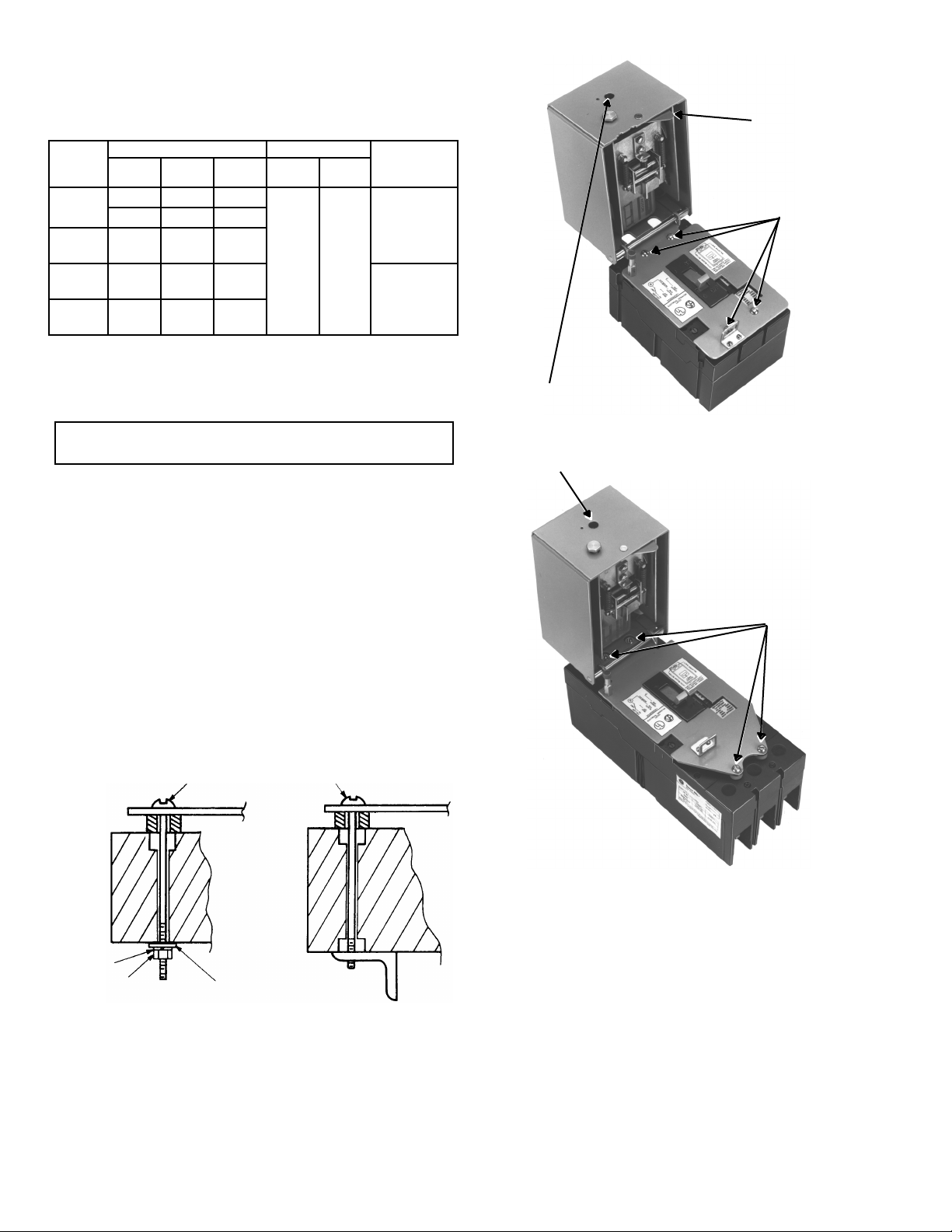
Mounting
Screws
Installation
WARNING: The circuit breaker must be de-energized
before the motor operator is installed.
1. Mount the circuit breaker using the diagonal
mounting screw locations.
2. Connect the line and load circuit breaker terminals.
3. Install the motor operating mechanism using the
remaining diagonal mounting screw locations,
shown in Figure 2. See Figure 3 for alternate
mounting methods.
4. Align the racking mechanism and the circuit
breaker handle by rotating the lead screw or by
moving the breaker handle. Close the cover.
5. Electrically test the mechanism according to the
specifications in Table 1. Refer to Figure 5 for a
schematic and auto reset diagram.
10-32 x 4.25 Screw (E Frame)
10-32 x 6 Screw (F Frame)
Rotate Lead
Screw Assembly
to Align Racking
Mechanism with
Circuit Breaker
Handle
Type
SF250
Type
SE150
Mounting
Screws
Lock
Washer
Nut
Breaker Supported
by Bus Structure
Figure 2. Mounting the motor-operated mechanism on the breaker.
Flat Washer
Breaker Supported
Figure 3. Breaker mounting methods.
Page 3

Figure 4. Outline drawings.
Page 4

oto
Mechanism
Switch
Yellow–ON
Interlock
Switch
Push-Button
Control Station
NOTE: When
using automatic
reset, the ON
push-button must
be SPDT type
and wired as
shown.
Limit
This Line
Automatic
Reset Only
M
rMotor-Operated
Black–Common
Red–OFF
Auto/Reset not
Intended for Use
on dc Applications
Green
Grd
L1
L2
Fuses
For Trip Indication
Use Circuit Breaker
with Internal Bell
Alarm Switch
For Automatic Reset and ON
& OFF Lights Use Circuit
Breaker with Internal
Auxiliary Switch
Indication Lights
(Supplied by Customer)
Customer-
Supplied
Equipment
Figure 5. Wiring diagram for SE/SF Motor-Operated Mechanism.
(All switch contacts are shown with the circuit breaker in the ON position.)
These instructions do not cover all details or variations in equipment nor do they provide for every possible contingency that
may be met in connection with installation, operation, or maintenance. Should further information be desired or should
particular problems arise that are not covered sufficiently for the purchaser’s purposes, the matter should be referred to the
GE Company.
g
GE Industrial Systems
General Electric Company
41 Woodford Ave., Plainville, CT 06062
GEH5613 R01 0989 © 1989 General Electric Company
 Loading...