

Page 1
GE Energy
Industrial Solutions
GEH-6257 Installation Instructions
Distribution Cable
Terminal Block
For Spectra® RMS Molded-Case Circuit Breakers
TM
with microEntelliGuard
, MicroVersaTrip® PM or MicroVersaTrip® Plus Trip Units
For Catalog Number SDCTBA11
Circuit Breaker Accessory
Spectra
MicroVersaTrip
• Control power (+24vdc)
• Control power (-common)
• System communications (Comm. +)
• System communications (Comm. -)
• Breaker position (Aux. Switch red)
• Breaker position (Aux. Switch white)
• Voltage A φ (must be from Voltage Module or Voltage
Conditioner Plate or Voltage Conditioner Assembly)
• Voltage B φ (must be from Voltage Module or Voltage
Conditioner Plate or Voltage Conditioner Assembly)
• Voltage C φ (must be from Voltage Module or Voltage
Conditioner Plate or Voltage Conditioner Assembly)
• Neutral current sensor - black (for equipment
ground fault)
• Neutral current sensor - white (for equipment
ground fault)
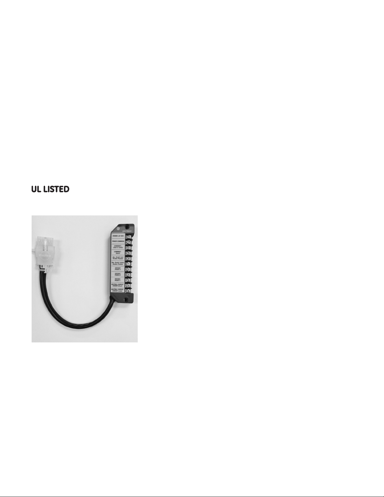
Overview
The General Electric Distribution Cable Terminal Block
is a modular attachment primarily used to provide an
alternate means of connecting input/output signals
to Spectra
microEntelliGuard
Units. The terminal block connection points are as
follows:
®
RMS Molded-Case Circuit Breakers with
TM
or MicroVersaTrip® PM/Plus Trip
Spectra® RMS Breaker with MicroVersaTrip® Plus or
microEntelliGuard
• Control power (+24vdc)
• Control power (-common)
• Neutral current sensor - black (for equipment
ground fault)
• Neutral current sensor - white (for equipment
ground fault)
®
RMS Breaker with microEntelliGuardTM or
®
PM Trip Unit
1
1
TM
(with Basic Metering) Trip Unit
1
1
1
Neutral current sensor input is required for 3Ø/4W or 1Ø/3W systems.
For 3Ø/3W systems do not make any connections.
Page 2
GEH-6257 Installation Instructions
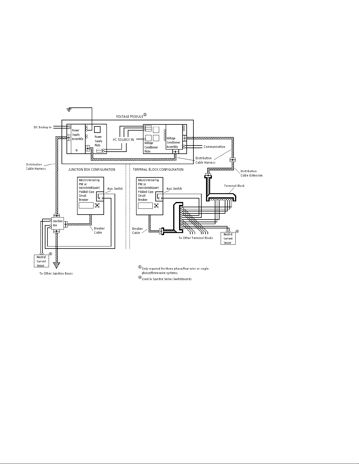
Figure 1 shows how the Distribution Cable Terminal Block is used in a typical MicroVersaTrip® PM system.
®
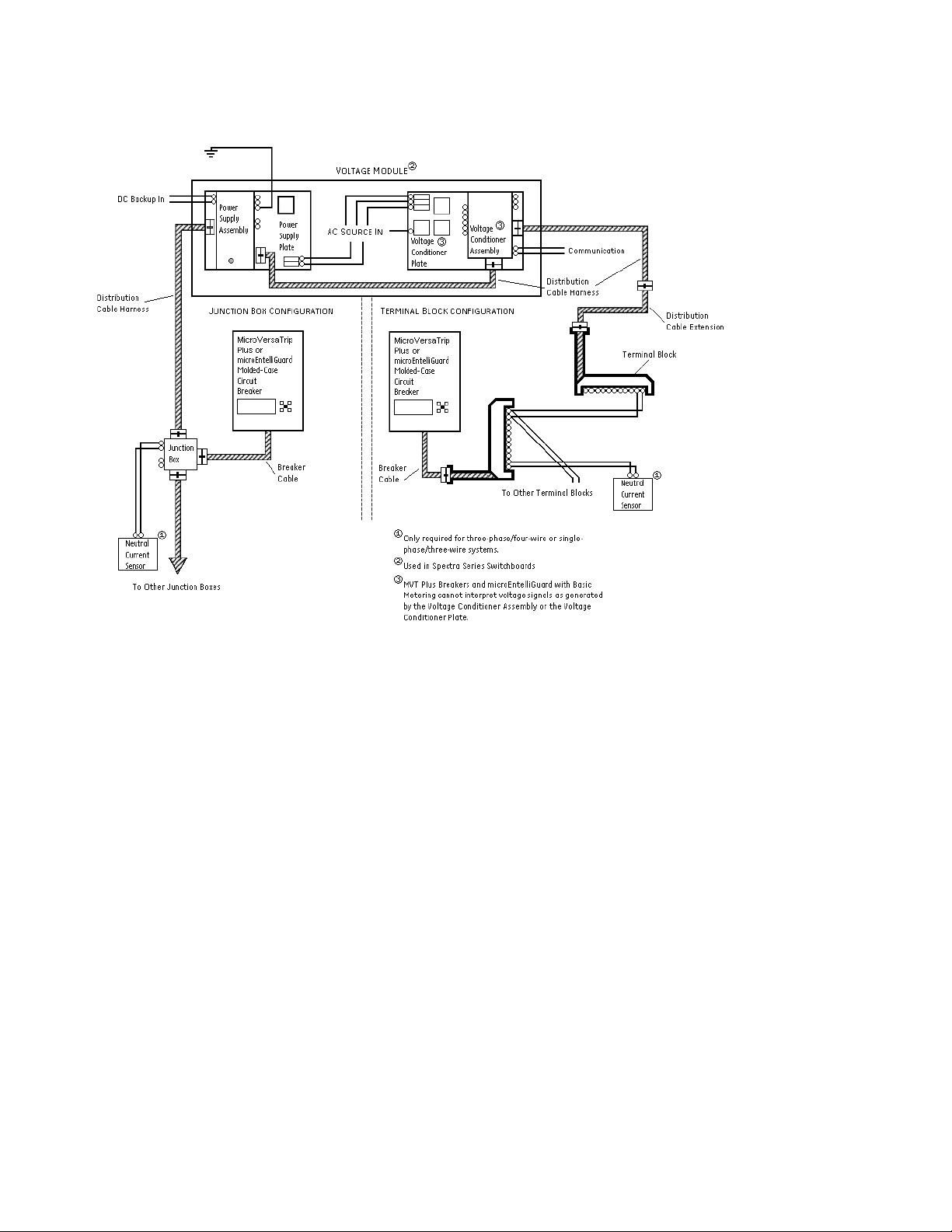
Figure 2 shows how the Distribution Cable Terminal Block is used in a typical MicroVersaTrip
microEntelliGuard
TM
Trip Unit can be used with either configuration, i.e. Figure 1 or Figure 2. The connection
Plus system. The
diagram shown in Figure 2 applies to microEntelliGuardTM Trip Units with Basic Metering.
Figure 1. Typical MicroVersaTrip® PM Trip Unit System detailing the Distribution Cable Terminal Block.
Page 3
GEH-6257 Installation Instructions
Figure 2. Typical MicroVersaTrip® Plus Trip Unit System detailing the Distribution Cable Terminal Block.
Page 4

GEH-6257 Installation Instructions
The Distribution Cable Terminal Block can also be used
to provide a connection into or out of the Distribution
Cable System. The system is used to carry a variety
®
of electronic signals between Spectra
Case Circuit Breakers with microEntelliGuard
®
MicroVersaTrip
PM/Plus Trip Units and Distribution
RMS Molded
TM
or
Cable accessories. The electronic signals supported
by the Distribution Cable System vary depending on
the type of molded-case circuit breaker used; a list of
supported signals appears below.
®
Spectra
MicroVersaTrip
RMS Breaker with microEntelliGuardTM or
®
PM Trip Unit
• Control power (+24vdc)
• Control power (-common)
• System communications (Comm. +)
• System communications (Comm. -)
• Voltage A f (must be from Voltage Module or Voltage
Conditioner Plate or Voltage Conditioner Assembly)
• Voltage B f (must be from Voltage Module or Voltage
Conditioner Plate or Voltage Conditioner Assembly)
• Voltage C f (must be from Voltage Module or Voltage
Conditioner Plate or Voltage Conditioner Assembly)
®
Spectra
microEntelliGuard
RMS Breaker with MicroVersaTrip® Plus or
TM
(with Basic Metering) Trip Unit
• Control power (+24vdc)
• Control power (-common)
Figure 3 shows the individual breaker input connector
pinout for the Distribution Cable Terminal Block for
each type of trip unit, and Figure 4 shows the system
connector pinout for the Distribution Cable Terminal
Block for each type of trip unit.
To use the Distribution Cable Terminal Block to provide
a connection into or out of the Distribution Cable
System, you must use one of the Distribution Cable
Harnesses (cat. nos. SDCHA11, SDCHA30 or SDCHA60
as a jumper into a Distribution Cable Junction Box (cat.
no. SDCJBA).
A Distribution Cable Terminal Block dimensioned
drawing is provided in Figure 5 to assist in mounting the
accessory.
Figure 3. End view of Distribution Cable Terminal Block detailing available breaker input pinout connections.
Figure 4. End view of Distribution Cable Terminal Block detailing available system pinout connections.
Page 5

GEH-6257 Installation Instructions
Figure 5. Dimensioned drawing of the Distribution Cable Terminal Block (dimensions shown in inches).
Figure 6 contains a point-to-point wiring diagram for a Distribution Cable Terminal Block connected to a Spectra®
®
RMS Molded-Case Circuit Breaker with a MicroVersaTrip
diagram for a Distribution Cable Terminal Block connected to a Spectra
®
MicroVersaTrip
PM Trip Unit. The microEntelliGuard
Figure 7. The connection diagram shown in Figure 6 applies to microEntelliGuard
Plus Trip Unit. Figure 7 contains a point-to-point wiring
®
TM
Trip Unit can be used with either configuration, i.e. Figure 6 or
RMS Molded-Case Circuit Breaker with a
TM
Trip Units with Basic Metering.
Figure 6. Wiring connections to the Distribution Cable Terminal Board for a Spectra® RMS breaker with a MicroVersaTrip® Plus Trip Unit.
Page 6

GEH-6257 Installation Instructions
Figure 7. Wiring connections to the Distribution Cable Terminal Board for a Spectra® RMS breaker with a MicroVersaTrip® PM Trip Unit.
Page 7

GEH-6257 Installation Instructions
Connections
The screw terminals on the Distribution Cable Terminal
Board are labeled by function for clarity. The terminal
strip pocket will accommodate a spade lug or ring
terminal with a tongue width up to 0.320 inches. The
terminal screw size is 10-32. To make the connection,
attach an appropriate spade lug or ring terminal to the
wire, slip the fastener beneath the terminal screw and
tighten.
The Distribution Cable Terminal Block also contains a
cable with a 12-pin plug connector. This connector is
keyed so it cannot be inserted incorrectly into a mating
12-pin receptacle connector.
To connect the end of the Distribution Cable Terminal
®
Block to a Spectra
with a microEntelliGuard
RMS Molded-Case Circuit Breaker
TM
or a MicroVersaTrip® PM/Plus
Trip Unit with a breaker cable or another Distribution
Cable Accessory, align the plug hook connector of
the Distribution Cable Terminal Block with the mating
receptacle interlock and insert the plug into the receptacle
until the interlock and hook catch (or click), see Figure 8.
To disconnect the Distribution Cable Terminal Block,
press down at the rear of the receptacle interlock until
the interlock clears the plug hook and remove the plug
(see Figure 9).
Additional Information
Refer to these other user’s manuals for more details:
GEH-5934 MicroVersaTrip® Plus and MicroVersaTrip®
®
PM Trip Units in Spectra
RMS Molded-
Case Circuit Breakers
GEH-700 Spectra® G Breaker w/
EntelliGuard™ Trip Unit
micro
GEH-701 Spectra® K Breaker w/
EntelliGuard™ Trip Unit
micro
GEH-702 microEntelliGuard™ Trip Unit Users
Manual
DEH-41318 Universal Rating Plug
GEH-6250 Voltage Module
GEH-6251 Power Supply Plate
GEH-6252 Voltage Conditioner Plate
GEH-6253 Power Supply Assembly
GEH-6254 Voltage Conditioner Assembly
GEH-703 MET Battery Pack Adapter
GEH-704 MET Advanced Distribution Cable
Junction Box
DEH-006 Distribution Cable Junction Box
GEH-705 MET Distribution Cable Extension (20-pin)
GEH-6256 Distribution Cable Extension (12-pin)
GEH-6255 Distribution Cable Harness (12-pin)
GEH-706 MET Distribution Cable Terminal Blocks
(11 point & 22 point)
GEH-6491 POWER LEADER™ Modbus Concentrator
GEH-6502 POWER LEADER™ PMCS 5.0 Network
Architecture Guide
GEH-707 MET Sealable Cover kits
DEH-4568 GTU digital test kit (GTUTK20)
GEH-5551 Shunt Trip and UVR instructions
GEH-5593 Aux switch and bell alarm
GEK-64467 TIM-1 Zone Selective Interlock Module
Figure 8. Side view of plug-receptacle connection insertion.
Figure 9. Side view of plug-receptacle connection removal.
Page 8

Spectra and MicroVersaTrip are registered trademarks and EntelliGuard and
microEntelliGuard are trademarks of the General Electric Company.
These instructions do not cover all details or variations in equipment nor do they
provide for every possible contingency that may be met in connection with installation,
operation, or maintenance. Should further information be desired or should particular
problems arise that are not covered sufficiently for the purchaser’s purposes, the
matter should be referred to the GE Company.
GE Energy
41 Woodford Avenue, Plainville, CT 06062
www.geelectrical.com
© 2012 General Electric Company
imagination at work
GEH-6257 Rev. 5 (8/13)
 Loading...