

Page 1
GE Energy
Industrial Solutions
GEH-704 Installation Instructions
Advanced Distribution Cable
Junction Box
For Spectra® RMS Molded-Case Circuit Breakers
TM
with Advanced Feature microEntelliGuard
Trip Units
For Catalog Number SDCJBBC
Circuit Breaker Accessory
Overview
The General Electric Advanced Distribution Cable
Junction Box is a modular connector used to provide
quick, easy and reliable attachment of Spectra
Molded-Case Circuit Breakers with microEntelliGuard
Trip Units to the Distribution Cable System. The
electronic signals supported by the Advanced
Distribution Cable Junction Box appear below.
®
Input/output signals to Spectra
microEntelliGuard
• control power (+24vdc)
• control power (common)
• voltage A f (must be from Voltage Module or Voltage
Conditioner Plate or Voltage Conditioner Assembly)
• voltage B f (must be from Voltage Module or Voltage
Conditioner Plate or Voltage Conditioner Assembly)
• voltage C f (must be from Voltage Module or Voltage
Conditioner Plate or Voltage Conditioner Assembly)
TM
Trip Unit
RMS Breaker with
®
RMS
• neutral current sensor - black (for equipment ground
fault)
• neutral current sensor - white (for equipment ground
TM
fault)
• breaker position (via installed aux. switch - red wire)
• breaker position (via installed aux. switch - white wire)
• system communications (Comm +)
• system communications (Comm –)
• zone select interlock (ZSI O –)
• zone select interlock (ZSI O +)
• zone select interlock (ZSI I –)
• zone select interlock (ZSI I +)
• reduced energy let-through (RELT I –)
• reduced energy let-through (RELT I +)
• ground fault alarm (GFA/PC1 O –)
• ground fault alarm (GFA/PC1 O +)
• reduced energy let-through (RELT/PC2 O –)
• reduced energy let-through (RELT/PC2 O +)
1
1
1
Neutral current sensor input is required for 3Ø /4W or 1Ø /3W systems. For 3Ø /3W systems, do not make any connections.
Page 2
GEH-704 Installation Instructions
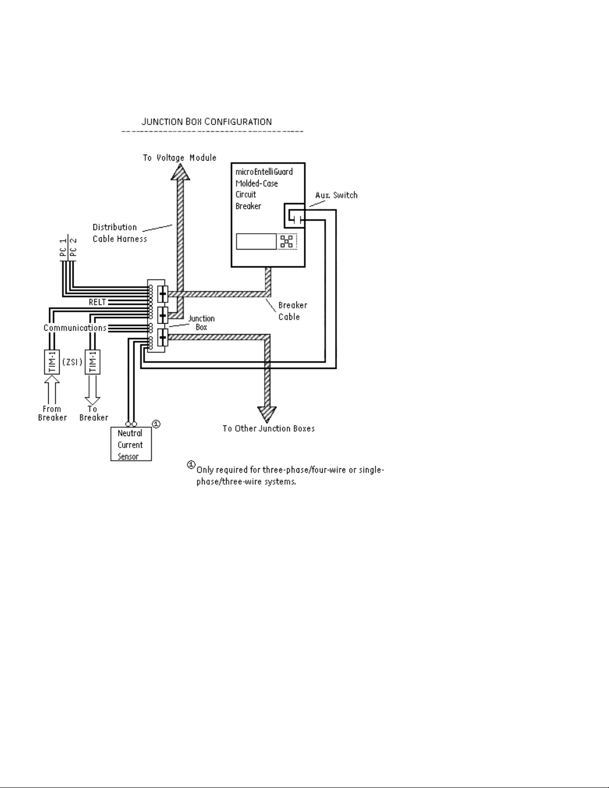
Figure 1 shows how the Advanced Distribution Cable Junction Box is used in a typical microEntelliGuardTM system.
Figure 1. Typical microEntelliGuardTM Trip Unit (using 20-pin connector) system.
Page 3

GEH-704 Installation Instructions
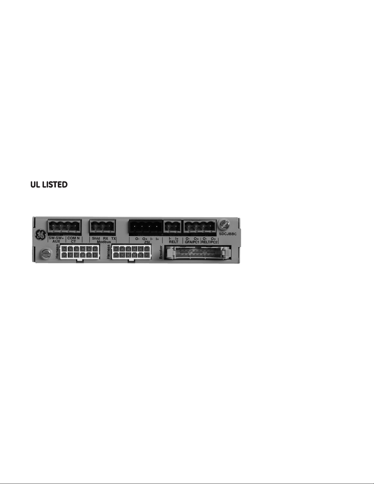
The Advanced Distribution Cable Junction Box has a 20pin plug connector on the front face labeled “BREAKER”.
This connector mates to the 20-pin receptacle
®
connector of the Spectra
Breaker with a microEntelliGuard
RMS Molded-Case Circuit
TM
Trip Unit. Figure 2
shows this “BREAKER” input connector pinout for the
Advanced Distribution Cable Junction Box.
The Advanced Distribution Cable Junction Box also
has two 12-pin plug connectors on the front face
labeled “HARNESS”. These connectors mate with the
12-pin receptacle connectors of a Distribution Cable
Harness (cat. nos. SDCHA11, SDCHA30 or SDCHA60). By
connecting to these plugs, the Advanced Distribution
Cable Junction Box provides a connection into or
out of the Distribution Cable System. Figure 3 shows
the “HARNESS” connector pinout for the Advanced
Distribution Cable Junction Box.
Figure 3. HARNESS pinout connections for the Advanced
Distribution Cable Junction Box.
The system is used to carry a variety of electronic signals
®
between Spectra
with microEntelliGuard
RMS Molded-Case Circuit Breakers
TM
Trip Units and Distribution
Cable accessories. The electronic signals supported by
the Distribution Cable System are as follows.
Figure 2. BREAKER input pinout connections for the Advanced
Distribution Cable Junction Box.
Spectra
®
RMS Breaker with microEntelliGuardTM
Trip Unit
• control power (+24vdc;)
• control power (common)
• voltage A f (must be from Voltage Module or Voltage
Conditioner Plate or Voltage Conditioner Assembly)
• voltage B f (must be from Voltage Module or Voltage
Conditioner Plate or Voltage Conditioner Assembly)
• voltage C f (must be from Voltage Module or Voltage
Conditioner Plate or Voltage Conditioner Assembly)
Page 4

GEH-704 Installation Instructions
Dimensions and Wiring Diagrams
An Advanced Distribution Cable Junction Box dimensioned drawing is provided in Figure 4 to assist
in mounting the accessory.
Figure 4. Dimensioned Drawing of the Advanced Distribution Cable Junction Box (dimensions shown in inches).
Page 5

GEH-704 Installation Instructions
Figure 5 contains a point-to-point wiring diagram for an Advanced Distribution Cable Junction Box connected
®
to a Spectra
RMS Molded-Case Circuit Breaker with a microEntelliGuardTM Trip Unit.
Figure 5. Wiring and power connections to the Advanced Distribution Cable Junction Box for a Spectra® RMS breaker
with a microEntelliGuard
TM
Trip Unit.
Page 6

GEH-704 Installation Instructions
Connections
The Advanced Distribution Cable Junction Box has five
additional connectors, which are labeled by function
for clarity. The four-pin receptacle is used for the
connection of a neutral current sensor signal (2 pins)
and an auxiliary switch signal (2 pins) into the breaker.
The three-pin terminal block is for the communication
wiring. The black four-pin terminal is used for the input
and output connections for zone selective interlock
(ZSI), the two-pin connector is used for the input of
reduced energy let-through (RELT) wiring, and the last
four-pin receptacle is used for ground fault alarm (GFA)
and RELT output connections.
®
Note: If the Spectra
with a microEntelliGuard
RMS Molded-Case Circuit Breaker
TM
Trip Unit has the ground
fault option AND is connected to either a three phase/
four wire system or single phase/three wire system,
then a neutral input is required for the circuit breaker to
function properly. A Neutral CT is also required for Trip
Units optioned with neutral protection.
Table 1. Neutral Transformers
Breaker Type
SG 400 TSRG204
SK
Breaker Current Sensor
Rating (S)
150 TSRG201
600 TSRG206
800 TSKG408
1200 TSKG412
Catalog Number
Auxiliary Switch
®
Spectra
microEntelliGuard
RMS Molded-Case Circuit Breakers with
TM
Trip Units require an auxiliary
switch mounted in the right side accessory pouch to
provide a breaker position signal via communication
network. The switch is a form C contact and is used to
convey breaker position (closed or open). This position
input signal is accomplished by connecting the red and
white auxiliary switch leads to the two screw terminals
of the plug connector. This connector is then plugged
into the front face of the 4-pin receptacle of the
Advanced Distribution Cable Junction Box labeled “AUX
SW-” (white) and “AUX SW+” (red).
The connectors are a .200" on-center European
Style receptacle such that stripped wire (AWG #12-
26) can be used. The recommended torque for the
connector screws is 5 in-Ibs. This connector is keyed
to help prevent incorrect mating. When connecting
to the four-pin connectors, it is recommended that
two 2-pin connectors be used, one for auxiliary
switch connections, one for neutral current sensor
connections, etc… (although one 4-pin may be used).
Neutral
A Neutral CT is required for advanced features such
as ground fault, ground fault alarm, and neutral
protection. The neutral input is accomplished by
connecting a neutral current sensor between the
system neutral (line) and breaker neutral (load), then
wiring the BLACK and WHITE neutral current sensor
screw terminals to the two screw terminals of the
plug connector. This junction box connector is then
plugged into the front face of the 4-pin receptacle of
the Advanced Distribution Cable Junction Box labeled
“CT COM” (white wire) and “CT N” (black wire). Available
neutral transformers are shown in the following table.
Note: The microEntelliGuard™ Trip Unit requires an
Auxiliary Switch with gold plated contacts
(Use table below).
Table 2. Auxiliary Switches
Catalog Number No. of Switch Elements Switch Rating
SAUXGAB1 1 form C
SAUXGAB2 2 form C
Gold-Plated Contacts
0.5 A @ 30 V
Modbus Communications
Spectra
®
RMS Breakers with microEntelliGuardTM
Trip Units communicate via a modbus link, which is
accomplished by connecting the clear, black, and shield
leads of AWG #16 twisted shielded wire (Belden 9841) to
the three screw terminals on the Advanced Distribution
Cable Junction Box labeled Modbus RX, Modbus TX, and
Modbus Shld. Communication links between similar
breakers may be daisy chained between Advanced
Distribution Cable Junction Boxes (refer to Figure 5).
The wiring should begin at the master device and wire
from device to device. At the end of the wiring chain
the last connection should be to the Multilin Modbus
terminator (RC network part number is 1810-0106).
The Tx connection should connect to other Mod-bus Tx
(+) connections. The Rx connection should connect to
other Modbus Rx (-) connections.
Page 7

GEH-704 Installation Instructions
Important: Modbus links (microEntelliGuard™ may not be
directly connected to Commnet links (MicroVersaTrip®).
Commnet connections must run through a Modbus
concentrator before connected to a Modbus signal.
Zone Selective Interlock (ZSI)
The ZSI signals are connected to terminals 8-11 (Refer
back to Figure 4 for terminal connector reference
#’s). The ZSI inputs and outputs are used to setup
coordination with other breakers. The interface
between the Spectra RMS breaker and additional
breakers is accomplished through the TIM1 module.
Ground Fault Alarm (GFA)
If the unit is configured for GFA, terminals 14 & 15
(Figure 4) are used to indicate the ground fault.
These terminals are dry contact outputs with a 1
amp maximum capability. If the unit does not have
ground fault, terminals 14 & 15 (Figure 4) are used as
a programmable alarm output. The 1 amp maximum
applies in this situation also.
Figure 6. Side view of breaker cable-junction box insertion and
attachment.
To connect a Distribution Cable Harness (12-pin) to the
Advanced Distribution Cable Junction Box, insert the
receptacle into the plug until the interlock and hook
catch (see Figure 7). The 12-pin connectors are keyed
so they cannot be inserted incorrectly into a mating
12-pin receptacle connector. To disconnect from the
Advanced Distribution Cable Junction Box, press down
at the rear of the receptacle interlock until the interlock
clears the plug hook and withdraw the receptacle
interlock (see Figure 9).
Reduced Energy Let-Through (RELT)
The RELT system is used to put breakers in a
reduced energy mode for service and preventative
maintenance. RELT has an input and an output. To enter
RELT mode, 24 volts (AC or DC) is applied to terminals
12 & 13 (Figure 4). If DC is used, observe the polarity
markings on the Advanced Distribution Junction Box.
Terminals 16 & 17 (Figure 4) provide a dry contact
output signal to indicate RELT mode has been activated.
These are 1 amp maximum dry contacts.
If RELT is not optioned in the breaker the RELT
signals can be used as programmable inputs and
programmable outputs to the breaker.
The Advanced Distribution Cable Junction Box also
contains two 12-pin plug connectors and one 20-pin
®
connector. To connect a Spectra
RMS Molded-Case
Circuit Breaker to the Advanced Distribution Cable
Junction Box, align the 20-pin breaker receptacle
interlock connector with the mating “BREAKER” plug
hook connector of the Advanced Distribution Cable
Junction Box and lock the two hinged interlocks into the
connector (See Figure 6).
Figure 7. Side view of a receptacle-plug connection insertion.
Note: If the Distribution Cable Harness has a plastic
hinge on the strain relief, then cut this hinge off, as it
will interfere with other Junction Box Connectors (see
Figure 8).
Page 8

GEH-704 Installation Instructions
Figure 8. Cable Harness Strain Relief. Dotted line shows
approximate location for cutoff.
Figure 9. Side-view of a receptacle-plug connection removal
Additional Information
Refer to these other publications for additional
information.
®
GEH-5934 MicroVersaTrip
PM Trip Units in Spectra
Plus and MicroVersaTrip®
®
RMS
Molded-Case Circuit Breakers
®
GEH-700 Spectra
G Breaker w/
microEntelliGuard™ Trip Unit
®
GEH-701 Spectra
K Breaker w/
microEntelliGuard™ Trip Unit
GEH-702 microEntelliGuard™ Trip Unit Users
Manual
DEH-41318 Universal Rating Plug
GEH-6250 Voltage Module
GEH-6251 Power Supply Plate
GEH-6252 Voltage Conditioner Plate
GEH-6253 Power Supply Assembly
GEH-6254 Voltage Conditioner Assembly
GEH-703 MET Battery Pack Adapter
DEH-006 Distribution Cable Junction Box
GEH-705 MET Distribution Cable Extension (20-pin)
GEH-6256 Distribution Cable Extension (12-pin)
GEH-6255 Distribution Cable Harness (12-pin)
GEH-706 MET Distribution Cable Terminal Blocks
(11 point & 22 point)
GEH-6257 Distribution Cable Terminal Block (11 point)
GEH-707 MET Sealable Cover kits
DEH-4568 GTU digital test kit (GTUTK20)
GEH-5551 Shunt Trip and UVR instructions
GEH-5593 Aux switch and bell alarm
GEK-64467 TIM-1 Zone Selective Interlock Module
Spectra and MicroVersaTrip are registered trademarks and EntelliGuard and
microEntelliGuard are trademarks of the General Electric Company.
These instructions do not cover all details or variations in equipment nor do they
provide for every possible contingency that may be met in connection with installation,
operation, or maintenance. Should further information be desired or should particular
problems arise that are not covered sufficiently for the purchaser’s purposes, the
matter should be referred to the GE Company.
GE Energy
41 Woodford Avenue, Plainville, CT 06062
www.geelectrical.com
© 2012 General Electric Company
imagination at work
GEH-704 Rev. 6 (10/12 M45)
 Loading...