

Page 1

06/06/2005
Addendum #1 to GEK-39672G
Instructions for making bus connections across shipping split sections
Introduction
PowerVac switchgear is shipped in splits of one, two, three or four stacks. When
connecting shipping splits together it may be required to make the connections across the
main bus or the tie bus. The main bus can be accessed from the front of the gear through
the breaker compartment and the tie bus can be accessed from the rear. Breakers and
rollouts should be removed from the switchgear before the bus connections can be made
across the shipping split.
This addendum supplements the instructions provided in the main body of the instruction
book in pages 28 to 32. Ground bus connections across shipping splits shall be made as
specified in page 35 of the instruction book.
WARNING : All primary and secondary circuit devices must be de-energized and the
primary circuit grounded before undertaking any work on the switchgear.
Main bus connections across the shipping split
Step – 1, Remove horizontal barrier
A horizontal barrier located between the front upper and lower compartments has to be
removed. This barrier is shown in Fig – A(1)-1.
If heaters are provided, the heater shown in Fig – A(1)-1 will have to be removed in order
to remove the horizontal barrier.
Do not remove the pan on which the breaker ground shoe is located. Item # 4 in Fig –
A(1)-1. In most cases the pan shown as item #4 will have a cover over it ( cover not
shown in Fig A(1)-1). It is not required to remove the cover.
Page 2
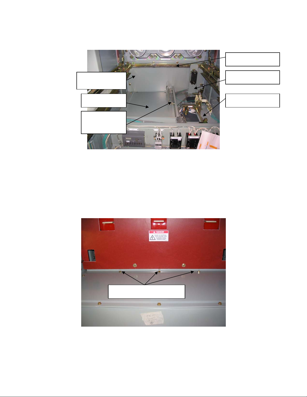
(
(6) Do not remove
(3) Remove
later)
(2) Remove
(1) Remove
heater
Fig – A(1)-1
Front upper compartment
For stacks that have a 2 High PT/CPT tray in the front upper compartment, the procedure
for removing the horizontal barrier is different from that shown above. For such stacks,
remove the three taptites ( self threading bolts ) shown in Fig A(1)-2 in the front upper
compartment. When these taptites are removed, the barrier underneath shown in Fig –3
can be removed.
(5) Do not remove
(4) Do not remove
Remove these three taptites
Fig A(1) - 2
Front upper compartment intended for 2-High rollouts
51
Page 3
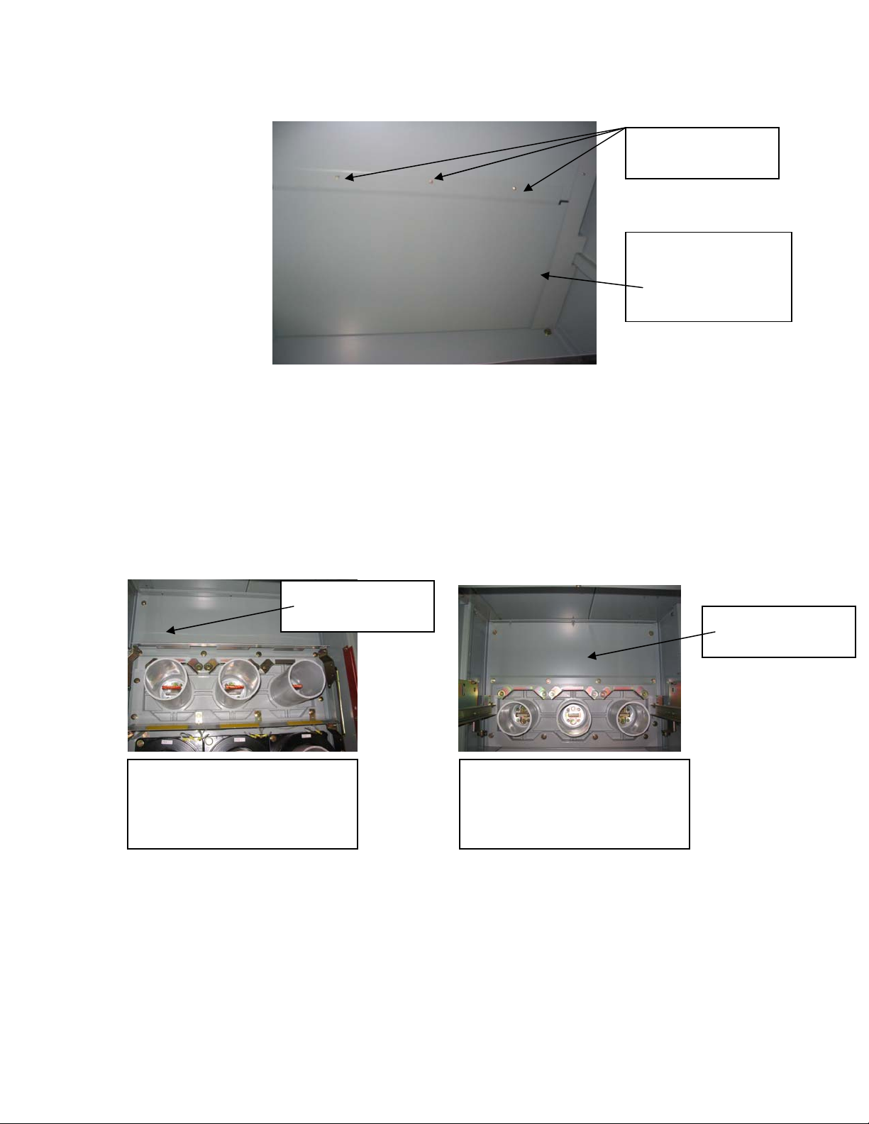
p
p
The underside of
the taptites
This barrier can be
removed when the 3
taptites are removed.
Fig – A(1)-3
View looking up into the front bottom compartment of a 2 High-A rollout stack
Step – 2, Remove vertical mid barrier in front lower compartment
Remove the vertical mid barrier located in the upper part of the lower front compartment.
This barrier is located approximately 49 inch from the front of the stack. See Fig – A(1)4a for identification of barrier in the breaker compartment and A(1)-4b for identification
of barrier in a PT/CPT rollout compartment
Remove this
barrier
Fig A(1)-4a
View looking into typical
front lower breaker
artment
com
Step – 3, Remove vertical mid barrier in front upper compartment
Remove the vertical mid barrier located in the lower part of the upper front compartment.
This barrier is located approximately 49 inch from the front of the stack. See item # 3 of
View looking into typical
front lower PT/CPT rollout
Fig A(1)-4b
artment
com
Remove this
barrier
52
Page 4
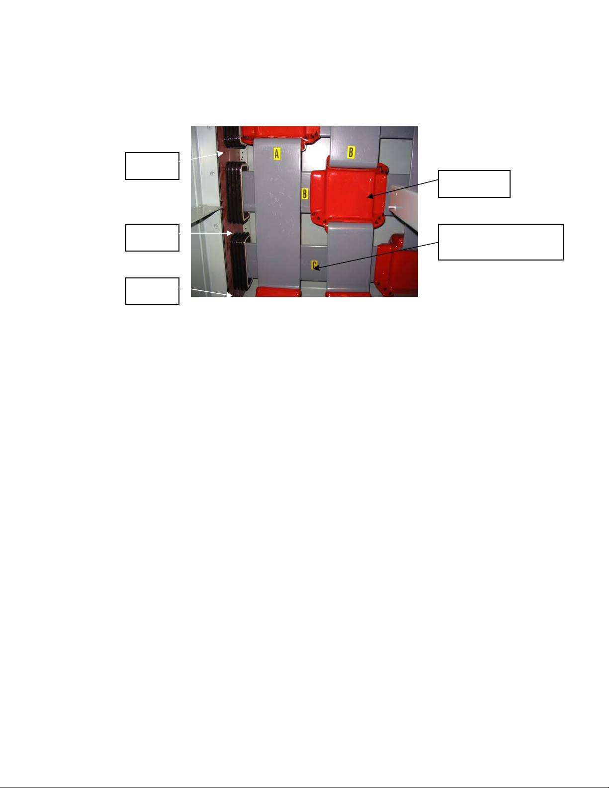
Fig – A(1)-1. Do not remove the secondary disconnect block ( item # 5 ) or the chain (
item # 6 ). This barrier can be removed by sliding it down. This will expose the main bus
compartment as shown in Fig – A(1)-5
Tape
Boots
Tape
Tape
Fig – A(1)-5
View looking into main bus compartment from the front
( Porcelain inter-unit bus supports )
Step – 4, Remove glastic shipping supports
Unbolt and remove the glastic shipping supports taking care to ensure that splice plates
and spacers provided in the bus joint do not fall off. Loosely refasten bus hardware to
hold the splice plates and spacers in place. Discard the shipping supports. The red
insulating boots will have to be removed to access the bolts for the shipping supports.
The boots are held together using plastic re-useable pull-apart fasteners.
Step –5a, Remove inter-unit bus supports ( Go directly to step 5b if polyester glass bus
supports are provided)
a) Apply strong adhesive tape so as to keep the two glastic supports together
temporarily. The tape may be applied in 4 places – above, below and between the
porcelain bus supports. See Fig A(1)-5 and Fig A(1)-6. In Fig A(1)-6, the bus
support is shown outside the switchgear to get good picture clarity. It is not
required to remove the bus supports out of the switchgear.
b) Remove the ¼ - 20 fasteners used to mount the bus support to the side sheet.
There should be 4 ( 2 for poly glass) on the top and 4 ( 2 for poly glass ) at the
bottom. The hex nut should be towards the outside on the left hand side of the
side sheet.
c) Gently remove the bus support assembly away from the side sheet and into the
bus compartment. Let it rest temporarily in a vertical position inside the bus
compartment.
Copper Main bus or
Glastic shipping supt.
53
Page 5
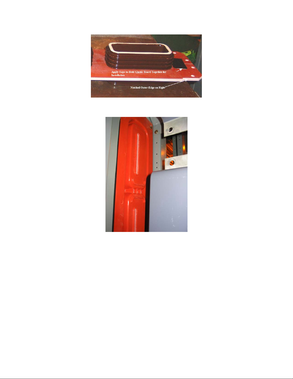
Fig – A(1)-6
Location of tape
Fig A(1)-7
Typical Bus compartment with polyester glass inter-unit bus support
Step – 6 Align switchgear stacks
a) Gently align the next stack on the left with this stack taking care not to damage
the porcelain bus supports.
b) When the eight bus support holes ( four holes for polyester glass bus supports )
are aligned, replace the bus support assembly against the side sheet and use the ¼
- 20 hardware to fasten the bus supports and the two side-sheets together as shown
in Fig A(1)-8
c) A black rubber gasket is provided to cover the edge of the side sheets around the
perimeter of the bus pass-through cutout for 15kV gear. It should be ensured that
this gasket is in place.
54
Page 6

Fig – A(1)-8
View showing stacks bolted together
Step – 7, Make bus connections ( for polyester glass bus supports go directly to step 7c )
a) Position the rubber cushion so that it is approximately in the center of the
porcelain support. Apply RTV sealant ( 0282A3566P005 ) around the rubber
cushion to hold it in place.
b) Gently insert the main bus through the bus support taking care not to break or
chip the porcelain. The main bus should pass through a rubber bus cushion
located inside the porcelain bus support. If the rubber bus cushion falls off, reinsert the cushion on the busbar as shown in Fig – A(1)-9 and pass the busbar
through the porcelain support.
c) For polyester glass inter-unit bus supports insert the bus through the
corresponding slots in the orange polyester glass material.
d) Make main bus connections at the bus joint. The main bus should be inserted into
its vacant slot between the splice plates. The bus should line up with the main bus
coming into the joint from the other side.
e) Tighten bus connections to between 30 and 35 ft-lb.
55
Page 7

Fig – A(1)-9
Shows rubber cushion inserted over bus
Step 8, Finishing up
a) Re-assemble the boots that were removed in step 4.
b) Remove tape applied in step 5a ( for porcelain only )
c) Ensure that no tools or other material is left behind in the bus compartment
d) Re-assemble the vertical mid-barriers and the horizontal pan that were removed
in steps 1 to 3
e) Before energizing the switchgear conduct Insulation resistance (Megger) and HV
Hipot tests ( optional ) as described in the instruction books.
56
Page 8

Tie bus connections across the shipping split
Steps 4 through 8 are the same for making the tie bus connections. The tie bus
compartment can be accessed from the rear of the switchgear by removing the rear bus
barrier of the tie bus compartment. Fig – A(1)-10 shows a typical bottom tie bus
compartment with the rear bus barrier removed.
Fig – A(1)-10
Typical Rear tie bus compartment with the rear bus barrier removed.
If the tie bus compartment has 2 inch x ¼ inch aux bus running between stacks, inter-unit
bus supports are not required and will not be provided.
57
Page 9

06/06/2005
Addendum #2 to GEK-39672G
Instructions for bolting stacks together across shipping split sections
Introduction
PowerVac switchgear is shipped in splits of one, two, three or four stacks. This
instruction provides details on bolting the stacks together across the shipping splits. This
instruction is applicable to indoor, indoor drip proof and outdoor switchgear. However,
for indoor drip proof and outdoor construction additional assembly instructions for
connecting the roof and aisle sections are provided in the INSTALLATION section of
this instruction book.
WARNING : All primary and secondary circuit devices must be de-energized and the
primary circuit grounded before undertaking any work on the switchgear.
All breakers have to be racked out and PT/CPT rollouts have to be drawn out of the
shipping split stacks before proceeding with the inter-unit bolting.
Step – 1, Inter-unit bus connections.
Make inter-unit bus connections as specified in addendum #1 of GEK-39672G.
Step –2, Center-post bolting
Two sets of 0.38 x 3.00 inch hardware and two sets of 0.38 x 3.25 inch hardware are
provided for this purpose. Refer Fig A(2)-1 and Fig A(2)-2.
58
Page 10

Factory connections
Perimeter
bolting
Perimeter
bolting
Center-post ( 4 places)
Fig A(2)-1
Sectional view of inter-unit bolting
Center-post bolting
Fig A(2)-2
Typical Center-post bolting
The center-post bolting has to be done at 2 places in the front upper compartment and at
two places in the front bottom compartment. The 3.25 inch long bolts may be used where
it is required to bolt through the red glastic sheet shown in the upper portion of Fig A(2)–
2.
59
Page 11

Step – 2 Perimeter bolting
Sixteen sets of 0.38 x 1.00 inch hardware is provided for perimeter bolting. The
following guidelines shall be followed :
a) Minimum of 3 bolts on each vertical post
b) For 82 inch deep and 94 inch deep stacks, a minimum of two bolts on each depth
post with at least one bolt in the front compartment and one bolt in the rear
compartment.
c) For 106 inch deep stacks, a minimum of three bolts on each depth post with at
least one bolt in the front compartment and one location in the rear compartment.
Where there are no accessibility issues it is generally recommended that perimeter bolting
be done at all 16 locations.
NOTE : If the units have to be moved or lifted after installation, they should be lifted
only at the shipping splits.
60
Page 12

Page 13

Intentionally Left Blank.
62
Page 14

Intentionally Left Blank.
63
Page 15

 Loading...