

Page 1

g
GEH-6502
POWER LEADER™
Power Management Control System
Network Architecture Guide
Page 2

WARNINGS
CAUTIONS
GEH-6502
WARNINGS, CAUTIONS, AND NOTES
AS USED IN THIS PUBLICATION
Warning notices are used in this publication to emphasize that hazardous voltages,
currents, or other conditions that could cause personal injury exist in this equipment or
may be associated with its use.
Warning notices are also used for situations in which inattention or lack of equipment
knowledge could cause either personal injury or damage to equipment.
Caution notices are used for situations in which equipment might be damaged if care is
not taken or which may cause communication errors to occur.
NOTES
Notes call attention to information that is especially significant to understanding and
operating the equipment.
This document is based on information available at the time of its publication. While
efforts have been made to ensure accuracy, the information contained herein does not
cover all details or variations in hardware and software, nor does it provide for every possible contingency in connection with installation, operation, and maintenance. Features
may be described herein that are not present in all hardware and software systems. GE
Industrial Systems assumes no obligation of notice to holders of this document with
respect to changes subsequently made.
GE Industrial Systems makes no representation or warranty, expressed, implied, or statutory, with
respect to, and assumes no responsibility for the accuracy, completeness, sufficiency, or usefulness of
the information contained herein. No warrantees of merchantability or fitness for purpose shall apply.
©Copyright 2000- 2002 GE Company, all rights reserved.
POWER LEADER™, MicroVersaTrip®, Spectra®, and PowerBreak® are trademarks of GE Company.
®
Modbus RTU
Modbus
is a registered trademark of AEG Schneider Automation.
®
is a registered trademark of Modicon Inc.
Page 3

Power Management Control System
This manual provides an overview of the network
architecture associated with the GE POWER LEADER
Power Management Control System (PMCS). Please
read through this guide prior to laying out a PMCS
network. You must comple te the following steps before
proceeding with the instructions in this manual:
1. Have instruction manuals on hand for all
Intelligent Electronic Devices (IEDs) to be
installed. (See Ap pe ndix B f or a list of in str uction
manuals.)
2. Complete installation of all system IEDs.
• All IEDs mounted.
• All IEDs wired to cont rol power and energize d .
• All IEDs assigned a unique address.
Refer to the appropriate IED instruction manuals
for these procedures.
3. Ensure that the PC serving as the Power
Management Contro l S y stem host is operati onal:
• The RS-485 interface card, RS-232/RS-485
converter, or Ethernet Card is installed and
functioning correctly.
• Any Ethernet Gateways or Modbus
Concentrators are installed and functioning
correctly.
• Windows 2000 SP2 is installed and functioning
correctly.
• The Power Management Control System
software is installed and properly configured.
Getting Started
WARNING: Where personnel or equipment safety is involved, do not rely
exclusively on information reported by the Power Management Control
System or any power management equipment. ALWAYS confirm the status
and safety of electrical power equipment in person by conventional test
IEDs before operating, energizing or working on such equipment.
WARNING: Network wiring and grounding rules described herein apply
primarily to commercial/industrial installations. Substation installations
will exist in the presence of dangerously elevated ground potential relative
to points outside of the station grid as well as large electromagnetic
induction fields. Additionally, large ground faults can elevate substation
ground potentials. Follow local utility best-practices/safety procedures to
prevent risk of shock/electrocution to personnel and damage to
equipment that could result in a loss of protection and communications.
Page 4

Power Management Control System
Getting Started
(This page left blank intentionally.)
Page 5

Power Management Control System
Table of Contents
Preface
Welcome to PMCS!.............................................................................................................................................1
What is Power Management?............................................................................................................................1
Benefits of Power Management.........................................................................................................................1
What is PMCS? ...................................................................................................................................................1
How Does PMCS Work? .....................................................................................................................................2
Using This Guide .................................................................................................................................................2
Chapter 1 – Introduction................................................................................. 3
1–1 Typical Systems...........................................................................................................................................3
1–2 Master-Slave Organization .........................................................................................................................4
1–3 Required Hardware......................................................................................................................................5
Host Computer......................................................................................................................................5
RS-485 Interface Card or RS-232/RS-485 Converter..........................................................................5
Ethernet Network Card........................................................................................................................5
1–4 Compatibility & Interconnection with Existing Ethernet Networks...........................................................5
1–5 Operation During Power Outage.................................................................................................................5
1–6 Time & Date Stamping................................................................................................................................6
1–7 Remote System Operation...........................................................................................................................6
1–8 Supported IEDs ............................................................................................................................................7
Chapter 2 – Network Design...........................................................................9
2–1 Modbus Rules............................................................................................................................................10
2–2 Ethernet Configuration Rules....................................................................................................................11
Table 3. Ethernet configuration rules2–3 Ethernet Network Considerations ................................................12
10Base-T specifications and rules ....................................................................................................13
10Base-FL specifications and rules...................................................................................................13
2–4 Commnet Configuration Rules...................................................................................................................14
2–5 Modbus Wiring Rules – Diagrams............................................................................................................15
2–6 Commnet Wiring Rules – Diagrams..........................................................................................................19
2–7 Performance Recommendations...............................................................................................................21
The Ideal Network..............................................................................................................................21
Modbus performance recommendations..........................................................................................21
Commnet performance recommendations........................................................................................21
2–8 Addressing the IEDs...................................................................................................................................21
2–9 Multiple RS-485 Networks – Addressing.................................................................................................25
2–10 System Expansion....................................................................................................................................25
2–11 Case Studies............................................................................................................................................25
Case Study One..................................................................................................................................25
Case Two............................................................................................................................................27
i
Page 6

Power Management Control System
Table of Contents
Case Three.........................................................................................................................................29
Case Four............................................................................................................................................30
Case Five............................................................................................................................................33
Chapter 3. Network Wiring and Construction.............................................37
3–1 Wiring Requirements................................................................................................................................38
Type of Wire ......................................................................................................................................39
Termination........................................................................................................................................39
Shield Grounding ...............................................................................................................................39
3–2 Modbus – Commnet Integration...............................................................................................................39
Wiring Concerns ................................................................................................................................39
3–3 Modbus – Ethernet Integration ................................................................................................................41
3–4 Local Configuration of IEDs.......................................................................................................................41
3–5 Applying Power to the System..................................................................................................................41
3–6 Software Loading and Startup..................................................................................................................41
Chapter 4 –Trouble-Shooting........................................................................42
4–1 Communication Network Trouble-Shooting.............................................................................................42
4–2 Host Trouble-Shooting..............................................................................................................................43
4–3 IED Trouble-Shooting................................................................................................................................43
4–4 Equipment Trouble-Shooting ....................................................................................................................43
4–5 Product Service Procedure........................................................................................................................43
4–6 Trouble-Shooting Guide............................................................................................................................44
Overview...........................................................................................................................................................49
239 Motor Protection Relay..............................................................................................................................49
269+ Motor Management Relay......................................................................................................................49
565 Feeder Management Relay.......................................................................................................................50
735 Feeder Relay..............................................................................................................................................50
MX200 (Microprocessor Controller).................................................................................................................51
Generator PLC (Series 90-70)...........................................................................................................................51
Electronic Power Meter EPM 7330.................................................................................................................. 51
Electronic Power Meter EPM 3710.................................................................................................................. 52
Electronic Power Meter EPM 3720.................................................................................................................. 53
Electronic Power Meter EPM 7300.................................................................................................................. 53
Electronic Power Meter EPM 7500/7600/7700 ..............................................................................................53
GE Fanuc PLC 90/30..........................................................................................................................................54
GE Fanuc PLC 90/70..........................................................................................................................................54
GE Fanuc PLC Micro 90.....................................................................................................................................54
EPM 5000P/5200P/5300P/5350P.....................................................................................................................54
MicroVersaTrip-C and -D and Spectra MicroVersaTrip Trip Units.................................................................55
Modbus Concentrator.......................................................................................................................................55
ii
Page 7

Power Management Control System
Table of Contents
Electronic Power Meter (PLEPM)......................................................................................................................55
POWER LEADER Ethernet Gateway .................................................................................................................56
POWER LEADER Junction/Outlet Box..............................................................................................................56
POWER LEADER MDP Overcurrent Relay........................................................................................................56
POWER LEADER Meter.....................................................................................................................................56
POWER LEADER Modbus Monitor....................................................................................................................57
POWER LEADER Repeater................................................................................................................................57
Power Quality Meter (PQM)..............................................................................................................................57
RS-485 Repeater...............................................................................................................................................58
Spectra Electronic Control Module (ECM)........................................................................................................58
SR469 Motor Management Relay....................................................................................................................58
SR489 Generator Management Relay..............................................................................................................59
SR745 Transformer Management Relay..........................................................................................................60
SR750 Feeder Management Relay...................................................................................................................60
SR760 Feeder Management Relay...................................................................................................................61
Motor Manager II (MMII)..................................................................................................................................61
90/30 and 90/70 PLCs.......................................................................................................................................66
Micro 90 PLC .....................................................................................................................................................66
Connect Tech RS-485 card................................................................................................................................67
Ethernet Gateway .............................................................................................................................................67
Appendix A. IED Descriptions
Appendix B. Reference Documents
Appendix C. Special Wir i ng Considerations
iii
Page 8

Power Management Control System
List of Figures and Tables
Figures
Figure 1. Modbus-only network...................................................................................................................................................................3
Figure 2. Commercial Ethernet and Modbus network.................................................................................................................................3
Figure 3. Modbus and commnet network....................................................................................................................................................4
Figure 4. Ethernet, Modbus, and commnet network...................................................................................................................................4
Figure 5. Ethernet-based host services Ethernet, Modbus, and commnet networks................................................................................4
Figure 6. Example of remote operation using modems...............................................................................................................................6
Figure 7. Network illustrating Modbus Rules 1 and 2. .............................................................................................................................15
Figure 8. Network illustrating Modbus Rule 3. .........................................................................................................................................15
Figure 9. Network illustrating Modbus Rules 4 and 5. .............................................................................................................................16
Figure 10. Network illustrating Modbus Rule 6. .......................................................................................................................................17
Figure 11. Network illustrating Modbus Rule 7. .......................................................................................................................................17
Figure 12. Network illustrating Modbus Rule 8. .......................................................................................................................................17
Figure 13. Network illustrating Modbus Rule 9. .......................................................................................................................................17
Figure 14. Valid Modbus Monitor network architectures.........................................................................................................................18
Figure 15. Network illustrating commnet Rule 1.......................................................................................................................................19
Figure 16. Network illustrating commnet Rule 2.......................................................................................................................................19
Figure 17. Network illustrating commnet Rule 3.......................................................................................................................................19
Figure 18. Network illustrating commnet Rule 4.......................................................................................................................................19
Figure 19. Network illustrating commnet Rule 6.......................................................................................................................................20
Figure 20. Network illustrating commnet Rule 6.......................................................................................................................................20
Figure 21. Sample network with IED addresses........................................................................................................................................23
Figure 22. Floor layout for Case One..........................................................................................................................................................26
Figure 23. Redesigned layout for Case One. .............................................................................................................................................26
Figure 24. Floor layout for Case Two.........................................................................................................................................................28
Figure 25. Floor layout for Case Three.......................................................................................................................................................29
Figure 26. Floor layout for Case Four.........................................................................................................................................................31
Figure 27. Floor layout for Case Five..........................................................................................................................................................33
Figure 28. Commnet shield grounding wired correctly. ............................................................................................................................40
Figure 29. Incorrect wiring. Looping on one Modbus Concentrator commnet port.................................................................................40
Figure 30. Incorrect wiring. Looping to two Modbus Concentrator commnet ports................................................................................40
Figure 31. Incorrect wiring. Looping on segment connected to Junction Box. ........................................................................................40
Figure 32. Incorrect wiring. Looping on segment connected to POWER LEADER Repeater. ..................................................................40
Tables
Table 1. IEDs supported by PMCS................................................................................................................................................................8
Table 2. Host PC configuration rules..........................................................................................................................................................10
Table 3. Ethernet configuration rules. .......................................................................................................................................................12
Table 4. Commnet IED configuration rules................................................................................................................................................14
Table 5. Modbus address range appropriate usage.................................................................................................................................22
Table 6. Modbus-to-commnet address mapping.......................................................................................................................................22
Table 7. IED-addressing scheme for Figure 21..........................................................................................................................................24
Table 8. IED Addresses for Case One........................................................................................................................................................26
Table 9. IED Addresses for Case Two........................................................................................................................................................28
Table 10. IED Addresses for Case Three...................................................................................................................................................30
Table 11. IED Addresses for Case Four......................................................................................................................................................32
Table 12. IED Addresses for Case Five......................................................................................................................................................34
Table 13. Wiring requirements..................................................................................................................................................................38
iv
Page 9

Power Management Control System
List of Figures and Tables
(This page left blank intentionally.)
v
Page 10

Page 11

Power Management Control System
Preface
Welcome to PMCS!
Hello and welcome to POWER LEADER Power
Management Control System (PMCS). You are about to
begin using your computer in an exciting new way: as a
tool to help you increase productivity and reduce
downtime and energy costs through power management.
What is Power Management?
Inside every switchgear lineup, switchboard, panelboard,
and motor control center flows a vast amount of
information that can save and even make you money. The
data is in the form of power (volts, amperes, and their
time-dependent waveforms) that passes through the
equipment every second of every hour of every day. With
the proper IEDs, you can selectively access this wealth of
information and use it to b ecome more efficie nt and more
productive. Your power distribution equipment can go
beyond its fun dame ntal pr otection rol e to be come a p rof itgenerating asset. This is what power management systems
are all about.
Benefits of Power Management
A power management system provides the tools to control
energy costs, minimize downtime and outages, and
optimize operation to increase productivity. With such a
system in place, you can benefit from:
Less downtime – Identify and correct problems before
they lead to loss of power and/or costly damage to
loads such as production equipment and computers.
Reduced energy costs – Find ways to conserve power,
correct billing errors, reduce peak usage surcharges,
and leverage interruptible rates.
Improved predictive maintenance – Identify simple
maintenance tasks so you can make scheduled
corrections before they become problems.
Faster corrective maintenance – Quickly pinpoint the
root causes of problems using tools such as timetagged alarms, sequence of events logs, and triggered
waveform capture conditions.
Increased safety – Provide a centralized source of
information, reducing the need for physical contact
with equipment and shop-floor or sub-station
presence.
Higher productivity – Free up maintenance and repair
personnel to perform other needed duties.
Improved power quality – Identify sources of “dirty”
power, otherwise invisible, and take corrective action
to save wear, tear, and possible damage to critical
production equipment and other loads.
It should come as no surprise that approximately half of all
switchgear is now shipped with power management
features. What began as an option is fast becoming an
absolute necessity for efficient facility management and
increased profitability.
What is PMCS?
PMCS is the latest Power Management Control software
from GE Industrial Systems’ robust line of POWER
LEADER power management products. PMCS seamlessly
integrates with the comprehensive family of POWER
LEADER IEDs as well as with many new Modbus RTU and
Ethernet IEDs and systems.
The Power Management Control System supplies the
power-system information you need to optimize usage and
minimize power cost and downtime.
Its state-of-the-art graphical interface is easy to use, with
the ability to view systems from both the physical and
electrical perspectives. Additional features include:
• Viewing metering information at remote locations.
• Historical trending of any metered data.
• Tracking the status of protective and metering IEDs.
• Alarm and event management.
• Report generation.
• Waveform capture and analysis.
• Remote control of IEDs.
• Remote configuration of IEDs.
• Interaction with Cost Allocation software to provide
facility energy and demand data.
The Power Management Control System accomplishes
these tasks through a networ k of attached IEDs th at serve
to protect equipment and collect and transmit data.
These IEDs include trip units, metering IEDs, protective
relaying IEDs, and others. They communicate on either
the POWER LEADER communication network
(commnet), Modbus RTU commu nications p rotocols, OR
Ethernet to transmit data to the PMCS software.
You can operate PMCS software from either a PC running
directly on the Modbus platfor m or from a PC connected
to an Ethernet network, which is linked to the Modbus
network via the POWER LEADER Ethernet Gateway.
(Some devices, such as the EPM 7700, communicate
directly over an Ethernet network and do not require an
Ethernet Gateway.)
1
Page 12

Power Management Control System
Preface
How Does PMCS Work?
The PMCS software runs on a PC (called the host). The
host is linked to the power management IEDs through a
network (RS-485), and speaks to them using the Modbus
RTU communications protocol
piece of software called the PMCS Network and IED
Configurator. The Network and IED Configurator is a
Dynamic Data Exchange Server (we’ll refer to it as the
PMCS DDE Server or simply the Server). It responds to
requests for data from other software packages called
clients. When the PMCS DDE Server receives a request for
data from a client, it sends a message out to the
appropriate IED requesting the data. Each piece of data is
called a tag. The PMCS DDE Server polls the appropriate
tags (or blocks of tags) f rom eac h IED an d pa sses the data
back to the client which requested it. The Server then
begins to monitor that tag; if it cha nge s, th e Ser ve r n otifies
the client that had previousl y req uested th e data; th us, n ot
only is the cur rent request an swered, but th e client is also
kept informed of l a ter changes.
Some power management IEDs are relatively simple and
keep track of only a few power characteristics or events;
they require only a few tags at the DDE Server. More
sophisticated IEDs keep track of many more pieces of
information, requiring a greater portion of the DDE
Server’s resources.
The limit on the number of IEDs that can be managed by
the PMCS varies from network to network and is a function
of the kind and sophistication of the IEDs that the DDE
Server is tracking. Obviously, the more sophisticated the
IEDs and the greater the demands they place on the DDE
Server, the fewer IEDs that may be ma naged.
1
. The heart of PMCS is a
Using This Guide
This manual is a simp le an d d irec t guide to des ignin g a nd
connecting a power management system based on GE’s
Power Management Control System. Please read the entire
manual before attempting to put it into practice.
Chapter 1 provides a basic overview of the PMCS: typical
systems and intelligent electronic devices (IEDs)
supported. It is imperative that you have a thorough
understanding of what the PMCS is and its various
components before you read the rest of this book.
Chapter 2 discusses the rules and requirements for
designing the netw ork on paper: how far apart IEDs may
be located, address ing the IEDs, limits on the number of
IEDs. Chapter 2 also provides several case studies as
examples of how to design a PMCS network that will fit
your needs. After studying this chapter and the case
studies, you should understand how to lay out networks
based on PMCS.
Chapter 3 explains the details of actual network
construction: types of wire required, ter mination resistors,
how to wire IEDs together. Actual connection details are
given in the user manuals of each individual IED, which
you should refer to directly.
Chapter 4 offers information on operations and troubleshooting. The infor mation pr ovid ed h ere w ill he lp you ge t
your system up and running and keep it that way!
Several Appendices offer more detailed descriptions of
PMCS-compatible IEDs and a list of reference
publications.
The host is networ ked to the power management IED s in
one of two fashions. The host may be base d directly on the
RS-485 platform and communicate with the RS-485
networks via interface cards. Alternatively, the host may
reside on an Ethernet network, talking directly to
Ethernet-capable IEDs such as the EPM 7700, and to
Modbus-native devices via a separate Modbus-to-Ethernet
converter which supports the RS-485 networks. This is
described in greater detail later in the manual.
1
EPM 7700 devices are the exception; instead of using Modbus, they
communicate directly over E t hernet.
2
Page 13
Power Management Control System
Chapter 1 – Introduction
Chapter 1 – Introduction
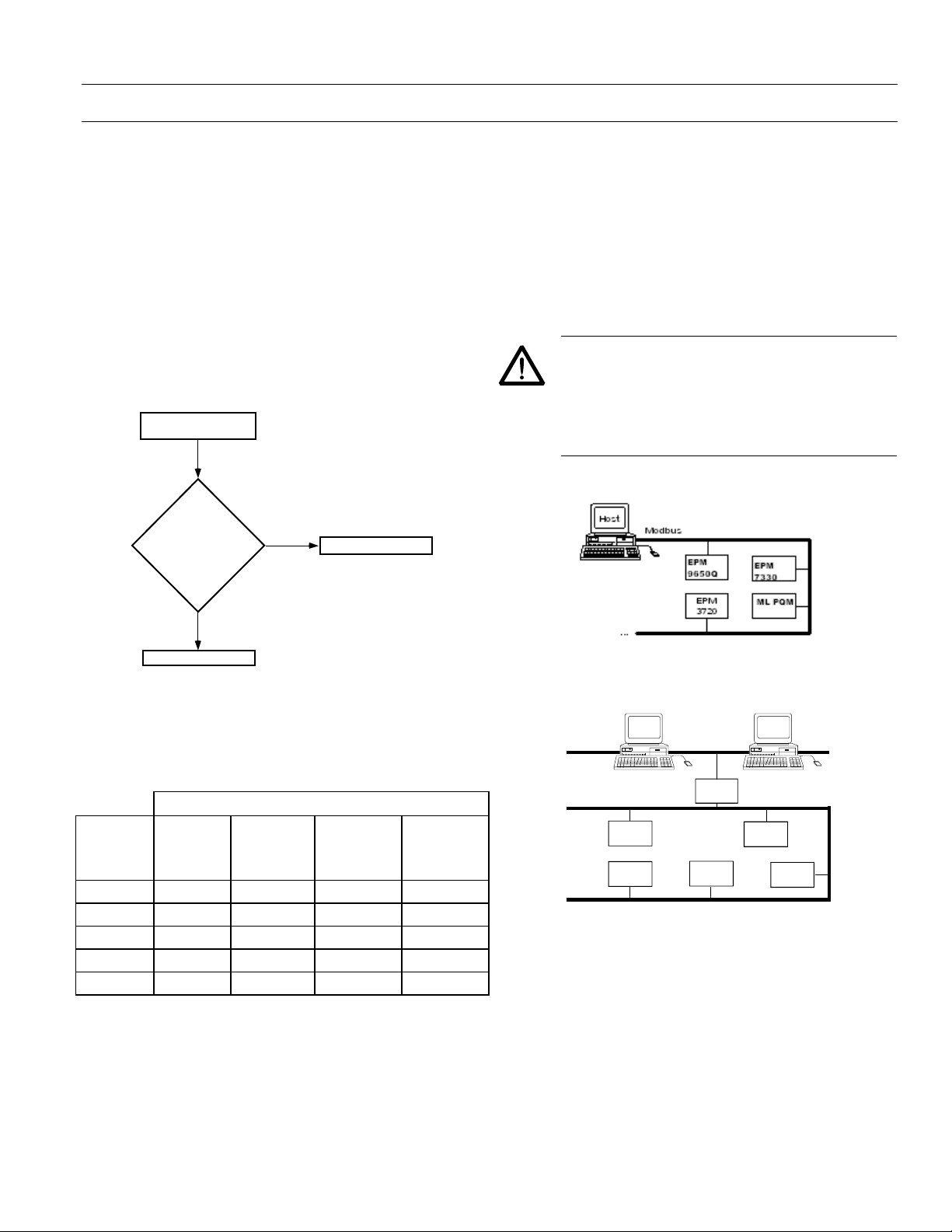
1–1 Typical Systems
The PMCS software is capable of operating on either of
two platforms:
1. PMCS running on a Modbus-based host PC, or
2. PMCS running on an Ethernet-based host PC.
Determine where the PMCS will be based using the
following flowchart:
Should I base my host PC
on Modbus or Ethernet?
Is there an existing
Ethernet or
plans for a
future Ethernet?
No
Base PMCS on Modbus.
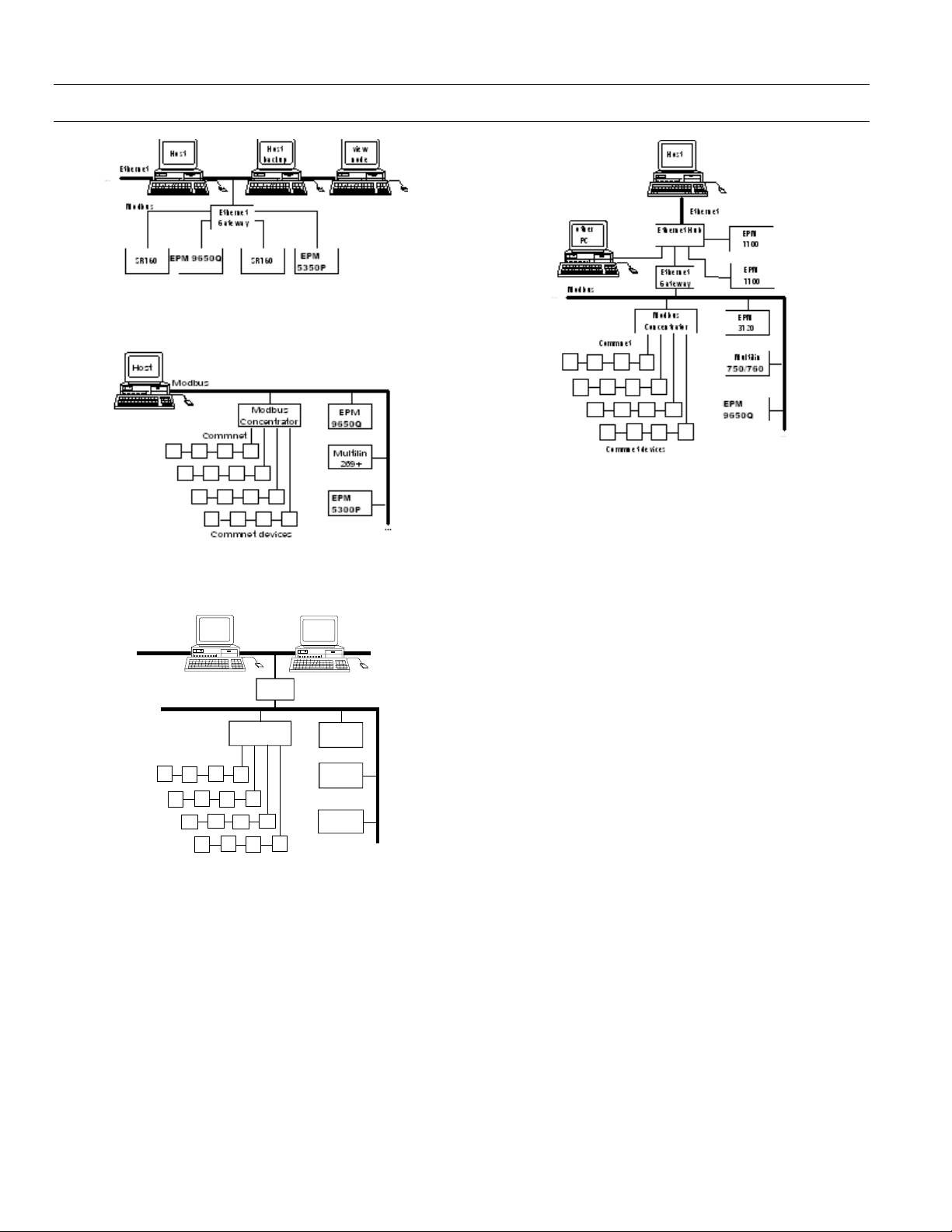
Figure 2 shows a Modbus and Et he rne t network.
Figure 3 shows a Modbus/commnet network.
Figure 4 shows an Ethernet/Modbus/commnet network,
demonstrating the integration of all three protocols.
Figure 5 shows an example of an Ethernet-based host
servicing native Ethernet devices, Modbus devices via the
Ethernet Gateway, and Commnet devices via the Modbus
Concentrator device.
NOTE: Some types of IEDs must be wired on
dedicated private serial network segments, one
IED per serial Modbus line. Figure 2a illustrates
this configuration. The IEDs that require
dedicated Modbus segments are the EPM 9650Q,
EPM 3720, ML PQM, and EPM 7330.
Yes
Base PMCS on Ether net.
After you determine the appropriate base (Ethernet or
Modbus) for the PMCS software, the general network
architecture will fall into one of the forms illustrated in
Figures 1 through 4. These figures offer samples of various
network architecture configurations possible with PMCS.
Protocols Utilized
Ethernet
Direct
Modbus
via
Modbus
Direct
Commnet
Ethernet
Figure 1
Figure 2
Figure 3
Figure 4
Figure 5
üü
üü ü
üü ü ü
ü
üü
As the above table shows, Modbus RTU is required in all
instances, whether it is being used as a stand-alone
network, supporting commnet IEDs, or serving as a slave to
an Ethernet-based host.
Figure 1. Modbus-only network.
EPM
3720
other
PC
M u ltilin
269+
...
...
...
...
Ethernet
Modbus
M ult ilin
565
PLC
90/70
Host
Ethernet
Gateway
PLC
90/30
Figure 2. Commercial Ethernet and Modbus network.
Figure 1 presents the Power Management Control System
operating on a Modbus-only network.
3
Page 14
Power Management Control System
Chapter 1 – Introduction
Figure 2a. Substation Ethernet and Modbus network.
Figure 5. Ethernet-based host services Ethernet, Modbus,
and commnet networks.
Figure 3. Modbus and commnet network.
other
PC
EPM
3720
Mu lt ilin
269+
PLC
90/30
...
...
...
Ethernet
...
Modbus
Host
Commnet
Comm net device s
Ethernet
Gateway
Modbus
Concentrator
Figure 4. Ethernet, Modbus, and commnet network.
1–2 Master-Slave Organization
The PMCS in either a Modbus-host or an Ethernet-host
configuration is a master-slave network. The host is
considered to be the ma ster, with the a ttached n etwor ks of
IEDs serving as its slaves.
This relationship means that the communications are
always initiated a t the host; an IED wil l not speak without
being asked to. The master requests information, the slave
replies.
The PMCS DDE Server receives a request from a client
application for some data, perhaps a relay waveform
capture. The Server routes the request to the correct IED,
the IED replies to the Server, and the Server passes the
information back to the client that originally requested it.
For further details, refer to the PMCS Network and Device
Configurator DDE Server User’s Guide, GEH-6510.
4
Page 15

Power Management Control System
Chapter 1 – Introduction
1–3 Required Hardware
Several pieces of hardware are required to build a network
based on PMCS. They are the host computer and the
network interf ace card, each of whic h is described b elow.
Once the host computer is op era ting a nd its inte rf ace car d
is installed, it is time to attach the power management
IEDs to the network. These IEDs are described in Section
1–8.
Host Computer
The heart of the PMCS is software running on a host PC.
Regardless of whether the host PC is based on an Ethernet
or Modbus network, its functions include the following:
• Communication management
• Primary user interface
• Data collection, storage, and retrieval
• Event reporting with time and date stamp
• Energy calculations and trending
•Network IED status
• Alarming and repo rting
The minimum requirements for the host PC are presented
in GEH-6514, Read This Book Fir s t .
The communications interface is the connection between
the host PC and the network of IEDs. Your host will
require either an Ethernet communications card, an RS485 communications card, or an RS-232/RS-485 converter.
An Ethernet-based host PC requires an Ethernet network
card. A Modbus-based host PC requires an RS-485
interface card or an RS-232/RS-485 converter. These are
described below.
RS-485 Interface Card or RS-232/RS-485 Converter
The RS-485 interface card provides the interface between
the host PC and the Modbus network and ter minates the
network at the host computer. This standard RS-485
interface card provides eight RS-485 ports. PMCS supports
up to 256 RS-485 communication ports. See Sections 2–1,
2–4, and 2–7 for more details on using multiple RS-485
networks with PMCS.
Ethernet Network Card
The Ethernet network card provides the interface between
the host PC and the Ethernet network. With the host
communicating over Ethernet, another interface is
required to communicate with RS-485 networks, where
most power management IEDs reside. (Some recent power
management IEDs, such as the EPM 7700, have built-in
Ethernet capability. Install these devices using standard
Ethernet networking procedures.)
This interface between Ethernet and RS-485 is provided by
the Ethernet Gateway. See Section 1–4 for more
information on Ethernet, and Section 1–1, Figures 2 and
4, for examples of how the Ethernet Gateway is used to
integrate RS-485 networks into the Ethernet network.
1–4 Compatibility & Interconnection with Existing Ethernet Networks
PMCS and the Ethernet Gateway require TCP/IP to be
installed on the host computer. The drivers for the
TCP/IP protocol are included with Windows 2000 SP2,
which is required to run PMCS, so any customer running
PMCS should have these drivers available.
Consult your LAN personnel or system integrator for
information on integrating PMCS with an existing
Ethernet-based netwo rk .
1–5 Operation During Power Outage
PMCS will not lose any data in the event of a power outage;
however, communica tions will be interrupted u ntil power
is restored.
Should control power to a Modbus Concentrator be lost,
PMCS will be unable to c ommunicate with any commnet
IEDs downstream from the Concentrator until power is
restored. No data will be lost, but communications will be
interrupted.
The same is true of the Ethernet Gateway; as the linchpin
connecting the host to the network of IEDs, if a Gateway
loses control power, the host will be unable to
communicate with an y IEDs attached to th e Gateway until
power is restored.
For more modest needs, a single RS-485 network can be
provided by an RS-232/RS-485 converter, a self-contained
IED that converts signals between RS-232 and RS-485. This
IED plugs into the RS-232 port on the back of the host PC
and is less expensive than an RS-485 i nterface card.
You can avoid this situation by providing uninter ruptable
power supplies (UPS) to the host computer and by
providing secure control power to the IEDs, either with
UPS systems or battery backups (different IEDs have
different requirements). Refer to individual user guides
for information on control-power re q u irements.
5
Page 16
Power Management Control System
Chapter 1 – Introduction
1–6 Time & Date Stamping
PMCS stamps each event with a time and date code for
precise reference. The time and date are set by the DDE
Server and passed across the network to each IED, so that
all IEDs are synchronized.
Additionally, some PMCS IEDs support IRIG time
synchronization. If IRIG is used in a PMCS system, it is
recommended that the host PC be IRIG time synched as
well to maintain synchronization between the IEDs and
the PMCS DDE Server.
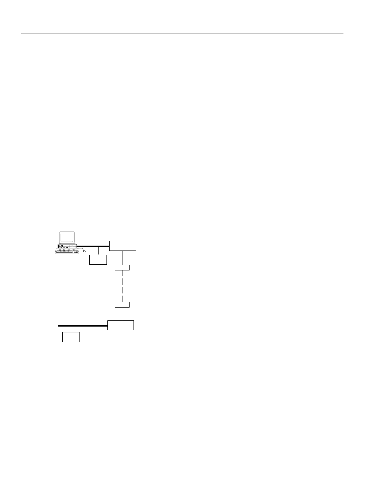
1–7 Remote System Operation
PMCS also offers the ability to use modems to reach across
wide areas to re mote facilities or substation s. For instance ,
you could use PMCS at a central location to collect power
management data from IEDs in a factory, warehouse, or
substation in another state or control the lights, air
conditioning, or protective relays in your facility from
across the country.
An example of this scenario is shown in Figure 5.
Host
...
RS-485 wiring
Radio Frequency transmission,
Fiber optic conn e ct io n,
Leased line
or phone line connection
RS-485 wiring
Modbus
device
Modbus
device
RS-232/RS-485
Converter
RS-232 wiring
Modem
Modem
RS-232 wiring
RS-232/RS-485
Converter
Figure 6. Example of remote operation using modems.
56kbps phone modems, radio frequency (RF) modems,
and fiber optic modems (FOM) may be used with PMCS.
While it is possible to use dial-up lines to connect to distant
RS-485 networks, the vagaries of the phone system and the
excessive long-distance charges preclude using this as a
twenty-four-hour-a-day connection. Leased lines dedicated
to this purpose provide a viable alternative to a constant
long-distanc e telephone connect ion.
For further information on using modems for long-range
operation of PMCS, contact your GE sales representative.
6
Page 17

Power Management Control System
1–8 Supported IEDs
PMCS supports a wide variety of GE and third-party
power management IEDs. These IEDs are listed in
Table 1, along with their function, communications
Chapter 1 – Introduction
protocol, and maximum communications speed for
Modbus-based IEDs (Commnet IEDs must
communicate through the Modbus Concentrator).
IED Name
IED Name
IED NameIED Name
239 Motor Protection Relay Protection/Control Modbus RTU (19.2 Kbaud)
269 Plus Motor Management Relay Protection/Control Modbus RTU (2400 baud)
565 Feeder Management Relay Protection/Control Modbus RTU (9600 baud)
735 Feeder Relay Protection/Control Modbus RTU (19.2 Kbaud)
GE-Zenith Generator PLC (Series 90-70) Metering/Control Modbus RTU (19.2 Kbaud)
GE-Zenith MX200 (Microprocessor Controller) Protection/Control Modbus RTU (19.2 Kbaud)
EPM 7330 Metering Modbus RTU (19.2 Kbaud)
EPM 3710 Meter Metering Modbus RTU (19.2 Kbaud)
EPM 3720 Meter Metering Modbus RTU (19.2 Kbaud)
EPM 7300 Meter Metering Modbus RTU (19.2 Kbaud)
EPM 7700 Meter Metering/Control Modbus RTU (19.2 Kbaud)
EPM 5000P Meter Metering Modbus RTU (9600 baud)
EPM 5200P Meter Metering Modbus RTU (9600 baud)
EPM 5300P Meter Metering Modbus RTU (9600 baud)
EPM 5350P Meter Metering Modbus TCP (Ethernet 10BaseT, RJ-45)
EPM 9450Q Meter Metering/Control Modbus RTU (38.4 Kbaud)
EPM 9650Q Meter Metering/Control Modbus RTU (38.4 Kbaud)
GE Fanuc PLC 90/30 Protection/Control Modbus RTU (19.2 Kbaud)
GE Fanuc PLC 90/70 Protection/Control Modbus RTU (19.2 Kbaud)
GE Fanuc PLC Micro 90 Protection/Control Modbus RTU (19.2 Kbaud)
Universal Relay Protection/Control Modbus RTU (19.2 Kbaud)
MicroVersaTrip-C and -D Trip Units Metering/Protection commnet (requires Modbus Concentrator)
Modbus Concentrator Communications Modbus RTU (19.2 Kbaud)
POWER LEADER Electronic Power Meter Metering Modbus (19.2 Kbaud) or commnet
POWER LEADER Junction Box Communications commnet (requires Modbus Concentrator)
POWER LEADER Repeater Communication commnet (requires Modbus Concentrator)
Power Quality Meter (PQM) Metering Modbus RTU (19. 2 Kbaud on 1 or 2 ports)
Function Communications Protocol (Modbus Speed)
Note: Native Ethernet device.
Modbus TCP (Ethernet 10BaseT, RJ-45)
Modbus TCP (Ethernet 10BaseT, RJ-45)
(commnet requires Modbus Concentrator)
7
Page 18

Power Management Control System
Chapter 1 – Introduction
IED Name
IED Name
IED NameIED Name
RS-485 Repeater Communications Modbus RTU (19.2 Kbaud)
369 Motor Management Relay Metering/Control Modbus RTU (19.2 Kbaud)
EPM 7500 Electronic Power Meter Protection/Control Modbus RTU (19.2 Kbaud)
EPM 7600 Electronic Power Meter Protection/Control Modbus RTU (19.2 Kbaud)
Motor Manager II (MMII) Protection/Control Modbus RTU (19.2 Kbaud)
EPM7430D/EPM7450D (Futura) Protection/Control Modbus RTU ( 9600 baud)
Spectra Electronic Control Module Protection commnet (requires Modbus Concentrator)
Spectra MVT for GEK Frame MCCB Metering/Protection commnet (requires Modbus Concentrator)
SR469 Motor Management Relay Protection/Control Modbus RTU (19.2 Kbaud on 1 or 2 ports)
SR489 Generator Management Relay Protection/Control Modbus RTU (19.2 Kbaud on 1 or 2 ports)
SR745 Transformer Management Relay Protection/Control Modbus RTU (19.2 Kbaud on 1 or 2 ports)
SR750 Feeder Management Relay Protection/Control Modbus RTU (19.2 Kbaud on 1 or 2 ports)
SR760 Feeder Management Relay Protection/Control Modbus RTU (19.2 Kbaud on 1 or 2 ports)
POWER LEADER MDP Overcurrent Relay Protection Modbus (19.2 Kbaud) or commnet
POWER LEADER Modbus Monitor Monitoring Modbus RTU (19.2 Kbaud on 1 or 2 ports)
POWER LEADER Meter Metering commnet (requires Modbus Concentrator)
Table 1. IEDs supported by PMCS.
Function Communications Protocol (Modbus Speed)
(commnet requires Modbus Concentrator)
2
2 The POWER LEADER Ethernet Gateway is not listed in Ta bl e 1. Th e Eth ern et Ga tewa y i s a n a l tern a te h o s t f o r th e RS-485 networks u sed when th e
PMCS resides on the Ethernet level.
8
Page 19

Power Management Control System
Chapter 2 – Network Design
This section describes how to design a Power
Management Control System network on paper so that
actual construction and configuration of the network
will proceed smoothly.
You need two things f or this exercis e: a complete list of
the IEDs to be networked and a diagram or map of
where the IEDs will be located, preferably with realistic
distances noted so that wiring runs may be kept within
the appropriate limits.
Using the list of IED s to be networked , refer to Table 1
and note which communications pr otocols are re quired
(commnet or Modbus). For Modbus IEDs, note the
communications speed at which each IED operates. For
IEDs supporting both p rotocols, you will n eed to decide
which protocol will be used. Generally, it is preferable to
use Modbus rather than commnet unless the Modbus
network is at or near capacity for physical IEDs.
Chapter 2 – Network Design
When the list of IEDs and the floor plan are in hand,
proceed to Section 2–1 for network desi gn rules.
9
Page 20

Power Management Control System
Chapter 2 – Network Design
2–1 Modbus Rules
The most basic network configuration for PMCS assumes
that the software is running on a host PC supporting one
or more RS-485 networks on the Modbus protocol. (See
Figure 1 for an example of this configuration.)
Host PC is
based on:
Modbus 1. The host PC can support
Follow these rules for the
host… And these rules for the attached Modbus network(s)…
Each Modbus network supports up to 31 physical Modbus IEDs
1.
up to 256 independent
Modbus networks. The
actual number is
determined by the
communication cards
installed in the host PC
(see below).
The Modbus networks are
2.
connected to the host PC
via an eight-port RS-485
communications card.
An option for more
limited systems is an RS232/RS-485 converter,
which permits a single RS485 network.
4
3. The host PC must be
located at one end of the
Modbus network(s).
3
and up to 247 Modbus addresses. This is possible because
commnet IEDs attached to Modbus Concentrators occupy
Modbus addresses but do not create an electrical drain on the RS485 network and thus are not counted as physical Modbus IEDs.
Each Modbus network must be properly terminated at each end
2.
of the network. See Section 2–4.
3.
Maximum cable length of e a ch Modbus network is 4000 feet. (S e e
notes on using repeaters to increase this range, Section 2–4. Also,
see the note regarding substation installation in Chapter 3.)
All Modbus IEDs attached to a si ngle RS-485 network must
4.
communicate at the same baud rate. (See Table 1 for Modbus
IEDs’ communication speeds.)
RS-485 cable shields must be properly g ro u nde d . Fo r maximum
5.
protection against surge and EMI damage, each IED on the
network should have an iso l at e d ground connectio n. S e e Section
2–4, Modbus rule 4, for an example of proper RS- 485 wiring and
grounding. Also, see the note regarding substation installation in
Chapter 3.
Table 2 explains the configuration rules for PMCS
networks based on the Modbu s platform. Commnet IEDs
may be integrated through the Modbus Concentr ator ( see
Table 4 for commnet wiring rules).
Table 2. Host PC configuration rules.
3
The following RS-485 interf ace card is recommended for pro viding the RS-485 c onnection at th e host PC. If any o ther serial card i s used, PMCS
requires that the communications driver be compatible with the MS Windows seri al communications proto col. Please refer to Section 3–1 fo r
information on the special termination requirements of the RS-485 card.
Manufacturer Description Quantity/8 ports Part, Order Number
Connect Tech, Inc. Intellicon-Flex8 RS-485 card 1 I4808064XXNC
4
The following RS-232/RS-485 converter is recommended for providing a single RS-485 connection at the host PC.
Manufacturer Description Part, Order Number
Multilin RS-485/RS-232 Converter F485120
When using the above R S - 232/R S - 485 converter, remember that the con verter h a s D IP s wi tc h es inside that determine its ba u d rate. Switch group 3
should be set according to the baud rate at which the converter is to be used. Refer to the converter’s documentation for further information.
Intellicon/DFLEX SLIM 4 SIMMS
8 Port, DB9 I/O Box 1 IOB08DB9
10
Page 21

2–2 Ethernet Configuration Rules
Power Management Control System
Chapter 2 – Network Design
It is also possible to run the PMCS on a host PC operating
on an Ethernet network. If PMCS is running on an
Ethernet-based PC, an Ethernet Gateway is required to
communicate with the attac hed Modbus networ k(s). (See
Figure 2 for an example of this configuration.)
Recently, IEDs with built-in Ethernet support have begun
to become available; PMCS is also capable of supporting
these devices. Examples of such devices are the EPM 7700
meter and EPM 9450Q / 9650Q meters. These devices
reside on the Ethernet network at the same level as the
Ethernet Gateway.
Table 3 explains the configuration rules for PMCS
networks based on the Ethernet platform. Commnet IEDs
may be integrated through the Modbus Concentrator.
(See Table 4 for commnet wiring rules.)
EPM 7700 devices require a separate network
configuration beyond connecting the devices to the
Ethernet LAN. Please refer to the following PMCS
technical documentation for complete network
configuration rules and guidelines:
GEH-6514, PMCS Read-This-Book -First. Refer to the section
titled “Configuring the EPM 7700 De vice Network.”
DEH-40035, GE 7700 Gateway User’s Guide. Refer to the
section tit l e d “EPM 7700 Network Config uration.”
EPM9450Q and EPM9650Q devices require separate
network configuration beyond connecting the devices to
the Ethernet LAN. Refer to the instruction manuals of
these devices a nd to the sections titled “Inter nal Network
Option.” Also refer to DEH-6510, DDE Server User’s Guide.
Refer to the sections describing the use and configuration
of the Modbus TCP Server.
11
Page 22

Power Management Control System
Chapter 2 – Network Design
Host PC is
based on: Follow these rules for the host…
Ethernet 1. Ethernet Gateway(s) must be used to
communicate with non-Ethernet IEDs.
Ethernet-capable IEDs may be installed
directly on the Ethernet network at t he
same level as the Ethernet Gateway(s).
The host PC supports up to 64 Ethernet
2.
Gateways.
3.
Each Ethernet Gateway supports up to
four independent Modbus networks.
The EPM 9450Q /9650Q devices wi ll
support one Modbus network.
The actual number of IEDs supported
4.
by the host varies from system t o system,
depending on the variety of IEDs used
and the number of PMCS data tags
required by the IEDs. See GEH-6509,
PMCS DDE Interface Guide, for details.
Ethernet networks should conform to
5.
the design guidelines described in
Section 2-3.
Table 3. Ethernet configuration rules2–3 Ethernet Network Considerations
And these rules for the Modbus networks attached to the
Ethernet Gateways…
Each Modbus network supports up to 31 physic al
1.
Modbus IEDs and up to 247 Modbus addresses. This
is possible because commnet IEDs attached to
Modbus Concentrators occupy Modbus addresses
but are not seen as physical Modbus IEDs.
Each Modbus network must be properly terminated
2.
at each end of the network. See Section 2–4.
3.
The Ethernet Gateway must be located at one end of
the Modbus network(s).
4.
Maximum cable length of each Modbus network is
4000 feet. (See notes o n using repeaters to increa se
this range, Section 2–4. Also, see the note regarding
substation installation in Chapter 3.)
All Modbus IEDs attached to a single RS-485
5.
network must communicate at the same baud rate.
(See Table 1 for Modbus IEDs’ communication
speeds.)
RS-485 cable shields must be properly gro u nd ed . Fo r
6.
maximum protection against surge and EMI
damage, each IED on the network should have an
isolated grou nd c onnection. See S e c tion 2–4,
Modbus rule 4, for an example of proper RS-485
wiring and grounding. Also, see the no te regarding
substation installation in Chapter 3.
This section describes some of the specifications which
must be considered when designing an Ethernet network
to be used with PMCS.
Note: These specifications are guidelines only and should
not be used for actual network design. Consult with a
qualified LAN engineer for design requirements that meet
your specific installation. The complete specifications are
listed in IEEE 802.3 Ethernet. In addition, the National
Electrical Code (NEC) and all applicable local codes must
be followed for installing wiring.
Ethernet supports four physical media: 10Base-2
(thinnet), 10Base-5 (thicknet), 10Base-T (twisted pair),
and 10Base-FL (fiber). 10Base-T is most common.
12
Page 23

Power Management Control System
Chapter 2 – Network Design
NOTE for EPM 7700 and 9450Q and 9650Q: The EPM
7700 with Xpress card directly uses either of two types of
Ethernet physical media that must be specified when
ordering the meter, 10Base-T, or 10Base-FL. EPM 9450Q
and EPM 9650Q must be ordered with 10 Base-T Ethernet
Option. The meters operate in a 10 Mbps system.
10Base-T is specified when twisted pair is used and 10BaseFL is specified where fiber optic cable is used. While media
converters are available to allow the use of both twisted
pair and fiber optic cable in the same LAN, and can be
used to extend the length of the LAN, th ey ar e bey ond the
scope of this discussion.
CAUTION: The recommended installation
practice is to implement optical fiber for
connections between buildings to provide
electrical isolation. This eliminates harmful
ground loops caused by differences in the
ground potenti a l be tween structures.
CAUTION: Data line surge protection is
recommended for network components such as
hubs, computers, or modems connected to IEDs
with copper wire, especially installations where
the data communication cable is exposed (i.e.,
not encased in conduit) or runs parallel to power
conductors. PMCS IED s ar e r outinel y in stal led in
areas exposed to heavy electromagnetic fields
(EMF), which can induce damaging surges in
data communication lines. Data line surge
protection is not required for fiber optic
connections.
A 10Base-T LAN can have a maximum of 1024 devices
connected.
Use of repeaters, routers, bridges, gateways, etc.
Repeaters may be used to connect LAN segments and do
not determine the boundaries of the LAN. They are used
to extend the LAN beyond a single segment. Routers,
bridges and gate ways may be used to conn ect the LAN to
other LANs or to a WAN.
10Base-FL specifications and rules
Maximum/Minimum length of segments
For a 10Base-FL LAN, the maximum length of a segment is
2000 meters (6500 ft). The minimum length of any cable
is 2.5 Meters or about 8 ft. This minimum length is of
particular concern when a device is located in close
proximity to the hub.
Maximum number of segments
A 10Base-FL LAN ca n consist of up to 5 s egments using 4
repeaters. However, only three of these segments can have
devices connected.
Maximum number of devices
A 10Base-FL LAN can have a maximum of 1024 devices
connected.
Use of repeaters, routers, bridges, gateways, etc.
Repeaters may be used to connect segments and do not
determine the boundaries of the LAN. They are used to
extend the LAN beyond a single segment. Routers, bridges
and gateways may be used to connect the LAN to other
LANs or to a WAN.
10Base-T specifications and rules
10Base-T Ethernet uses CAT 3, 4 or 5 twisted pair cable,
depending on the installation.
Maximum/Minimum length of segments
For a 10Base-T LAN, the maximum length of a segment is
100 meters (328 ft). The minimum length of any cable is
2.5 Meters or about 8 ft. This minimum length is of
particular concern when a device is located in close
proximity to the hub.
Maximum number of segments
A 10Base-T LAN can consist of up to 5 segments using 4
repeaters. However, only three of these segments can have
devices connected.
Maximum number of devices
13
Page 24

Power Management Control System
Chapter 2 – Network Design
2–4 Commnet Configuration Rules
POWER LEADER commnet IEDs may be integrated into a
PMCS network through a special Modbus IED called the
Modbus Concentrator. The rules outlined in Table 4 apply
to using commnet IEDs with PMCS, regardl ess of whether
the host PC is operating on an Ethernet or Modbus
network. (See Figures 3 and 4 for examples of commnet
IEDs operating on PMCS.)
Rules
regarding: Commnet IED configuration rules:
Modbus
Concentrator
limitations
Commnet
wiring
limitations
1. Each Modbus Concentrator supports up to eight commnet segments.
2.
Each commnet segment supports up to four commnet IEDs.
3.
Only one waveform-capturing meter (POWER LEADER Meter) is allowed per
commnet segment.
4.
POWER LEADER Repeaters and Junction/Outlet Boxes do not count toward the
four-IED-per-segment limit.
5.
No connections between commnet segments are permitted. Each segment must
be wired independently (having no contact with other commnet segments) and
connected to the Concentrator at one point only (no loops permitted).
1. Maximum cable length o f a commnet segment is 1000 fe e t. Maximum range
between commnet IEDs o n a se g ment is 1000 feet (except for repeaters; see
below).
In no case may a commnet IED be wired more than 1000 feet fro m the Modbus
2.
Concentrator or a POWER LEADER Repeater.
3.
POWER LEADER Repeaters may be used to extend the range of commnet
segments. A repeater regenerates t he co m m net signal to its origi nal st reng th,
allowing it to t ravel up to another 1000 feet.
Long-distance segments may be created by placing multiple repeaters adjacent to
4.
one another in a commnet segment. A repeater communicating directly with
another repeater may span up to 6000 fe e t .
Maximum allowable cable length of a si ngle commnet segment i s 12,000 fe et,
5.
which may be constructed with any allowable combination of repeaters and IEDs.
6.
For ease and economy of wiring, the POWER LEADER Junction/Outlet box may
be used to create nodes of commnet IEDs with a common wiring point to be
connected to the Modbus concentrator. The POWER LEADER Junction/Outlet
Box allows the interconnection of as many as four shielded, twisted-pair cables to
create this common wiring point. For instance, rather than a daisy-chain of
wiring in a lineup from one meter or trip unit to the next, up to four IEDs may be
wired to the POWER LEADER Junction/Outlet Box, which is then connected to
the Modbus Concentrator.
Reference
Figure:
Figure 15
Figure 15
No figure
provided
Figure 19 and
Figure 20
Figure 28 –
Figure 32
Figure 16
Figure 16
Figure 17
Figure 18
No figure
provided
Figure 19 and
Figure 20
Table 4. Commnet IED configuration rules.
14
Page 25

Power Management Control System
Chapter 2 – Network Design
2–5 Modbus Wiring Rules – Diagrams
The Modbus network protocol ha s wiring rules and limits
on the number of IEDs that may be attached.
This section describes in greater detail the rules you must
follow when designing a Modbus network.
WARNING: Network wiring and grounding
rules described herein apply primarily to
commercial/industrial installations. Substation
installations will exist in the presence of
dangerously elevated ground potential relative to
points outside of th e station grid as we ll as large
electromagnetic induction fields. Additionally,
large ground faults can elevate substation
ground potentials. Follow local utility bestpractices/safety procedures to prevent risk of
shock/electrocution to personnel and damage to
equipment that could result in a loss of
protection and communications.
NOTE: It is important to take future
expandability into c ons ider ation wh en des ignin g
a network configuration. This is particularly so
when the network is near its maximum n umber
of IEDs or maximum cable length. Adding IEDs
to a network after it has been installed may
require rewiring the network.
1. Each RS-485 network may support up to 31 Modbus
IEDs. Figure 7 illustrates this rule. (See the
exception below Figure 6.)
Host
31 RS-485 IEDs maximum;
PMCS Ho s t PC, Ethernet G ateway or MSP
always located at one en d of Modbus network.
Figure 7. Network illustrating Modbus Rules 1 and 2.
Exception to Rule 1: Some types of IEDs must be
wired on dedicated private serial network segments,
one IED per serial Modbus li ne .
2. The host (or Ethernet Gateway) must always be
located at one end of any Modbus segment. It may
not be located in the center of a M odbus network.
Figure 7 shows the correct placement of the host
(PC or Ethernet Gateway).
3. All Modbus IEDs on a single RS-485 network must
communicate at the same baud rate. If IEDs with
different communication speeds are connected to
the same RS-485 network, the whole segment will
communicate at the speed of the slowest IED. Figure
8 illustrates this rule. (Communication speeds for
supported IEDs are listed in Table 1.)
CAUTION: Wire-run distances mentioned in the
configuration rules assume application above
grade or in conduit. For below-grade
applications, refer to Section 3–1, Wiring
Requirements.
Regardless of which platform is supporting the RS-485
networks (Ethernet Gateway, RS-485 card, or RS-232/RS485 converter), the following rules apply to each
individual RS-485 network.
Figure 8. Network illustrating Modbus Rule 3.
4. Each RS-485 network must be properly terminated
at both ends of the cable run after the final IED.
(See Section 3–1 f or details on te rmination.) F igure
9 illustrates this rule.
15
Page 26

Power Management Control System
Chapter 2 – Network Design
5. Each RS-485 network must have its shield properly
grounded. Figure 9 illustrates proper RS-485 wiring
and grounding.
CAUTION: Improper grounding may create a
ground-loop condition and cause
communications failures. Make sure you follow
the wiring diag ram carefully.
To ensure proper grounding, follow this procedure.
Begin by grounding the RS-485 cable shield at the
host. Follow the cable to the first IED on the
network. Do NOT conn ect the cable ground to the
IED. Pick up the RS-485 output cable from the IED
and attach its groun d to th e I E D’s shield con n e c tion
or grounding screw. For IEDs with no grounding
connectors, connect to earth ground.
Follow the cable to the next IED, and repeat the
above procedure. Do not connect the RS-485 shield
from the previous IED, but DO connect the RS-485
OUT shield on its way to the next IED.
EXCEPTION: The Multilin 565 Feeder
Management Relay does not have isolated
communications ports. Do NOT connect the
shield at this IED. Instead connect the shield of
the incoming RS-485 cable to the shield of the
outgoing RS- 485 c a ble , sk ipping the Multili n 565.
Two wir e, twis ted,
shielded pair cable
RS-485 IED #1
Shield
RS - 485 IED # 2
Shield
RS-485 Host
RS-485
+
-
+
-
(RS-485 c a rd* , RS232/RS-485 converter ,
Multiple Serial P o rt o r Ethernet Gateway RS -485 port)
Network Connections: + - Shield
Shield
connected
at host
120-ohm terminating resistor
* Con ne ct Tech RS-485 cards
require a 600-ohm resistor
in place of the 120-ohm
terminatin g res istor.
Sh ield no t
connected
at first IED
RS-485 IN
Shield
connected
at first IED
RS-485 OUT
Sh ield no t
connected
at IED
RS-485 IN
Shield
connected
at IED
RS-485 OUT
Rules of thumb: RS-485 cable ground should always be
connected at the previous IED, never upon arrival at
an IED. All RS-485 IEDs must have either two
communications cables attached or one
communications cable and a terminating resistor.
Shield not
RS-485 IED #31
Shield
120-ohm
terminating resistor
+
-
connected
at IED
RS-485 IN
Figure 9. Network illustrating Modbus Rules 4 and 5.
6. A single RS-485 network may have up to 215
commnet IEDs attach ed to it via POWER LEADER
Modbus Concentrators. Figure 10 illustrates this
rule.
16
Page 27

Power Management Control System
Chapter 2 – Network Design
Host
RS-485 IEDs
(31 Max)
MC
Modbus
Concentrator
Commnet IEDs
(up to 32 per Modbus Concentrator,
215 tota l per RS-485 network)
Figure 10. Network illustrating Modbus Rule 6.
7. A single RS-485 network may have no more than
4000 feet of cable (total cable length, not distance
between IEDs). Figure 11 illustrates this rule.
RS-485 IEDs
Host
100 ft
Total Cable Length < 4000 feet
200 ft 300 ft
(31 M ax)
1500 ft
9. There may be no more than two RS-485 repeaters
between any two RS-485 IEDs. Figure 13 illustrates
this rule.
Rptr Rptr
Correct - Maximum two repeaters between RS-485 IEDs
Rptr Rptr Rptr
Incorrect - more than 2 repeaters between RS-485 IEDs
Figure 13. Network illustrating Modbus Rule 9.
NOTE ON DUAL-PORT RS-485 IEDS:
Several of th e Mul tilin pow er man agement I EDs
offer two RS-485 ports on the same IED. Do not
connect both RS-485 ports to a PMCS network. The
same data are available from both RS-485 ports
and will cause conf licts if the PMCS attempts to
access both ports simultaneously.
However, the Modbus Mo nitor’s wiring sche m e is
slightly differe nt from the Multilin sch eme. The
dual-port version of the POWER LEADER
Modbus Monitor MUST be connected to two
separate RS-485 networks. S ee Rule 10 fo r d e tails.
300 ft
1500 ft
Figure 11. Network illustrating Modbus Rule 7.
8. RS-485 repeaters may be used to extend the range
beyond 4000 feet. A single RS-485 repeater may be
used to provide a 4000-foot extension, and each
additional repeater in a sequence extends the range
by another 4000 feet. Figure 12 illustrates this rule.
Host
100 ft
With 2 Repeaters,
Total Cable Length < 8000 feet
200 ft
500 ft 700 ft
4000 ft
2500 ft
R
R
RS-485
Repeaters
Figure 12. Network illustrating Modbus Rule 8.
10. Modbus Monitors (dual-port version) may not be
wired in any configuration other than the four
shown in Figure 14 . Although the Monitor’ s RS-485
ports have separate addresses, you may NOT wire
the same Modbus n etwork to both por ts. A two-port
Modbus Monitor must be wired to two separate
Modbus networks .
NOTE: For more information on wiring the
POWER LEADER Modbus Monitor, refer to
DEH-027, Modbus Monitor User’s Guide.
17
Page 28

Power Management Control System
Chapter 2 – Network Design
Modbus
Segment A
Modbus
Segment A
Example B
Modbus
Segment B
Monitor
#1
Example D
Modbus
Segment B
Monitor
#1
Monitor
#2
Example A
Modbus
Segment A
Monitor
#1
Example C
Modbus
Segment A
Monitor
#1
Monitor
#2
Figure 14. Valid Modbus Monitor network architectures.
CAUTION: Any other wiring of the Modbus
Monitor may result in incorrect operation and
errors.
makes this concern irrelevant for examples A, B,
and D, since in Example A you could have either
a single- or a dual-port Monitor, while in
Examples B and D you may only use a dual-port
monitor(s).
CAUTION DUAL PORT MONITO R USERS: Do
not connect the Monitor’s two RS-485 ports to the same
Modbus segment. This will cause communication
errors and possibly damag e the Monitor.
Example A shows a single Modbus Monitor wired to one
Modbus segment. Example B shows the same monitor in a
dual-port version, wired to two different Modbus segments.
Examples C and D illustrate fully loaded Modbus
segments. No more than two Monitors are permitted on
any Modbus segment.
Example C illustrates a pair of Monitors connected to a
single Modbus segment. In this example, the Monitors
may be either single port or dual-port versions, provided
both are the same version (see note below). Example D
shows the same pair of Monitors wired to a second Modbus
segment.
CAUTION: With regard to Example C (two
Monitors on a single RS-485 segment), it is not
permissible to mix different models of Monitors
on a segment. Monitors #1 and #2 must be of the
same model, either both sin gle-p ort or both d ualport.
The nature of the other network architectures
18
Page 29

Power Management Control System
g
g
)
Chapter 2 – Network Design
2–6 Commnet Wiring Rules – Diagrams
POWER LEADER commnet IE Ds may be integrated into
PMCS through the us e of the POWER LEADER M odbus
Concentrator, which collects data from commnet IEDs
and communicates that data across the RS-485 network.
Each Modbus Concentrator supports up to eight commnet
segments. Each commnet segment may accommodate up
to four commnet IEDs. The following are the basic rules to
ensure proper network operation for POWER LEADER
commnet IEDs. Note that these rules apply only to
individual commnet segments of a POWER LEADER
Modbus Concentrator, no t to the RS-485 network.
1. Each Modbus Concentrator supports up to eight
commnet segments. Each commnet segment may
support up to four commnet IEDs, only one of
which may be a waveform-capturing meter. POWER
LEADER Repeaters and Junction/Outlet Box es are
not counted as commn et IEDs. Figure 15 ill ustrates
this rule.
Modbus
Concentrator
4 co mm net IEDs/seg me nt
max
degrades and the danger of errors rises to an
unacceptable level. The Repeater regenerates a
signal to its origina l stre ngth, a llowin g it to trav el up
to another 1000 feet. Thus, each Repeater can add
up to 1000 feet of range t o the commnet segment.
For example, a segment containing a single
Repeater may have no more than 2000 feet of total
cable length. No more than 1000 feet of cable are
permitted between the Modbus Concentrator and
the first Repeater or between the Repeater and the
last IED on the segment. Figure 17 illustrates this
rule.
CAUTION: In no case may there be more than
1000 feet of cable between any two commnet
IEDs other than Repeaters. At ranges over 1000
feet, commnet signals become degraded and
communication errors may result.
Modbus
Concentrator
400 ft
R
200
600
ft
ft
Max length of a commnet segment
with one Repeater < 2000 feet
600
200
ft
ft
Figure 15. Network illustrating commnet Rule 1.
2. A commnet segment may have no more than 1000
feet of cable between the Modbus Concentrator and
the final IED on a segme nt. (Re peater s ma y be used
to extend this range; see Rule 3.) Figure 16
illustrates this rule.
Modbus
Concentrator
300 ft
200
200
ft
th of a co mm net segment < 1000 feet
Max len
200
ft
ft
Figure 16. Network illustrating commnet Rule 2.
3. The maximum communication range of commnet
IEDs (including the Modbus Concentrator’s
commnet ports) is 1000 feet, after which its signal
Figure 17. Network illustrating commnet Rule 3.
4. Long-distance cable runs may be built by placing two
Repeaters adjacent to one another in the segment. A
pair of adjacent Repeaters has a range of up to 6000
feet of cable. Figu re 18 illustrates this rul e .
Modbus
Concentrator
400 ft
R R
6000
1000 ft
RR
6000
ft
Max length of a commnet segment
with three Repeaters < 12000 feet
(note: only one other IED may be used o n
a commnet se
600
ft
ft
Max length of a commnet segment
with two Repeaters < 8000 feet
4000
ft
men t w ith three repeaters
600
R
ft
200ft200
1000
ft
ft
Figure 18. Network illustrating commnet Rule 4.
5. The maximum allowable cable length of a single
commnet segment is 12,000 feet. This may be
19
Page 30

Power Management Control System
Chapter 2 – Network Design
achieved with any allowable combination of
Repeaters and IEDs.
6. For ease of wiring, the POWER LEADER
Junction/Outlet Box may be used to c reate node s of
commnet IEDs with a common wiring point to be
connected to the Modbus concentrator. The
POWER LEADER Junction/Outlet Box allows the
interconnection of as many as f our sh ielde d, tw isted pair cables to c rea te this common wir ing poin t. T his
can be of great help in economizing on wiring and
offering greater flexibility in network design. For
instance, rather than a daisy-chain of the wiring in a
lineup from one meter or tr ip u nit to the n ext, u p to
four IEDs may be wired to the POWER LEADER
Junction Box, which is then connected to the
Modbus Concentrator.
CAUTION: The four-IED-per-segment limit must
be observed at all times. Although the POWER
LEADER Junction Box has terminals to accept
up to 12 commnet lines, do NOT connect more
than four commnet IEDs to a single Junction
Box or Modbus Concentrator commnet segment.
Examples of the use of a POWER LEADER Junction
Box with the Modbus Concentrator are provided in
Figure 19 and Figure 20. Junction Boxes are not
counted as IEDs for purposes of the four IED per
commnet segment limit. Figure 19 is an example of
a Junction Box used to create a node connecting
four commnet IEDs to a Modbus Concentrator.
Figure 20 is an example of a Junction Box with
Repeaters, observing the four IED per segment limit
(the two Repeaters and the Junction Box do not
count as IEDs).
commnet
IED
to
Modbus
Concentrator
comm n e t
IED
Junction
Box
comm n e t
IED
comm n e t
IED
Figure 19. Network illustrating commnet Rule 6.
commnet
to
Modbus
Concentrator
comm n e t
IED
IED
Junction
Box
commnet
IED
Long-range
comm net segment
POWER
LEADER
Repeater
POWER
LEADER
Repeater
comm n et
IED
Figure 20. Network illustrating commnet Rule 6.
20
Page 31

Power Management Control System
Chapter 2 – Network Design
2–7 Performance Recommendations
Although a PMCS network will function as long as all the
rules in the previous section are followed, you can enhance
performance by considering the following
recommendations for Modbus, commnet.
The Ideal Network
Theoretically, a single Modbus IED or 40 commnet IEDs
distributed across five Modbus Concentrators (one IED
per commnet segment) yields maximum performance.
Naturally, in the r eal world few ne tworks will fall into th is
precise configuration. To extract maximum performance
from the PMCS, follow the performance recommendat ions
below.
Modbus performance recommendations
Use multiple RS-485 networks if possible, depending
1.
on the RS-485 connection at the host. If using an
eight-port RS-485 card or an Ethernet Gateway (four
ports) for connection to the network, you can improve
performance by using the full number of ports
available, rather than burdening a single RS-485 port.
Distributing the IEDs across all available RS-485 ports
permits the communications load to be distributed
rather than asking a single network to carry the full
load.
Divide the IED loads evenly when distributing IEDs
2.
across multiple RS-485 networks.
Pay careful attention to Modbus Rule 2, regarding the
3.
communication speeds of IEDs on a given network.
Although a network w ill function with mixed IE Ds, its
communication speed will be dragged down to the
lowest common denominator. Thus, a single 2400baud IED forces the e ntir e ne twor k to commun icate a t
2400 baud, regardless of the presence of any 19.2kbaud IEDs.
Commnet performance recommendations
Modbus is preferred over commnet where either
1.
protocol is available. This is the case for the POWER
LEADER Electronic Power Meter and the POWER
LEADER MDP Overcurrent Relay. Each of these IEDs
offers a Modbus communications option.
Minimize the number of commnet IEDs per segment.
2.
The Modbus Concentrator is a polling IED, meaning
that it queries each commnet segment continuously
and in order asking for information. It then stores the
information until it is asked b y the PMCS to transmit
its data to the host. If the n umber of c ommnet IEDs is
unevenly distributed, the Concentrator takes longer
than necessary to poll each segment.
3. Keep data-intensity in mind when connecting more
than eight commnet IEDs to a single Modbus
Concentrator. If it is necessary to connect more than
eight commnet IEDs to a single Modbus Concentrator,
one or more segments will be supporting multiple
IEDs. Keep the following list in mind when selecting
which IEDs to double up on the same commnet
segment. The best choices for doubling up are listed
first.
Spectra MicroVersaTrip trip unit
1.
2. Enhanced MicroVersaTrip-C and -D trip units
3. POWER LEADER MDP Overcu rre nt Relay
4. Spectra Electronic Control Module
5. POWER LEADER Electronic Power Meter
6. POWER LEADER Meter
IEDs at the top of the list are less data-intensive and
easier for the Concentr ator to p oll. IE Ds at th e bottom
of the list are very data-intensive and, if possible,
should be given their own commnet segment. In other
words, if you must put multiple IEDs on a segment, it is
preferable to put low-demand IEDs together on a
segment and try to keep high-demand IEDs on their
own segments. Try to distribute the high-demand
IEDs across the available segments, keeping the
number of high-demand IEDs per segment evenly
distributed.
2–8 Addressing the IEDs
Each IED attached to a PM CS network must have a u n iq u e
address. Prior to installing any wiring, you should plan the
addresses for the IEDs to avoid any conflicts. Keep in mind
these important points when assigning network addresses.
• Keep a table of IED names and addresses to avoid
conflicts and to help with host configuration. Table 5
summarizes Modbus addressing considerations,
based on the following rules.
- Modbus Concentrator addresses must be in the
range of 1 to 32.
- Modbus-native IEDs other than the Concentrator
may occupy any address from 1 to 247.
- Commnet IEDs must have Modbus-equivalent
addresses in the range of 33 to 247.
- The host PC does not require an address due to the
master-slave organization of the PMCS.
21
Page 32

Power Management Control System
Chapter 2 – Network Design
NOTE: Per the EIA485 standard, each RS-485
network supports up to 32 “drops” or electrical
drains on the network. However, the Ethernet
Gateway or RS-485 interface card counts as one
drop. Thus, only 31 other IE Ds may be attached
to each RS-485 network, even though 32 Modbus
addresses are available for use. Also, unlike
commnet’s POWER LEADER Repeaters, RS-485
repeaters are counted as IEDs because although
they have no Modbus address, they do act as a
drop on the network.
Modbus
Address
0 • Broadcast (not available to user)
1 – 32 • Modbus Concentrators must have addresses
33 – 247 • Modbus native IEDs may have addresses in
Table 5. Modbus address range appropriate usage.
• Commnet IEDs are preprogrammed with a factory-set
address. You must change this address immediately
upon installation of the I ED. Refer to the IE D’s user
manual for instructions on assi g ni ng an address.
• Because the commnet network accepts a different
range of addresses than the Modbus network,
commnet addresses must be mapped to
corresponding Modbus addresses. The formula for
Appropriate Usage/Supported IEDs
in this range
• Other Modbus native IEDs may also have
addresses in this range
this range
• Commnet IEDs must have addresses in this
range
this mapping is: desired Mod b u s a d dress + 267 = commnet
address to set at IED. For example, to set a commnet
IED to Modbus address 33, the commnet address set
at the IED must be 300. Table 6 illustrates address
mapping.
For Modbus Address: Set commnet IED Address to:
33 300
34 301
35 302
... ...
246 513
247 514
Table 6. Modbus-to-commnet address mapping.
- You may wan t to block commnet address assignmen ts
by lineup and/or Modbus Concentrator segment. For
example, start with 40 for the first l ineup attache d to
one Modbus Concentrator, 50 for the second lineup
attached, and so on. Addresses must be in the range
33 to 247. The example presented in Figure 18
demonstrates this.
- Increment the individual IEDs in each lineup by one.
For example, if the first IED in a lineup is Modbus
address 101, the second IED should be 102, the third
IED should be 103, etc.
• Addresses may be entered or changed at any time
that control po we r is present.
Figure 21 illustrates a sample network with IED addresses;
Table 7 provides details of the IEDs shown in Figure 21.
22
Page 33

Power Management Control System
Chapter 2 – Network Design
Figure 21. Sample network with IED addresses.
23
Page 34

Power Management Control System
Chapter 2 – Network Design
Equipment
Lineup 1
POWER/VAC Medium-Voltage
Switchgear
Lineup 2
8000-Line Motor Control Center
Lineup 3
AKD-8 Low-Voltage Switchgear
Lineup 4
Medium-Voltage Motor Control Center
Lineup 5
Substation
Attached
IEDs
Modbus Concentrator 1
Segment 1
POWER LEADER Electronic Power Meter
MDP Overcurrent Relay with commnet
MDP Overcurrent Relay with commnet
MDP Overcurrent Relay with commnet
Segment 2
POWER LEADER Electronic Power Meter
POWER LEADER Electronic Power Meter
Segment 3
POWER LEADER Electronic Power Meter
POWER LEADER Electronic Power Meter
Segment 4
MDP Overcurrent Relay with commnet
MDP Overcurrent Relay with commnet
EPM 7700 Electronic Power Meter
Multilin 269 Plus Motor Relay
Modbus Concentrator 2
Segment 1 - Spectra Electronic Control Module
Segment 2 - Spectra Electronic Control Module
Segment 3 - Spectra Electronic Control Module
Segment 4 - Spectra Electronic Control Module
EPM 7700 Electronic Power Meter using IP address =
3.46.9.102
Modbus Concentrator 3
Segment 1 - POWER LEADER Meter
Segment 2 - Enhanced MicroVersaTrip trip unit
Segment 3 - POWER LEADER Meter
Segment 4 - Enhanced MicroVersaTrip trip unit
GE Fanuc Programmable Logic Controller 90/30
Multilin 565 Feeder Management Relay
EPM 5300P
EPM 5200P
EPM 9650Q
EPM 7300
EPM 7330
EPM 7330
Modbus
Address
001
035
036
037
038
040
041
045
046
050
051
052
060
002
065
070
085
090
n/a
003
155
160
165
170
175
180
185
004
005
200
205
210
215
220
225
Commnet
Address
—
302
303
304
305
307
308
312
313
317
318
—
—
—
332
337
352
357
n/a
—
422
427
432
437
442
447
452
—
—
—
—
—
—
—
—
Table 7. IED-addressing scheme for Figure 21.
24
Page 35

Power Management Control System
Chapter 2 – Network Design
2–9 Multiple RS-485 Networks – Addressing
PMCS supports up to 256 inde pe nd e nt Modbus networks.
Regardless of how many RS-485 networks are connected,
the addressing concepts regarding multiple RS-485
networks remain the same. Each RS-485 network is
addressed independently of the others. Thus, Network 1
may have an IED with Modbus address 20, and Network 2
may have an IE D with Modbus ad d r e s s 20 without c on f l ic t.
The PMCS will be aware that they are different IEDs,
much as the postal system delivering mail realizes that 17
Mulberry Lane in Town A is a different address than 17
Mulberry Lane in Town B.
2–10 System Expansion
Whenever new IEDs are added to the network, be sure to
observe these points:
• Follow the proper installation procedures.
• Ensure that the system configuration rules have been
followed.
• All new IEDs are shipped with the same default
address. To avoid conflicts, change the address of
each new IED immediately upon installation to an
unoccupied address in the PMCS networks.
2–11 Case Studies
Five case studies are provided as examples of how to design
a network based on PMCS. In each case, a fictitious
company called GHO Corp. is installing a power
management system based on PMCS.
In Case One, GHO Corp. has only a few Modbus RTUbased IEDs that it would like to network to the PMCS
software for remote control and viewing of power
consumption and alarms.
In Case Two, GHO Corp. wishes to expand the Modbus
network it developed in Case One by adding some
commnet IEDs to the network.
In Case Three, GHO Corp. already has an existing
network based on Ethernet and would now like to
integrate a power management system with this network.
GHO Corp. still has only a few Modbus RTU-based IEDs
that it would like to network to the PMCS for remote
control and viewing of power consumption and alarms.
Now, however, it wants the host to be based on Ethernet
rather than Modbus, which requires the use of an
Ethernet Gateway.
In Case Four, GHO Corp. wishes to install a PMCS power
management system using both Modbus- and commnetbased IEDs, with the host based on Ethernet.
Case Five demonstrates the use of dual-port RS-485 IEDs in
a Modbus network, showing the differences between the
Multilin dual-port IEDs and the POWER LEADER
Modbus Monitor, which also provides two RS-485 po rts.
Case Study One
GHO Corp. has assigned its plant engineer, Bill, the task of
designing and installing a simple power management
system. GHO Corp. wishes to use PMCS to monitor and
control several Modbu s power management IEDs.
Bill’s first task is an easy one. He must choose a platform
on which the PMCS host will r e s ide . Us ing the flowchart in
Section 1-1, he makes his decision. There is no existing
Ethernet network in his facility, nor are there any plans for
one. Bill chooses Modbus as his basic platform for the
PMCS.
Next, Bill makes a list of the IEDs that GHO Corp. wants to
include on their PMCS network:
• One PLC 90/30 Programmable Logic Controller for
process control
• Three EPM 3720 Meters for monitoring power
• One Multilin 269+ Mot o r Re lay for motor protection
• One Multilin 565 Feeder Management Relay for
feeder protection
He checks the list of communications protocols in Table 1
and notes that all of the IEDs communicate on Modbus;
because no commnet IEDs are being used, no Modbus
Concentrators are needed. The Modbus IEDs
communicate at different baud rates, though, and Bill
makes a note that they should be placed on separate RS485 networks for improved performance.
Bill now turns to his floor layout to see just where the
wiring could be run and how many feet of cable will be
needed. He maps where his IEDs must be located and
where the host PC will sit. He measures the cable runs
required to connect the IEDs to the host PC, keeping in
mind that the wirin g rules require him to daisy-chain the
IEDs on each RS-485 network one after another. His floor
layout is shown in Figure 22.
25
Page 36

Power Management Control System
Chapter 2 – Network Design
Terminating
Resistors
Lathe Ar ea
Bill's Office
Multilin 565
Feeder Management Relay
Ma in pow er feed
550'
Mu ltil in 269 +
Motor Relay
300'
Assembly Line Area
EPM 3720
Ele c tr onic P owe r Meter
EPM 3720
Ele c tr onic P ower M eter
200'
GHO Corp Machine Shop -
PLC 90/30
Programmable Logic Controller
network wiring diagram
350'
EPM 3720
Ele c tr onic P ower M eter
Machining Area
350'
Milling Area
550'
Figure 22. Floor layout for Case One.
Bill’s calculates his total cable length at 2300 feet, well
short of the 4000-foot limit.
Next, Bill checks Table 2 for the Modbus wiring rules.
Proper termination is required at each end of the network,
and is provided at the RS-485 card by attaching jumpers to
the correct pins (see RS-485 card user manual). The
appropriate terminating resistors must be used at the
opposite end of each RS-485 network, per Section 2–4, rule
3.
His cable length is well under the 4000-foot limit, so no
repeaters will be needed.
Because he has only six IEDs to connect, only one RS-485
network is required, and thus an RS-232/RS-485 converter
would do the job. However, he considers the performance
recommendations given in Section 2-6 and, remembering
his earlier note about the different baud rates of his
Modbus IEDs, he decides to distribute the IEDs across four
ports of an RS-485 network card, so that he can place IEDs
with matching baud rates on the same RS-485 netwo rk.
The system redesigned for optimum performance is shown
in Figure 23.
RS485 networks
terminated at ho s t P C
d
u
a
b
0
0
6
9
1
k
r
o
w
t
e
N
Bill's Office
100'
Multilin 565
Feeder Manage ment Rel ay
at m ain powe r feed
d
u
a
b
0
0
4
2
2
k
r
o
w
t
e
600'
N
Multilin 269+
Motor Relay
Terminating
Resistors
Network 4 - 19.2 kbaud
Network 3 - 19.2 kbau d
Assembly Line Area
GHO Corp Machine Shop network wiring diagram
Lathe Ar ea
EPM 3720
Ele c tr onic P ower M eter
600'
EPM 3720
Ele c tr onic P ower M eter
Machining Area
EPM 3720
Ele ctronic Power Me ter
PLC 90/30
Programmable Logic Contro ller
350'
Milling Area
550'
Figure 23. Redesigned layout for Case One.
Confident that his new design will provide maximum
performance, and with his wiring requirements and limits
met, Bill moves on to select Modbus addresses for the IEDs.
He checks Section 2-7 and sees that he can assign his IEDs
any Modbus address between 1 and 247. He selects
addresses and records them for future reference. The
address chart is shown in Table 8.
IED Type Physical Location Modbus Add re ss
PLC 90/30 Assembly line 01
EPM 3720 Milling 02
EPM 3720 Lathe area 03
EPM 3720 Machining 04
Multilin 269+ Assembly line 05
Multilin 565 Power intake area 06
Table 8. IED Addresses for Case One.
Chapter 3 provides Bill with physical wiring requirements
and rules. He finds that he’ll have to use Belden 3074F
cable, readily available. He also locates the correct
terminating resistors at both ends of each RS - 485 ne twork.
He installs the IEDs according to the instructions in the
user manual for each IED. He then makes connections to
the RS-485 communications cable in daisy-chain fashion,
one IED to the next, terminated at each end of each RS485 network, double-checking his wiring against the
example provided in Section 2–4.
He must also bear in mind proper shield-grounding
considerations – each RS-485 IED grounded at only one
26
Page 37

Power Management Control System
Chapter 2 – Network Design
point and no two IEDs’ grounds connected (Rule 4,
Section 2-4).
Bill assigns a Modbus address to each IED. He then sets
communication speeds and functional and protective
parameters according to the instructions in each user
manual.
Bill installs the PMCS software at the host PC and
configures IED addresses at the host to match the
addresses assigned to each on the network.
When all connections have been made and the IEDs and
software are appropriately configured, Bill applies power
to the system and runs tests to assure that everything is
functioning properly.
If any difficulties are encountered, Bill refers to the
trouble-shooting guide in Chapter 4.
Case Two
Case Two begins where Case One left off. The Modbus
network is in place and GHO Corp. has been so pleased
with their new P MCS system tha t they now wis h to tie in a
second building (Facility Two) and add several additional
power management IEDs. However, the IEDs they wish to
add are all commnet IEDs.
easier and more cost effective to run a single long RS-485
segment with a pair of RS-485 repeaters than to extend six
commnet segments. An added benefit: each repeater uses
optical isolation be tween its incoming an d outgoing lines,
eliminating harmful ground loops that can result when
the ground potential between two structures is different.
For even greater electrical isolation Bill could have used an
optical fiber link between the two remote locations.
Bill turns to his floor layout, to see just where the wiring
could be run and how much distance it must cover. He
knows where his host PC is located and realizes that he will
have to interrupt the Modbus network at one or more
locations to insert Modbus Concentrators to support his
commnet IEDs. He maps where his IEDs must be located
and, based on this information, where the Concentrators
will be mounted. Next he plans the commnet segments
and measures the cable runs required for each segment to
connect the IEDs to the Modbus Concentrator, keeping in
mind that the commnet rules require him to daisy-chain
the IEDs one after another (unless he uses a
Junction/Outlet box). His floor lay out is shown in Figure
24.
The host platform is based on Modbus, with a multi-port
RS-485 interface card providing the connection to the
networks. Knowing the host platform and its currently
attached IEDs, Bill makes a list of the IEDs that GHO
Corp. want to add to their PMCS network. His list of
additional IEDs is:
• Six Enhanced MicroVersaTrip trip units for
equipment protection
• Three POWER LEADER Meters fo r wave form
capture
• One POWER LEADER EPM
• One POWER LEADER MDP Overcu rre nt Relay
• One Spectra Electronic Control Module
Commnet IEDs require Modbus Concentrators to be
recognized by the PMCS. Bill has nine commnet IEDs to
connect, so he will need only one Modbus Concentrator
(each Concentrator supports up to 32 commnet IEDs).
However, with some of the commnet IEDs located in
Facility Two, well beyond the 1000-foot segment limit, Bill
realizes that he must either locate the Modbus
Concentrator in Facility 1 and run several very long
commnet segments using POWER LEADER Repeaters to
span the long runs or place a Modbus Concentrator in
Facility Two and extend his RS-485 network over to Facility
Two with RS-485 repeaters. Bill decides that it will be
27
Page 38

Power Management Control System
Chapter 2 – Network Design
RS485 networks
terminated at ho st PC
Bill's Office
d
u
a
b
100'
0
0
6
9
1
k
r
o
w
t
e
N
Facility Two
d
u
a
b
0
0
4
2
2
k
r
o
w
t
e
N
Network 4 - 19.2 kbaud
Network 3 - 19.2 kbaud
Multilin 565
Feeder Manage ment Rel ay
at m ain powe r feed
600'
Multilin 269
Terminating
Resistor
Assembly Line Area
EMVTPLEPM
EMVTEM VT
300'
RS485 repeater
Long-range RS485 cable run
3500 feet
RS485 repeater
Modbus
Concentrator
Segment 3
POWER
LEADER
Meter
GHO Corp Machine Shop network wiring diagram
EPM 3720
Figure 24. Floor layout for Case Two.
He must also bear in mind proper shield grounding
considerations – each RS-485 IED grounded at only one
point and no two IED’s grounds connected (Rule 4,
Section 2-4).
Bill checks Table 4 for the commnet wiring rules and finds
that he must keep his POWER LEADER Meters on
separate commnet networks, limit his commnet IEDs to
four per segment, and keep each segment under 1000 feet
(unless he uses repeaters). The commnet segments he has
planned satisfy all these rules.
Because his cabling limits are met, Bill selects Modbusequivalent addresses for the IEDs and adds them to his
address chart for future reference. His updated address
chart is shown in Table 9.
Lathe Ar ea
600'
EPM 3720
Machining Area
EPM 3720
PLC 90/30
Programmable Logic Controller
Terminating
Resistor
Segment 5Commnet Segment 1
EMVT
EMVT POWER
Segment 4Segment 2
MDP POWER LEADER
EMVT
Meter
ECM
350'
Milling Area
550'
LEADER
Meter
IED Type Physical Location Modbus Address
PLC 90/30 Assembly line 01
EPM 3720 Milling 02
EPM 3720 Lathe area 03
EPM 3720 Machining 04
Multilin 269+ Assembly line 05
Multilin 565 Power Intake area 06
Modbus
Concentrator
Enhanced
MicroVersaTrip
Enhanced
MicroVersaTrip
Enhanced
MicroVersaTrip
Enhanced
MicroVersaTrip
Enhanced
MicroVersaTrip
Enhanced
MicroVersaTrip
POWER
LEADER Meter
POWER
LEADER Meter
POWER
LEADER Meter
POWER
LEADER EPM
MDP
Overcurrent
Relay
Spectra ECM Facility 2, Segment 3 44
Bill next checks Chapter 3 for physical wiring
requirements and rules. He knows he needs Belden 3074F
cable for the new RS-485 wiring to extend RS-485 Network
3 to the RS-485 repeater for the jump to Facility Two and
to make the connection to th e Modbu s Con centr ator f rom
the RS-485 repeater in Facility Two. He moves the
terminating resistor from the end of RS-485 Network 3 out
to the new end at the Modbus Concentrator in Facility
Two.
Facility 2, north wall 10
Facility 2, Segment 1 33
Facility 2, Segment 2 34
Facility 2, Segment 2 35
Facility 2, Segment 3 36
Facility 2, Segment 5 37
Facility 2, Segment 5 38
Facility 2, Segment 3 39
Facility 2, Segment 4 40
Facility 2, Segment 5 41
Facility 2, Segment 1 42
Facility 2, Segment 4 43
Table 9. IED Addresses for Case Two.
28
Page 39

Power Management Control System
Chapter 2 – Network Design
Commnet wiring requires Belden 8719 cable. Bill installs
the IEDs according to the instructions in each user
manual. He wires each commnet segment in daisy-chain
fashion, one IED to the next, being sure to ground the
shield at the Modbus Concentrator only.
Bill then sets local addresses on the IEDs in accordance
with the addressing rules in Section 2–6. He sets
communication speeds and parameters according to the
instructions in each user manual.
Bill installs the PMCS software at the host PC and
configures the IED addresses.
When all connections have been made and the IEDs and
software are appropriately configured, Bill applies power
to the system and runs tests to assure that everything is
functioning properly.
If any difficulties are encountered, Bill refers to the
trouble-shooting guide in Chapter 4.
Case Three
In Case Three, GHO Corp. has an existing Ethernet
network installed and would now like to add power
management capabilities with PMCS. Once again, plant
engineer Bill has been given the task of designing and
installing this system.
As before, Bill ’s first tas k is to choose a platf orm on w hich
the PMCS host will r eside. Using the flow chart in Section
1-1, he decides that the PMCS will reside on Ethernet,
requiring one or more Ethernet Gateways to communicate
with the RS-485 net works.
Next, Bill makes a list of the IEDs that GHO Corp. needs to
support on their PMCS network. The IED list is the same
as in Case One:
• One PLC 90/30 Programmable Logic Controller for
process control
• One EPM 3720 Meter for monitoring power
• One Multilin SR745 Transformer Management Relay
• One Multilin SR469 Mot o r Management Relay
• One Multilin 269+ Mot o r Re lay for motor protection
• One Multilin 565 Feeder Management Relay for
feeder protection
The list of communication protocols in Tab le 1 s hows th at
all the IEDs communicate on Modbus; because no
commnet IEDs are being used, no Modbus Concentrators
are needed. However, because the PMCS will be operating
on Ethernet, he will need to use an Ethernet Gateway to
relay communication s between the host and the Modbus
networks. Table 1 also indicates that the Modbus IEDs
have different communication speeds. For performance
reasons, Bill decides to break the IEDs off to independent
networks rather than connect all of them to the same R S485 network. The Ethernet Gateway offers four RS-485
ports, so using more than one port poses no additional
cost burdens or config u ration concerns.
Bill turns to his floor layout, to see just where the wiring
could be run and how much distance it must cover. He
maps where his IEDs must be located and where the
Ethernet Gateway will sit. He then measures the cable runs
required to connect the IEDs to the Ethernet Gateway,
keeping in mind that the RS-485 rules require him to
daisy-chain the IEDs one after anoth er. His floor layout is
shown in Figure 25.
RS485 networks terminated
Ethernet
at Ethernet Gateway
Bill's Office
Network 1 -
9600 baud
Multilin 565
Feeder Mana gement Relay
d
u
a
b
0
0
4
2
2
k
r
o
w
t
e
N
600'
Multilin 269+
Motor Relay
Terminating
Resistors
150'
Network 4 - 19.2 kbaud
Ethernet
Gateway
Network 3 - 19.2 kbaud
Assembly Line Area
150'
Multilin SR745
Transformer
Management Relay
600'
EPM 3720
Electronic Power Meter
PLC 90/30
Programm able Logic Controller
GHO Corp Machine Shop network wiring diagram
Lathe Area
350'
Milling A rea
Multilin S R 469
Motor Management Relay
Machining Area
550'
Figure 25. Floor layout for Case Three.
Next, Bill checks Table 2 for the Modbus wiring rules and
Table 3 for the Ethernet wiring rules.
He notes that he must properly terminate the RS-485
network at each en d and that he must keep his total RS485 cable length under 4000 feet, unless he invests in RS485 repeaters or puts the IEDs on separate RS-485
networks, which may run in different directions and
effectively increase his range.
His cabling limits are satisfied, so Bill selects Modbus
addresses for the IEDs, and records them for future
reference. His address chart is shown in Table 10.
29
Page 40

Power Management Control System
Chapter 2 – Network Design
Case Four
RS-485 Port,
IED Type Physical Location
Multilin 565 Power Intake Area 1, 01
Multilin 269+ Assembly Line 2, 01
PLC 90/30 Assembly Line 3, 01
EPM 3720 Machining 3, 02
Multilin SR745 Lathe Area 4, 01
Multilin SR469 Milling 4, 02
Table 10. IED Addresses for Case Three.
Bill next checks Chapter 3 for physical wiring
requirements and rules. He finds that he’ll have to use
Belden 3074F cable for the RS-485 wiring. He also locates
the correct terminating resistors at each end of the RS-485
network.
He installs the IED s according to the instr uctions in each
user manual. He makes communication connections to
the RS-485 communication cable in daisy-chain fashion,
one IED to the n ext, with ter minating r esistor s at the f inal
IED and the host (Ethernet Gateway). While wiring, he
follows the RS-485 cable shield wiring rules explained in
Section 2–4 (rule 4).
Bill then assigns local Modbus addresses to the IEDs and
sets communication speeds and parameters according to
the instructions in each user manual.
He installs the PMCS software at the host PC and
configures the IED addresses to match the addresses set at
the IEDs.
When all connections have been made and the IEDs and
software are appropriately configured, Bill applies power
to the system and runs tests to assure that everything is
functioning properly.
If any diffic ultie s ar e e ncou nte red , he re fer s to th e trou ble shooting guide in Chapter 4.
Modbus Address
In Case Four, GHO Corp. wishes to create a power
management system that will interconnect with their
existing corporate Ethernet. They would like the
capabilities of both Modbus and commnet IEDs and plan
to integrate three separate fac ilities using r epeaters. G HO
Corp. plant engineer Bill has been given the task of
designing and installing thi s syst em .
As in the previous cases, Bill’s first task is to choose a
platform on which the PMCS host will reside. GHO Corp.
requires Ether net integration, so the flowc hart in Section
1-1 determines that the PMCS will reside on Ethernet,
requiring an Ethernet Gateway.
Next, Bill makes a list of the IEDs that GHO Corp. wishes
to support on their PMCS network. His IED list is:
• One PLC 90/30 Programmable Logic Controller for
process control
• Two EPM 3720 Meters and one EPM 7700 for
monitoring power
• One Multilin 269+ Mot o r Re lay for motor protection
• One Multilin 565 Feeder Management Relay for
feeder protection
• Six Enhanced MicroVersaTrip trip units
• Three POWER LEADER Meters (with waveform
capture)
• One POWER LEADER EPM
• One POWER LEADER MDP Overcu rre nt Relay
• One Spectra Electronic Control Module
Bill knows that he will need an Ethernet Gateway to
connect his Modbu s network(s) to E thernet and both R S485 and POWER LEADER Repeaters to reach the remote
locations in Facility Two and Facility Three. He checks his
IED list against the list of communication protocols in
Table 1 and notes that some of the IEDs communicate on
Modbus and some on commnet, so he will also need at
least one Modbus Concentrator to support
communications with the commnet IEDs. The Modbus
IEDs do not all communicate at the same speed, so more
than one RS-485 network is required.
Next, Bill checks Tables 2 through 4 for the Modbus,
Ethernet and commnet wiring rules.
The EPM 7700, being a native Ethernet device, can be
connected directly to the Ethernet hub Bill intends to
install near his office. He’ll connect the hub to the
corporate LAN, to his PC, to the 7700, and finally to the
Ethernet Gateway. Bill, realizing the LAN is shared by the
entire building, installs an Ethernet data line surge
30
Page 41

Power Management Control System
Chapter 2 – Network Design
protector at the hub on the incoming line from the EPM
7700 IED to shield the rest of the network from potentially
damaging transients.
Because he has only six Modbus IEDs (five IEDs and the
Modbus Concentrator) and 12 commnet IED s to connect,
he requires only one RS-485 network (each RS-485
network accommodates up to 31 Mod bus IEDs and up to
215 commnet IEDs). However, because his Modbus IEDs
communicate at several different baud rates, Bill decides
to assign them to different RS-485 networks to achieve
greater system performance.
He also notes that each RS-485 network must be properly
terminated at each end. He must keep the RS-485 cable
length of each RS-485 network under 4000 feet, unless he
uses RS-485 repeaters, as on Network 3, to span the 3,500
feet to Facility 2.
The commnet rules are also easy to comply with. Each of
the commnet segments must be kept under 1000 feet,
unless repeaters are used to extend the range of the
segments, as is required to reach the commnet IEDs in
Facility 3. Each commnet segment is limited to four
commnet IEDs, and no segment may have more than one
waveform capture meter (POWER LEADER Meter). Bill
makes sure that his POWER LEADER Meters are limited
to one per segment.
Bill now turns to his floor layout, to see just where the
wiring could be run and how much distance it must cover.
He maps where his IEDs must be located and where the
host PC will sit. He then measures the cable runs required
to connect the IE Ds to the host PC, keep ing in mind that
the RS-485 rules require him to daisy-chain the Modbus
IEDs one after another from the Ethernet Gateway and the
commnet IEDs (four per segment) from the Modbus
Concentrator. His floor layout is shown in Figure 26.
The RS-485 cabling is less than 4000 feet for each of the
RS-485 networks, except for Network 3, where RS-485
repeaters are used to bridge the 3,500 feet to Facility Two.
Each of the commnet segments requires less than 1000 feet
of cable, except for segment three, where POWER
LEADER Repeaters are used to span the 5000 feet to
Facility Three. The wiring rules are satisfied.
Bill selects Modbus addresses for the Modbus IEDs and
Modbus equivalent addresses for the commnet IEDs, using
the worksheets in the back of the Modbus Concentrator User
Guide (GEH-6491), and records them for future reference.
Bill’s address chart, found in Table 11, follows the floor
layout.
Ethernet connection
to corporate LAN
Bill's Office
Multilin 565
Feeder Mana gement Relay
at main power feed
Facility Three
100'
POWER
LEADER
Meter
Ethernet
Network 1 9600 baud
Multilin 269
Terminating
Resistor
Ethernet
Hub
Ethernet
Gateway
600'
EMVT
Network 2 2400 baud
Assemb ly
Ethernet connection to EPM 7700 is surge-protected
Ethernet
RS - 485 networks term inated
at Ethernet Gateway
Network 3 - 19.2 kb aud
Line
Area
ECM
600'
PLC 90/30
Programm able Logic Controller
RS485 repeater
POWER
LEADER
Repeater
EPM 3720
Lathe Ar ea
650'
EPM 3720
Machining Area
Figure 26. Floor layout for Case Four.
EPM 7700
Millin g A rea
550'
Long-range
RS485 cable run
3500 feet
Long-range commnet cable run
5000 feet
Facility Two
PLEPM
EMVT
Segment 2
EMVT
EMVT
RS485 repeater
Modbus
Concentrator
Segment 3
POWER LEADER Repeater
Terminating
Resistor
Segment 5Commnet Segment 1
EMVT EMVT
Segment 4
MDP POWER LEADER
Meter
POWER
LEADER
Meter
31
Page 42

Power Management Control System
Chapter 2 – Network Design
IED Type Physical Location RS-485 Port, Modbus
Multilin 565 Power intake area Port 1, IED 01
Multilin 269+ Assembly line Port 2, IED 01
EPM 7700 Lathe area N/A - native Ethernet IED
PLC 90/30 Assembly line Port 3, IED 02
Modbus Concentrator Facility 2, north wall Port 3, IED 03
EPM 3720 Machining Port 4, IED 01
EPM 3720 Milling Port 4, IED 02
Enhanced MicroVersaTrip trip unit Facility 2, Segment 1 Port 3, IED 33
Enhanced MicroVersaTrip trip unit Facility 2, Segment 2 Port 3, IED 40
Enhanced MicroVersaTrip trip unit Facility 3, Segment 2 Port 3, IED 41
Enhanced MicroVersaTrip trip unit Facility 2, Segment 3 Port 3, IED 50
Enhanced MicroVersaTrip trip unit Facility 2, Segment 5 Port 3, IED 70
Enhanced MicroVersaTrip trip unit Facility 2, Segment 5 Port 3, IED 71
POWER LEADER Meter Facility 3, Segment 3 Port 3, IED 51
POWER LEADER Meter Facility 2, Segment 5 Port 3, IED 72
POWER LEADER Meter Facility 2, Segment 4 Port 3, IED 60
POWER LEADER EPM Facility 2, Segment 1 Port 3, IED 34
POWER LEADER MDP Overcurrent Relay Facility 2, Segment 4 Port 3, IED 61
Spectra ECM Facility 3, Segment 3 Port 3, IED 52
(or equivalent) Address
Table 11. IED Addresses for Case Four.
Chapter 3 provides physical wiring requirements and
rules. For commnet wiring, he’ll use Belden M8719 cable.
For RS-485 wiring, he’ll use Belden 3074F cable and the
correct terminating resistors for both ends of the RS-485
networks.
Bill installs the IEDs at the equipment according to the
instructions in each user manual and runs the RS-485
cable for each RS-485 network from the Ethernet Gateway
to each Modbus IED in daisy-chain fashion, one IED to the
next, and terminated at each end.
Bill runs the commnet cable from the Modbus
Concentrator for each commnet segment, grounded only
at the Modbus Concentrator.
He assigns local Modbus addresses to the Modbus IEDs
and sets communication speeds and parameters according
to the instructions in each user manual.
Next, Bill sets the local address at each commnet IED
according to what he wan ts th e M od b u s -e q u iv a l ent address
of each IED to be. He configures the Modbus
Concentrator, either manually or with the autoconfigure
option, following the instructions in the Concentrator
User Manual. During configuration, the Concentrator
probes each of its commnet segments for IEDs, records
their commnet addresses, and assigns a Modbus-equivalent
address so that communication from the PMCS will be
directed to the correct IED.
Bill configures the Ethernet Gateway, assigning a unique
IP network address after he checks with the LAN
administrator to determine which IP addresses are
available. He then sets the serial port communication
parameters for each Gateway port after referring to
document GEH-6505, Ethernet Gateway User’s Guide, for
information on configuring the Gateway serial ports.
Bill assigns a unique IP address to the EPM 7700 meter’s
Xpress Card based on information in the EPM 7700 user
documentation and the addresses he received from the
LAN administrator.
He installs the PMCS software at the host PC and
configures the IED addresses in the DDE server. Next, Bill
modifies the 7700 network configuration file for the EPM
32
Page 43

Power Management Control System
Chapter 2 – Network Design
7700, according to the GE 7700 Gateway User’s Guide (DEH-
40035).
When all connections have been made and the IEDs and
software are appropriately configured, Bill applies power
to the system and runs tests to assure that everything is
functioning properly. If any difficulties are encountered,
he refers to the trouble-shooting guide in Chapter 4.
Case Five
In this case study, the circumstances are similar to those in
Case One, with the addition of several RS-485 dual-port
IEDs. The PMCS host resides on Modbus, connected to
several RS-485 Modbus segments.
The IED list is:
• One EPM 7300 Electronic Po we r Me ter
• One Multilin SR745 Transformer Management Relay
• One Multilin SR760 Feeder Manag ement Relay
• One Multilin 269+ Motor Relay
• One Multilin 565 Feeder Managem e nt Relay
• Two dual-port RS-485 Modbus Monitors to serve as
remote-viewing stations for the IEDs on segments 3
and 4
• One Modbus Concentrator to support the commnet
IEDs below
• One POWER LEADER Elect ronic Power Meter
• One Spectra Electronic Control Module
• One Enhanced MicroVersaTrip-C trip unit
He checks the list of communication pr otocols in Table 1
and notes that most of his IEDs communicate on Modbus,
but because he wants to use several commnet IEDs in the
Machining area, he’ll need a Modbus Concentrator. As
well, the Modbus IEDs communicate at different baud
rates, and Bill makes a note that they should be pla ced on
separate RS-485 networks for improved performance. He
decides to use four RS-485 networks supported by the
recommended communications card at the host PC.
Bill now turns to his floor layout to see just where the
wiring could be run and how many feet of cable will be
needed. He maps where his IEDs must be located and
where the host PC will sit. Next he measures the cable runs
required to connect the IEDs to the host PC, keeping in
mind that the wirin g rules require him to daisy-chain the
IEDs on each RS-485 network one after another.
Bill calculates the cable length of each RS-485 network and
finds that none are over the 4000-foot limit, so he won’t
need to use any RS-485 repeaters. The commnet segments
are also within the wir ing limits, so no POWER LEADER
Repeaters are required.
The factory floor is very large though, and B ill wants to be
able to view IED data at several locations to save walking all
the way back to his of fice every time he wants to check an
IED. To serve this purpose, he’s purchased a pair of dualport Modbus Monitors, which he will install in the Milling
and the Machining areas, respectively. He checks the
Modbus Monitor wiring rules and sees that he’ll be able to
connect RS-485 Network 3 to the RS-485 Port A of each
Monitor and RS-485 Network 4 to the RS-485 Port B of
each Monitor. This will allow him to view data from the
IEDs in these areas at either station as well as back in his
office at the host PC.
Proper termination is required at each end of the network
and is provided at the RS-485 card by placing jumpers
between the correct pins (see RS-485 card user manual).
The appropriate terminating resistors must be used at the
opposite end of each RS-485 network, per Section 2–4, rule
4.
The network architecture diagram Bill creates is shown in
Figure 27.
RS-485 networks
terminated at host PC
d
u
a
b
0
0
6
9
1
k
r
o
w
t
e
N
Bill's Office
100'
Multilin 565
Feeder Manage ment Rel ay
at m ain powe r feed
d
u
a
b
0
0
4
2
2
Assembly Line Area
k
r
o
w
t
e
600'
N
Multilin 269+
Motor Relay
Network 4 - 19.2 kbaud
Network 3 - 19.2 kbaud
400'
Terminating
Resistors
550'
SR469
Motor
Management
Relay
Mu lti lin 239
Mo tor P r otection
Relay
RS-485
Port A
Modbus Monitor #2
GHO Corp Machine Shop network wiring diagram
SR750
Feeder Management Relay
550'
300'
Lathe Area
300'
RS-485
RS-485
Port A
Port B
Modbus Monitor #1
Ma chinin g
Area
Modbus
Concentrator
RS-485
Port B
POWER LEADER EPM
750'
400'
Spectra ECM
300'
350'
Millin g A rea
EPM 3720
Electronic
Power Met er
EMVT-C
Trip Unit
250'
250'
50'
Figure 27. Floor layout for Case Five.
Confident that his new design will provide maximum
performance and with his wiring requirements and limits
33
Page 44

Power Management Control System
Chapter 2 – Network Design
met, Bill selects Modbus addresses for the IEDs. He checks
Section 2-7 and sees that he can assign the Modbus IEDs
on each network any Modbus address between 1 and 247
(except for the Modbus Concentrator, which must have an
address between 1 and 32). The commnet IEDs must have
Modbus-equivalent addresses between 33 and 247. He
selects addresses and records them for future reference.
The address chart is shown in Table 12.
RS-485
Network #
1 Multilin 565 Power intake
2 Multilin 269+ Assembly line 01
3 SR469 Motor
3Modbus Monitor
3 Multilin 239
3Modbus Monitor
4 Multilin SR750
4 EPM 3720 Milling area 02
4Modbus Monitor
4Modbus Monitor
4Modbus
4 EMVT-C trip unit Machining area 33
4 Spectra ECM Machining area 34
4POWER
IED Type Physical
Location
area
Assembly line 01
Management
Relay
Lathe area 02
#1, RS-485 Port A
Machining area 03
Motor Protection
Relay
Machining 04
#2, RS-485 Port A
Milling area 01
Feeder
Management
Relay
Lathe area 03
#1, RS-485 Port B
Machining area 04
#2, RS-485 Port B
Machining area 05
Concentrator
Machining area 35
LEADER EPM
Modbus
Address
01
to the next, terminated at both ends of each RS-485
network, double-checking his wiring against the example
provided in Section 2–4. Sinc e sever al of his Multilin IEDs
have two ports, he is careful to connect only one RS-485
port per IED. The Modbus Monitors are also RS-485 dualport, but Bill carefully follows the wiring instructions to
correctly connect them to the RS-485 networks. The A port
of each Monitor is connected to one RS-485 network and
the B port of each is connected to another network.
He must also bear in mind proper shield-grounding
considerations: each RS-485 IED grounded at only one
point and no two IEDs’ grounds connected (Rule 4,
Section 2-4). The Multilin 565 special grounding
considerations are also taken into account (see Chapters 2
and 3).
Bill assigns a Modbus address to each IED. He then sets
communication speeds and functional and protective
parameters according to the instructions in each user
manual.
Bill installs the PMCS software at the host PC and
configures IED addresses at the host to match the
addresses assigned to each IED on the network.
Configuration files for the Modbus Monitors are
downloaded to the units or created using the Monitor’s
“Create from PMCS” feature (see DEH-027 for detail s).
When all connections have been made and the IEDs and
software are appropriately configured, Bill applies power
to the system and runs tests to assure that everything is
functioning properly.
If any difficulties are encountered, Bill refers to the
trouble-shooting guide in Chapter 4.
Table 12. IED Addresses for Case Five.
Chapter 3 provides Bill with physical wiring requirements
and rules. He’ll use Belden 3074F cable, readily available.
He also locates the correct terminating resistors at both
ends of each RS-485 network.
He installs the IED s according to the instr uctions in each
IED’s user manual. He then makes connections to the RS485 communications cable in daisy-chain fashion, one IED
34
Page 45

Power Management Control System
Chapter 2 – Network Design
(This page left blank intentionally.)
35
Page 46

Page 47

Power Management Control System
Chapter 3 – Network Wiring and Construction
Chapter 3. Network Wiring and Construction
Once the network h as been carefu lly laid out on paper
and IED addresses have been planned, you need to
check the following wiring requirements before
beginning assembly of the system .
WARNING: Network wiring and grounding rules described herein apply
primarily to commercial and industrial installations. Substation
installations will exist in the presence of dangerously elevated ground
potential relative to points outside of the station grid as well as large
electromagnetic induction fields. Additionally, large ground faults can
elevate substation ground potentials. Follow local utility best-practices and
safety procedures to prevent risk of shock or electrocution to personnel
and damage to equipment that could result in a loss of protection and
communications.
CAUTION: The recommended installation practice is to implement
optical fiber for connections between buildings to provide electrical
isolation. This eliminates harmful ground loops caused by differences in
the ground potential between structures.
CAUTION: Data line surge protection is recommended for network
components such as hubs, computers, or modems connected to IEDs w ith
copper wire, especially installations where the data communication cable is
exposed (i.e., not encased in conduit) or runs parallel to power
conductors. PMCS IEDs are routinely installed in areas exposed to heav y
electromagnetic fields (EMF), which can induce damaging surges in data
communication lines. Data line surge protection is not required for fiber
optic connections.
37
Page 48

Power Management Control System
Chapter 3 – Network Wiring and Construction
3–1 Wiring Requirements
Each type of network (Ethernet, Modbus, and commnet)
has unique wiring requirements. These rules are
summarized in Table 13. Further detail is provided
following the table.
Network Wiring Required Shield Grounding Termination
Ethernet 10Base-T or 10Base-FL
CAT-3, 4, or 5 UTP, Rated 300V. A 600V
requirement may be satisfied by applying
600V tubing to the ca ble .
Modbus Indoors/outdoors in conduit above grade
Belden 3074F – Data Tray 600 V industrial
twinax 18 AWG (7X26); or
Belden 9841 – 300 V Communicat ion cable
24 AWG (7X32); or
Alpha 6412 – 300 V Communicat ion cable
24 AWG (7x32).
NOTES: Use one of the above approved
cables that meet the NEC and UL
requirements for the applic ation. A 600 V
requirement may be satisfied by using the
Belden 3074F or by applying 600 V tubing to
either the Belden 9841 or Al pha 6412. No
substitutions are permitted.
See 10Base-T or 10Base-FL
wiring standards. C he c k with
your LAN administ rator.
Each RS-485 network should
be grounded at the host and
at the RS-485 OUT port of
each IED, with no continuity
between wire-segm e nt
shields. (See Section 2–4,
rule 4)
WARNING: The National Electrical Code (NEC)
and all applicable local codes must be followed
when installing wiring.
See 10Base-T or 10Base-FL
wiring standards. C he c k with
your LAN administ rator.
The RS-485 cables must be
terminated at each end of the
network. The terminator
should be a 120-ohm,
resistor, 5%. (See section ti t l ed
Termination in this chapter
for specific details on Connect
Tech RS-485 card and
Ethernet Gateway.)
1
/2
-watt
Commnet Indoors/outdoors in conduit above grade
Belden 8719 – 600 V shielded
instrumentation c able , 16 A WG (19X29).
Below-grade applications
Belden 83702.
5
Belden 83702 is rated for d irect burial a nd air plenu m, non-co nduit app lications, but the length li mits for this ca ble are two-third s of the lengths
specified in the configuration rules of C hapter 2.
5
Table 13. Wiring requirements.
Each commnet segment’s
cable shield must be
grounded at the Modbus
Concentrator at the port to
which it is connected.
N/A: no termination is needed
on commnet segments.
38
Page 49

Power Management Control System
Chapter 3 – Network Wiring and Construction
Type of Wire
Ethernet
10Base-T applications may use any appropriate C at e gory 3,
4 or 5 UTP cable, provided it is rated at least 300V.
Category 3 cable is sufficient for 10 Mbps applications such
as PMCS. Category 5 cable supports 100 Mbps network
applications. Category 4 cable is not widely available,
having been superseded by Category 5 cable in the
marketplace. Any of these cables may be used in 600 volt
applications by applying 600V tubing to the cable.
Modbus
Belden 9841 or Alpha 6412 may be used for applications
under 300 V that are indoors or outdoors in conduit above
grade. These cables may be also be used for 600 V
requirements by applying 600 V tubing to them. Belden
3074F may be used for applications greater than 300 V
which are indoors or outdoors in conduit above grade.
Commnet
Belden M8719 shielded instrumentation cable #16 AWG
wire (shielded, twisted-pair) is recommended for
commnet wiring for applications indoors or outdoors in
conduit above grade.
for its four RS-485 ports. No terminating resistor
is needed at the POWER LEADER Ethernet
Gateway.
See Figure 9 for an example of the cable run terminated at
the final IED on the network.
Shield Grounding
Modbus
The RS-485 cable shield must be grounded at only a single
point on each RS-485 wire. Connect the shield to the
ground terminal at the Ethernet Gateway or RS-485
interface card. Connect the cable shield to the shield
terminal at each IED on the RS-485 network except the
Multilin 565, which does not have isolated communication
ports (Modbus Rule 5, Sectio n 2–4).
Commnet
The commnet cable shield must be grounded at only a
single point in each commnet segment. This is done at the
POWER LEADER Modbus Concentrator. Each commnet
port on the Modbus Concentrator ha s a ground terminal,
and each commnet segment should be grounded at the
port to which it is connected.
For below-grade applications, Belden 83702 shielded 16
AWG cable is recommended. Belden 83702 is rated for direct
burial and air pl enum, nonconduit application s, but the length
limits for this cable are two-thirds of the lengths specified in the
configuration rules of Section 2-1. For example, a network
segment connecting u p to four IEDs may h a ve a total cable
length of no more than 667 feet of Belden 83702, versus
the 1000-foot limi t on total cable lengt h fo r Be ld en 8719.
Termination
RS-485 cables must be terminated at each end of the
1
/2
network with a 120-o hm,
IMPORTANT NOTE FOR CONNECT TECH
CARD USERS: The Connect Tech RS-485 card
recommended for use with PMCS systems
requires a 600-ohm rather than a 120-ohm
resistor. Use the 600-ohm resistor at the Connect
Tech card only. The other end of the Modbus
network(s) s hould be terminated with the usual
120-ohm resistor.
IMPORTANT NOTE FOR ETHERNET
GATEWAY USERS: The POWER LEADER
Ethernet Gateway provides internal termination
-watt, 5% tolerance resistor.
Figure 28 shows a POWER LEADER Modbus Concentrator
connected to a series of commnet IEDs. The shield of the
cable to the downstream IEDs is grounded at the Modbus
Concentrator on its internal shield-ground terminal strip.
3–2 Modbus – Commnet Integration
The rules regarding the number of IEDs per Modbus
Concentrator and wiring-distance limits are explained in
Chapter 2. The rules expressed in this section are more
low-level and concern the physical connections of
commnet IEDs to a Modbus Concentrator. You must follow
these rules to provide for proper shielding and
communications.
Wiring Concerns
No commnet segment should have more than one wiring
connection at any point, such as the Modbus
Concentrator, a Junction Box, or a Repeater. You must
avoid this condition, which is known as looping.
Examples of correct wiring conditions and various illegal
looping conditions are illustrated in Figure 28 through
Figure 32. Figure 28 illustrates correct commnet wiring.
Figure 29 through Figure 32 show illegal looped wiring.
You can correct looping by r emoving either of the looped
connections indicated by the large Xs in the figure.
39
Page 50

Power Management Control System
Chapter 3 – Network Wiring and Construction
You must never connect a single commnet segment to the
Modbus Concentra tor at more than one point or to more
than one port on the Modbus Concentrator.
Figure 28 represents the correct wiring scheme for a
commnet segment – linear, one IED to the next,
connected to the concentrator at one port only.
Figure 29 through Figure 32 show various incorrect wiring
schemes – commnet segments that are ‘looped’ and
nonlinear. Avoid these wiring situations as they will cause
communicat ion errors.
g
POWER LEADER
Modbus Concentrator
Commnet Conne ctions
Commnet Conne ctions
- + Shld - +Shld - +Shld - +Shld
X
or
X
commnet
IED
g
POWER LEADER
Modbus Concentrator
commnet
- + Shld - + Shld - +Shld - + Shld
IED
Commnet Connec tions
Commnet Connec tions
Sh ield Groun d
comm n et
IED
commnet
IED
Figure 28. Commnet shield grounding wired correctly.
g
POWER LEADER
Modbus Concentrator
commnet
IED
Commnet Conne ctions
Commnet Conne ctions
- + Shld - +Shld - +Shld - +Shld
X
commnet
IED
or
comm n e t
IED
X
comm n e t
IED
Figure 29. Incorrect wiring. Looping on one Modbus
Concentrator commnet port.
comm n e t
IED
commnet
IED
comm n e t
IED
comm n e t
IED
Figure 30. Incorrect wiring. Looping to two Modbus
Concentrator commnet ports.
To
Modbus
Concentrator
Commnet
Segment
commnet
IED
POWER
LEADER
Jun ction /Outle t Box
X
commnet
IED
X
or
commnet
IED
commnet
IED
Figure 31. Incorrect wiring. Looping on segment
connected to Junction Box.
In
POWER
LEADER
Repeater
Out
X
or
commnet
IED
commnet
IED
Commnet
Segment
commnet
IED
To
Modbus
Concentrator
X
commnet
IED
Figure 32. Incorrect wiring. Looping on segment
connected to POWER LEADER Repeater.
40
Page 51

Power Management Control System
Chapter 3 – Network Wiring and Construction
3–3 Modbus – Ethernet Integration
Ethernet comes into play only as an alternative platform
for the host PC. It is most often used when an existing
Ethernet network is in place or being installed for datanetworking purposes, or when Ethernet-only devices such
as the EPM 7700 are to be used wit h PMC S .
To communicate with the Modbus networks (and any
commnet segments beneath them), a host PC based on
Ethernet requires an Ethernet Gateway. Rather than use
an RS-485 interface card, connect the Modbus networks to
the RS-485 ports on the Ethernet Gateway, which is
connected to the Host PC via Ethernet, over which it
communicates data from the Modbus networks.
The Ethernet Gateway offers a more nearly plug-and-play
format, with fewer wiring complexities and rules than the
Modbus Concentrator. See GEH-6505, Ethernet Gateway User
Guide, for detailed information on installing and
configuring the Ethernet Gateway.
3–4 Local Configuration of IEDs
You must properly configure each IED connected to the
PMCS. Be sure to set th e I ED address a t the I E D and at the
host software, set the communication speed, and configure
any necessary settings.
For detailed directions on setting addresses,
communication speed, and protection parameters, refer to
the user guide for each IED.
3–5 Applying Power to the System
WARNING:
Voltages hazardous to personnel and equi pment may be
present at the power connections.
Once you’ve installed the PMCS network, you should apply
power to the network from the bottom up. Follow this
procedure when applying power to the system for the first
time:
1. Make sure that all communications wiring has been
correctly connected to each IED and that the system
matches the plan exactly, meeting all rules and
requirements explained in this manual.
2. Make sure that all wiring for control power to IEDs
has been correctly installed and that the correct
control voltage is present at each IED.
3. If commnet IEDs are installed, apply control power
to the IEDs and then to the M o db u s Concentrator to
which they are attached.
4. Apply control power to any Modbus RTU IEDs.
5. Apply control power to the Ethernet Gateway, if one
is being used.
6. Turn the computer on and start the PMCS software
according to the instructions in the software
manuals.
3–6 Software Loading and Startup
Refer to the Power Management Control System software
installation procedures i n GEH- 6514, Read Th i s Book First.
41
Page 52

Power Management Control System
Chapter 4 – Trouble-Shooting
Chapter 4 –Trouble-Shooting
This chapter presents basic trouble-shooting procedures
for PMCS networ ks. It is not mean t to be a compreh ensive
guide covering every possible contingency, but will help to
resolve the most common difficulties. If the information
presented here does not resolve the problem, contact a
Resolution Engineer at the GE Resolution Center, at 1-888GE-RESOLV.
4–1 Communication Network Trouble-Shooting
One of the most useful tools for trouble-shootin g network
problems is a one-line diagram. The following procedure
uses such a diagram.
Obtain a one-line diagram of the system.
1.
Verify that none of the Modbus network
2.
configuration rules, detailed in Chapter 2, have
been violated.
If POWER LEADE R commnet IEDs are attached to
3.
the network via Modbus Concentrators, you must
check their configuration as well. Examine each
Concentrator and its attached commnet IEDs to
verify that none of the commnet network
configuration r ules d etailed in Chap ter 2 have b een
violated.
If the network complies with these rules, or has been
modified to comply with them, and problems persist,
continue with the remaining steps.
some IEDs, continue with step 5; otherwise, go to
step 6.
5. Establish a p a tte r n for the IED s that do not resp ond.
Are all the IEDs with problems Modbus IEDs? Are
they all commnet IEDs? Are they all on one RS-4 85
network or a single commnet segment, or are they
located on different networks or segments? Do all
the IEDs on a segment up to a certain point
communicate, while IEDs after that point do not?
If communication ca nnot be es tablishe d with any of
the IEDs on a network, go to step 7.
6. If the error is limited to certain IE Ds, the foll owing
checklist should help you isolate the problem.
• The IED is powered up.
• The IED’s communication settings match those
of the network it is on (baud rate, parity, stop
bits).
• The IED’s address has been assigned.
• The same address is not assigned to another IED.
• The network connect ions are good.
7. If the network has no repeaters, go to step 8.
For commnet segments with Repeaters, you can
localize the problem by checking all repeaters for
red LEDs, which indicate disabled segments. Each
repeater should have one LED lit on each input and
output (either red or green). If more than one LED
is lit or if none of the LEDs are lit, refer to the
trouble-shooting section of the repeater manual.
4. Determine if any communication is possible. Select a
Modbus IED whose wiring connections you have
checked from the host to the IED and attempt
communication from the host to the IED. If no
communication can be established, check that the
communication settings for the RS-485 network
match those set at the IED and that the Modbus
address at the IED matches the address assigned at
the host. Reattempt communications.
Communication with an IED connected to an RS485 network requires that it have a Modbus address.
Addresses are assigned during IED setup. After the
IED address has been assigned, it must be entered
into the host computer. Commnet IEDs must be
assigned Modbus-equivalent addresses at the
Modbus Concentrators and commnet addresses at
the IED. Refer to each IED’s instruction manual for
detailed procedures. When the address is entered at
the host, the host w ill attempt to communic ate with
the IED. If commun ication can be established w ith
NOTE: If other IEDs are connected to the
segment, the status LEDs may glow dimly when
the cables are connected, even though the
POWER LEADER Repeater is not powered.
42
Page 53

Power Management Control System
Chapter 4 – Trouble-Shooting
8. When the error has been localized to one RS-485
network, commnet segment, check that control
power is available to every IED requiring it. If
control power to certain IEDs is disconnected or
turned off, it may disable communications on that
segment.
9. If all the IEDs on the network or segment have
control power and the error persists, disconnect all
the IEDs except the Repeaters. If practical,
disconnect the IE Ds one at a time to s ee which IE D
is causing th e e rror.
10. If it is not possible to test communication as each
IED is disconnected, check the Repeaters with all
other IEDs disconnected. Both green LEDs should
be lit on every Repeater. If a red LED is lit, it may
indicate that the COMM
shorted somewhere on that segment. Refer to the
trouble-shooting section of the Repeater manual if
both green LEDs are not lit.
11. If all Repeaters on the commnet segment show two
green LEDs when connected to the commnet cable,
the error is probably ca used by one of the IEDs on
the segment. Connect the IEDs one at a time,
establishing communication with each one. Refer to
the IED instruction manuals for procedures for
communicating with each IED.
+ and COMM− lines are
4–2 Host Trouble-Shooting
If the procedure for communication network troubleshooting does not isolate the problem, use the following
procedure to determine if the host is at fault.
1. If the host is at fault, it pr obably will not be abl e to
communicate with any IED. If this host can
communicate with one or more IEDs, return to
Section 4-1.
2. Check that power is connected to the network
interface card in the host PC; if you are using an
Ethernet Gateway, make sure that its control power
is connected. Ensure that the Ethernet network
interface card in the Host PC is properly connected
and seated in its expansion slot.
3. If using an RS-485 interface card(s), check that the
card(s) is seated properly in its slot and that the
proper terminating resist o rs are appli e d.
4–3 IED Trouble-Shooting
To determine if an IED is causing network problems,
disconnect it from the network, then refer to the
appropriate user manual for the trouble-shooting
procedure.
4–4 Equipment Trouble-Shooting
To determine if a section of equip ment is cau sing networ k
problems, disconn e c t it f r om th e n e tw ork, then refer to the
appropriate user manual for the trouble-shooting
procedure.
4–5 Product Service Procedure
Call the GE Resolution Center at 1-888-GE-RESOLV if you
have any additional questions or problems.
43
Page 54

Power Management Control System
Chapter 4 – Trouble-Shooting
4–6 Trouble-Shooting Guide
Symptom Possible Cause Corrective Action
No communication to
1.
any IEDs on the
network.
(RS-485 host only) 5.
(Ethernet host only) 6.
Host PC not powered. Check that the host PC has control power and is
1.
running correctl y (no PC error conditions exist).
2. Windows 2000 SP2 not
running correctly.
3.
PMCS not properly
installed or not properly
configured with IED
addresses and
communication settings.
DDE Server not running. Check that the DDE Server is correctly installed and
4.
RS-485 interface installed
incorrectly or not
functioning.
Ethernet network down
or improperly connected.
Check that Windo ws 2000 S P2 is properly installed and
running correctly (no crashes or system lock ups).
Check that PMCS is correctly installed and running
and has been configured with the Modbus addresses
and communication settings of all attached IEDs.
running.
Ensure that the RS-485 card or RS-232/RS-485
converter is properly installed at the host PC and that
the RS-485 cables are correctly attached to the i nt e rfac e
card or converter.
RS-232/RS-485 converter: Ensure that the DIP switches
inside the converter are set properly for the baud rate
of the RS-485 segment. See the convert e r
documentation for further informat ion & instructions.
Check the connections at the host PC Ethernet card for
loose or improper connections. Check with LAN
personnel for network-wide problems that might be
affecting the Ethernet Gateway or host.
(Ethernet host only) 7.
(EPM 7700 only) 8.
Ethernet Gateway not
powered, not connected
to Ethernet or RS- 485
ports, or connected but
improperly configured.
Device communication
settings are incorrect.
Check that the Ethernet Gateway has control power
and is properly connected to the Ethernet and to the
RS-485 ports. Make sure that t h e Gateway has been
properly configured for t h e attached RS-485 netwo rk s.
Refer to the XPRESS Card manual that accompanied
your meter. PMCS Ethernet connections require the
following XPRESS C ard se ttings:
1.
An IP address (mandatory)
2.
A subnet mask (network-dependent option)
3.
A default gateway (optional; required to
communicate between networks)
4.
IP port numb er must be set to 7700 (mandatory)
5.
Use the ION protocol (mandatory)
44
Page 55

Power Management Control System
Chapter 4 – Trouble-Shooting
Symptom Possible Cause Corrective Action
(EPM 7700 only) 9. Network configuration is
incorrect.
(EPM 9450Q / 9650Q
with Ethernet opt ion
only)
(EPM 9450Q / 9650Q
with Ethernet opt ion
and acting as an
Ethernet Gateway only)
10. Device communication
settings are incorrect.
11. Device communication
settings are incorrect.
Refer to the following PMCS techni c a l d o c u mentation:
1.
DEH-40035, GE 7700 Gateway Use r’ s Guide,
section tit l e d “EPM 7700 Network Config uration.”
2.
GEH-6514, the PMC S Read -This-Book-First, se c t ion
titled “Configuring the EPM 7700 De vice Network.”
Using the EPM 9000 Seri e s Communicat or software
check device profile:
1.
A device IP address (Host address)
2.
Device Port set to 502
3.
A subnet mask (network-dependent option)
4.
A default gateway (optional; required to
communicate between networks)
Check that the Ethernet Gateway Port of the EPM
9450Q/9650Q Gateway is wired t o each Modbus device
Port 1.
Using the EPM 9000 Seri e s Communicat or software
check device profiles:
The pass through baud rate setting of EPM
1.
9450Q/9650Q Gateway must match the baud rates
of all Modbus devices
No communication to
2.
one or more Modbus
IEDs; some IEDs OK.
2.
All Modbus devices must have unique addresses.
The IED or a repeater is
1.
not powered.
2. RS-485 wiring is shorted
or improperly connected.
3.
An RS-485 shield has
been grounded
incorrectly.
The network
4.
configuration is incorrect.
5.
The IED is not addressed. Ensure that each IED’s Modbus address corresponds to
Check that control power is suppli e d t o all IEDs and
repeaters. If the IED or repeater does not operate when
control power is present, contact the GE Resolution
Center at 1-888-GE-RES OLV.
Locate and remove the short or incorrect connection.
Refer to Section 2–4, Rule 5 for proper RS-485
grounding consi d erations. Recheck th e RS-485 network
for compliance. Improper grounding can cause
communicat ion errors.
Check that the network conforms to Rules 1 through 8
regarding RS-485 wi ring in Chapter 2.
the address set at the PMCS.
45
Page 56

Power Management Control System
Chapter 4 – Trouble-Shooting
Symptom Possible Cause Corrective Action
No communication to
3.
any IEDs on one
commnet segment.
6. Two or more Modbus
IEDs have the same
address.
The IEDs or a Repeater
1.
on that segment is not
powered.
2. Commnet wires are
shorted or improperly
connected.
3.
The network
configuration of the
segment is incorrect.
Check IEDs for duplicate address assignment s. C h ang e
the address of the affected IED, then attempt to
communicate with the original address to see if
another IED has that address.
Check any dual-port IEDs to be sure that each RS-485
port is wired to a se parate RS-485 network.
Check that control power is suppli ed to all IEDs. Check
that two LEDs are lit on each Repeater, indicating that
control power is present. If the IED or Repeater does
not operate when control power is present, contact the
GE Resolution Center at 1-888-GE-RESOLV.
Locate and remove the short or incorrect connection.
Check that the segment conforms to Rules 1 through 5
in Chapter 2 regardi ng the number of IEDs permitted
per commnet segment and wiring requirements and
limitations.
46
Page 57

Power Management Control System
Chapter 4 – Trouble-Shooting
Symptom Possible Cause Corrective Action
No communication to
4.
one or more commnet
IEDs.
Intermittent communi-
5.
cation to an IED
(Modbus or commnet).
The IED or a Repeater on
1.
that segment is not
powered.
2. The IED is not addressed. Set the commnet address at the IED and configure the
Two or more IEDs on the
3.
Modbus Concentrator
have the same address.
The network
1.
configuration is incorrect.
2. The IED or a Repeater is
not powered or has
inconsistent power.
Check that control power is suppli ed to all IEDs. Check
that two LEDs are lit on each Repeater, indicating that
control power is present. If the IED or Repeater does
not operate when control power is present, contact the
GE Resolution Center at 1-888-GE-RESOLV.
Modbus Concentrator to recognize the IED and assign
it a Modbus-equivalent address. Enter the Modbusequivalent address into the PMCS.
Check the Modbus Concentrator and IEDs for
duplicate address assignments. Change the address of
the affected IED (at the IED and the Concentrator),
then attempt to communicate with the original address
to see if another IED has that address.
Check that the network conforms to the rules in
Chapter 2.
Check the control power supplied to the IED and to
any Repeaters on the network or segment.
3.
Two or more IEDs on the
network have the same
address.
Check the host for duplicate address assi g nm ents.
Change the address of the affected IED, then attempt
to communicate with the original address to see if
another IED has that address.
47
Page 58

Power Management Control System
Chapter 4 – Trouble-Shooting
(This page left blank intentionally.)
48
Page 59

Power Management Control System
Overview
A power management system consists of a host IED
connected via a communication network to metering
and protective IEDs. PMCS supports up to 256 RS-485
Modbus RTU communication networks, to which are
attached various po we r m a nagement IEDs. Each RS-485
network is capable of supporting up to 247 IEDs on up
to 4000 feet of interconnecting shielded, twisted-pair
cable per network. The ne tw or k p rotocol is peer-to-peer ,
contention-sensing, multiple-access, collision-detection
(CSMACD).
This appendix lists the features and functions of various
IEDs that are compatible with Power Management
Control System. The title bar above each IED gives its
name and its general function. This is followed by a
brief description of the IED and its features and
functions.
239 Motor Protection Relay
The 239 relay is designed to fully protect three-phase ac
motors against conditions that can cause damage. In
addition to motor protection , th e r elay has fea ture s that
can protect associated mechanical equipment, give an
alarm before damage results from a process
malfunction, diagnose problems after a fault, and allow
verification of correct relay operation during routine
maintenance.
Using the Modbus serial communications interface,
motor starters through out a plant can be c on nected to a
central control and monitoring system for continuous
monitoring and fast fault diagnosis of a complete
process.
Appendix A – IED Descriptions
Application
• Small- to medium-sized motors
• Pumps, conveyors, compressors, fans, sawmills,
mines
• Variable-frequency drives
Protection
• Overload (15 selectable curves)
• Phase short circuit
• Locked rotor/mechanical jam
• Thermal memory lockout
• Single phase/unbalance
• Ground fault
• Overtemperature: thermistor
• Additional three RTDs optional
• Undercurrent
• Trip/alarm/auxiliary/service outputs
• Five switch inputs
Monitoring and Metering
• Status/current/temperature display
• Process control
• Optional analog output
• Simulation mode for field testing
User Interface
• RS-485 Modbus communications
• 40-character illuminated display
• Six LED indicators
• Keypad
Features
• ac/dc control power
• Compact size, fits most motor starters
• NEMA12/IP53 enclosure
One relay is required per motor starter. Setpoints are
entered via the f ront panel or with a computer. Status,
actual values, and trouble-shooting information are
available in clear English from the front-panel display.
A simulation mode and pickup indicator allow testing
and verification of cor rect operation without r equiring
a relay test set.
With the use of the RTD option , up to three RTD s can
be monitored. These can all be in the stator or one in
the stator and two in the bearings . An optional analog
output is also available for direct PLC interface or
metering of the motor thermal capacity.
Installing a 239 relay in a motor starter for protection
and monitoring of small- to medium-sized motors will
minimize downtime due to process problems.
269+ Motor Management Relay
The 269 Plus Motor Relay provides complete, accurate
protection for industrial motors and their associated
mechanical systems, offering a wide range of protection,
monitoring, and diagnostic features including the
following (functions with an asterisk require the
optional Meter Transducer Module):
Metering
• Currents (Ia, Ib, Ic)
• Ground Current
• Voltages* (Va-b, Vb-c, Vc-a)
• kW*, kVAR*
• Power Factor*
49
Page 60

Power Management Control System
Appendix A — IED Descriptions
• Running MWHr*
• Frequency
Protection
• Overload
• Short Circuit
• Rapid Trip
• Immediate Overload
• Current Unbalance
• Ground Fault
• Overtemperature
• Overvoltage
• Undervoltage
• Power Factor
• Undercurrent
• Thermal Capacity
565 Feeder Management Relay
The 565 feeder management relay is designed to
provide complete and accurate feeder protection,
providing the following functions (functions with an
asterisk require the optional Meter Transducer
Module):
Metering
• RMS phase and ground current
• Phase volts
• Peak amps demand
• Frequency
• Power factor*
• kW*, kVAR*, kWHr*
• Peak kW*, kVAR demand*
Protection and alarm
• Phase and ground-overcurrent
• Current unbalance
• Overvoltage
• Undervoltage
• Power factor*
• Under/Over frequency*
• Peak Amps, kW*, kVAR* demand
• Undercurrent
• Thermal capacity
735 Feeder Relay
The 735 is a microprocessor-based relay for primary
circuit protection on distribution networks at any
voltage level. Protection features include three-phase
timed overcurrent, phase instantaneous overcurrent,
ground timed overcurrent, and ground instantaneous
overcurrent. Each protection element can be selectively
enabled with the front-panel dial settings. Flexible
settings and selectable curve shapes enable accurate
coordination with other IEDs. Installation and
maintenance costs are lower when the SR735 is used
instead of the eight separate over-current protection
IEDs it can replace.
The SR735 has three output contacts: trip, auxiliary
trip, and service required. The auxiliary trip may be set
to follow the main tr ip rela y, act a s a n 8 6 Lock out re lay,
or to respond only to ground-overcurrent faults, while
the main trip responds only to phase-overcurrent faults.
The SR735 has eight trip indicators on the front panel,
along with a button to reset the relay. Four status
indicators provid e a quick vis ual che ck of rel ay s tatus. A
bar graph indicates current load as a percent of CT
rating.
Communications switch es on the front panel set baud
rate, relay a ddr ess , an d th e simu lation mode f or tes ting.
An RS-485 connection is provided for computer access.
Software is provided with the relay to allow setup and
simulation testing.
Computer access allows the display of a trip record,
which contains the pre-trip currents and the last five
trip conditions. Computer access also allows the display
of metered current values as a percent of CT rating,
output relay status, status indicat o rs, and dial settings.
The SR735 has a drawout construction and can be door
or 19-inch rack mounted.
Application
• Feeder protection, any voltage level
Protection and Co nt r o l
• Three-phase time overcurrent
• Ground time overcurrent
• Five curve shapes
• Four curve-shift multipl iers per curve
• 10 time multipliers per curve
• ANSI, IAC, or IEC/BS142 curves
• Phase instantaneous overcurrent
• Ground instantaneous overcurrent
• Pickup level for each overcurrent
• Outputs: trip, aux. trip, service
• Aux. trip: 86 lockout, ground trip
• Block instantaneous on autoreclose
Monitoring
50
Page 61

Power Management Control System
Appendix A – IED Descriptions
• Trip record of last five trips
• Pre-trip data includes currents
• True RMS sensing
• Monitor currents, output relays, status, setti ngs
User Interface
• Eight LED trip indicators
• Four LED status indicators
• Current bar graph, percent of CT rating
• RS-485 communicati ons
• Modbus RTU protocol
• Baud rate up to 19,200
• Software for setup and simulation
Features
• 1 amp or 5 amp CT input
• 20–260 V ac/dc control power
• Drawout case
• Switchgear door or 19-inch rack mount
MX200 (Microprocessor Controller)
GE Zenith Controls MX200 advanced microprocessor
controller is designed for the most demanding transfer
or bypass switch applications. It may be specified with
standard options or programmed to use any or all of the
most commonly used options for today's transfer switch
operation. It also may be equipped with our ZNET200
remote communication interface for use with
annunciators, modems or PC control.
• Built-in diagnostics with displays for ease of
troubleshooting
• Passcode protected to limit user access
• Timer countdown display for ease of operation
• User settings unaffected by power outages
• Wide range of accessories and configurations
available for the most demanding applicati o ns
Design and Construction Features
• Close differential three-phase under-voltage
sensing of the normal source—factory standard
setting 90% pic kup, 80% dr opout (adjusta ble);
under-frequency sensing of the normal source
factory setting 95% pickup (adjustable)
• Voltage and frequency sensing of the
emergency source—factory standard setting
90% pickup voltage, 95% pickup frequency
(adjustable)
• Tes t switch (f ast te st/loa d/n o load ) to s imulate
normal source failure—automatically bypassed
should the emergency source fail
• Type 1 enclosure is standard; also available in
open style or Types 3R, 4 or 12
• Double-throw, mechanically interlocked
contactor mechanism
• Electrically operated, mechanically held
• Designed for emergency and standby
applications
The MX200 manages switch operation via a convenient
touchpad that provides indication setting and
diagnostic capabilities. As an embedded digital
controller, the device offers high reliability and ease of
unattended operation across a range of applications.
The GE-Zenith MX200 (Microprocessor offers the
following features:
• Multipurpose display: LEDs for continuous
monitoring of switch position and source
availability; a four-line by 20-character, backlit
LCD display for settings, functions,
programming and annunc iation
• Through-the-door programming and display
• Simplified keypad entry—menu-driven system
is designed for ease of use
Generator PLC (Series 90-70)
The Generator PLC is configured in such a way that
Master PLC has all the information of all the 16
Generator Parameters.
The Generator PLC offers the following features:
Metering and Monitoring
• Metering: A, V, W, var, Hz
• Generator Parameters
• Paralleling Switch gear parame ters
Electronic Power Meter EPM 7330
The EPM 7330 gives you all the high-accuracy
measurements of the EPM 7300, plus on-board data
storage, setpoints, standard digital I/O and an optional
Ethernet port and optional built-in modem either of
which can be used as a gateway to as many as 31 serial
devices.
51
Page 62

Power Management Control System
Appendix A — IED Descriptions
Applications Summary
• Cost Allocation & Billing
• Demand & Power Factor Control
• Load Studies & Circuit Optimization
• Equipment Monitoring & Control
• PreventativeMaintenance
The EPM 7330 offers the following features:
Measurements
• Energy: bi-directional, absolute & net
• Demand: Sliding Window, Predicted, &
Thermal
• Harmonics: individual & total harmonic
distortion up to the 15th
Communications
• allows distribution of metered data and alarms
over the Internet
• 1 Option al built-in modem allows access to up
to 31 RS-485 devices
• 1 Optional Ethernet port with EtherGate™,
allows access to RS-485 device ne t works
• 2 RS-485 ports
• 1 front panel optical port
• Modbus™ RTU on serial, Ethernet, modem, &
infrared ports
• DNP 3.0 on serial, modem, & infrared ports
On-Board Data Logging
• Scheduled or event-driven logging of up to 32
parameters
• Sequence-of-events & min/m a x logging
• Setpoints for Control and Al arms
• Setpoint on any parameter or condition
• 1 second operation
Inputs and Outputs
• 4 digital inputs for status/counter functions
• 4 relay outputs for control/puls e fu nc tions
• Optional Analog inputs and outputs
Switchboard Draw-out Cases
• Fits into existing GE S1 or ABB FT21
switchboard cases.
Instantaneous Measurements
• Voltage (l-l/l-n), per phase and average
• Current, per phase and average
• Real Power, per phase and total
• Reactive Power, per phase and total
• Apparent Power, per phase and total
• Power Factor, (lead/lag), per phase and total
• Voltage Unbalance
• Current Unbalance
• Frequency
Energy
• Imported, exported, absolute and net kWh &
kVARh. Accumulated kVAh
Demand
• Sliding Window, Predicted, and Thermal
Demand on kW, kVAR, kVA, and I average
Minimums and Maximums
• Voltage (l-l/l-n) per phase
• Current per phase
• kW, kVAR, kVA, Power Factor, Frequency
Sliding Window Demand for kW and kVA
Electronic Power Meter EPM 3710
The Electronic Power Meter (EPM) 3710 is a 16-bit
microprocessor-based digital instrumentation package
for three-phase industrial, commercial, and utility
power systems. The EPM 3710 offers a large array of
measurements, waveform capture for harmonic
analysis, and setpoint-controlled relays, including the
following features:
• Three-phase voltage inputs
• Three-phase current inputs
• Neutral/ground current input
• Three relay outputs
• Four digital inputs with pulse counter on one
input with maximum pulse-count frequency 0.3
Hz
• One analog voltage input, one analog current
output
• 80 measured parameters
• Waveform-capture triggering communic ation
port
• Trend log with one preset log, 12 parameters,
1200-record capacity, t riggered by time interval
(Optional: one programmable lo g , 12
parameters, 11,520 record capacity [40 days])
• Event log with 50 records standard, one-second
resolution(opti o nal: 100 re c ords)
• Minimum/maximum log with 17 parameters
• 17 standard-speed setpoints trigger event log or
relay control
The Electronic Power Meter 3710 offers 38 highaccuracy, real-time measured parameters, minima and
maxima for 21 parameters, and 25 status parameters.
52
Page 63

Power Management Control System
Appendix A – IED Descriptions
All voltage, current, power, and energy readings are
true RMS, including harmonics. Energy readings
provide bi-directional (import/export) indication.
No potential transformers (PTs) are required on the
voltage inputs for systems up to 347 Vac line-toneutral/600 Vac line-to-line. For higher voltage systems,
PTs with 120 Vac secondaries may be used. The
transformer-coupled current inputs provide 300 A surge
protection and accept CTs with 5 A full-scale outputs.
Electronic Power Meter EPM 3720
The Electronic Power Meter 3720 offers the same
capabilities as the EPM 3710, plus many additional
measurements and more advanced features, including
the following:
• Three-phase voltage inputs
• Three-phase current inputs
• Neutral/ground curre nt input
• Three relay outputs
• Four digital inputs with pulse-counter on all four
inputs with maximum pulse count frequency of
10 Hz
• One analog voltage input, one analog current
output
• 729 measured parameters, including harmonic
distortion and demand
• Waveform-capture tri ggering com m u nications
port or setpoint
• Waveform-recording triggering communications
port or setpoint
• Eight programmable trend l ogs, 12 parameters
each, 11,520 record capacit y (40 d a ys), triggered
by time interval or setpoint
• Event log with 100 records standa rd , resolution
one second
• Minimum/maximum logs: one preset with over
100 parameters; 16 programmable logs of 16
parameters each with a trigger parameter for
each log
• 17 setpoints: 11 standard-speed, six high-speed;
trigger event log, relay control, snapshot log,
waveform capture or waveform recorder
The Electronic Power Meter 3720 provides hundreds of
high-accuracy real-time measured parameters, as well as
minima, maxima, and status parameters.
All voltage, current, power, and energy readings are
true RMS and sensitive to beyond the 50
Four-quadrant readings measure bidirectional
th
harmonic.
(import/export) energy flow, useful in any
cogeneration application.
No PTs are required on the voltage inputs for systems
up to 347 Vac line-to-neutral and 600 Vac line-to-line.
For higher-voltage systems, PTs with 120 Vac
secondaries may be used. The transformer-coupled
current inputs provide 300 A surge protection and
accept CTs with 5 A full-scale outputs.
Electronic Power Meter EPM 7300
The Electronic Power Meter 7300 provides over 100
high-accuracy, three-phase measurements. Its compact
size, simple installation and high reliability make it
ideal for use in panelboards, switc hboards, switchgear,
gensets and UPS systems. With RS-485 communications,
it can be integrated into a power management system
such as PMCS.
Instantaneous Measurements
• Voltage (l-l/l-n), per phase and average
• Current, per phase and average
• Real Power, per phase and total
• Reactive Power, per phase and total
• Apparent Power, per phase and total
• Power Factor, (lead/lag), per phase and total
• Voltage Unbalance
• Current Unbalance
• Frequency
Energy
• Imported, exported, absolute and net kWh &
kVARh. Accumulated kVAh
Demand
• Sliding Window, Predicted, and Thermal
Demand on kW, kVAR, kVA, and I average
Minimums and Maximums
• Voltage (l-l/l-n) per phase
• Current per phase
• kW, kVAR, kVA, Power Factor, Frequency
• Sliding Window Demand for kW and kVA
Electronic Power Meter EPM 7500/7600/7700
The EPM 7500/7600/7700 is a highly advanced digital
power meter, suited to virtually any power monitoring
and control application. This Intelligent Electronic
Device (IED) can take the place of numerous
transducers, meters and control circuits in a power
monitoring system. The EPM 7700 provides true RMS
53
Page 64

Power Management Control System
Appendix A — IED Descriptions
measurements of voltage, current, power and energy,
complemented by extensive I/ O capabilities,
comprehensive logging, and advanced power quality
functions.
Instantaneous Measurements
• Voltage (l-l/l-n), per phase and average
• Current, per phase, average and neutral
• Real Power, per phase and total
• Reactive Power, per phase and total
• Apparent Power, per phase and total
• Power Factor, (lead/lag), per phase and total
• Voltage and Current Unbalance
• Frequency
Energy
• Imported, exported, absolute and net kWh &
kVARh. Accumulated kVAh.
Demand
• Calculates Demand and Peak Demand on any
instantaneous value. Defaults: Sliding Window,
Predicted, and Thermal Demand on kW, kVAR,
kVA, and I average
Minimums and Maximums
• Any parameter over any time interv a l (e.g., daily,
monthly)
flexible backplane design of the 90/30, while offering a
selection of more powerful microprocessor CPUs.
The Series 90/70 PLC offers access to a large variety of
discrete and analog I/O modules. Input modules
supporting eight to 32 circuits in a variety of voltages are
available, as are a range of output modules. The
features and functions provided by the PLC 90/70 vary
depending on the options installed in the backplane.
See your GE Industrial Systems sales engineer for more
details on the PL C 90/30 or 90/70.
The PLC 90/30 and PLC 90/70 functions supported by
the Power Management Control System include the
following:
• Reading of input and output tables
• Reading of registers
• Reading of analog inputs
• Reading of exception status
• Preset single registers
• Force multiple outputs
• Preset multiple registers
• Report IED type
• Read scratchpad memory
GE Fanuc PLC Micro 90
GE Fanuc PLC 90/30
GE Fanuc’s Series 90/30 Programmable Logic
Controller (PLC) is a family of controllers, I/O systems,
and specialty modules designed to meet the demand for
a versatile industrial control. Its compact backplane
design allows up to five modules to be easily snapped in
for access to a large variety of discrete and analog I/O
modules, as well as specialty modules. Various modules
can provide control for a wide range of applications,
such as high-speed packaging, material handling,
complicated motion control, water treatment,
continuous emissions monitoring, mining, food
processing, elevator control, and injection molding.
PLC 90/30 functions supported by PMCS are listed
below, under the PLC 90/70 heading.
GE Fanuc PLC 90/70
GE Fanuc’s Series 90/70 Programmable Logic
Controller offers a greater level of power and flexibility
than the Series 90/30, and is the preferred choice for
high-density input/output. The 90/70 shares the
GE Fanuc’s Series 90 Micro PLC Programmable Logic
Controller offers power, flexibility, and robust
construction in a compact package. The Series 90 Micro
PLC is an ideal way to replace relays and automate
small processes. Its all-in-one construction saves panel
space and its powerful features bring productivity and
cost savings to even the most cost-conscious control
applications. The Micro PLC is a perfect solution for
such applications as packaging, industrial machinery,
material handling, and printing.
EPM 5000P/5200P/5300P/5350P
The EPM 5000P/5200P/5300P/5350P advanced
multifunction monitoring system replaces all individual
single-function meters and transducers. This monitor
measures volts, amps, frequency and all power
functions, in cluding watts, va rs, frequen cy, power, watthours, var/hours, demand, harmonics and more. It
offers 283 readings in a standard switchboard-size
footprint.
The EPM 5000P/5200P/5300P/5350P also displays
%THD, K factor and harmonic waveforms.
54
Page 65

Power Management Control System
Appendix A – IED Descriptions
The EPM 5350P offers the following features other than
in the series
• Ethernet TCP/IP
The 5000P/5200P/5300P/5350P device se ries offers the
following features:
• Measures Volts, Amps, Watts, Vars, VA, PF,
Frequency, Watt-Hour, VA/hour, VAR/hour
• Measure Harmonics to the 31st Order
• Provides Captured Waveform of Voltage and
Current Set Point
• Control With Logical Descriptors Relay Outputs
and Pulse Outputs Max and Min for
• Ten Channels of Analog Outputs
(0-1 or 4-20mA)
• KYZ-Pulse Outputs (For EPM 5200P)
MicroVersaTrip-C and -D and
Spectra MicroVersaTrip Trip Units
PMCS supports three varieties of this popular line of
electronic trip units: the Enhanced MicroVersaTrip-C,
Enhanced MicroVersaTrip-D, and the Spectra
MicroVersaTrip. MicroVersaTrip trip units act to trip
the circuit breaker when one of the following userdefined parameters is exceeded (parameters identified
by an asterisk are optional features of the t ri p uni t.):
Overcurrent
• Long-time
• Short-time*
• Instantaneous
• High-range instantaneous*
• Ground fault*
• Zone select*
Protective relays*
• Overvoltage
• Undervoltage
• Overcurrent
• Voltage unbalance
• Current unbalance
• Reverse power
The MicroVersaTrip trip unit is also capable of limited
metering functions. It can measure current and voltage
at a circuit breaker and use these to calculate other
electrical parameters. Information on current is
supplied by the breaker’s current sensors. Voltage
information is supp lied by the equipme nt bus potentia l
transformers through vo l tage conditio ne rs.
It can measure or calculate values of the following
parameters.
• RMS current: phases A, B, and C
• RMS voltage: phases A, B, and C
• Watts: phases A, B, and C
• Volt-amperes: phases A, B, and C
• Watt-hours: phases A, B, and C
• Frequency
• Power factor
Modbus Concentrator
The POWER LEADER Modbus Concentrator allows
PMCS to communicate with POWER LEADER
commnet IEDs. The Modbus Concentrator is an RS485-native IED that collects data from up to 32 attached
POWER LEADER commnet IEDs and communicates
this data to the PMCS across the POWER LEADER
Modbus communication network. In this respect, the
POWER LEADER Modbus Concentrator effectively
serves as the host IED on up to eight commnet networks
while acting as a slave to the master-slave Modbus
network.
The major functions provided by the POWER LEADER
Modbus Concentrator are:
• Configuration of commnet IEDs
• Data collection from commnet IEDs
• Processing of metering data
• Demand and Energy calculations
• Processing of events (trips and alarms)
• Executions of commands upon host request
Electronic Power Meter (PLEPM)
The POWER LEADER Electronic Power Meter
(PLEPM) is a full-function electronic meter with
optional pulse initiation. The PLEPM continuously
monitors specified line characteristics and shows the
desired functions and calculated values on a two-line,
back-lit liquid crystal display on the front panel.
The PLEPM monitors and stores values for each
current and voltage input. From these values it
calculates RMS voltage, RMS current, real and reactive
power, and other time-based functions. Data are then
sent automatically to the display.
The PLEPM monitors and displays the following
electrical parameters:
• RMS current (Phases A, B, C and neutral)
55
Page 66

Power Management Control System
Appendix A — IED Descriptions
• RMS voltage (P hases A-N, B-N, C-N, A-B, B -C, C-
A)
• Watts (Phases A, B, C and total)
• VARs
• Volt-amps (Phases A, B, C, and total)
• Power Factor, total
• Watt-hours total
• VARs (Phase A, B, C, and total)
• VAR-Hours, Total Lag, Total Lead, and Total
• Current demand
• Peak current
• Watts demand
• Peak watts demand
• Frequency Hz
The PLEPM is available in configurations accepting
direct voltage inputs from 69 Vac to 600 Vac. For system
voltages greater than 600 Vac external PTs must be
supplied. Meter current inputs are rated at 5 amps ac
nominal. External CTs must be suppli e d.
POWER LEADER Ethernet Gateway
The Power Management Control System host may be
located on a PC connected to a n Ethern et. If this is the
case, an IED named the POWER LEADER Ethernet
Gateway is required to connect Modbus-based networks
of IEDs to the Ethernet-based host PC. The POWER
LEADER Ethernet Gateway is an industrial computer
equipped with Modbus and Ethernet communications.
It provides an interface for transferring messages
between an Ethernet network and up to four Modbus
networks containing up to 31 IEDs each, serving as a
“traffic controller” to pass messages between the
Modbus network(s) and Ethernet network.
When the Gateway receives a message from the
Ethernet or Modbus network, it trans lates the message
protocol and forwards the message to the correct
destination. The Ethernet Gateway converts messages
from the Modbus RTU protocol to Ethernet’s TCP/IP
protocol (and vice versa) directly . No interpretation or
concentration of IED data is performed by the Gateway.
The Ethernet Gateway’s major functions are:
• Relay data from Modbus network(s) to the
PMCS host on the Ethernet network
• Deliver messages and commands from the host
to the attached Modbus and commnet IEDs
POWER LEADER Junction/Outlet Box
The POWER LEADER Jun ction/Outlet Box allows the
interconnection of as many as four commnet cables to
create system nodes on a commnet segment attached to
the Modbus Concentrator. This is useful to economize
the wiring on a given commnet segment.
POWER LEADER MDP Overcurrent Relay
The MDP Overcurrent Relay is a microprocessor-based,
non-directional overcurrent relay that protects circuits
from phase-to-phase and phase-to-g round faults.
Included with the MDP Overcurrent Relay are four
measuring units, one for each of the three-phase
currents and one for ground or residual current. Each
of the four measuring units includes a time and an
instantaneous overcurrent unit .
Features include:
• Inverse overcurrent, including fo u r c harac ter-
istic curves and four values of definite time
protection, and instantaneous overcurrent protection with programmable delay.
• Phase and ground current measurement.
• Phase and ground current mete ring.
• Operating time and fault current of the last trip.
POWER LEADER Meter
The POWER LEADER Meter measures currents and
voltages in a single compartment and uses these to
calculate other system parameters. The current inputs
are taken from standard 5 A CT secondaries, while the
voltage inputs are taken from 120 Vac PT secondaries.
The following parameters can be viewed:
• RMS current
• RMS voltage
• Watts
• VARs
• Volt-amps
• Power Factor
• Watt-hours
• VAR-hours
• Current demand
• Peak current
• Watts demand
• Peak watts demand
• Frequency
• Harmonic distortion
56
Page 67

Power Management Control System
Appendix A – IED Descriptions
• Waveform capture
These parameters can also be viewed at the host
computer. Requests may be entered locally or from the
host.
The Meter has two relay outputs that can be
programmed to provide IED protection.
POWER LEADER Modbus Monitor
The POWER LEADER Modbus Monitor provides a
central station for viewing metering and status
information collected from multiple remote power
management IEDs. The Monitor may be mounted in
equipment or independently and offers two RS-485
ports for connection to one or two separate RS-485
networks. Up to two Mod bus Monitors may be installed
on a single RS-485 network, providing multiple
locations to view data.
Features
• Easy-to-use, menu-drive n u se r interface
• Large, high-visibility display
• Customizable display of data
• View the event log of the previous 50 events with
time and date stamp
• View PMCS log – displays last 50 events logged
by the PMCS Event Logger, regardless of which
network the events happened on
• Universal power supply accepts 100–240 Vac,
125–250 Vdc
POWER LEADER Repeater
The POWER LEADER Repeater regenerates signals on
long commnet segments and allows the range of the
commnet segment to be extended beyond the 1000-foot
limit. See Section 2–1 for configuration rules to create
extended-range commnet segments.
Power Quality Meter (PQM)
When continuous monitoring of a three-phase system is
required, the Power Quality Meter (PQM) is an ideal
choice. It provides metering for current, voltage, real
and reactive power, energy use, cost of power, power
factor, and frequency. Programmable setpoints and
four assignable output relays allow control functions to
be added for specific applications. These include basic
alarm on over/undercurrent or -voltage, unbalance,
demand-based load shedding, and capacitor power
factor-correction control. More complex control is
possible usin g the four s witch inputs , which als o can be
used for status, such as breaker open or closed and flow
information.
The PQM is a data-gathering IED for a plantautomation system that integrates process, instrument,
and electrical requirements. All monitored values are
available via two digital RS-485 communication ports
running the Modbus protocol. If analog values are
required for direct interface to a PLC, any of the
monitored values can be output as a 4–20 mA signal to
replace up to four separate transducers. A process
variable can be measured using the analog input. An
RS-232 communication port can be connected to a PC
for simultaneous access of information by other plant
personnel via the front panel .
With increasing use of electronic loads, such as
computers, ballasts, or variable-frequency drives, the
quality of the power system is important. With the
PQM’s harmonic-analys is option, any phase current or
voltage can be displayed and the harmonic content
calculated. Knowing the harmonic distribution , you ca n
take action to preve nt overhe ated tra nsforme rs, motor s,
capacitors, and neutral wires and nuisance breaker
trips. Redistribution of system loading can also be
determined. Waveform and chart recorder printouts
available from the PQM assist in problem diagnosis.
Applications
• Metering of distribution feeders, transformers,
generators, capacito r banks, and motors
• Medium- and low-voltage systems
• Commercial, industrial, utility
• Flexible control for demand load shedding,
power factor, etc.
• Power quality analysis
Measure/Control
• A, V, W, var, VA, varh, Wh, PF, Hz unbalance
• A, W, var, VA demand
• Load shedding
• Power factor control
Communication
• Ports: RS232 front, dual RS-485 rear
• Modbus RTU protocol
• Mini RTU: digital four in/four out
• Analog one in/four out
• Local/remote display of all values
Maintenance
• Harmonic analysis through 62nd harmonic with
THD and TIF
57
Page 68

Power Management Control System
Appendix A — IED Descriptions
• Event recorder
• Waveform capture
• Data logger
RS-485 Repeater
Repeaters extend the range of an RS-485 network. The
following commercially available RS-485 repeater is
recommended for use with the PMCS, in accordance
with the config u rat ion rules explained in C hapter 2.
Manufacturer Description
OPTO 22 AC38 RS-485 Isolated Multidrop
Repeater
369 Motor Management Relay
The 369 is a digital relay that provides protection and
monitoring for three phase motors and their associated
mechanical systems. A unique feature of the 369 is its
ability to "learn" individual motor parameters and to
adapt itself to each application. Values such as motor
inrush current, cooling rates, and acceleration time may
be used to improve the 369's pro tective capabiliti es.
369 offers the following features:
• AC/DC control power
• Flash memory
• Simulation mode for field testing
• Trip/Alarm/Aux1/Aux2 Relay Outputs
• Optional split mounting
• Optional remote RTD module
Spectra Electronic Control Module (ECM)
The Spectra RMS Electronic Control Module (ECM) is
a microprocessor-based IED that functions as an
adjustable overload relay to protect motor starters in GE
8000 Line Motor Control Centers. It works in series with
a Spectra RMS Mag-Break
a contactor.
The ECM provides the following functions:
• Electronic overload protection in coordination
with Motor Circuit Protector
• User-selectable current phase-loss protection
• User-selectable phase-unbalance protection
• User-selectable equipment ground-fault
protection
• Control voltage/u nd e rvoltage contact or coil
®
Motor Circuit Protector an d
• Current metering (via commnet)
• Full-load amps adjustment of 33–100% of
breaker rating plug valu e
• NEC Relay Class 10/20/30 selection
• Contact for monit oring trip status
SR469 Motor Management Relay
The SR469 Motor Management Relay is intended for
protection and management of medium- and largehorsepower motors and driven equipment. Motor
protection, fault diagnostics, power metering, and
communication functions have been integrated into
one complete, economical draw-out package.
The SR469 has integrated every protection feature that
could be considered a benchmark for medium- and
large-motor protection. This high degree of integration
allows for standardization on one motor-protection
relay regardless of application.
The heart of the SR469 is the thermal model. In
addition to the current-protection elements, RTD
inputs are provided for stator- and bearing-temperature
protection. The addition of VT inputs allows for
voltage- and power-protection elements. Phasedifferential CT inputs are provided for phasedifferential protection. All of the protection elements
are self-contained and may be enabled as required. This
design makes programming the SR469 a simple
exercise.
The SR469 has complete monitoring and metering
functions. An event recorder stores 40 time- and datestamped records. Waveform capture of 16 cycles allows
for setting the number of pre-trip and post-trip cycles
recorded. The SR469 learns the acceleration time,
starting current, and thermal capacity required during
motor starts. If motor load during starting is relatively
consistent, these learned values may be used to finetune the acceleration protection. The SR469 can also
learn the average motor load over a period o f t i me.
The relay has compete local and remote user interface
capabilities. A forty-character display, keypad, and LED
indicators provide local communication. A front-panel
RS-232 port provides convenient computer access. Two
rear-panel RS-485 ports are provided for remote
communication.
Applications
• Medium and large motors
• Driven equipment
• Motors with high inertial loads
58
Page 69

Power Management Control System
Appendix A – IED Descriptions
Protection and Co nt r o l
• Thermal model biased with RTD feedback and
negative sequence current
• Voltage-compensated acceleration
• Undervoltage, overvoltage
• Phase-differential protection
• Underpower for load loss
• Out-of-step for synchronous motors
• Dual overload curves for two-spee d m otors
• Reduced-voltage starting control
• Trip coil supervision for breakers
Inputs and Outputs
• 12 RTDs, programmable
• Five pre-defined and four assignable digital
inputs
• Four analog inputs
• Six output relays
• Four programmable analog outputs
Metering and Monitoring
• A, V, W, var, VA, PF, Hz, Wh, varh demand
• Event recorder – last 40
• Waveform capture – 16 cycles
User Interface
• 22 front-panel LED indicators
• 40-character display
• Control keys and numeric k e ypad
• RS-232 and two RS-485 ports
SR489 Generator Management Relay
The SR489 Generator Management Relay provides
economical protection, metering, and monitoring
functions. It can be used as primary or backup
protection on synchronous or induction generators of
25, 50, or 60 Hz. It may be applied in primary, backup
and cogenerator applicatio ns.
The SR489 offers comprehensive generator protection
features. These features include phase differential,
100% stator ground, ground-overcurrent, negativesequence overcurrent, voltage-restrained phaseovercurrents, over- and undervoltage, over- and
underfrequency and reverse power. To accommodate
synchronous gener ators , the pr otection f eatur es in clude
overexcitation, loss of field, and inadvertent generator
energization.
Monitoring functions include RMS current, negativesequence current, voltage, three-phase power, and
temperature via 12 RTD inputs.
Voltage terminal fuse and breaker operation are
monitored and failures reported.
Four analog inputs may be used for monitoring
vibration or control transducers. The four analog
output channels can be configured to reflect any
measured parameter, and may be used to eliminate
costly transd ucers. Digital inputs may be u sed to route
signals through the SR489 for protection, control, or
diagnostic functions.
The user interface includes a 40-character display and a
keypad. Twenty-tw o LED indicators on the front-pa nel
indicate status of the SR489, the generator, and the
output relays. A front-panel RS -232 port allows easy local
computer access. Two rear-panel RS-485 ports provide
remote access. Data communication rates range from
300 to 19,200 baud. All data can be transmitted
simultaneously through the three communications
ports to PMCS soft ware.
Application
• Synchronous or induction generators
• Primary, backup, and cogenerator
Protection and Co nt r o l
• Phase differential
• 100% stator ground
• Ground overcurrent
• Anti-motoring (reverse power)
• Loss of field
• Negative-sequence overcurrent
• Instantaneous overcurrent (st a rtup)
• Voltage-restrained phase-overcurrent
• Overexcitation, Volts/Hz
• Undervoltage and overvoltage
• Voltage phase reversal
• Underfrequency and overfrequency
• Stator overtemperature
• Bearing overtemperature, vibration
• Inadvertent generator energization
• Sequential-tripping logi c
• Breaker-failure detection
• Overspeed
• VT fuse-failure detection
• Trip coil supervision
• Four analog outputs, four analog inputs
• Seven digital inputs, 12 RTD inputs
Metering and Monitoring
• Metering: A, V, W, var, VA, Wh, varh, PF, Hz
• Demand values: A W var VA
• Event record: last 40 event s
• Waveform capture: 16 cycles
59
Page 70

Power Management Control System
Appendix A — IED Descriptions
User Interface
• 40-character display and keypad
• One RS232 port, two RS-485 port s
SR745 Transformer Management Relay
The SR745 is a high-speed, multiprocessor based, threephase, two- or three-winding, Transformer
Management Relay™ intended for primary protection
and management of small, medium and large power
transformers.
The SR745 combines percent differential, overcurrent,
frequency, and overexcitation protection elements
along with monitoring of individual harmonics and
THD in one economical package.
The SR745 provides a variety of adaptive relaying
features. Adaptive harmonic restraint addresses the
problem of fals e tripping dur ing inrus h. Adaptive timeovercurrent elements adjust their pickup settings based
on the calculated transformer capability when
supplying load currents with high harmonic content.
Multiple setpoint groups allow you to enter and
dynamically select from as many as four groups of relay
settings to address the protection requirements of
different power-system configurations. Dynamic CTratio mismatch correction monitors the on-load tap
position and automatically corrects for CT-ratio
mismatch. FlexLogic™ allows PLC-style equations based
on logic inputs and protection elements to be assigned
to any of the SR745 output s.
Simulation mode provides a powerful testing and
simulation featur e. This provides the abil ity to test the
relay operation based on captured or computergenerated waveform data. These data can be converted
to a digitized format and downloaded into the SR745’s
simulation buffer for playback.
The SR745 also provides its own waveform-capture
function, which records waveform data for faults,
inrush, or alarm conditions.
The autoconfiguration function eliminates the need for
any special CT connections by having all CTs
connected in wye.
Application
• Small, medium, and large power transformers
Protection
• Percent differential
• Adaptive harmonic restraint
• Multiple overcurrent elements
• Adaptive time O/C elements
• Underfrequency
• Frequency rate-of-change
• Overexcitation
• Multiple setpoint groups
Metering and Monitoring
• All currents
• THD and harmonics
• Demand
• Percent of rated load
• Harmonic analysis
• Tap position
• Ambient temperature
• Analog transducer input
• Waveform capture and playback
• Simulation mode
Inputs/Outputs
• Three analog transducer inputs
• 16 digital (logic) inputs
• Seven analog transducer outputs
• Nine control ou tputs
Additional Features
• FlexLogic™ (programmable logic)
• Auto-configuration (vector group
compensation)
• Dynamic CT-ratio mismatch correction
• RS-232 and RS-485 ports
• Draw-out construction
SR750 Feeder Management Relay
The SR750 Feeder Management Relay is a
microprocessor-based relay intended for the
management and primary protection of distribution
feeders. It can also be used for management and
backup protection of busses, transformers, and power
lines. The relay tracks the power-system frequency and
adjusts the sampling rate to maintain accuracy at all
times.
The relay is specifically designed as an economical
feeder-management system, incorporating the
requirements for protection, control, metering, and
both local and remote user interfaces in one assembly.
This eliminates the need for expensive discrete
components.
Complete overcurrent protection is provided. This
includes phase, neutral, ground, and negative-sequence
60
Page 71

Power Management Control System
Appendix A – IED Descriptions
protection for time-overcurrent , hi-set overcurrent, lo-set
overcurrent, and directional control. Overvoltage,
undervoltage, and underfrequency functions each have
two independent stages. With 14 programmable logic
inputs and seven outputs, the SR750 can be easily
configured for specific applications. The relay has
extensive monitoring and metering functions. It has an
internal memory that allows it to record the last 100
events, the last 10 faults, and a total of 256 cycles of
oscillography data. The relay performs self-tests in the
background during operation. A simulation function
allows you to test the rela y with out th e ne ed f or e xter n al
ac voltage and current inputs.
The relay has a two-line display and keypad, as well as
three serial ports for c omputer interface.
Application
• Industrial and utility feeders
Protection and Co nt r o l
• Complete time overcurrent
• Complete instantaneous overcurrent
• Directional overcurre nt control
• Undervoltage and overvoltage
• Negative-sequence voltage
• Undervoltage automatic restoration
• Bus underfrequency
• Underfrequency automatic re st oration
• Breaker failure
• Manual close control
• Cold-load pickup control
• Four setting groups
• Syncrocheck - V, f, Hz, & dead-source
• 14 programmable logic inputs
• Bus transfer
Monitoring and Metering
• Fault locator, record o f l ast 10 faults
• Breaker operation & trip failure
• VT Failure
• Power factor – two independent stages
• Analog input – level and rate
• Total breaker arcing current
• Event recorder – Last 100 events
• Oscillography – 256 cycles
• Metering: V, I, Hz, var, VA, PF
• Demand: I
• Data Logger
User Interface
• 40-character display and 24 LEDs
, I0, I0, MW, Mvar, MVA
0
• Full numeric keypad
• RS-232 and RS-485 ports
SR760 Feeder Management Relay
The Multilin SR760 Feeder Management Relay is an
enhanced version of the Multilin SR750 relay, adding a
four-shot recloser.
EPM7430D/EPM7450D
The Futura+ multifunction digital power-monitoring
system offers the most extensive monitoring and
analysis available. Surpassing all other meters in its
class, this unit fulfills all your metering, data recording
and power analysis needs. This is simply the best power
monitoring and analysis solution ever. For a graphical
view of all the meter can do, check out the Futura+
Communicator link. You will be very impressed.
Features
• Multifunction Power Monitoring, Measuring
Every Parameter of Electrical Po we r
• True RMS with 0.15% Accuracy
• Extensive On-Board Storage for Virtually
Unlimited Data Trending
• 100 High-Speed Captured Waveform Events for
Voltage and Current Surges and Sags (All 6
Channels, 60 Cycles P er Channel Con stitute an
Event)
• Dual Digital Communication Ports: Modbus
RTU/ASCII, DNP 3.0, Modbus+ and Ethernet
TCP/IP
• Harmonic Distortion to the 31st Order
• Multiple and Remote Displays
• Extensive Digital and Analog I/O Capabilities
and Storage
Motor Manager II (MMII)
The Motor Manager 2 (MM2) combines control
functions and compr ehensive motor protection in one
package. This compact device provides sophisticated
control and protective relaying at significant cost
savings over the discrete devices normally found in a
low voltage motor control center (MCC). One MM2 is
required for every starter in the MCC. The contactor
can be energized and de-energized using the MM2’s
direct wired inputs, or via the serial port. A total of 6
fixed and 10 programmable switch inputs are available.
A wide range of starter types may be controlled by the
MM2 using two contactor outputs and two auxiliary
61
Page 72

Power Management Control System
Appendix A — IED Descriptions
outputs. One analog input can be programmed by the
user. A programmable undervoltage auto restart
function is av ailable. Motor protection f eatures for the
Error! No index entries found.most common causes of
failure are provided to prevent costly shut downs and
rewinds. These include overload, phase unbalance,
locked rotor (stall), ground fault, undercur-rent and
underpower. As well, a thermistor input can be
provided to protect a hot winding. The relay also checks
the contactor status at start and stop commands to
indicate contactor failure. Alarms are provid-ed to warn
of additional abnormal conditio ns.
62
Page 73

Power Management Control System
Appendix A – IED Descriptions
(This page left blank intentionally.)
63
Page 74

Power Management Control System
Appendix B — Reference Documents
Appendix B lists documents that may be useful i n d e si gning and constructi ng a PMCS-based power manage m e nt system.
Questions and problems should be add resse d t o the GE Resolution Cent e r, 1- 888- GE-RESOLV.
Document Number IED/Subject
GEH-6491 POWER LEADER Modbus C oncent rator User’s Guide
GEH-6505 POWER LEADER Ethernet Gat eway U ser’s Guide
GEH-5904 POWER LEADER Repeater User’s Guide
GEH-5947 POWER LEADER Junction Box User’s Guide
GEH-6273 MicroVersaTrip Plus and Mi croVersaTrip PM Trip Units for Type A KR Low-Voltage Power Circuit Breakers, Power
Break I and Power Break II I nsulated-Case Circui t Breakers, and R -Frame Molded-Case Circuit B reakers, and Low-
Voltage Power Circuit Breaker Conversion K its
GEH-5892 POWER LEADER Meter User’s Guide
GEH-6302 POWER LEADER Electronic P ower Met er U ser’s Guide
DEH-027 POWER LEADER Modbus Monitor User’s Guide
GEH-6435 Spectra RMS Electr onic Control Module
GEK-100682 MDP Overcurrent Relay with commnet
GEH-5933 MicroVersaTrip Plus and MicroVersaTrip PM Rat ing Plugs
GEH-5934 MicroVersaTrip Plus and MicroVersaTrip PM Tri p Units in Spectra R MS Molded-Case Circui t Breakers
GFK-0356 GE Fanuc Series 90™/30 Programmable Logic Controller I nst allation Manual
GFK-0262 GE Fanuc Series 90™/70 Programmable Logic Controller I nst allation Manual
GFK-0582 GE Fanuc Series 90™ Programmabl e Logic Controller Ser ial Communications User ’s Manual
MRP70000-0007 Electronic Power Met er 3710
MRP70000-0004 Electronic Power Met er 3720
1665-0003-C5 Multilin Power Quality Meter (PQM)
1601-0067-C6 Multilin 239 Motor Protection Relay
16010013-BC Multilin 269+ Motor Management Relay
1601-0057-D3 Multilin SR469 Mot or Management Relay
1601-0071-E1 Multili n SR489 Generator Management Relay
1601-0017-E4 Multili n 565 Feeder Management Relay
1601-0048-DA Multilin 735 Feeder Relay
1601-0070-A3 Multilin SR745 Tr ansformer Management Relay
1601-0044-A8 Multilin SR750/ 760 Feeder Management Relay
GEH-6508 Modbus Protocol Guide
GEH-6509 PMCS DDE Interface G uide
GEH-6510 PMCS Network and IED Configurator DDE Server Users Guide
GEH-6511 PMCS Waveform Capture
GEH-6512 PMCS Event Logger
GEH-6513 PMCS Interface Toolki t
GEH-6514 PMCS Read This Book Fir s t (installation gui de)
GEH-6515 PMCS System Test Simul at or
DEH-40035 GE 7700 Gateway User’s Guide
70000-0019 7300 ION Installation and Operation Manual
N/A EPM 5200P, 5300P, 5350P Digital Multifunction Power Moni tor Instruction Manual
N/A EPM5000P Digital Multifunction Power Monitor Inst ruction Manual
N/A EPM 9450Q and EPM 9650Q Advanced Power Monitor wit h P ower Quality Control Funct ions, Instruction Manual
Third-party IEDs Refer to the documentation that accompanied the device.
64
Page 75

Power Management Control System
Appendix B – Reference Documents
(This page left blank intentionally.)
65
Page 76

Power Management Control System
Appendix C – Special Wiring Considerations
This section describes the connections required to wire
the following PMCS IEDs into a Modbus RS-485 netwo rk :
• GE Fanuc 90/30 and 90/70 PLC’s with
Communications C o processor modules.
• GE Fanuc Micro 90 PLC
• DB9 connections to the Connect Tech RS-485 card
• DB9 connections to the POWER LEADER Ethernet
Gateway
90/30 and 90/70 PLCs
To wire the Communications Coprocessor module of a
PLC 90/30 or PLC 90/70 to an RS-485 network, you will
need two 100-inch lengths of Belden 9271 cable covered
with sleeving and a ma l e DB- 25 c onnector.
The DB-25 connector should have the following jumper
connections made inside the connector.
• Pin 9 to Pin 13
• Pin 21 to Pin 25
• Pin 22 to Pin 23
• Pin 10 to Pin 11
Connect the two cables to the DB-25 connector as follows:
Micro 90 PLC
NOTE: Micro 90 PLCs withfirmware revisions V3.10 and
higher support 2 wire Modbus connections directly – the
conversion from 4 wire to 2 wire is only needed with
earlier versions.
To wire the communications port of a PLC Micro 90 to an
RS-485 network, you will need two 100-inch lengths of
Belden 9271 cable covered with sleeving and a B&B
Electronics 485FWTW (or equivalent) two-to-four wire
converter, a female DB-25 connector, and a male DB-15
connector.
The DB-15 connector should have the following jumper
connections ma d e inside the connec tor:
• Pin 6 to Pin 15
• Pin 8 to Pin 14
Connect the two cables to the B&B 486FWTW as shown in
Figures C-1 and C-2.
T
RS-232to RS-485
Converte r
120-ohm
terminating re sisto r
RS-232to RS-485
Converter
2-wire cable
. . .
T
Last device
Conductor DB-25 Pin
Cable 1 White 21
Blue 9
Shield 1
Cable 2 White 25
Blue 13
Shield 1
Apply heat-shrink tape or jacket over the connector for
protection.
At the end opposite the connector, strip about 3 inches off
the outer jacket of each cable. Label one cable “RS-485
IN” and the other cable “RS- 485 OUT”.
HOST PC
(RS-232 port)
Series 90 Micro
(RTU p o rt)
4-wire cable
Figure C-1. RS-485 two-wire Modbus network.
PMCS Modbus Network
2-wire RS-485
Data A (-)
Data B (+)
Shield
12 Vdc
Power
Data A (-)
Data B (+)
Signal Ground
Frame G round
12 Vdc +
12 Vdc -
6 screw term ina ls
B&B 485FWTW
2/4 wire converter
3 RD A (-)
16 RD B (+)
2 TD A (-)
14 TD B (+)
7 Signal Ground
1 Frame Ground
12 Vdc +
12 Vdc -
25-pin male
D-style conn ector
Micro 90 RTU Port
4-wire RS-422
10 RD A (-)
11 RD B (+)
12 SD A (-)
13 SD B (+)
7 Signal Ground
1 Sh ie ld
6 RTS A (-)
8 CTS B (+)
14 RTS B (+)
15 CTS A (-)
15-pin female
D-style conn ector
Figure C-2. Modbus network and Series 90 Micro RTU
Port Wiring.
66
Page 77

Power Management Control System
Appendix C – Special Wiring Considerations
NOTE: The RTU port ground signal connection
is not required but may be connected if needed.
A one- to two-foot length should be enough for
the four-wire RTU cable (with 25-pin female and
15-pin male D connectors) between the PLC and
the 2/4 wire converter. Only Port 2 can be used
for RTU communication on the 28-point Micro
90.
Connect Tech RS-485 card
For this connection, you’ll need a length of Belden 9271
cable covered with sleeving and a female DB-9 connector.
The DB-9 connector should have the following jumper
connections ma d e inside the connec tor.
• Pin 1 to Pin 2
Shield 5
Apply heat-shrink tape or jacket over the connector for
protection.
At the end opposite the connector, strip about 3 inches off
the outer jacket of the cable.
• Pin 3 to Pin 4
• Pin 6 to Pin 7
• Pin 8 to Pin 9
Connect the cable to the DB-9 connector as follows:
Conductor DB-9 Pin
Cable 1 W hi t e 1
Blue 3
Shield Metal shell
Apply heat-shrink tape or jacket over the connector for
protection.
At the end opposite the connector, strip about 3 inches off
the outer jacket of the cable.
Ethernet Gateway
The Ethernet Gateway RS-485 connection requires one
48-inch length of Belden 9271 cable covered with sleeving
and a male DB-9 connector.
Connect one end of the cable to the DB-9 connector as
follows:
Conductor DB-9 Pin
White 1
Blue 2
67
Page 78

Power Management Control System
Notes
68
Page 79

Page 80

g
General Electric Company
41 Woodford Ave., Plainville, CT 06062
GEH-6502 R045 01/02 © 2000 - 2002 General Electric Company
GE Industrial Systems
 Loading...