

Page 1
DEH 41502 PBI - PBII Stationary Conversion Kit Instruction R01
Overview
The Power Break Stationary Conversion Kit provides all
the necessary parts and information to assist in the
replacement of a Power Break I stationary circuit breaker
with an equivalently rated Power Break II stationary
circuit breaker (refer to Table 1). This instruction manual
describes the modifications that need to be performed on
the equipment and breaker for installation. For complete
Power Break II installation and operation instructions,
refer to the GEH6279 instruction manual.
Frame
Rating
800A
1600A
2000A
2500A
Front Connect
2500A
Back Connect
3000A
Back Connect
3000A
Front Connect
4000A
Table 1: List of various breaker frame sizes with their respective
conversion kits.
800A Stationary Breaker
Operation
Type
Manual
Electrical
Manual
Electrical
Manual
Electrical
Manual
Electrical
Manual
Electrical
Manual
Electrical
Manual
Electrical
Manual
Electrical
Conversion
Kit
SSF08TPCCR 1
SSF16TPCCR 1-2
SSF20TPCCR 1-2
SSF40TPCCMR
SSF40TPCCER
SSF40TPCCMR
SSF40TPCCER
SSF40TPCCMR
SSF40TPCCER
SSF40TPCCMR
SSF40TPCCER
SSF40TPCCMR
SSF40TPCCER
Page
3
3
3
3
3
Power Break® Stationary Conversion Kit
Figure 1: 800A Panel Cutout
Breaker Installation
Ensure that all accessory connections are secure. Line up
mounting holes with enclosure. Place the bolts and tighten
to 300 in-lbs.
1600–2000A Stationary Breaker
In order to make the conversion to a 1600A or 2000A
Power Break II breaker, four modifications are required.
Begin process by removing existing breaker from
equipment.
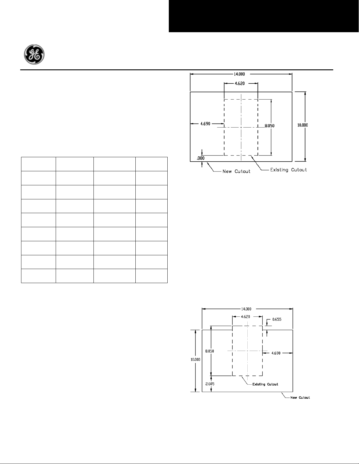
Panel Cutout
Figure 2 shows the 14” x 10” cutout required using the
existing cutout as reference (dashed). Once cutout is
complete, mount the standard trim plate using #8-32
screws and torque to 5 in-lbs.
The 800A Power Break II design is similar in dimension to
the 800A Power Break I breaker. The only modification
required is the panel cutout. Begin process by removing
existing breaker from equipment.
Panel Cutout
A 14” x 10” cutout is required for the Power Break II
breaker to fit. Figure 1 shows the new front panel cutout
using the existing cutout as reference (dashed line in
Figure 1). Once cutout is complete, mount the standard
trim plate using #8-32 screws and torque to 5 in-lbs.
Figure 2: 1600 - 2000A Panel Cutout
1
Page 2
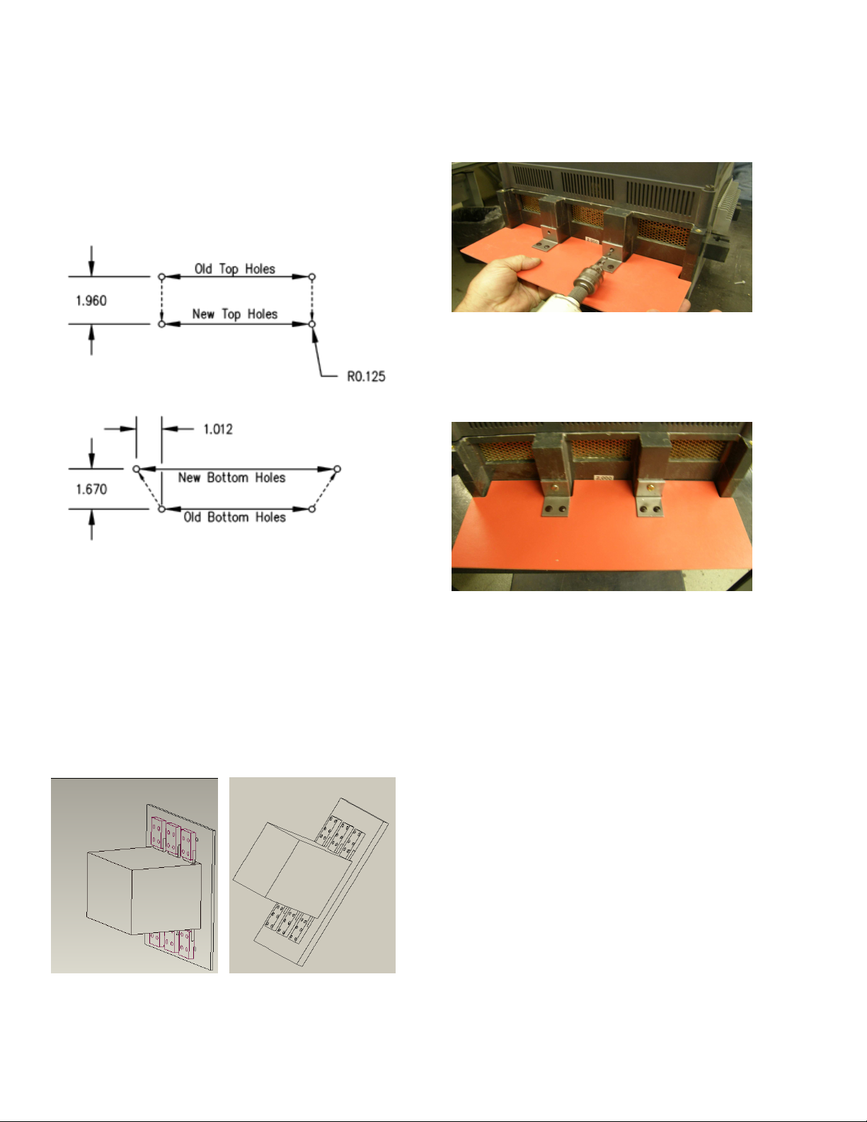
Mounting Hole Relocation
Line Shield
Since the mounting holes for the Power Break II breaker
do not align with the holes in panel, new mounting holes
need to be drilled on the panel breaker mounting space.
Figure 3 shows the new locations for the 1600A-2000A
breakers. A 1:1 scale template is provided with the kit to
guide in the drilling of the holes, which should be made for
a ¼-20 tap. It is important to note that new non
magnetic mounting boards or channels may need to be
installed in the existing housing to accommodate for the
relocation of the mounting holes.
Due to the addition of the strap extensions, a shield is
required in the line side of the breaker. To install, place line
shield so that the top of mounting bracket aligns with
where breaker base and mid cover meet. Mark the area to
drill using a drill or white pencil (Figure 5).
Figure 5: Mark the Area for Drilling Holes
After marking the area, drill the holes to a depth of
approximately 0.75” using a 0.156” bit. Finally install the
line shield using #10-16 thread cutting screws provided
(Figure 6).
Figure 3: 1600-2000A Mounting Hole Relocation
Line /Load Strap Extensions
The Power Break I 1600A and 2000A breakers are longer
than their Power Break II counterparts. To compensate
for the difference in length, 6 line strap extensions are
provided with the conversion kit. Please note that the
length for the straps is different, 1600A is 4” long and
2000A is 5.25”. Bolt the extensions using 1/2” screws to the
line and load straps to a torque of 300 in-lbs. The
extensions should be bolted as shown on Figure 4.
Figure 6: Line Shield Installation
Breaker Installation
Ensure that all accessory connections are secure. Line up
mounting holes with enclosure. Place the bolts and tighten
to 300 in-lbs.
Neutral Sensor
For Power Break I connected in a three-phase four-wire
system please note the following regarding neutral sensor:
- If the Power Break I has an Enhanced MVT Plus/PM
trip unit, the neutral sensor can be reused
- If the Power Break I has an Original MVT, RMS-9, or
EPIC trip unit, the neutral sensor can be reused.
However, a 1:1 isolation CT might be required to
properly isolate from multiple grounds.
- For Power Break I with any other trip unit, the
neutral sensor must be replaced. See Page 31, GET8052C for Neutral Sensor Options.
Figure 4: Installed 1600A (left) and 2000A (right) Strap Extenders
2
Page 3

2500-4000A Stationary Breaker
Breakers with a frame size from 2500A to 4000A are
considered large frame. They include the 2500A front
connected (FC), 2500A back connected (BC), 3000A FC,
3000A BC, and 4000A FC. As in the case of the 800A
breakers, the Power Break II designs are similar in
dimensions to the Power Break I breakers. Only the panel
cutout needs to be modified to be ready for breaker
installation. Begin process by removing existing breaker
from equipment.
Panel Cutout
The 2500A FC, 2500A BC, 3000A FC, and 3000A BC require
a 14” x 16.07” cutout for the Power Break II breaker to fit.
Figure 8 shows the new front panel cutout using the
existing cutout as reference (red line in Figure 7).
Trim Plate
Once cutout is complete, mount the provided trim plate
using #8-32 screws and torque to 5 in-lbs. Please note the
trim plate is determined by the Power Break I that is to
be replaced. Figure 9 shows the 2 types of trim plates used
in large frame breakers. If the equipment had an
electrically operated Power Break I, SSF40TPCCE kit
should be used (left). If the breaker was Manually operated,
use SSF40TPCCM kit (right).
Figure 9: Trim Plates: Electrical (left), Manual (right)
Figure 7: 2500A FC, BC, 3000A FC, and BC Panel Cutout
The cutout for the 4000A breaker should be 14” by 13.54”
and it is shown in Figure 8.
Figure 8: 4000A Panel Cutout
Figure 10: Trim Plates: Electrical (left), Manual (right)
Breaker Installation
Ensure that all accessory connections are secure. Line up
mounting holes with enclosure. Place the bolts and tighten
to 225 in-lbs for 2500-3000A breaker, or 300 in-lbs for a
4000A.
Neutral Sensor
For Power Break I connected in a three-phase four-wire
system please note the following regarding neutral sensor:
- If the Power Break I has an Enhanced MVT Plus/PM
trip unit, the neutral sensor can be reused
- If the Power Break I has an Original MVT, RMS-9, or
EPIC trip unit, the neutral sensor can be reused.
However, a 1:1 isolation CT might be required to
properly isolate from multiple grounds.
- For Power Break I with any other trip unit, the
neutral sensor must be replaced. See Page 31, GET8052C for Neutral Sensor Options.
3
Page 4

These instructions do not cover all details or variations in equipment nor do they provide for every possible contingency that may be met in
operation, or maintenance. Should further information be desired or should particular problems arise that are not
Appendix: Additional Information
Table 1: Weights of Various PBII Breaker Frame Sizes
Frame
Rating
800A
1600A
2000A
2500A
Front Connect
2500A
Back Connect
3000A
Back Connect
3000A
Front Connect
4000A
Table 2: Bolt Sizes and Recommended Mounting Torques for Bus Connections.
Frame Rating Bolt Torque (in-lbs)
800A (1) ½ in 300
1600A-2000A (2) ½ in 300
2500A
3000A
4000A (6) ½ in 300
Operation
Type
Manual
Electrical
Manual
Electrical
Manual
Electrical
Manual
Electrical
Manual
Electrical
Manual
Electrical
Manual
Electrical
(4) 3/8 in 225
(4) 3/8 in 225
Weight (lbs)
71
80
79
88
178
187
167
176
179
188
216
225
320
329
Table 3: Minimum Ventilation Cutout Areas
PBI PBII
Stationary Total Top Bottom Total Top Bottom
800A
1600A
2000A
2500A
3000A
4000A
N/A N/A N/A N/A N/A N/A
60 30 30 60 30 30
160 80 80 86.4 43.2 43.2
160 80 80 160 80 80
270 135 135 270 135 135
280 140 140 270 135 135
connection with installation,
covered sufficiently for the purchaser’s purposes, the matter should be referred to the GE Company.
GE Industrial Solutions
General Electric Company
41 Woodford Ave., Plainville, CT 06062
DEH41502 R01 © 2010 General Electric Company
4
 Loading...