

Page 1
g
GEH–6520A
Power Break® II Circuit Breaker
Accessories
Undervoltage Release
480 & 600 Vac
Introduction
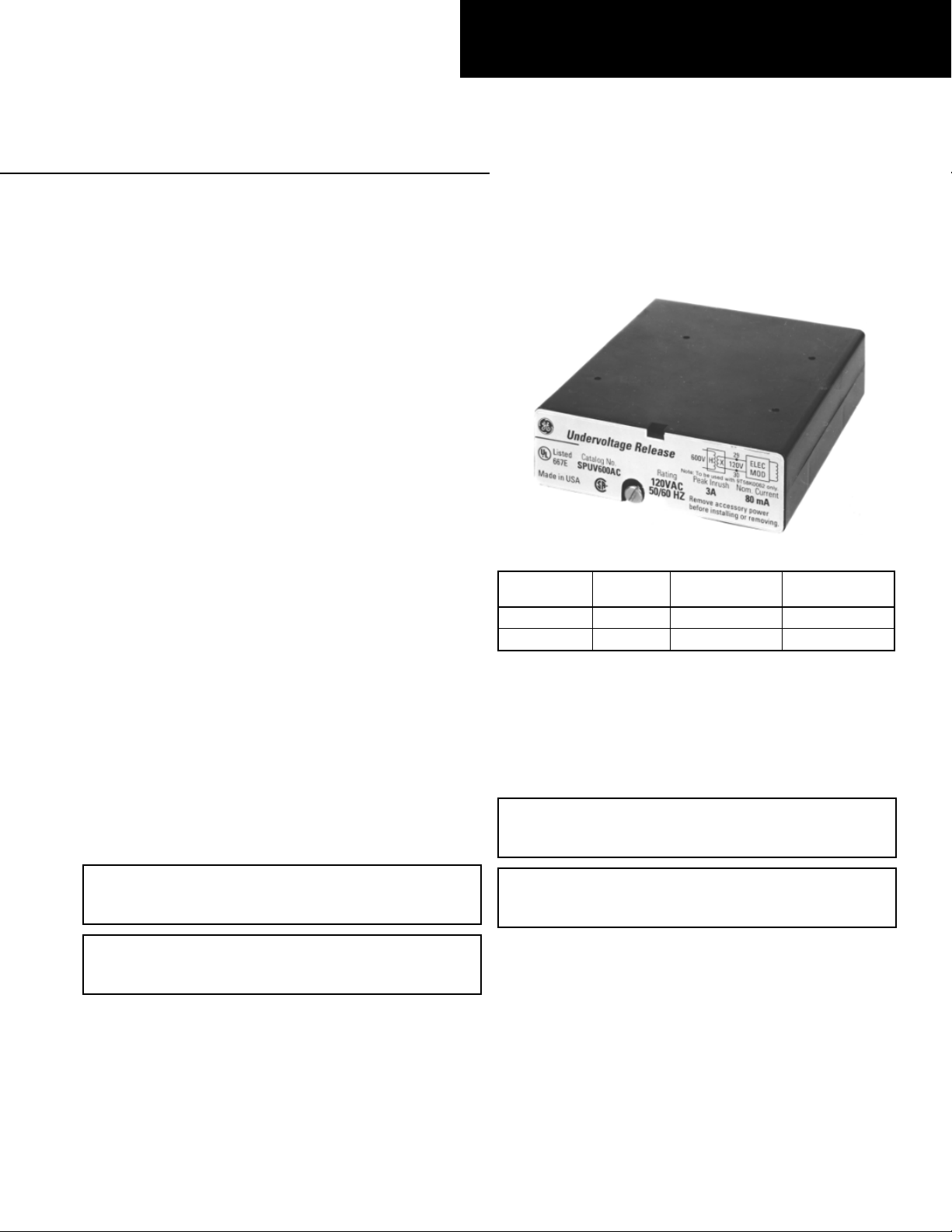
The Undervoltage Release (UVR) accessory, shown in Figure
1, can be installed in 800–4000 ampere frame Power Break®
II circuit breakers. This accessory trips the circuit breaker when
the input control voltage drops to 35–60% of its rated value
and prevents an open breaker from closing until the input
control voltage is greater than 8 0% of the rated value.
In addition to providing a trip signal to the breaker, the UVR
accessory can be set up to interact with other Power Break II
accessories, when used with a MicroVersaTrip Plus™ or
MicroVersaTrip PM™ Trip Unit. DIP switches on the rear of
the breaker Trip Unit can configure the UVR accessory to
activate a Bell Alarm–Alarm Only accessory or a Bell Alarm
with Lockout accessory when a UVR trip occurs. The Accessory
Configuration section below describes how this can be done. If
the breaker is equipped with a Power+™ Trip Unit, it is
configured so that only protection trips will activate a Bell
Alarm–Alarm Only or Bell Alarm with Lockout.
The catalog numbers for the UVR for 480 and 600 Vac
applications are listed in Table 1. Voltage and current ratings
in Table 1 are given at the input of the transformer. The
voltage and current ratings at the input of the UVR accessory
are equal to that of the SPUV120AC accessory. Input voltage is
120 Vac, peak inrush current is 3 A, and the nominal RMS
current is 80 mA.
Operation
Apply control voltage to the primary of the s upplied step-down
transformer. The secondary of the transformer is connected to
terminals 29 and 3 0 of the terminal strip on the right side of
the breaker.
Figure 1. Undervoltage Release.
Catalog
Number
SPUV480AC 480 Vac 750 20
SPUV600AC 600 Vac 600 16
➀
Rated for 50/60 Hz. Rating is 120 Vac without step-down
transformer.
➁
Peak inrush current is present for 2–6 ms after activation. This
number is provided so that fuses and supplies can be chosen
appropriately.
Table 1. Catalog numbers and voltages for the Undervoltage Release.
Voltage
Rating
➀
Current, mA
Peak Inrush
Nominal RMS
➁
Current, mA
Installation
WARNING: Before installing any accessories, turn the breaker
OFF, disconnect it from all voltage sources, and discharge the
charging springs.
WARNING: 480 Vac and 600 Vac Undervoltage Release
accessories must be used with the supplied step-down
transformer.
AVERTISSEMENT: Les modules de déclenchement à manque
de tension 480 Vac et 600 Vac doivent être utilisés avec le
transformateur abaisseur de tension qui est fourni.
When the applied control voltage is above 80% of the UVR’s
rated value, the breaker can be closed. When the voltage drops
to 35–60% of the rated value, the UVR will trip the breaker.
AVERTISSEMENT: Avant d’installer toute accessoire, mettre
le disjoncteur en position OFF, le déconnecter de toute tension
d’alimentation, et décharger les ressorts d’armement.
The Undervoltage Release is installed in the access ory
compartment through the front of the circuit breaker in the
position shown in Figure 2.
Use the following procedure to install the UVR accessory into
the UVR slot in the accessory compartment of the circuit
breaker:
1. Open the hinged door over the ac cessory compartment and
Trip Unit.
2. To remove an existing accessory, loosen the accessory
locking screw and pull the accessory out with the Rating
Plug Removal Tool (catalog number TRTOOL).
Page 2
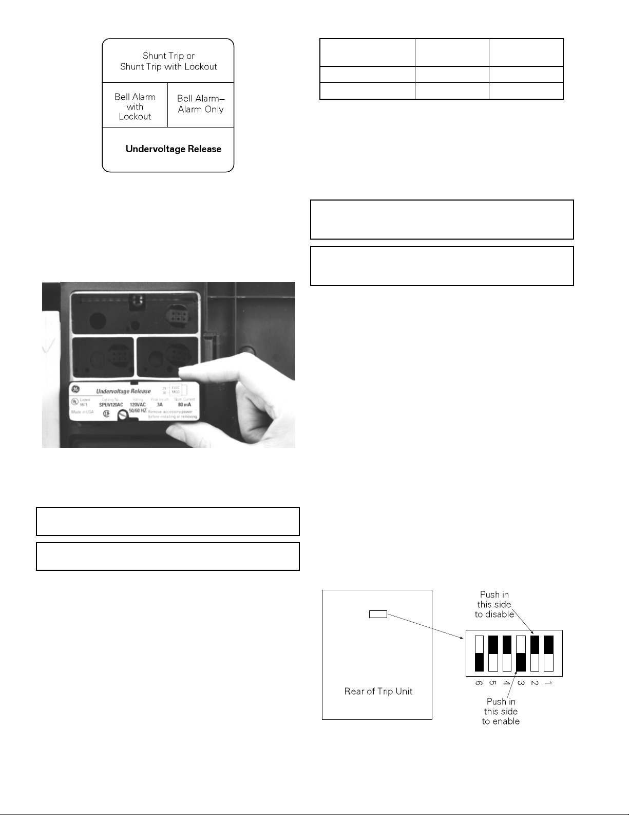
Figure 2. Accessory compartment on front of circuit breaker, with
Undervoltage Release slot indicated.
3. Insert the UVR accessory into the proper slot, as
illustrated in Figure 3. The UVR accessory is keyed for
the correct slot in the accessory compartment. I f the
accessory cannot be fully seated in the compartmen t, check
that the compartment position is correct.
Catalog Number/
Control Voltage
9T58K0042 / 480 V H1, H4➀ X1, X2
9T58K0062 / 600 V H1, H4 X1, X3
➀ A jumper must be placed from H2 to H3.
Primary
Connections
Secondary
Connections
Table 2. Primary and secondary connections for step-down
transformers.
8. Connect the secondary side of the transformer, marked as
the X-numbered terminals, to terminals 29 and 30 of the
terminal block on the right side of the breaker. Table 2
lists the correct transformer secondary taps.
WARNING: 480 Vac and 600 Vac Undervoltage Release
accessories must be used with the supplied step-down
transformer.
AVERTISSEMENT: Les modules de déclenchement à manque
de tension 480 Vac et 600 Vac doivent être utilisés avec le
transformateur abaisseur de tension qui est fourni.
9. Test the UVR to ensure proper operation, according to the
procedures below.
10. Reconnect power to the circuit breaker and any other
accessories.
11. Close and lock or seal the door over the accessory
compartment and Trip Unit to prevent unauthorized
changes to Trip Unit settings and to keep contaminants
out of empty accessory slots.
Figure 3. Inserting the Undervoltage Release into the accessory
compartment.
4. Tighten the locking screw on the front of the accessory
until it is snug (torque of 9 in-lb.)
CAUTION: Overtightening the locking screw may damage or
distort the case of the accessory.
ATTENTION: Le serrage excessif de la vis de verrouillage
peut déformer le boîtier d’accessoire.
5. If the breaker is equipped with a MicroVersaTrip Plus or
MicroVersaTrip PM Trip Unit, the UV R accessory can be
configured to activate installed Bell Alarm–Alarm Only or
Bell Alarm with Lockout accessories when a UVR trip
occurs, with the procedure described in the Accessory
Configuration section.
6. Mount the supplied step-down transformer near the circuit
breaker.
7. Connect the control wiring for the UVR to the primary
side of the transformer, marked as the H-numbered
terminals. Table 2 lists the correct transformer primary
taps.
Accessory Configuration
This section only applies if Bell Alarm–Alarm Only or Bell
Alarm with Lockout accessories are installed in the breaker,
along with a MicroVersaTrip Plus or MicroVersaTrip PM Trip
Unit. If the breaker is equipped with a Power+ Trip Unit, the
factory default settings, listed in Table 3, can not be changed.
The UVR accessory can be configured to activate the Bell
Alarm–Alarm Only or Bell Alarm with Lockout accessories if a
UVR trip occurs. The configuration can be changed by removing
the Trip Unit from the brea ker, setting the DIP switches on the
rear of the Trip Unit, and reinstalling the Trip Unit. Figure 4
illustrates the Trip Unit read DIP switches and their functions.
Table 3 lists the switch functions and the factory settings for
each.
Figure 4. Accessory switch on the rear of the MicroVersaTrip Plus™ or
MicroVersaTrip PM™ Trip Unit, showing the factory settings (solid
part indicates that the switch is pushed in on that side).
Page 3

Switch
1 Disabled
2 Disabled
3 Enabled
4 Disabled
5 Disabled
6 Enabled
Factory
Setting Function
Shunt trip activates Bell Alarm–Alarm
Only
UVR trip activates Bell Alarm–Alarm
Only
Protection trip activates Bell
Alarm–Alarm Only
Shunt trip activates Bell Alarm with
Lockout
UVR trip activates Bell Alarm with
Lockout
Protection trip activates Bell Alarm
with Lockout
Table 3. Accessory switch settings, including factory defaults.
Description of Switch Settings
Following are descriptions of the effects of each accessory switch
when it is enabled:
1. When a Shunt Trip accessory causes the breaker to trip,
the contacts of the Bell Alarm–Alarm Only also change
state. (The factory switch setting is disabled.)
2. When an Undervoltage Release accessory causes the
breaker to trip, the contacts of the Bell Alarm–Alarm Only
also chang e state. (The factory switch setting is disabled.)
3. When a protection trip (long-time, short-time,
instantaneous, ground-fault, or protective-relay) occurs,
the contacts of the Bell Alarm–Alarm Only also change
state. (The factory switch setting is enabled.)
4. When a Shunt Trip accessory causes the breaker to trip,
the contacts of the Bell Alarm with Lockout also change
state. (The factory switch setting is disabled.)
5. When an Undervoltage Release accessory causes the
breaker to trip, the contacts of the Bell Alarm with
Lockout also change state. (The factory switch setting is
disabled .)
6. When a protection trip (long-time, short-time,
instantaneous, ground-fault, or protective-relay) occurs,
the contacts of the Bell Alarm with Lockout also change
state. (The factory switch setting is enabled.)
Procedure for Changing Switch Settings
Change the accessory switch settings with the following
procedure:
3. Pull the Trip Unit locking lever to the right, then hold the
Trip Unit near the battery cover and lift it straight out of
the breaker.
4. Refer to Figure 4 and Table 3 to determine the switches
to be changed.
5. Push in the appropriate “Enable” or “Disable” side of the
switch.
6. Confirm all switch settings before reinstalling the Trip
Unit in the breaker.
7. Pull the Trip Unit locking lever to the right. While
holding the lever, carefully align the connector on the rear
of the Trip Unit with the connector in the breaker. Press
down on the Trip Unit, while holding it near the battery
cover. When the Trip Unit is fully seated, slide the locking
lever back to the left.
8. Reinstall the breaker top cover and tighten the four #1032 screws to 32 in-lb.
9. Replace the trim plate and tighten the four #8-32 screws
to 20 in-lb.
10. Verify that the switch settings are correct by inducing
breaker trips from the UVR and Shunt Trip or Shunt Trip
with Lockout (if present) and checking the responses of
the Bell Alarm–Alarm Only and Bell Alarm with Lockout
accessories.
Test Procedure
Use the following procedure to test the UVR for proper
operation.
1. Open the breaker.
2. Turn off the power to the UVR.
3. Try to manually close the breaker; the breaker should not
close.
4. Apply at least 80% of the rated voltage specified on the
UVR name plate to the UVR control inputs.
5. Try to close the breaker; it should close as normal.
6. If a MicroVersaTrip Plus or MicroVersaTrip PM Trip
Unit is installed, check that the Trip Unit display is active
(powered).
7. With the breaker closed, reduce the UVR control voltage to
35–60% of the rated voltage; the breaker should trip
within 0.5 second.
8. If a Bell Alarm–Alarm Only or Bell Alarm with Lockout is
present, ensure that they activate (or do not activate) as
selected by the MicroVersaTrip Plus or MicroVersaTrip
PM Trip Unit DIP switches.
WARNING: Before beginning this procedure, turn the breaker
OFF, disconnect it from all voltage sources , and discharge the
closing springs.
AVERTISSEMENT: Avant de commencer cette procédure,
mettre le disjoncteur en position OFF, l e déconnecter de toute
tension d’alimentation, et désarmer les ressorts de fermeture.
1. Loosen the four #8-32 screws on the breaker trim-plate
assembly and remove the trim plate.
2. Loosen the four #10-32 screws at the corner of the breaker
cover. Remove the cover from the breaker face.
Page 4

Trouble-Shooting
p
The following guide i s provided for trouble-shooting and
situation. Contact the ED&C Customer Support Center at 800843-3742 if any problem is not r esolved by these procedures.
isolating common problems. It does not cover every possible
Symptom Possible Cause Corrective Action
The UVR accessory will
1.
not insert completely in
the breaker.
The accessory is inserted
incorrectly.
Ensure that the accessory is inserted in the correct slot, as
in Figure 2, and that the label is upright. Ensure that the
accessory is completely seated and that the screw is
tightened.
The breaker closes when
2.
the UVR is de-energized.
The breaker will not close
3.
when the UVR is
energized.
The breaker does not trip
4.
when UVR control power
is removed.
The Bell Alarm–Alarm
5.
Only or Bell Alarm with
Lockout does not trip
correctly (trips when it
shouldn’t or doesn’t trip
when it should).
The UVR lockout plunger is not
engaged.
The UVR is actually energized.
The UVR solenoid is not
energized.
The transformer connections are
incorrect.
The breaker is not closed.
UVR control power is actually
still applied.
The UVR trip connection is poor.
The Bell Alarm–Alarm Only or
Bell Alarm with Lockout
configuration switches on the
back of the MicroVersaTrip Plus
or MicroVersaTrip PM Trip Unit
are not properly set. Note that
this feature is not available with
Power+™ Trip Units.
The Bell Alarm–Alarm Only or
Bell Alarm with Lockout
accessory is improperly installed.
Remove the UVR accessory. Check that the lockout
plunger protrudes approximately 1⁄4 inch out of the
accessory; if it does not, replace the UVR. If the plunger
length is correct, reinsert the UVR, ensuring good
alignment of the accessory to the pocket. Ensure that it is
completely seated, flush with the top of the pocket, then
tighten the screw to 9 in-lb.
Check that the control power to the UVR is off.
Check that UVR control power is applied at greater than
80% of the UVR rated voltage. Check that the accessory is
completely inserted; reinsert if necessary.
Note that an otherwise unpowered Trip Unit is powered
up by an energized UVR accessory.
Ensure that steps 6, 7, and 8 in the Installation section
have been followed correctly.
Verify that the breaker is closed.
Check that the UVR control power has been removed or
that its voltage is less than 35% of the rated value.
Check that the UVR accessory is completely inserted.
Check that the Trip Unit is seated correctly. If the Trip
Unit was removed to set the switches, check that it has
been correctly installed; remove and reinstall, if necessary.
Follow the procedure to remove the Trip Unit and set the
switches. Check that the switches have been set correctly.
See the Trouble-Shooting Guide for the Bell Alarm with
Lockout in GEH-6278 or the Bell Alarm–Alarm Only in
GEH-6275.
These instructions do not cover all details or variations in equipment nor do they provide for every possible contingency that
may be met in connection with installation, operation, or maintenance. Should further information be desired or should
articular problems arise that are not covered sufficiently for the purchaser’s purposes, the matter should be referred to the
GE Company.
g
GE Electrical Distribution & Control
General Electric Company
41 Woodford Ave., Plainville, CT 06062
GEH-6520A 0697 © 1997 General Electric Company
 Loading...