

Page 1

Basic Installation and User’s Guide
for the Millennium II Controller
J85501P-1
Product Manual
Select Code 167-792-181
Comcode 108994645
Issue 3
January 2008
Page 2

Notice:
The information, specifications, and procedures in this manual are subject to change
without notice. Lineage Power assumes no responsibility for any errors that may appear
in this document.
© 2008 Lineage Power
All International Rights Reserved
Printed in U.S.A.
Page 3

Basic Installation and User’s Guide for the Millennium II Controller
Table of Contents
1 Introduction.................................................................................................................... 4
Millennium II.................................................................................................................. 4
Customer Service Contacts............................................................................................. 5
2 Product Description....................................................................................................... 6
Overview......................................................................................................................... 6
Feature Summary............................................................................................................ 6
General Specifications .................................................................................................. 11
Hardware....................................................................................................................... 12
3 Safety............................................................................................................................. 15
Safety Statements.......................................................................................................... 15
Warning Statements and Safety Symbols..................................................................... 17
Precautions.................................................................................................................... 18
Special Installation Notes ............................................................................................. 19
4 New Installations.......................................................................................................... 21
Controller Connections ................................................................................................. 23
Installing Circuit Packs................................................................................................. 24
Thermal Probes ............................................................................................................. 28
USB Interface................................................................................................................ 29
Wiring Alarm Outputs .................................................................................................. 29
Wiring Alarm and Control Inputs................................................................................. 32
Fuses ............................................................................................................................. 35
Front Panel Display....................................................................................................... 35
Controller Defaults........................................................................................................ 39
Controller Display Menu Maps .................................................................................... 46
5 Acceptance Testing ...................................................................................................... 58
Introduction................................................................................................................... 58
Tools and Test Equipment ............................................................................................ 58
Test Precautions............................................................................................................ 58
Test Sequences.............................................................................................................. 59
6 Controller Retrofits ..................................................................................................... 67
Millennium Basic Controller Retrofit........................................................................... 67
Millennium Intelligent Controller Retrofit ................................................................... 85
7 Troubleshooting ......................................................................................................... 104
Controller Circuit Pack ............................................................................................... 104
Option Cards ............................................................................................................... 104
Controller Alarm Descriptions.................................................................................... 104
Clear Events................................................................................................................ 110
Uninstall Devices........................................................................................................ 111
8 Spare Parts ................................................................................................................. 112
9 Product Warranty...................................................................................................... 113
Revision History............................................................................................................ 115
Issue 3 January 2008
3
Page 4

Basic Installation and User’s Guide for the Millennium II Controller
1 Introduction
Millennium II
The J85501P-1 Galaxy Millennium II controller is the next generation full-featured
power system controller from Lineage Power. It provides control, monitoring, and alarm
monitoring functions over a multi-drop serial interface that interconnects system
rectifiers, converters, Bay Interface Cards (BICs), and other serial devices. It utilizes
robust RS-485 serial busses that support the Galaxy Protocol (GP) to communicate to
these devices. The Millennium II has a plethora of I/O and monitoring options. It can
monitor and control battery plants containing up to 64 Galaxy serial rectifiers, up to 16
serial converters, and up to 32 BICs. A maximum combination of 85 GP nodes can be
directly managed on the rectifier serial bus. The Millennium II performs many functions
described more thoroughly in following sections. Following is a high level view.
• Alarm Detection, Identification, and Reporting
• System and Component Status
• System and Feature Configuration
• System Alarm Thresholds
• Battery Management (Slope Thermal Compensation/Recharge Current Limit)
• Battery discharge testing
• Reserve Time Prediction
• Selective high/low voltage shutdown
• Float/Boost Mode Control
• Low Voltage Disconnect Management
• Remote Access Control And Multiple Level Password Security
• Control and Operations
• History
• Statistics
This controller replaces the existing +24V and -48V versions of the Millennium
controller with a single unit. While becoming easier to use, the Millennium II adds
additional functionality to the comprehensive feature set now provided by the existing
Millennium. The Millennium II is
separate Independent (Basic), Intelligent, and network interface circuit packs of the
existing Millennium controller have been integrated into a single standard board offering
with the Millennium II. This eliminates the need to manage multiple boards for features
as well as plant voltage. Intelligent functionality with remote 10/100 Base-T network
access capability to display power system operating status and available information via
the world wide web (internet) or your enterprise network (intranet) using standard
browsers such as Microsoft Internet Explorer® or Netscape® Navigator is now the
standard offering.
Issue 3 January 2008
Lineage Power’s new flagship controller product. The
4
Page 5
Basic Installation and User’s Guide for the Millennium II Controller
Not only are the software features of the Millennium all contained in the Millennium II,
the new controller is physically backwards compatible for field upgrades and
replacements. The Millennium II can also be used as an upgrade to the door mounted
Galaxy Vector controller When performed, this installation adds newer and more
available technologies to the power system. The old Millennium chassis is replaced with
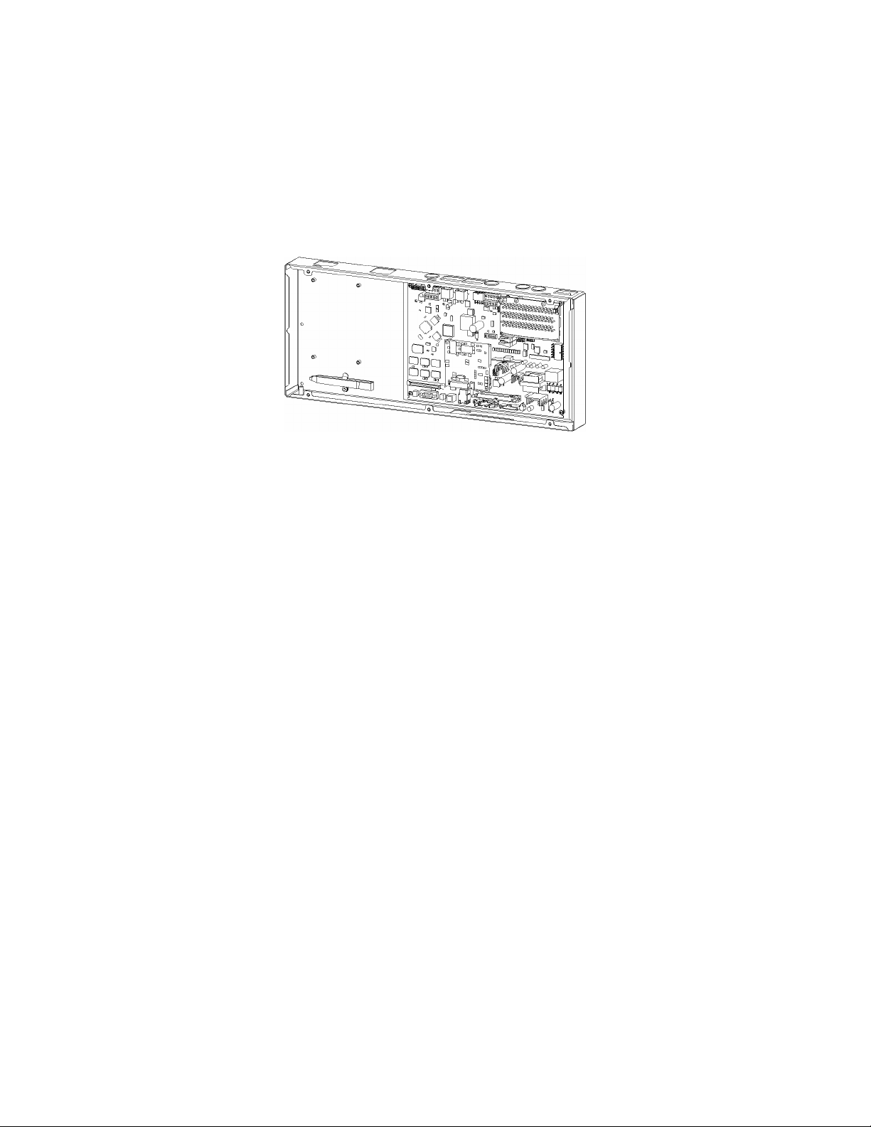
the new Millennium II chassis shown in the figure following. All existing and future GPS
cabinet systems remain supported by the Millennium II.
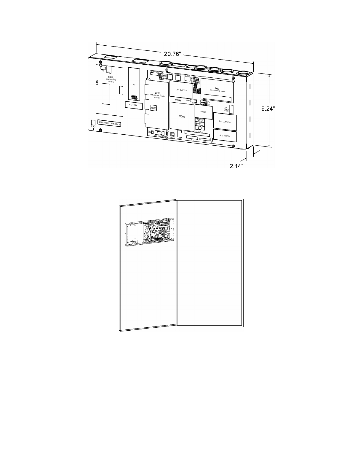
Figure 1-1:Galaxy Millennium II Controller
Customer Service Contacts
Customer Service, Technical Support, and Warranty Service
For customers in the United States, Canada, Puerto Rico, and the US Virgin Islands, call
1-800-THE-1PWR (1-800-843-1797). This number is staffed from 7:00 am to 5:00 pm
Central Time (zone 6), Monday through Friday, on normal business days. At other times
this number is still available, but for emergencies only. Services provided through this
contact include initiating the spare parts procurement process, ordering documents,
product warranty administration, and providing other product and service information.
For other customers worldwide the 800 number may be accessed after first dialing the
AT&T Direct country code for the country where the call is originating, or you may
contact your local field support center or your sales representative to discuss your
specific needs.
Customer Training
Lineage Power offers customer training on many Power Systems products. For
information call 1-972-284-2163. This number is answered from 8:00 a.m. until 4:30
p.m., Central Time Zone (Zone 6), Monday through Friday.
On-Line Power Systems Product Manuals and Software
Power Systems on-line product manuals and software are available on-line. Software
includes Easy View and SNMP MIB.
Issue 3 January 2008
5
Page 6

Basic Installation and User’s Guide for the Millennium II Controller
2 Product Description
Overview
The Millennium II has been designed to be a complete power system monitor and
controller with a variety of alarming and remote access capabilities that complies with all
relevant regulatory requirements, respectively. It is the nerve center of the battery plant
that utilizes serial monitored and controlled rectifiers, converters, and system peripherals.
It monitors and controls the plant rectifiers, distribution, and batteries. It can also monitor
and control peripheral power equipment, including standby generators, converter plants,
and inverters.
The Millennium II monitors and control battery plants containing up to 64 Galaxy serial
rectifiers, up to 16 serial converters, and up to 32 Bay Interface Cards (BICs). A
maximum combination of 85 GP nodes can be directly managed on the rectifier RS485
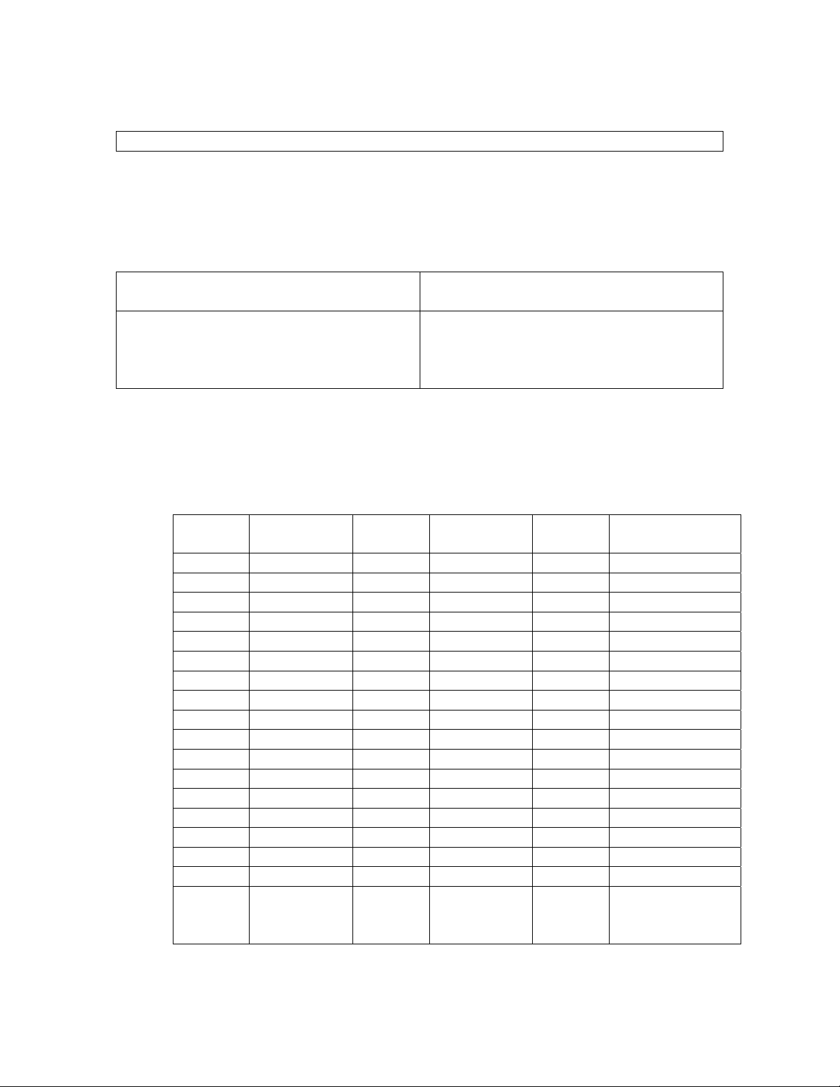
serial bus. The following table contains the Lineage Power rectifiers that can interface with
the Galaxy Millennium II:
Table 2-A: Rectifiers That May Be Used With Millennium II
Model Vdc Current
570A -48V 100A
595A, 595B,
595C, 595LTA,
595LTB
596A / 596D -48V 50A / 100A
596B +24V 100A / 125A
596F +24V 100A
NP +24V / -
CPS6000 QS86X -48V 7.5A – 50A
AC3000 -48V 60A
-48V 200A/220A
24A – 50A
48V
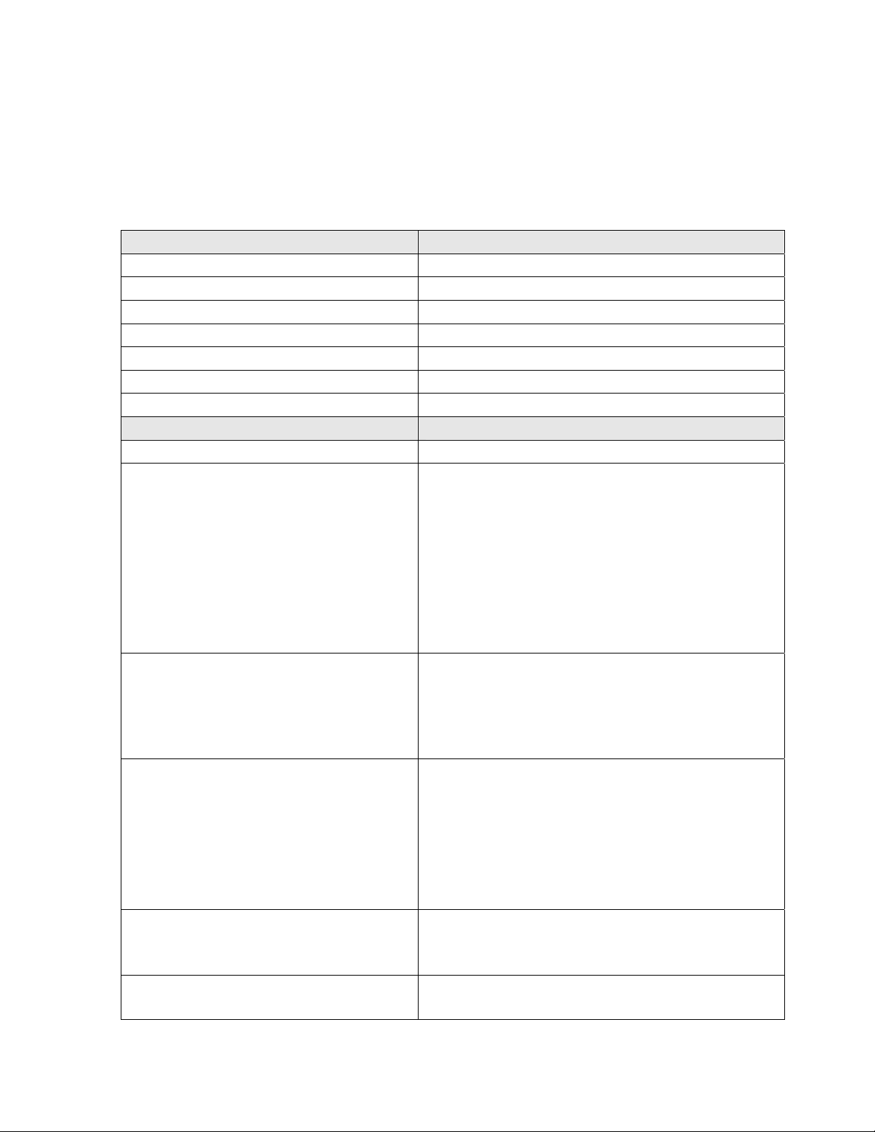
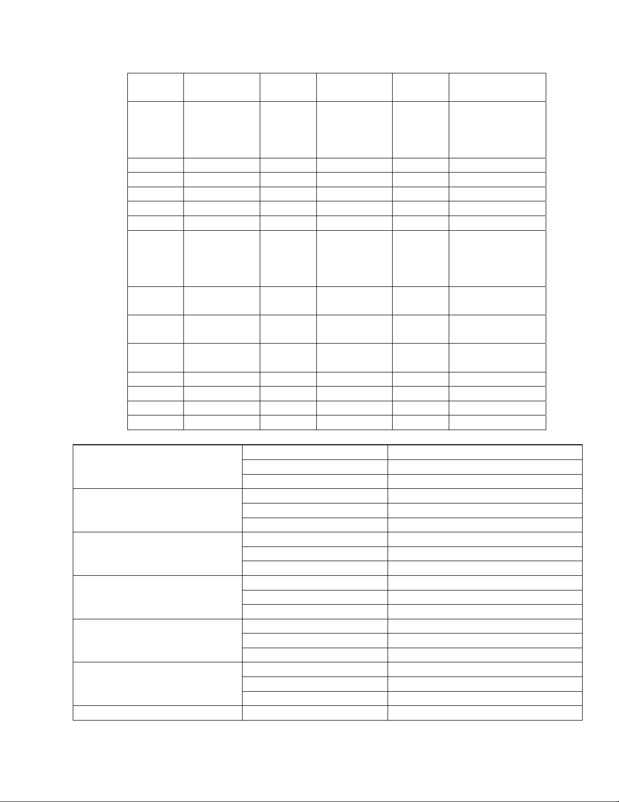
Feature Summary
The Millennium II has combined and enhanced its Millennium predecessor’s Basic,
Intelligent, and Network functionality into its standard offering. This controller unit
supports
the features available in the Millennium II.
Lineage Power‘s most extensive controller feature set. Following is a summary of
Issue 3 January 2008
6
Page 7

Basic Installation and User’s Guide for the Millennium II Controller
Standard System Features
Monitoring and control of up to
85 RS485 serial connected
devices
Alarms
• Maximum of 64 serial switchmode rectifiers
• Maximum of 32 Bay Interface Cards (BICs)
• Maximum of 16 serial converters
• Standard and custom User Defined system
alarms
• Alarm test
• Alarm cut-off
• Multiple-level alarm severity: Critical, Major,
Minor, Warning, and Record-Only
Rectifiers
• Automatic rectifier restart
• Reserve engine transfer
• High Voltage Shutdown
• Energy management
• Remote rectifier (on/off) control
• Automatic rectifier sequence control
• N + X redundancy check
• Digital voltage regulation and rectifier load
share
Contactor/Disconnect Control
• Low Voltage Load
• Low Voltage Battery
Interfaces
• Enhanced Front Panel Display
• Local PC Port
• Modem
• LAN (Gateway Card)
• X.25/TL1
Peripheral Monitoring and
Control
• Up to 512 monitoring channels
• On board generic voltage channel
• On board 4-20mA transducer interface
Maintenance Tools
• User Programmable Alarms
• History
• Statistics
• Diagnostics
• Derived Channels
• Inventory Management
• Configuration Backup/Restore
Memory
• Non-Volatile
• Battery Backed
• Remote and Local Software Upgrade
Issue 3 January 2008
7
Page 8

Basic Installation and User’s Guide for the Millennium II Controller
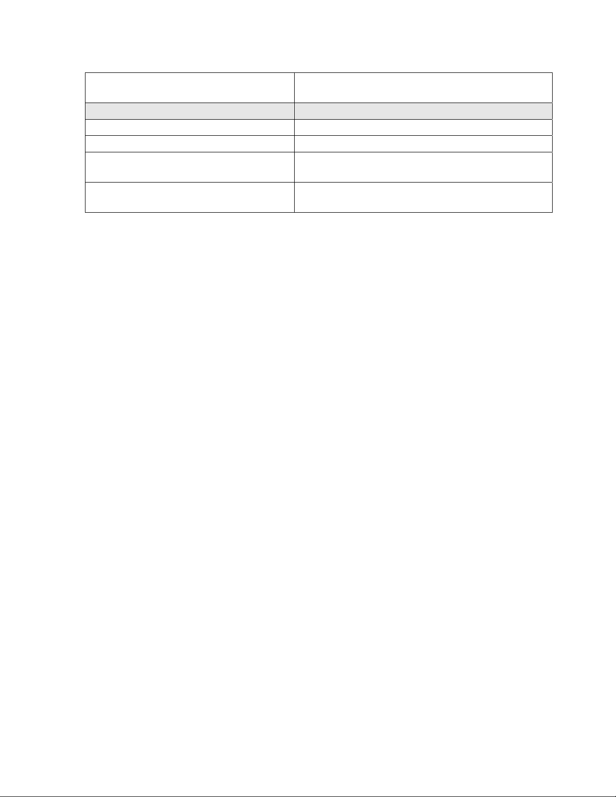
Enhanced Front Panel User Interface
Cabinet door mounted
LCD
• Front access without opening the cabinet door
• 8-line by 40-character (240 x 64) backlit
display with digital contrast adjust
Menu Driven User Interface
• Re-designed user friendly menu driven LCD
with similar push-button membrane switch
interface
• Menu structure similar to other Lineage Power
controllers
Audible Alarm Buzzer
• Integrated on display assembly
• May be Enabled/Disabled
LEDs
• 12 individual user configurable status LEDs:
Critical, Major, Minor, Normal, AC System,
Battery, Controller, Distribution, Rectifier,
Remote Modules, Modem, and Battery On
Discharge
Test Jacks
Local Port
• Used to verify displayed system bus voltage
• DB-9 RS232 system port for local terminal
access or event log printing
• ANSI T1.317 serial access
• EasyView Windows-based software for
configuration and reporting
• Ground referenced
Compatibility
• Backwards compatible to existing Millennium
Remote Access And Features
Integrated 10/100Base-T
Ethernet Network capability
Optional Modem access
Issue 3 January 2008
• Supports TCP/IP Version 5, SNMP Version
2c, SMTP, TL1, DHCP, Telnet, FTP
• Standard and custom web pages for standard
browsers (HTTP)
• Compatible to Galaxy Manager
• Standard shielded RJ-45 interface referenced
to chassis
• Remote access via internal BSM5 Modem
option (56k bps Modem)
• Remote access capability via external Modem
• Callback security
8
Page 9

Basic Installation and User’s Guide for the Millennium II Controller
Optional BSW Dataswitch
TL1
Easy View PC User Interface
Security
Battery Management
Slope Thermal Compensation
(STC)
Recharge Current Limit
Reserve Time Prediction
Battery Discharge Testing
Float/Boost Mode Control
Temperature Disconnect
Emergency Power Off
• Connections to 3 standard RS232 devices for
pass-through and alarm management
• BSN extension to provide 3 additional RS232
serial connections
• Configurable RS-232/485 port for remote via
TL1/X.25
• Windows-based software, for configuration
and reporting through local terminal or
• Modem connections
• Multiple password-protected security levels
• Dip Switches
• Enhanced Security Features enable or disable
many controller features
• High temperature compensation
• Low temperature compensation
• Step temperature
• STC Enable/Disable
• Low temperature Enable/Disable
• mV/°C adjustments
• Control rechargerate for batteries
• Supports a variety of batteries
• Use configurable Low Reserve Time Alarm
• Integrated “At Rate Calculator” for estimation
purposes
• Manual
• Periodic
• Plant Battery Test (PBT) input driven
• Battery Discharge trace data
• Manual Timed Boost- Locally T1.317 and
remotely initiated
• External Timed Boost
• Battery Thermal Protect module Boost (BTP)
• Auto Boost terminated by time or current
• Manual front panel Boost
• Programmable high temperature
• User programmable
Issue 3 January 2008
9
Page 10
Basic Installation and User’s Guide for the Millennium II Controller
Integrated Monitoring Inputs/Outputs
System Voltage and Current monitoring
System Shunts
• Maximum of 2 (more with BICs and RPMs)
• Battery or Load
• Battery or Return Side
4-20 mA
• Single channel
• Input
0-5 Vdc
• Single Channel
• Input
• Selectable resistors for: 5, 30 and 60 Vdc
ranges
Temperature Probe
• 4 Channels
• 1 – 10/30k Thermal Probe Inputs
• 3 – 10k Thermal Probe Inputs
Binary Inputs
• 22 Inputs
• Engine signal inputs
• Battery test inputs
• External Float/Boost control
• 2 User programmable
Remote Peripheral Monitoring
• Integrated serial bus
• Maximum 300 M serial bus
• 512 channels
• Transducer interface
• Battery, Shunt monitoring
• Channels can be programmed for custom
alarms
Integrated Outputs
Traditional Office Alarms 19 Form C alarm outputs
2 User programmable relay outputs
Alarm Battery Supply
Issue 3 January 2008
• 1.3A Fused
10
Page 11
Basic Installation and User’s Guide for the Millennium II Controller
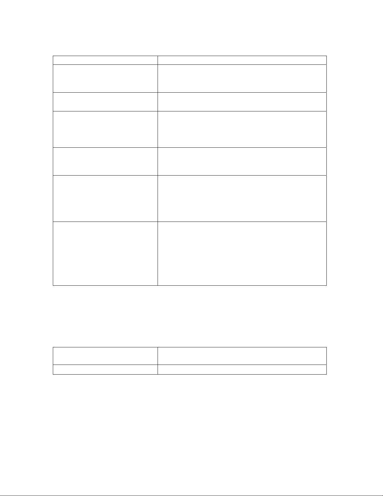
General Specifications
Basic Millennium II specifications are summarized in table 2-B. Consult service center
for other details.
Table 2-B: General Millennium II Controller Specifications
General Specifications
Input Voltage Range ±24 Vdc, -48 Vdc (Range: 18-60V)
Maximum Input Power 36W depending upon options
Operating Temperature Range -40 to 75 °C (-40 to 167 °F)
Storage Temperature Range -40 to 85 °C (-40 to 185 °F)
Physical Specifications 9.24 in. H, 20.76 in. W, 2.14 in. D
Display 8-line by 40-character backlit LCD
Cabinet Mounting Requirements Door mounted
Input/Outputs Specifications
Form C Alarm Output Contact Ratings 60VDC at 0.5A
Plant Voltage Measurement
Accuracy
0 to 50 °C (±.05% of full scale + 1
count)
-40 to 85 °C (±0.1% of full scale + 1
count)
Resolution
Plant Current Measurement (Up to 2
shunts)
Accuracy
Resolution
Temperature Measurement
Accuracy
Thermistor temperature
One-Wire Serial probes
Resolution
4-20mA Input Monitor
Accuracy
Resolution
General (0-5V) Input
Accuracy
48V Systems: ±40 mV
24V Systems: ±25 mV
48V Systems: ±70 mV
24V Systems: ±40 mV
0.01V
0 to +50 °C : ±0.5% of full scale
-40 to +85 °C: ±1.25% of full scale
1A
-5 to +55 °C: ±2°C
-40 to +85 °C: ±3°C
-5 to +55 °C: ±1°C (next release)
-40 to +85 °C: ±3°C
0.1°C
±100µA
±10.0µA
0 to +50 °C: ±0.5% of full scale
Issue 3 January 2008
11
Page 12
Basic Installation and User’s Guide for the Millennium II Controller
Resolution
Safety And Standards Specifications
Electrostatic Discharge IEC 801-2 level 2, 4, 5
Radiated Emissions FCC Class B, CISPR 22 level B
Safety UL Unlisted Component as Part of GPS Power
NEBs Level 3 Tested and Complaint with Galaxy Power
It should also be noted that the Millennium II is suitable for use in power plants with or
without batteries. In batteryless plants, the loss of ac power causes an immediate loss of
dc power to the controller and the activation of all office alarm relays. When ac power is
restored, plant rectifiers will return to their last specified voltage set point, and the
controller will automatically return to its last configuration.
-40 to +85 °C: ±1.0% of full scale
0.01VDC
System
Systems
Hardware
Chassis
The Galaxy Millennium II, like its Millennium predecessor, is low-profile enclosure
mounted on the inside front cabinet door of a Galaxy Power System (GPS) plant. See
Figure 2-1, and 2-2. This arrangement occupies no space within the frame mounting
racks, thus allowing additional room for other plant equipment. The unit is pre-installed
in the factory for all applicable GPS configurations. However, it has been designed to be
backwards compatible to existing Millennium to allow field replacements or upgrades. It
is composed of two main components: a rust resistant metal enclosure and a clear plastic
cover. The metal enclosure interfaces with the cabinet door and provides appropriate
cable routing entrances to the circuit pack it secures. A maintenance friendly clear plastic
cover is used to protect the enclosed circuit packs. This cover also provides clear and
quick visibility to individual circuit pack alarm status indicators and all wiring
connections without removing a cover allowing quick board integrity and connectivity
checks without removing cover.
Issue 3 January 2008
12
Page 13
Basic Installation and User’s Guide for the Millennium II Controller
Figure 2-1: Controller Dimensions
Figure 2-2: Millennium Mounted on Cabinet Door
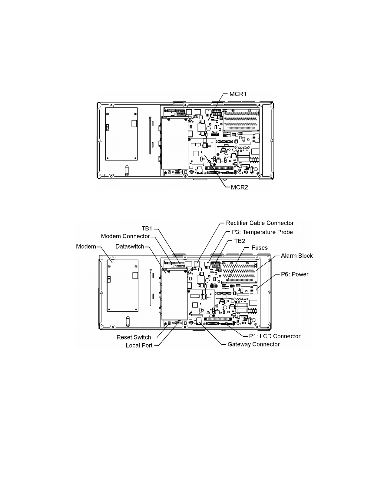
Controller Circuit Packs
MCR1 and MCR2
The core of the Galaxy Millennium II controller consists of a matched pair of surface
mount technology circuit packs, MCR1 and MCR2. These circuit cards are attached and
secured together at the factory. See Figure 2-3. The MCR1 is the larger of the two boards
and contains all the external input/output interfaces, local and remote user interface
circuitry, measurement circuits, real time clock, wide input range power converter, and
connections for the MCR2. The MCR2 contains the main 32-Bit 66MHz microprocessor
Issue 3 January 2008
13
Page 14
Basic Installation and User’s Guide for the Millennium II Controller
with 16Mbytes of Flash memory and 8Mbytes of RAM. It also contains the hardware for
the Ethernet control. Factory calibration values for the analog circuits located on the
MCR1 are stored in memory on the MCR2.
Figure 2-3: MCR1 and MCR2 Boards
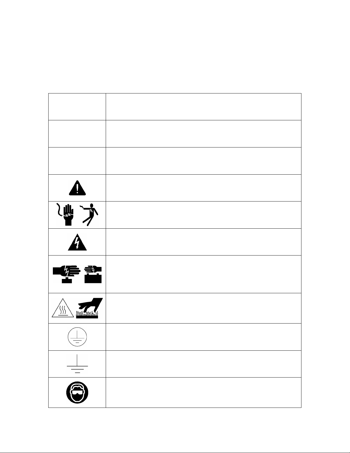
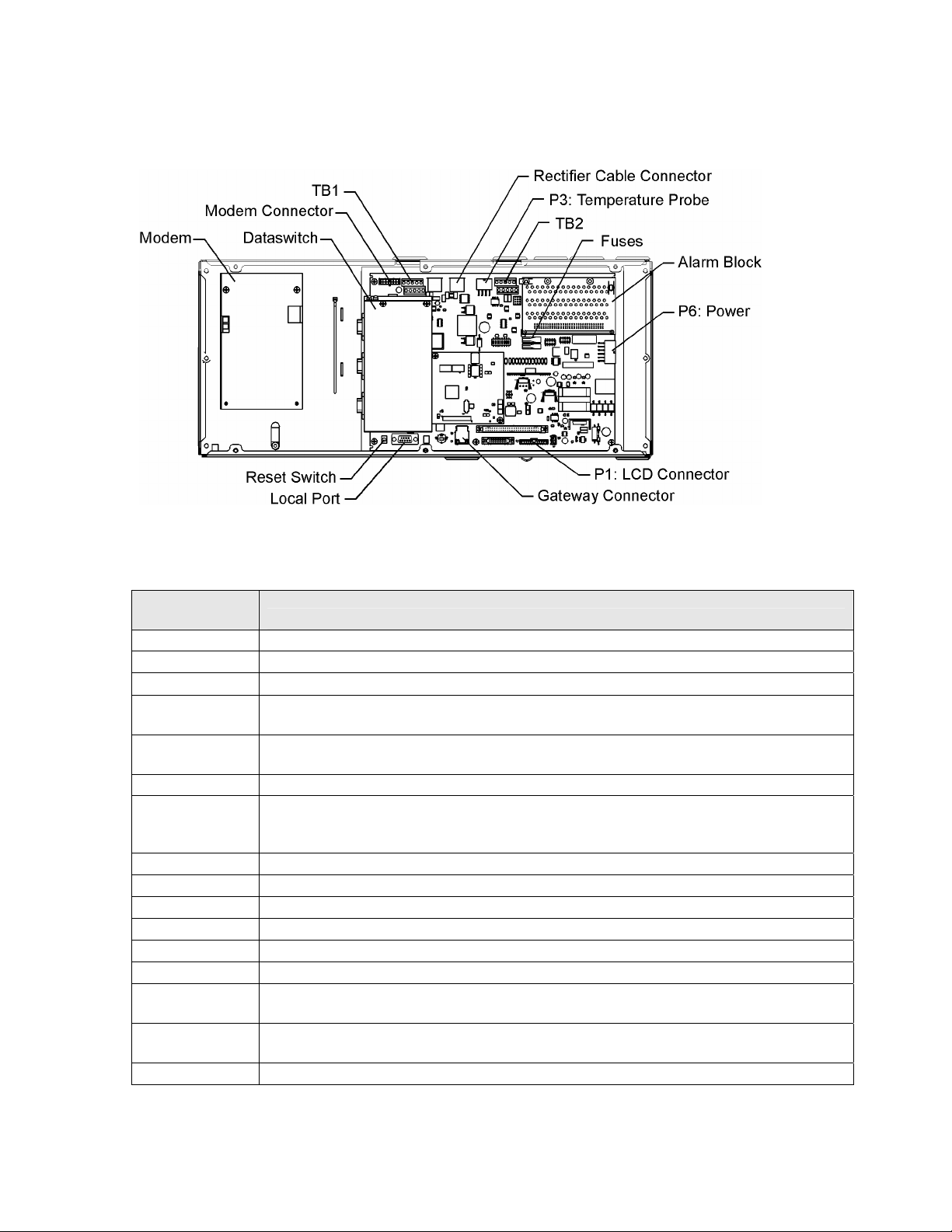
Figure 2-4: Millennium II Primary Interfaces
Figure 2-4 illustrates all of the primary interfaces located on the MCR1 for the
Millennium II controller.
Issue 3 January 2008
14
Page 15

Basic Installation and User’s Guide for the Millennium II Controller
3 Safety
Safety Statements
Please read and follow all safety instructions and warnings before installing, maintaining,
or repairing the Millennium II controller:
• The CE Mark demonstrates compliance with the European Union Council
Directives for Low Voltage and EMC.
• The Millennium II platform is Underwriters Laboratories (UL) recognized per
Subject Letter 1801, DC Power Distribution Centers for Telecommunications
Equipment.
• Install only in restricted access areas (dedicated equipment rooms, equipment
closets, or the like) in accordance with articles 110-16, 110-17, and 110-18 of the
U.S. National Electric Code (NEC), ANSI/NFPA No. 70, and pursuant to
applicable local codes.
• This equipment is to be used in controlled environments (an area where the
humidity is maintained at levels that cannot cause condensation on the equipment,
the contaminating dust is controlled, and the steady-state ambient temperature is
within the range specified).
• This equipment has been evaluated for continuous use in ambient temperature from
-40°C to 75°C.
• This equipment must not be installed over combustible surfaces.
• For installations in the United States, Listed compression connectors are to be used
to terminate Listed field-wired conductors where required. For all installations,
the appropriate connector is to be applied only to the correct size conductor as
specified by the connector manufacturer, using only the connector manufacturer’s
recommended tooling or tooling approved for that connector.
• If the proper connector for the country of installation is not provided, obtain
appropriate connectors and follow manufacturer’s and all local requirements for
proper connections. All national and local rules and regulations should be followed
when making field connections.
• All input and output connections comply with SELV requirements.
• Insulation on field-wired conductors should be rated no less than 90° Celsius. Wire
conductor size should be sized per electrical codes for 90° Celsius wire, and based
on the ampacity of the associated protection device. Wiring internal to enclosed
equipment cabinets should be rated at 105° Celsius (minimum).
Issue 3 January 2008
15
Page 16

Basic Installation and User’s Guide for the Millennium II Controller
• Torque or secure electrical connections to the values specified on labels or in the
product documentation.
• Alarm contacts on the office alarm connector are not fused within the controller;
therefore, current limiting protection for these contacts must be provided by
external circuits. Maximum ratings for alarm connections are 60Vdc and 0.5
amperes. Exceeding these maximum ratings could result in fire or damage to the
unit.
• In enclosed equipment cabinets, the Millennium II mounting framework must be
connected directly to the cabinet ac service ground bus. For applications in huts,
vaults, and central offices, the Millennium II mounting framework must be
connected to the system integrated ground grid.
• Installing fuses not specified for use in controller may result in equipment damage.
Use only replacement parts listed in this manual and on the equipment drawings.
• The telecom-type (e.g., GMT type) fuses can produce sparks during interruption or
clearing of a fault on a high energy circuit. Use only fuses provided with safety
caps for this type of circuit. Installing telecom-type fuses not equipped with safety
caps may result in injury to service personnel.
Issue 3 January 2008
16
Page 17
Basic Installation and User’s Guide for the Millennium II Controller
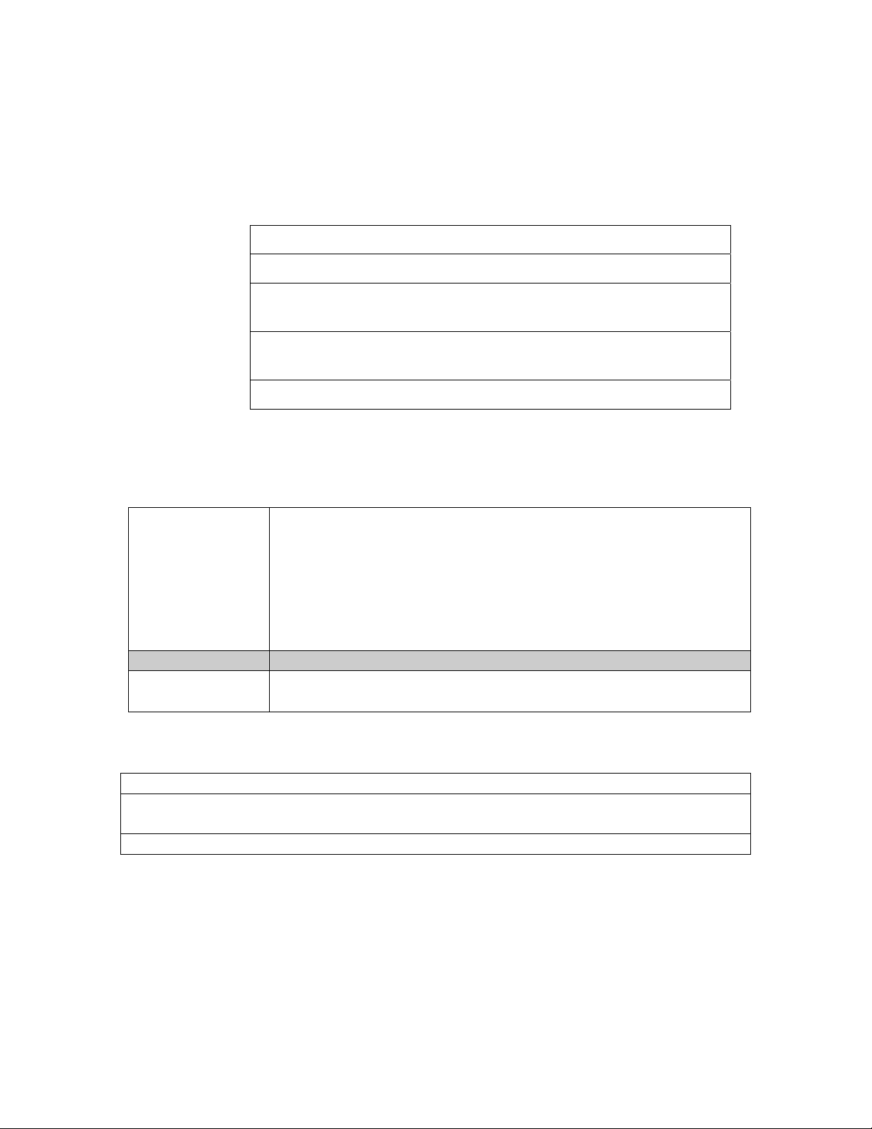
Warning Statements and Safety Symbols
The symbols may sometimes be accompanied by some type of statement; e.g.,
“Hazardous voltage/energy inside, or Risk of injury. This unit must be accessed only by
qualified personnel.” Signal words as described below may also be used to indicate the
level of hazard.
Indicates the presence of a hazard that will cause death or severe personal
DANGER
WARNING
CAUTION
injury if the hazard is not avoided.
Indicates the presence of a hazard that can cause death or severe personal
injury if the hazard is not avoided.
Indicates the presence of a hazard that will or can cause minor personal
injury or property damage if the hazard is not avoided.
This symbol identifies the need to refer to the equipment instructions for
important information.
These symbols (or equivalent) are used to identify the presence of
hazardous ac mains voltage.
This symbol is used to identify the presence of hazardous ac or dc
voltages. It may also be used to warn of hazardous energy levels.
One of these two symbols (or equivalent) may be used to identify the
presence of rectifier and battery voltages. The symbol may sometimes be
accompanied by some type of statement, for example: “Battery voltage
present. Risk of injury due to high current. Avoid contacting conductors
with uninsulated metal objects. Follow safety precautions.”
One of these two symbols may be used to identify the presence of a hot
surface. It may also be accompanied by a statement explaining the hazard.
A symbol like this with a lightning bolt through the hand also means that
the part is or could be at hazardous voltage levels.
This symbol is used to identify the protective safety earth ground for the
equipment.
This symbol is used to identify other bonding points within the equipment.
Issue 3 January 2008
This symbol is used to identify the need for safety glasses and may
sometimes be accompanied by some type of statement, for example:
“Fuses can cause arcing and sparks. Risk of eye injury. Always wear
safety glasses.”
17
Page 18

Basic Installation and User’s Guide for the Millennium II Controller
Precautions
When working on or using this type of equipment, the following precautions should be
noted:
• This unit must be installed, serviced, and operated only by skilled and qualified
personnel who have the necessary knowledge and practical experience with
electrical equipment and who understand the hazards that can arise when working
on this type of equipment.
• The equipment could be powered by multiple ac inputs. Ensure that the appropriate
circuit protection device for each ac input being serviced is disconnected before
servicing the equipment. Do not disconnect permanent bonding provisions unless
all ac inputs are disconnected.
• Batteries may be connected in parallel with the output of the rectifiers. Turning off
the rectifiers will not necessarily remove power from the bus. Make sure the battery
power is also disconnected and/or follow safety procedures while working on any
equipment that contains hazardous energy/voltage.
• Hazardous energy and voltages are present in the unit and on the interface cables
that can shock or cause serious injury. Follow all safety warnings and practices
when servicing this equipment. When equipped with ringer modules, hazardous
voltages will be present on the ringer output connectors.
In addition to proper job training and safety procedures, the following are some basic
precautions that should always be used:
• Use only properly insulated tools.
• Remove all metallic objects (key chains, glasses, rings, watches, or other jewelry).
• Wear safety glasses. Fuses can produce sparks. High energy levels on buses and
distribution components can produce severe arcing.
• Test circuits before touching.
• Lock out and tag circuit breakers/fuses when possible to prevent accidental turn on.
• Be aware of potential hazards before servicing equipment.
• Identify exposed hazardous electrical potentials on connectors, wiring, etc. (note the
condition of these circuits, especially wiring).
• Use care when removing or replacing covers; avoid contacting circuits.
Issue 3 January 2008
18
Page 19

Basic Installation and User’s Guide for the Millennium II Controller
Special Installation Notes
Deutsch
Installationsanleitung
Eingangsspannung ( Voltage ) : 2x AC 120/200-240V V
Eingangsstrom ( Current ) : QS801A, max 45A, QS800A, max 30A
Eingangsleistung ( Watts ) :
Nennfrequenz ( Frequency ) : 50 / 60 Hz
Seriennummer ( Assembly No. ):--
Modellnummer (Modell No. ) : QS801A, QS 800A
Abmessungen sind nur zur Referenz : 150mm x 22.5mm x 77.5mm
( Dimensions are for reference only )
Max. Umgebungstemperatur : max. 75 deg. C
( Max. Operation temperatur )
Achtung: Für kontinuierlichen Feuerschutz sollte die Sicherung nur mit einer des
gleichen Types ersetzt werden.
Sicherungswert :
( Warning : For continued protection against fire replace with same type and
rating of fuse )
Das System ist ein Gerät der Schutzklasse I / Überspannungs Kategorie II
( Power Supply is a Class I equipment / overvlotage category II )
Ausgangsspannungen und –stöme: DC 58 V / SELV
( Output Voltage and Current )
--Das Gerät darf nur in Räumen mit beschränktem Zutritt aufgestellt werden.
( Nur ausgebildetes Personal )
--Nur für Aufstellung auf Boden oder einer anderen brennbaren Oberfläche
geeignet.
--Das Gerät hat keinen eigenen Ausschalter, es muß daher mit einem Ein- und
Ausschalter im Versorgungskreis versehen sein.
--Das Gerät ist für den Einbau in IT- Geräte in einem Rahmen bestimmt (siehe
weitere Anleitung)
--Beim Einbau des Gerätes ist daraf zu achten das alle Anforderungen gemäß
EN60950 eingehalten werden.
ACHTUNG: HOHER ABLEITSTROM
VOR ANSCHLUSS AN DEN VERSORGUNGSSTROMKREIS
UNBEDINGT ERDUNGSVERBINDUNG HERSTELLEN
Issue 3 January 2008
19
Page 20

Basic Installation and User’s Guide for the Millennium II Controller
Espanol
Notas especiales para instalaciones en países de habla hispana
• Instrucciones de instalación
(Installation Instructions)
• Voltaje (Voltage):
Vea tabla 2-A
• Corriente (Current):
Vea tabla 2-A
• Frecuencia (Frequency):
50/60Hz
• Voltaje y corriente de salida (Output Voltage and Current):
Vea tabla 2-A
• Temperatura IREa de operación (Maximum Operation Temperature):
75°C (167°F)
• Sin cabina contra incendios, suelo no combustible
(No IRE enclosure, non-combustible floor)
• Evaluado en EN60950
(Evaluated to EN60950)
Issue 3 January 2008
20
Page 21
Basic Installation and User’s Guide for the Millennium II Controller
4 New Installations
The Millennium II is factory pre-installed and pre-configured with industry standard
defaults for thresholds and feature operability in GPS cabinet applications. In addition,
customer specific default controller settings may be available upon request. This section
provides:
Preparation and Precautions
Procedures for the proper addition of optional packs
Input and output wiring to the controller and the installation and
wiring of optional features
Controller default configuration information such as alarm severity
and description, system voltage, shunt information
Controller configuration information
Preparation
The following
Installation
procedures should
be performed
AFTER:
But BEFORE:
Precautions
Observe ESD protection while installing circuit packs.
Wear grounded antistatic wrist straps when handling all circuit packs. The wrist strap
must contact the skin and is not to be worn over clothing.
Never hand a circuit pack from a grounded to a non-grounded person or vice-versa.
• All the equipment frames (initial and supplemental bays, free-
standing rectifiers, etc.) are anchored in place.
• The battery stands have been erected and the batteries installed.
• The overhead cable racks have been installed and the power
cables have been run and terminated.
• The plant’s charge and discharge bus bar assemblies have been
installed.
• Connecting the batteries to the plant charge and discharge bus
bars or turning up the plant rectifiers.
Issue 3 January 2008
21
Page 22

Basic Installation and User’s Guide for the Millennium II Controller
Safety
Action Verified
Always consider personal safety before beginning any procedure. Review
the Safety section.
Be aware of the presence of unfused battery potential in the vicinity of
the controller.
Use only insulated tools.
Make sure the system is properly grounded per the National Electrical
Code and local building codes.
Remove all metal jewelry before beginning the installation.
Installation Materials
Item Verified
Wire cutters and strippers
18 to 22 AWG wire
Jewelers screwdriver (Flat and Phillips)
Small needle nose pliers
Digital meter, +/- 0.02%
Screw Drivers (flat-blade and Phillips)
ESD wrist strap
Wire-wrap tool or Amp alarm punch-down tool
Issue 3 January 2008
Figure 4-1: Millennium II
22
Page 23
Basic Installation and User’s Guide for the Millennium II Controller
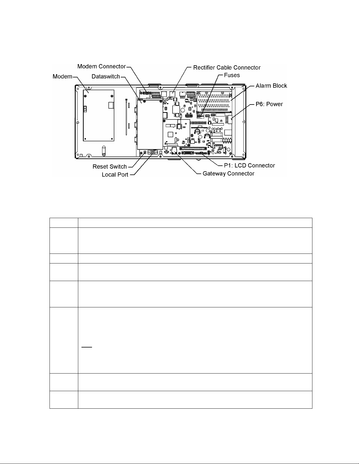
Controller Connections
Figure 4-2: Millennium II Controller Connections
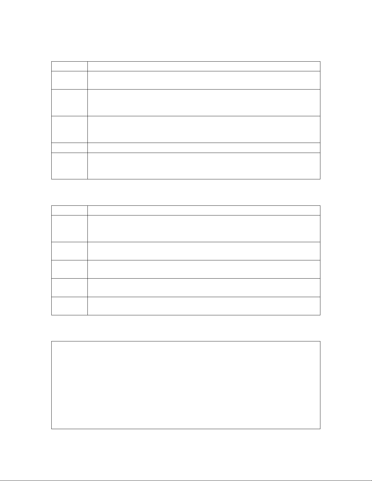
Table 4-A: Millennium II Interface Reference
Interface
Reference Description
P1
P2
P3
P6
P7
P8
P9
P13
P14
P15
P201
P202
P205
TB1
TB2
J10
Connectorized interface for large parallel format 8x40 LCD assembly
10/100 Base-T LAN/Ethernet interface
Connectorized interface for 10K/30K thermistor probe options or 210E
Connectorized input for input power, monitoring of two shunts, plant sense voltage, and
Major Fuse alarm (Same connection as on the Millennium)
RJ45 receptacle for ground referenced Auxiliary RS485 circuit and One-Wire temperature
monitoring devices
BSL1-4 circuit pack Interface connector for Input/Output to controller
RJ45 receptacle for isolated RS485 system component monitoring and control of rectifiers,
converters, low voltage disconnect contactors, and bay level alarm inputs (Serial Rectifier
bus)
Factory test connector (not used in the field)
Connectorized interface for future smaller serial format LCD
Connectorized interface for future smaller serial format LCD
Connectorized interface for optional Modem
Ground referenced DB-9 for local RS232 serial port
Option board connector
Terminal block interface for RS232/RS485 Auxiliary port and Remote Peripheral Module
(RPM) connections
Terminal block interface for three additional 10K thermistor probe or 210E connection
options
USB interface (reserved for future use)
Issue 3 January 2008
23
Page 24
Basic Installation and User’s Guide for the Millennium II Controller
Installing Circuit Packs
Figure 4-3: Millennium II Controller Connections
Modem Card
The optional Modem card may require field installation. To do so, perform the following
steps:
Step Action
NOTE:
1. Remove the controller front cover.
2. Install the BSM on the 4 standoffs, to left of the controller MCR1 board using
3. Connect the 848091798 cable assembly between the BSM J100 plug and P201
4.
5. Operate the reset switch on the MCR1 board in the lower left corner of the
NOTE:
Installation or replacement of this pack can be done “hot”; power removal is not
necessary.
four 845143866 screws.
on the MCR1 board.
Note: This step may be performed at a later time
Install phone line wiring from Connect the existing telephone cable to the RJ11
connector at the top of the board
OR
Connect Tip/Ring conductors to TB1 at the top of the board.
NOTE: Tip is TB1 pin 1 (Pin closest to the RJ11 connector) and Ring is Pin 3.
Pin 2 is not used.
MCR1 board. (see Figure 4-3)
The Password Reset button is to the LEFT of the serial port connector, and the
Controller Reset is to the right of the serial connector.
Issue 3 January 2008
24
Page 25

Basic Installation and User’s Guide for the Millennium II Controller
Data Switch Card
Step Action
NOTE:
Installation or replacement of this pack can be done “hot”; power removal is
not necessary.
2. Install two 407882133 standoffs on the BSJ intelligent board. Screw threads
are protruding just below TB1, located at the upper left hand corner of the
MCR1 board.
3. Place BSW pack inside the 847950938 insulator.
4. Plug BSW pack into the P205 connector on the BSJ intelligent controller
board
5. Secure the BSW board to the standoffs with two 900562208 screws.
NOTE:
To install the Data Switch Extension board, please see the User’s Guide for
Millennium II Controller Advanced Features manual.
Alarm Termination Board
Alarm Termination board options provide for wire wrapped or insulation displacement
(punch down) terminations. The Alarm Termination Board for a specific application may
require field installation. To do so, perform the following steps:
Step Action
1. In the upper right hand corner of the MCR1 board, find the alarm board
already installed.
2. Remove the two screws holding the board at the top.
3. Holding the board on both sides, slowly, but firmly, remove the alarm board
from the P8 connector.
4. Unpack the new board from its box, carefully observing proper ESD
procedures.
5. Connect the alarm board to P8 and press down firmly, until the board is
seated.
6. Secure the alarm board at the top using the two screws removed earlier.
Issue 3 January 2008
25
Page 26
Basic Installation and User’s Guide for the Millennium II Controller
Gateway (LAN) Connections
Step Action
NOTE:
The Gateway card has been designed into the MCR1/MCR2 boards and
requires no additional circuit packs.
NOTE:
The Gateway has an IEEE 802.3 compliant 10Base-T network interface.
Since the cable length required to connect to the network is variable, this
cable must be supplied by the user.
1. At the controller, connect one end of the network interface cable to P2. This
connector is located at the bottom center of the MCR1 board, and
immediately below the MCR2 board.
2. Connect the other end to an IEEE 802.3 compatible network.
3. Configure the Gateway for the network by contacting the customer’s
network administrator. Detailed configuration information may be found in
the User’s Guide for Millennium II Controller Advanced Features manual.
Rectifier Cabling
Step Action
NOTE:
For new installations, the Millennium II rectifier cabling has been factory
wired and installed to the cabinet BIC/BLJ board for alarm and rectifier
communication.
NOTE:
For connector integrity, verify that the cable is installed and connected
properly.
1. Verify that the rectifier cable is connected to P9, and NOT P7(AUX) cable
connector.
2. Verify that the cable connector is properly seated into P9, and that it is not
loose.
3. Verify that the rectifier cable terminating on the BIC/BLJ board is connected
to P9 and also not loose.
Remote Peripheral Monitoring (RPM)
RPM provides data acquisition capability far beyond that normally available in a power
system controller. Monitoring modules available consist of:
• Shunt monitors (6 channels + 1 temperature channel)
• 0-100mV dc Voltage monitors (6 channels + 1 temperature channel)
• 0-3V dc Voltage monitors (6 channels + 1 temperature channel)
• 0-16V dc Voltage monitors (6 channels + 1 temperature channel)
• 0-200V dc Voltage monitors (6 channels + 1 temperature channel)
• Temperature monitor (7 Channels)
• Control Relay module (3 sets of programmable form C relay outputs)
Issue 3 January 2008
26
Page 27

Basic Installation and User’s Guide for the Millennium II Controller
The user may connect a maximum of 95 of any combination of these modules serially.
Step Action
NOTE:
The Remote Peripheral Monitoring feature has been designed into the MCR1
board and requires no additional circuit packs. Monitoring and control
modules ARE required, based on the application.
NOTE:
This section only describes a single module connection to the controller.
Modules MUST BE PROGRAMMED after they have been installed or they
may not function properly. Detailed connection and configuration
information may be found in the User’s Guide for Millennium II Controller
Advanced Features manual.
1. Using the RPM bus cable (comcode 407377704), wrap the cable through the
EMI inductor bead twice. Place the bead approximately 3 inches from the
end of the cable.
2. Connect the bus cable to:
TB-1 Pin
Assignments
TB-1 Pin
Descriptions
RPM
Conductor
RPM Conductor
Description
Color
6 *6 Blue or White Power/Communications
8 *8 Blue or White Power/Communications
9 or 10 FGND Bare wire Shield
*connections of the bus wire are NOT polarity sensitive.
3. Secure the module connection unit and route the wires through the openfaced bottom of the connection unit.
4. Make the connections to TB2 on the connection unit:
TB-2 Pin
Assignments
RPM
Conductor
RPM Conductor
Description
Color
IN Blue or White Power/Communications
OUT Blue or White Power/Communications
SHIELD Bare wire Shield
*connections of the bus wire are NOT polarity sensitive.
* there are 2 IN, and 2 OUT connections. Either one may be used.
5. Locate the control unit. This is the half with circuitry on it.
6. In the lower right hand side of the control unit (inside), are two rotary
switches. Set SW-1 (LO) to 1. The module will be recognized as 01 by the
controller. Other modules added cannot have the same address or 00 for the
address.
7. Carefully attach the control unit to the connection unit using the ribbon
connector.
Issue 3 January 2008
27
Page 28
Basic Installation and User’s Guide for the Millennium II Controller
NOTE:
8. After approximately 1 minute, the green LED on the front of the module will
This connector/cable is not keyed, so be careful to line up the pins properly.
blink once approximately every 5 seconds. Detailed troubleshooting
information may be found in the User’s Guide for Millennium II Controller
Advanced Features manual.
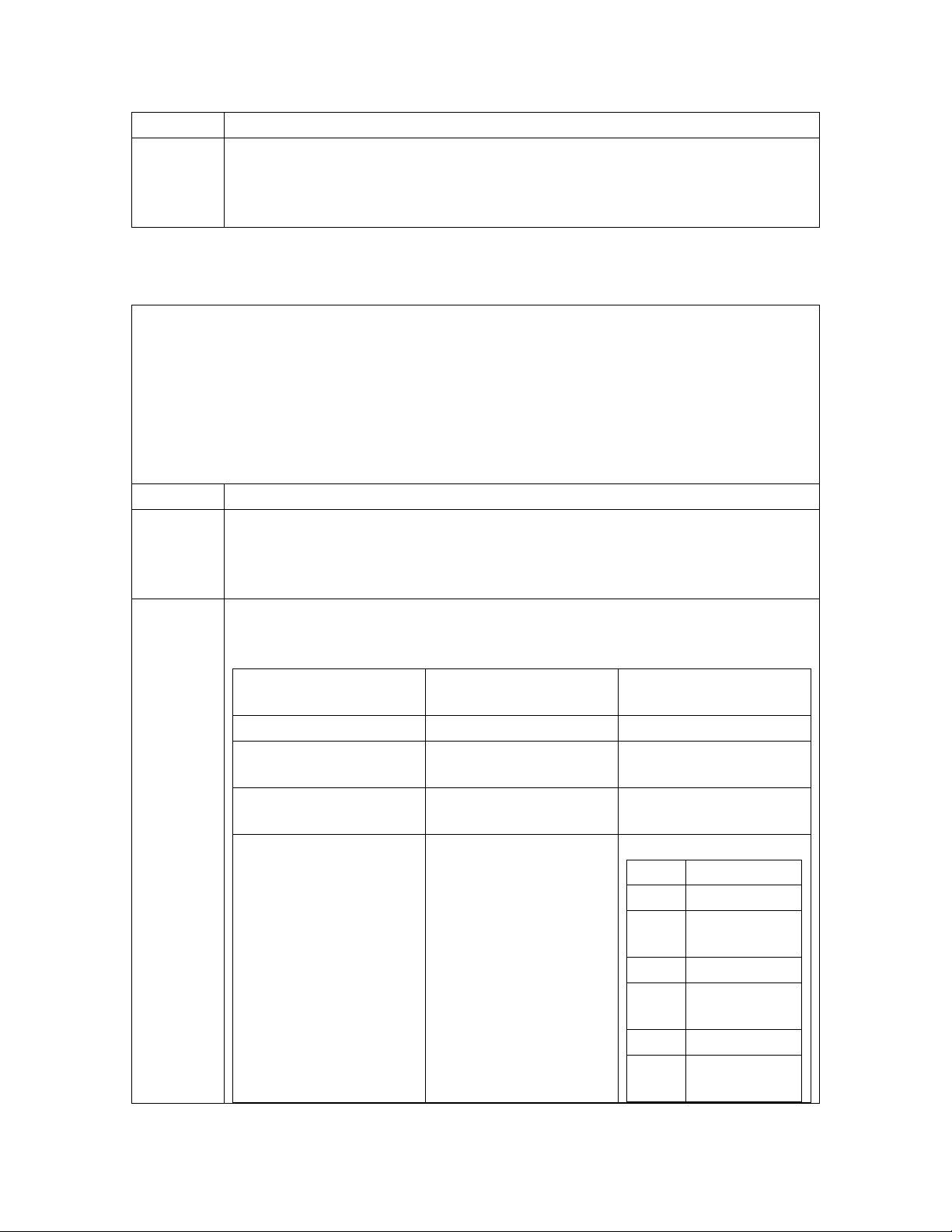
Thermal Probes
Without thermal probes, many of the controller’s battery management features will not
function, or produce erroneous results. Some features requiring thermal inputs are:
• Slope Thermal Compensation
• Reserve Time Prediction
• High Temperature Alarm
• Ambient High and Low Temperature Alarms
• High Temperature Disconnect
Step Action
NOTE:
1. The following table shows the type of probe and connector location on the
The controller supports a number of thermal probe inputs. The type of probe
used determines where it is connected on the controller. Detailed thermal
probe and battery management information may be found in the User’s
Guide for Millennium II Controller Advanced Features manual.
Millennium:
Type of Probe Comcode Controller Connection
Location
10/30K P3
210E Thermal Probe
Mux
1 Wire Temperature
Monitoring Devices
Terminal Block
Interface for 3
additional 10k probes
or 210E connection
P3
P7
TB2
Pin Description
1 Probe 2
2 Probe 2
RTN
3 Probe 3
4 Probe 3
RTN
5 Probe 4
6 Probe 4
RTN
Issue 3 January 2008
28
Page 29
Basic Installation and User’s Guide for the Millennium II Controller
USB Interface
This interface is reserved for future use.
Wiring Alarm Outputs
These external alarms may be wired to customer external office alarms at their
destination.
Form-C Alarm Contact Ratings 60Vdc, 0.3A
Conductor Size for terminating on Alarm
board
Refer to Table 4-B and 4-C for lead designations and their descriptions for leads
terminating on the BSL alarm interface board.
Table 4-B: Controller Alarm Descriptions and Pin Numbers
Pin
Number
1 PCRAO 33 MJFR 65 FAN
2 PCRAC 34 MNFR 66 AMN
3 PCRAR 35 MNFC 67 TFLT
4 PCRVR 36 MNFO 68 TBST
5 PCRVC 37 BDO 69 TRTN
6 PCRVO 38 BDC 70
7 PCREO 39 BDR 71
8 PCREC 40 ACFR 72 OS
9 PCRER 41 ACFC 73 TR1
10 PMJAR 42 ACFO 74 TEQ
11 PMJAC 43 RFAO 75 ETR
12 PMJAO 44 RFAC 76 ETRR
13 PMJEO 45 RFAR 77 RO
14 PMJEC 46 HVR 78 ROR
15 PMJER 47 HVC 79 TR2
16 PMJVR 48 HVO 80 TR4
17 PMJVC 49 UR1O 81
18 PMJVO 50 UR1C 82 TBD
Signal
Name
Pin
Number
18 – 22AWG (if less than 18AWG, use
multi-conductor cable for mechanical
integrity)
Signal
Name
Pin
Number
Signal Name
PBTR
PBT
RBRPO
now general
I/O-1
Issue 3 January 2008
29
Page 30
Basic Installation and User’s Guide for the Millennium II Controller
Pin
Number
19 PMNAO 51 UR1R 83 USR1PRESENT/
20 PMNAC 52 CTLRR 84 LVD1
21 PMNAR 53 CTLRC 85 TR3
22 PMNVR 54 CTLRO 86
23 PMNVC 55 UR2O 87
24 PMNVO 56 UR2C 88
25
26 - 58 UR3R
27 - 59 UR3C
28 PMNER 60 UR3O
29 PMNEC 61 LVD2 93 ABS
30 PMNEO 62 LVD2R 94 ABS
31 MJFO 63 FAJ 95 DG
32 MJFC 64 AMJ 96 DG
Critical-Audio
Critical-Visual
Critical-External
Power Major-Audio
Power Major –External
Power Major –Visual
Signal
Name
5V
Pin
Number
Signal
Name
Pin
Number
Signal Name
BTP
now general
I/O-2
-
4-20mA in
4-20mA Rtn
57 UR2R 89 USR3PRESETN/
BTPFLT
now general I/O-
3
90 USR3DETECT/
Now VLVR
91
BTMJ
0-5V in
Now VLVC
92
0-5V Rtn
Now VLVO
1 PCRAO
2 PCRAC
3 PCRAR
4 PCRVR
5 PCRVC
6 PCRVO
7 PCREO
8 PCREC
9 PCRER
10 PMJAR
11 PMJAC
12 PMJAO
13 PMJEO
14 PMJEC
15 PMJER
16 PMJVR
17 PMJVC
18 PMJVO
Issue 3 January 2008
30
Page 31

Basic Installation and User’s Guide for the Millennium II Controller
Power Minor-Audio
Power Minor –Visual
Power Minor –External
Major Fuse
Minor Fuse
Battery On Discharge
AC Fail
Rectifier Fail
High Voltage
User Relay 1
Controller Fail
User Relay 2
Very Low Voltage
19 PMNAO
20 PMNAC
21 PMNAR
22 PMNVR
23 PMNVC
24 PMNVO
28 PMNER
29 PMNEC
30 PMNEO
31 MJFO
32 MJFC
33 MJFR
34 MNFR
35 MNFC
36 MNFO
37 BDO
38 BDC
39 BDR
40 ACFR
41 ACFC
42 ACFO
43 RFAO
44 RFAC
45 RFAR
46 HVR
47 HVC
48 HVO
49 UR1O
50 UR1C
51 UR1R
52 CTLRR
53 CTLRC
54 CTLRO
55 UR2O
56 UR2C
57 UR2R
58 VLVR
59 VLVC
60 VLVO
Issue 3 January 2008
31
Page 32

Basic Installation and User’s Guide for the Millennium II Controller
Wiring Alarm and Control Inputs
In a standard Galaxy Power System configuration, plant level alarms are sent to the
controller via the Bay Interface Card through serial data communication. The following
alarm inputs are provided for discretionary use in non-standard applications.
Table 4-C: Controller Alarm and Control Inputs
Alarm Pin
Number
Low Voltage 2 Disconnect State Detect 61 LVD2
Fuse Alarm Major 63 FAJ
Fuse Alarm Minor 65 FAN
Auxiliary Alarm Major 64 AMJ
Auxiliary Alarm Minor 66 AMN
Timer Float Control 67 TFLT
Timer Boost Control 68 TBST
Plant Battery Test 71 PBT
Open String Detect 72 OS
Transfer Rectifier 1 73 TR1
General Purpose Input 4 74 IN-4 previously TEQ
General Purpose Input -5 (Previously
Engine Transfer)
Reserve Operation 77 RO
Transfer Rectifier 2 79 TR2
Transfer Rectifier 4 80 TR4
Reserve Battery-Emergency Power Off 81 RBRPO
General Purpose Input 1 82 IN-1
BTP or General Purpose Input 2 83 IN-2/BTP
Low Voltage 1 Disconnect State Detect 84 LVD1
Transfer Rectifier 3 85 TR3
General Purpose 4-20mA Measuring
Circuit
General Purpose 4-20mA Measuring
Circuit-RTN
BTPFLT or Generic Input 3 89 IN-3/ BTPFLT
Low Voltage 3 Disconnect State Detect
Also
Battery Thermal Protect Major
General Purpose 0-5Vdc Measuring
Circuit
General Purpose 0-5Vdc Measuring
Circuit-RTN
75 IN-5 Previously ETR
87 4-20mA
88 4-20mAR
90 LVD3/ BTMJ
91 0-5V
92 0-5VR
Signal Name
Issue 3 January 2008
32
Page 33

Basic Installation and User’s Guide for the Millennium II Controller
BSL-63 FAJ: Fuse Alarm Major
An optional battery potential input, must use an external 1K ohm 2W current limiting
resistor at the source. A Fuse Alarm Major is generated when battery potential is
received.
BSL-65 FAN: Fuse Alarm Minor
A battery potential input is required, which must use an external 1K ohm, 2W current
limiting resistor at the source. A Fuse Alarm Minor is generated when battery potential is
received.
BSL-72 OS: Open String Alarm
A battery potential input is required, which must use an external 1K ohm 2W current
limiting resistor at the source. This circuit is used to signal Galaxy that a battery string
protective device or switch is in the open position. An Open String Alarm is generated
when battery potential is received.
BSL-64 AMJ: Aux Major
A battery potential input is required, which must use an external 1K ohm, 2W current
limiting resistor at the source. This circuit is used to allow Galaxy to monitor another
power device and provide alarms for it. An Aux Major Alarm is generated when battery
potential is received.
BSL-66 AMN: Aux Minor
A battery potential input is required, which must use an external 1K ohm, 2W current
limiting resistor at the source. This circuit is used to allow Galaxy to monitor another
power device and provide alarms for it. An Aux Minor Alarm is generated when battery
potential is received.
LVD1: BSL-84 Low Voltage Disconnect Active
A battery potential input is required, which must use an external 1K ohm, 2W current
limiting resistor at the source if not using standard Lineage Power LVD circuit boards or
controller. This circuit is used to inform Galaxy that the monitoring circuit of a Low
Voltage Disconnect device has failed. In standard Galaxy Power Systems, the Bay
Interface board monitors these alarms and informs the Controller through the serial
interface connection.
LVD2/LVD2R: BSL-61/62 Low Voltage Disconnect Active
A closure between these points or a ground signal into LVD2/ BSL-61 is used to inform
Galaxy that the a Low Voltage Disconnect device has opened. In standard Galaxy Power
Systems, the Bay Interface board monitors these alarms and informs the Controller
through the serial interface connection.
External Boost Option
A variety of external devices may be used to initiate boost in Galaxy. Wiring is required
from positions 67/68/69 on the BSL board for operation of this feature. Providing a
contact closure between TBST and TRTN initiates the boost feature. A contact closure
between TFLT and TRTN returns the plant to float. Additional information on External
Boost can be found in the User’s Guide for Millennium II Controller Advanced Features
manual.
Issue 3 January 2008
33
Page 34

Basic Installation and User’s Guide for the Millennium II Controller
Rectifier Sequence Option
The controller is capable of sequencing rectifiers on line after detecting a AC is being
provided by emergency generator. Internal Rectifier Sequencing requires external wiring
to ETR/ETRR on BSL pin numbers 75/76, and optionally RO/ROR on BSL pin numbers
77/78, in order to function.
The controller can also accept ground signals onto TR1 to TR4 on BSL 73/79/ 85/80
from an external device to control the sequencing of plant rectifiers in groups as follows:
Table 4-D: TR leads and Associated Rectifiers
TR
Rectifiers Affected
Signal
TR1 G01, G02, G09, G10, G17, G18, G25, G26, G33, G34, G41, G42, G49, G50,
G57, G58
TR2 G03, G04, G11, G12, G19, G20, G27, G28, G35, G36, G43, G44, G51, G52,
G59, G60
TR3 G05, G06, G13, G14, G21, G22, G29, G30, G37, G38, G45, G46, G53, G54,
G61, G62
TR4 G07, G08, G15, G16, G23, G24, G31, G32, G39, G40, G47, G48, G55, G56,
G63, G64
Additional information on the Rectifier Sequence Options can be found in the User’s
Guide for Millennium II Controller Advanced Features manual.
Battery Temperature Option
Slope Thermal Compensation and Battery Reserve Time Prediction features of the
controller, require that battery temperature be monitored. If either of these features is to
be configured in Galaxy software, a battery temperature input must be connected to P3
temperature probe connector on the Controller board.
Three optional cables are used to connect to various battery arrangements:
Cable Assembly Connects to:
848152997 KS20472 round cell thermistor
848152989 ring or paddle type thermistors
848153003 210E Thermal Probe Multiplexer
Refer to User’s Guide for Millennium II Controller Advanced Features manual for
additional information on these features.
Alarm Battery Supply Signals
Table 4-E: ABS Pin Numbers
Signal
Pin No.
Name
ABS 93
ABS 94
DG 95
DG 96
Issue 3 January 2008
34
Page 35

Basic Installation and User’s Guide for the Millennium II Controller
Fused Battery Supply
BSL-93, 94 ABS: Alarm Battery Supply
This is an alternate plant voltage source for user alarm systems. This power is fused with
a 1-1/3 ampere ABS fuse.
BSL-95,96 DG: Discharge Ground
Plant ground/return source for user alarm systems.
Fuses
Two Fuses, located on the MCR1 board, provide protection for the controller input power
and Alarm Battery Supply, used to power alarm panels or other devices requiring the
power system voltage at no more than 1.3A.
Figure 4-4: Millennium Controller Fuses
FUSE Description Fuse Size
F1 Controller Input Power 3A
F2 Alarm Battery Supply
(ABS)
1.3A
Front Panel Display
LCD
The primary local interface for the Millennium II is an eight-line LCD assembly mounted
to the front of the primary GPS cabinet door. This user interface is a panel that includes a
backlit LCD module, two sections of status LEDs, system voltage test jacks, and an array
of simple push-button controls. This controller supports multiple LCD display
assemblies. It is backwards compatible to both existing Millennium LCD assemblies L51
and L50 shown in Figure 4-5. It is also compatible with the enhanced L52 LCD display
assembly (see figure 4-6) specifically developed for the Millennium II. This new display
Issue 3 January 2008
35
Page 36

Basic Installation and User’s Guide for the Millennium II Controller
assembly is compatible to existing GPS cabinet doors and is functionally backwards
compatible to the Millennium. It looks very similar to the L51 option. LCD assembly, but
the L52 also provides a built-in audible alarm and digital contrast adjust that are only
available when used with the Millennium II controller.
Figure 4-5: Controller Front Panel Displays
Figure 4-6: Detailed Controller Front Panel Display – L51/52
Issue 3 January 2008
36
Page 37

Basic Installation and User’s Guide for the Millennium II Controller
LEDs
Depending on the LCD option utilized, the LCD assemblies contain two rows of LEDs at
the right side of the interface board or two columns of LEDs at the left side of the
interface board as seen in figure 4-5. The segregated sections of LEDs provide an
indication of the alarm source (rectifier, battery, distribution, communication, controller,
remote modules) and the severity (Critical, Major, Minor, Nominal) of the various
alarms. Operation of the status LEDs can be reconfigured via the local or remote
controller interfaces.
Push Buttons
A group of push-button keys identified in table 4-F, provides the primary method of
locally interacting with the Galaxy Millennium II controller. These keys are used singly
or in combination to navigate through the menus and follow industry standard
functionality. Following is the general description of all the keys.
Table 4-F: Push-Button Key Functionality
Key Function
Up arrow Use to navigate the menu; press the key to move the
cursor up one line.
Down arrow Use to navigate the menu; press the key to move the
cursor down one line.
Left arrow Use to navigate the menu; press the key to move the
cursor left one field.
Right arrow Use to navigate the menu; press the key to move the
cursor right one field.
ADJUST Plus
Use to adjust (increase) the value of a field.
(+)
ADJUST Minus
Use to adjust (decrease) the value of a field.
(-)
MENU Press this key any time to bring the MAIN menu on
line.
HELP Press this key to display limited on-line help
information.
ENTER Use this key to save a value that has been changed, or
to select a menu item.
ESCAPE Use this key to abort a change, or to go back to the
immediate higher level menu.
Lamp Test
Use this key to test the display and LEDs
(L50 Only)
Issue 3 January 2008
37
Page 38

Basic Installation and User’s Guide for the Millennium II Controller
Test Jacks
The Millennium II LCD panel assemblies also provide test jacks to provide the ability of
using an external meter to monitor the Plant Voltage as seen in figure 4-7. Voltages to the
front panel test jacks are current limited and ESD protected. The controller measures this
voltage to regulate the system bus voltage as well as display it as the battery plant bus
voltage. The value of this voltage is used for many other controller related features.
Serial (PC) Port
A ground referenced RS-232 local port is provided at the front of the display to allow
easy connection to a personal computer or terminal using ANSI T1.317 object oriented
command language. Lineage Power’s EasyView is also available to provide a user friendly
system interface locally or remotely. See figure 4-6.
Alarm Buzzer
The audible alarm buzzer is located on the front panel display assembly. It can be
programmed from the front panel display to operate as follows:
Contrast Adjust
• For L50, L52 Displays:
Press the + or – keys and hold until the display changes it’s contrast
setting. Once the desired setting is reached, release the button.
• For L51 Displays:
Using a small flat head jeweler’s screwdriver, insert it into the small
opening at the top of the display assembly (above the UP arrow). Turn
clockwise or counter clockwise until the display contrast is set.
Issue 3 January 2008
• Disabled for ALL Alarms
• Audible on PCR
• Audible on PMJ
• Audible on PMN
38
Page 39

Basic Installation and User’s Guide for the Millennium II Controller
Controller Defaults
Dip Switch Settings
The Millennium has 8 dip switch positions (SW202) that may be changed. SW202 is
located on the MCR1 board, above the MCR2 board. (See figure 4-7)
Figure 4-7: Millennium II Controller Dip Switches
Table 4-G: Millennium II Controller Dip Switch Settings
Switch
Position
SW202-8 1 Front Panel Configuration ENABLED DISABLED
SW202-7 0 Modem/Aux/Local/Gateway/USB/
SW202-6 0 Enhanced Security Mode (See
SW202-5 1 Auxiliary Port Configuration RS-232 RS-485
SW202-4 1 Remote Rectifier in Standby ENABLED DISABLED
SW202-3 0 Boost Mode ENABLED DISABLED
SW202-2 1 Reserved for Future Use ENABLED DISABLED
SW202-1 1 Reserved for Future Use ENABLED DISABLED
Default Description Closed
(1)
ENABLED DISABLED
IRDA Port Setting Configuration
(Remote Access)
ENABLED DISABLED
table 4-H, for features affected
Open
(0)
Issue 3 January 2008
39
Page 40

Basic Installation and User’s Guide for the Millennium II Controller
Table 4-H: Enhanced Remote Security Features
The modem and auxiliary ports can be configured for full access and read-only using DIP
switch 202-7. Restricted access is also available. This prevents changes ia the modem and
auxiliary ports that will affect the state of the plant, even when logged in as a Super-User
or Administrator. This enhanced remote security is enabled and disabled with DIP switch
SW202-6. The functions and parameters restricted with the enhanced remote security
feature are listed in this table.
Enable or disable Rectifier Restart feature
Change All Rectifier On Threshold
Change Timed Manual Boost Duration
Change Boost Current Threshold
Change Rectifier Status to “Standby”/ “Vacant” status is prohibited. The change to
“On”status is allowed.
Change Rectifier Shunt Voltage configuration
Change Rectifier Float High Voltage Shutdown Threshold
Change Rectifier Boost High Voltage Shutdown Threshold
Change Rectifier Float Set Point
Change Rectifier Boost Set Point
Change Rectifier Boost Current Limit
Change Converter Voltage Set-Point
Change Converter Low Voltage Disconnect Threshold
Change Converter Low Voltage Reconnect Threshold
Enable or disable Converter Low Voltage Disconnect feature
Change Converter Status to “Standby”/ “Vacant” status is prohibited. The change to
“On”status is allowed.
Change Battery High Temperature Threshold
Enable or disable Battery Current Limit
Change Battery Limit Threshold
Change Battery Contactor Status to “Open” status is prohibited. The change to “Close”
status is allowed.
Change Battery Disconnect Threshold
Change Battery Reconnect Threshold
Change Very Low Voltage Alarm Threshold and Severity
Change Multiple Rectifier Fail Alarm Threshold and Severity
Change Limited Recharge Current Alarm Threshold and Severity
Change Excess Rectifier Drain Alarm Threshold and Severity
Change Engine Transfer Timeout Alarm Threshold and Severity
Change Reserve Time Low Alarm Threshold and Severity
Change Multiple Converter Fail Alarm Threshold and Severity
Change Battery On Discharge Alarm Threshold and Severity
Issue 3 January 2008
40
Page 41

Basic Installation and User’s Guide for the Millennium II Controller
Voltage Threshold Ranges and Default Values
Table 4-I: Voltage Threshold Ranges and Default Values
Low High Default
Very Low Voltage (VLV)
24V 20.00 25.50 23.00
48V 40.00 51.00 46.00
Battery on Discharge (BD)
24V Float 23.00 28.00 25.00
24V Boost 23.00 28.00 25.00
48V Float 46.00 55.00 51.00
48V Boost 46.00 55.00 51.00
High Float Voltage (HFV)
24V Float 24.75 29.75 26.50
24V Boost 25.75 31.75 26.50
48V Float 50.00 60.00 53.00
48V Boost 52.00 60.00 53.00
High Voltage Shutdown Alarm (HV)
24V Float 24.75 29.75 26.8
24V Boost 25.75 31.75 26.8
48V Float 50.00 60.00 53.6
48V Boost 52.00 60.00 53.6
Rectifier On Threshold (ROT)
24V 20.00 25.00 22.00
48V 40.00 51.00 44.00
Controller Alarm Severity, LED and Relay Default Values
Table 4-J:Controller Alarm Severity, LED and Relay Default Values
Symbol Default Designation Default
Severity
Default LED Default
Relay
AAC ACO Active RO None None
ABS Alarm Battery Supply Fuse Major CTLR CTLR
AMJ Auxiliary Major Major None None
AMN Auxiliary Minor Minor None None
ATA Alarm Test Active RO None None
Issue 3 January 2008
41
Page 42

Basic Installation and User’s Guide for the Millennium II Controller
Symbol Default Designation Default
Severity
Default LED Default
Relay
ATB Alarm Test Aborted RO None None
ATF Alarm Test Failed Warning None None
BBL Memory Backup Battery Low Warning None None
BCA Battery Type Conflict Warning None None
BDA Battery on Discharge Major BD BD
BFA Battery Test Failed Minor BAT None
BID Bay Interface ID Conflict Major CTLR CTLR
BTA Battery Test Active RO BD BD
BTJ Battery Thermal Major Major BAT None
BTN Battery Thermal Minor Minor BAT None
CCH Configuration Changed RO None None
CDFA Converter Distribution Fuse Major RECT MJF
CDID Converter ID Conflict Major RECT None
CFA Converter Fail Minor RECT None
CLC Clock Changed RO None None
CMA Minor Communications Failure Minor CTLR None
CMFA Multiple Converter Fail Major RECT None
CNF1 Contactor 1 Failed Major BAT None
CNF2 Contactor 2 Failed Major BAT None
CNF3 Contactor 3 Failed Major BAT None
CNO1 Contactor 1 Open Major BAT None
CNO2 Contactor 2 Open Major BAT None
CNO3 Contactor 3 Open Major BAT None
COF Queue Overflow Warning None None
COR Number Did Not Respond Warning None None
CPA Circuit Pack Fail Major CTLR CTLR
CRA Controller Fail Major CTLR CTLR
DID Rectifier ID Conflict Major RECT None
EMD Energy Management Disabled Warning None None
EPD Excess Plant Drain Minor RECT None
EPO Emergency Power Off Critical BATT None
EPR External Password Reset Warning None None
ETO Engine Transfer Timeout Minor AC None
EXL Excessive Login Attempts Warning None None
FAJ External Fuse Major Major DIST MJF
FAN External Fuse Minor Minor DIST MNF
HCL History Cleared RO None None
Issue 3 January 2008
42
Page 43

Basic Installation and User’s Guide for the Millennium II Controller
Symbol Default Designation Default
Severity
Default LED Default
Relay
HFV High Float Voltage Minor RECT None
HVA High Voltage Major RECT HV
LMR Limited Recharge Minor RECT None
LVD Low Voltage Disconnect Minor BAT None
LVDA Low Voltage Disconnect Fail Minor BAT None
MCM Major Communication Fail Minor CTLR None
MDF Module Failure Minor RM None
MOR Measurement Out Of Range Minor RM None
MTC Module Type Conflict Warning None None
NNC Number Not Configured Warning None None
OSA Open String Minor BAT None
PFD Password At Default Warning None None
PGI Program Line Invalid Major None None
PHT Processor Halt RO None None
POR Number Did Not Respond Warning None None
RLS1 Redundancy Loss Ninor RECT None
RPI Rectifier/Plant Inconsistency Warning None None
RTL Reserve Time Low Minor BAT None
SNC Shunt Not Configured Warning None None
STF Self Test Failed Minor CTLR CTLR
TPA Thermal Probe Failure Minor CTLR CTLR
URC User Relay Conflict Warning None None
VLA Very Low Voltage Critical BAT UR3
VSF Sense/Control Fuse Major CTLR CTLR
ZID ID Not Configured Major RECT None
Issue 3 January 2008
43
Page 44

Basic Installation and User’s Guide for the Millennium II Controller
Table 4-K: Rectifier Alarm Defaults
Symbol Default Designation Default
Severity
Default LED Default
Relay
ACF AC Fail Minor AC ACF
CLM Rectifier Current Limit RO None None
ERD Excess Rectifier Drain Minor RECT None
ETS External Transfer Shutdown Minor RECT None
HPA Half Power Minor RECT None
LCA Low Current Alarm Minor RECT None
LSF Load Share Fuse Minor RECT None
MACF Multiple AC Fail Major AC ACF
MAN Manual Off Minor RECT None
MFA Multiple Rectifier Fail Major RECT RFA
MMAN Multiple MAN Alarm Major RECT None
PHA Phase Or Low Output Minor AC None
RIC Rectifier Incomplete Config Warning None None
RFA Rectifier Fail Minor RECT RFA
Default Display
The default display shown in figure 4-8 provides basic system status. The controller
returns to this display after approximately three minutes after the last time a key is
pressed.
Figure 4-8: Millennium II Controller Default Display
The first line shows:
# of Alarms # of Warnings Date Time
The larger text in the middle of the screen shows:
Plant Voltage Plant Load (Current)
Issue 3 January 2008
44
Page 45

Basic Installation and User’s Guide for the Millennium II Controller
The bottom line(s) show:
An Hourglass may appear in the lower left hand corner of the screen.
This indicates that a configuration change is being saved to non-volatile
memory.
Audible Alarm Cutoff State(Toggle)
(Only shown if an alarm is active)
Plant Mode (Default Float)
Screen information is updated approximately every two seconds. The front panel display
offers a series of menus that allow the user to:
• Configure
• Control
• View Status
• View History
• View Statistics
• Perform Diagnostics
These menu operations are accomplished by navigating through different screens.
Issue 3 January 2008
45
Page 46

Basic Installation and User’s Guide for the Millennium II Controller
Controller Display Menu Maps
Configuration Menu Map
Issue 3 January 2008
46
Page 47

Basic Installation and User’s Guide for the Millennium II Controller
Control and Operations Menu Map
Issue 3 January 2008
47
Page 48

Basic Installation and User’s Guide for the Millennium II Controller
Status Menu Map
Issue 3 January 2008
48
Page 49

Basic Installation and User’s Guide for the Millennium II Controller
History Menu Map
Issue 3 January 2008
49
Page 50

Basic Installation and User’s Guide for the Millennium II Controller
Statistics Menu Map
Issue 3 January 2008
50
Page 51

Basic Installation and User’s Guide for the Millennium II Controller
Minimum Configuration
Front Panel
The Millennium II controller’s primary user interface is the front panel, which includes a
backlit LCD, and an array of pushbutton controls. SW202-8 must be set to ENABLED
for changes to be made from the front panel. This section covers only the basic
operations that must be performed so that the controller is minimally configured. For
more advanced operations, please see the User’s Guide for Millennium II Controller –
Advanced Features.
Step Configuration
Attribute to
Menu Path/Action Customer
Value
Change
1.
DATE/TIME
Format
This field allows you to select one of the
following date formats: MM/DD/YY,
DD/MM/YY, YY/MM/DD, MM/DD/YYYY,
DD/MM/YYYY, YYYY/MM/DD. Use the
<+> or <-> key to select the desired format
and press <ENTER> to save the change.
Month Use this field to change the month; the
possible value is from 1 to 12.
Day Use this field to change the day of the month;
the possible value is from 1 to 31.
Year Use this field to change the year; the possible
value is from 1992 and up.
NOTE:
Please note that the system will validate the
entries before the system date is modified.
2.
TIME
Issue 3 January 2008
51
Page 52

Basic Installation and User’s Guide for the Millennium II Controller
Format
This field allows you to select one of the
following time display formats: 12 or 24 hour.
Use the <+> or <-> key to select the desired
format and press <ENTER> to save the
change.
Time
Allows you to change/set the time.
Daylight
Enables or Disables Daylight Savings.
3.
SYSTEM SHUNT
Type
This selection allows the operator to
configure the type of shunt that is connected
to the controller. Possible values are LOAD,
BATTERY, or NONE. The configuration is
determined by the plant architecture. Refer to
the GPS Power Plant Product Manual for a
description of these architectures.
In a plant using distributed architecture a
shunt type of NONE should be selected. In
this arrangement, up to 32 shunts, located
between batteries and plant bus bars, can be
connected to the Bay Interface Cards in the
system bays. The controller reads the shunt
currents over the serial data connection. The
load current displayed is derived from the
total of battery currents and the total of
rectifier currents.
In a plant using centralized architecture, either
LOAD or BATTERY should be selected. A
maximum of two shunts of the same
amperage can be connected through P6 on the
BSH. A shunt type of LOAD means that a
load shunt, located between load and plant
bus bars, is connected. The load current
displayed on the front panel is the sum of the
two shunt currents. A shunt type of
BATTERY means that a battery shunt located
between the batteries and plant bus bars is
connected. The load current displayed on the
Issue 3 January 2008
52
Page 53

Basic Installation and User’s Guide for the Millennium II Controller
front panel is derived from the total battery
current and the total rectifier output current.
Use the <+> or <-> key to change the field
values. Press <ENTER> to save the changes.
mV The first item to configure is the Plant
Voltage shunt. Make sure the cursor is on the
SHUNT mV field and use the <+> or <-> key
to step through the available values (25, 50,
60, 100, 150 mV). Select the one that best
suits the application; press the <ENTER> key
to save the change.
I
Move the cursor to the SHUNT I field by
using the
<UP>/<DOWN>/<LEFT>/<RIGHT>
ARROW keys. Use the <+> or <-> key to
step through the available values (0-99999).
Select the desired value; press <ENTER> to
save the change.
4.
ALARM
THRESHOLDS
High Voltage
When the plant voltage exceeds this
threshold, the plant High Voltage Alarm
(HVA) is turned ON, and the controller will
send a signal to the rectifiers to shut down in
an orderly and timely fashion. This will also
light the Major (MJ) LED, and activate the
PMJ relay (assuming there is no alarm with
CRITICAL severity level active). Move the
cursor to the fields and use the <+> or <->
key to adjust the High Voltage shut down
alarm for FLOAT mode to the desired level.
Press <ENTER> to save the change.
High Voltage Float When the plant voltage exceeds this
threshold, the plant High Float Voltage Alarm
(HFV) is turned ON, and this will also light
the Minor LED, activate the PMN contact
closure (assuming there is no alarm with
CRITICAL or MAJOR severity level active).
Issue 3 January 2008
53
Page 54

Basic Installation and User’s Guide for the Millennium II Controller
The purpose of this alarm is to indicate that
the plant voltage is high probably due to an
adjustment in the plant rather than due to a
failure. This alarm allows the High Voltage
(HV) shutdown threshold to be raised slightly,
thus reducing the number of nuisance
shutdowns without decreasing the plant
reliability. Move the cursor to the fields and
use the <+> or <-> key to adjust the High
Voltage shut down alarm for FLOAT mode to
the desired level (normally less than the HV
threshold). Press <ENTER> to save the
change.
Battery on
Discharge
If the plant voltage is less than the threshold
value, the Battery Discharge alarm is turned
ON, this in turn activates the PMJ and BD
relay, light the MAJ and BD LEDs. Move the
cursor to the fields, and use the <+> or <->
key to adjust the threshold to the desired
level. Press <ENTER> to save the change.
Very Low Voltage This alarm threshold is used to indicate that
the system voltage is very low, and that the
batteries have discharged to a dangerously
low depth. When the plant voltage falls below
this level, the Very Low Voltage (VLV) and
Power Critical alarm will be generated. Move
the cursor to the field and use the <+> or <->
key to adjust the threshold value. Press
<ENTER> to save the change.
5.
Rectifiers
Setpoint This value sets the system voltage for all
serial rectifiers. Move the cursor to the field
and use the <+> or <-> key to adjust the
threshold value. Press <ENTER> to save the
change.
HVSD The configuration of this field sets the internal
high voltage shutdown value of all serial
Issue 3 January 2008
54
Page 55

Basic Installation and User’s Guide for the Millennium II Controller
rectifiers. Move the cursor to the field and
use the <+> or <-> key to adjust the threshold
value. Press <ENTER> to save the change.
6.
Batteries
Model The configuration of this field selects the
installed battery type from a list of predefined battery types used in reserve time
prediction and enhanced battery test features.
Move the cursor to the field and use the <+>
or <-> key to adjust the threshold value. Press
<ENTER> to save the change.
Strings The configuration of this field selects the
number of battery strings in the system. This
parameter is used in reserve time prediction
and enhanced battery test features. Move the
cursor to the field and use the <+> or <-> key
to adjust the threshold value. Press <ENTER>
to save the change.
Cells/String The configuration of this field selects the
number of installed cells in the battery strings.
This parameter is used in reserve time
prediction and enhanced battery test features.
Move the cursor to the field and use the <+>
or <-> key to adjust the threshold value. Press
<ENTER> to save the change.
Type The configuration of this field selects the
batter type, Flooded or Valve Regulated
(sealed). This parameter is used in reserve
time prediction and enhanced battery test
features. Move the cursor to the field and use
the <+> or <-> key to adjust the threshold
value. Press <ENTER> to save the change.
7. Thermal Comp
Issue 3 January 2008
This feature allows dynamic control of sealed
55
Page 56

Basic Installation and User’s Guide for the Millennium II Controller
cell battery voltage as a function of
temperature.
Enabled Enables or Disables the Thermal
Compensation Feature. Move the cursor to the
field and use the <+> or <-> key to Enable or
Disable. Press <ENTER> to save the change.
High Temp
Comp
Volt Step
Down
This feature allows the system to compensate
for high temperatures.
Battery step temperature can be set from 113185F. At this temperature, the system voltage
is reduced by 0.17 X # of cells/string.
High Comp
Limit
Decrease
This sets the maximum temperature for which
thermal compensation is active.
This sets the slope (mV/degC) for high
temperature compensation.
Nominal
Temp
This field set the temperature at which no
compensation is required. The system voltage
is at the setpoint float mode.
Low Temp Comp This feature allows the system to compensate
for low temperatures.
Low T
Comp
Low Comp
Limit
Increase
This enables or disables the low temperature
compensation feature.
This sets the minimum temperature for which
thermal compensation is active.
This sets the slope (mV/degC) for low
temperature compensation.
8. Recharge Current
Limit
This feature sets the total amount of current
that will be allowed to recharge the batteries.
Limit
The configuration of this field enables or
disables the feature.
Limit to
This programmable value sets the maximum
amount of recharge current (in Amps) that
will be allowed for recharging the batteries.
The range is from 10 – 1000A.
9. Contactors Up to three optional LVD devices can be
connected to a Millennium and configured
Issue 3 January 2008
56
Page 57

Basic Installation and User’s Guide for the Millennium II Controller
from this screen.
Contactor 1-3
Type
This setting identifies the type of contactor,
BATTERY, LOAD or NONE that has been
installed in the plant. Be sure that the wiring
for the contactor being configured matches
the type chosen here. For standard GPS
configurations using BIC cards, Contactor 1 is
wired to and controls all BATTERY
contactors in the plant. Contactors 2 and 3 are
wired to and control only LOAD contactors.
To toggle between the various contactor
types, move the cursor to one of the fields and
use the <+> or <-> key to select the desired
type. Press <ENTER> to save the change.
Disconnect
This setting configures the plant voltage at
which the contactor will disconnect from the
bus. Use the <+> or <-> key to adjust the
voltage to the desired level. Press <ENTER>
to save the change.
Reconnect
This setting configures the plant voltage at
which the contactor will reconnect to the bus.
To prevent the contactor from re-operating
when battery voltage increases due to load
removal, a voltage several volts higher than
the disconnect voltage is recommended. Use
the <+> or <-> key to adjust the voltage to the
desired level. Press <ENTER> to save the
change.
Issue 3 January 2008
57
Page 58

Basic Installation and User’s Guide for the Millennium II Controller
5 Acceptance Testing
Introduction
The Galaxy Millennium Controller is tested before it leaves the factory, but many users
wish to add some test procedures as part of installation and turn-up. The tests described
here will simulate various alarm conditions and verify that the controller functions
properly. Follow the steps listed below in the order they are given.
Tools and Test Equipment
Tools and Test Equipment Required for Acceptance Testing
Digital Voltmeter (DVM) with dc accuracy of at least 0.05%
Short length of wire or clip lead for jumper
Jeweler’s screwdriver
Test Precautions
Follow these steps to test plant alarms when installing the Galaxy Millennium Controller
in a new plant. In a new installation, begin the sequence with the rectifiers running with a
dummy load on the plant bus bar.
For these tests, it is assumed that:
• All rectifiers are functioning properly.
• Plant batteries have received their original charges and are ready to support a
load.
If you are testing a controller in a live plant:
• Some tests will cause a battery discharge. Insure that plant batteries are capable
of supporting the load.
• Alarms will be generated. Notify the appropriate alarm monitoring personnel.
Issue 3 January 2008
58
Page 59

Basic Installation and User’s Guide for the Millennium II Controller
Test Sequences
Lamp Test
This test verifies that All of the LEDs on the front panel of the controller are functioning
properly. No alarms are generated from this test.
Step Action
1. From the Default Screen, press the Menu button for the Main Menu.
2. Using the Up/Down Arrows, Scroll to Control/Operations and press Enter.
3. Select Start Lamp Test, and press Enter.
4. Press Enter again to start the test, or Escape to return to the menus.
5. Observations:
• LCD Refreshes
• Front Panel LEDs ALL turn on momentarily and return to normal
• NO alarms are generated from this test
Front Panel Display Meter Calibration
Using a calibrated digital voltmeter, measure the plant voltage from the front panel test
jacks. Follow these steps to calibrate the front panel meter display for Voltage and
Current readings:
Issue 3 January 2008
59
Page 60

Basic Installation and User’s Guide for the Millennium II Controller
Step Action for Voltage Calibration
1. Using the Meter Calibration Menus, reset the plant voltage reading by
selecting RESET VOLTAGE. Press the Enter key to reset the voltage.
This will remove any pre-existing user calibrated values if they exist.
2. Wait at least 5 seconds and press the ESCAPE key.
3. Select CALIBRATE VOLTAGE. Use the Arrows, and UP/DOWN keys
to calibrate the system voltage. Press ENTER to save.
NOTE:
The controller will not allow changes greater than +/- 0.5V of the
displayed voltage.
4. Press the <ESCAPE> key until the default screen is displayed. Verify
that the plant voltage reading now agrees with the calibrated DVM.
NOTE:
The DVM reading will be the one to change since Rectifier Manager will
adjust rectifier outputs as necessary per the calibration performed.
Step Action for Current Calibration
NOTE:
The following procedure is applicable only in plants with Load shunts in
a plant configured for “Centralized Architecture.”
Issue 3 January 2008
60
Page 61

Basic Installation and User’s Guide for the Millennium II Controller
1. Using a calibrated DVM, measure the plant load from the sense
connection points on the plant shunt(s).
2. Calculate the plant load, in amperes, as measured by the DVM.
a) Divide the mV DVM reading by the rated shunt mV value
b) Multiply this result by the shunt ampere rating
This value is the plant load measured by the DVM, in amperes.
3. Using the Meter Calibration Menus, reset the plant Plant Current reading
by selecting RESET LOAD. Press the Enter key to reset the Load. This
will remove any pre-existing user calibrated values if they exist.
4. Wait at least 5 seconds and press the ESCAPE key.
5. Select CALIBRATE LOAD. Use the Arrows, and UP/DOWN keys to
calibrate the system Load. Press ENTER to save.
NOTE:
The maximum total change is +/-10% of the cuurent load value.
6. Press the <ESCAPE> key until the default screen is displayed. Verify
that the plant current reading has been changed.
NOTE:
This operation is performed and verified ONLY if plant load is constant
during the calibration procedure.
Observation:
• Displayed System load changes to new value.
High Float Voltage Alarm – New Installations
Step Action for Testing the High Float Voltage Alarm
NOTE:
NOTE:
Clear all controller alarms for this test.
The high voltage alarm test is completed by raising the plant voltage
above the threshold set for HFV (High Float Voltage) .
NOTE:
Raising the plant voltage on a working system is left to the discretion of
the user.
• This test could disrupt power to working equipment.
• If the test is performed, verify that the plant is in FLOAT
mode
• Rectifier voltage has been set to the normal level after
completing the test.
1. Using the Voltage Alarms Menu Screens, note High Float Alarm
threshold value. _________
2. Using the Float Settings Menu Screens, select Set Point and note the
value. ________
NOTE:
The next step WILL RAISE the system voltage.
3. Use the Arrows, and UP/DOWN keys to change the system float voltage
setpoint to 0.1V above the High Float Alarm Threshold.. Press ENTER
to save.
Issue 3 January 2008
61
Page 62

Basic Installation and User’s Guide for the Millennium II Controller
4. Observe:
• The plant voltage increases to the set voltage
• Power Minor alarm (PMN) is generated
• RECT and MIN LEDs are illuminated
5. Using the Float Settings Menu Screens, select Set Point.
6. Use the Arrows, and UP/DOWN keys to change the system float voltage
setpoint to it’s original value. Press ENTER to save.
7. Observe:
• The plant voltage decreases to the original set voltage
• Power Minor alarm (PMN) retires
• RECT and MIN LEDs are extinguished
High Float Voltage Alarm – Systems with Actual Loads
Step Action for Testing the High Float Voltage Alarm
NOTE:
NOTE:
NOTE:
Clear all controller alarms for this test.
The System Voltage WILL NOT change.
The high float voltage alarm test is completed by changing the threshold
for this condition below the system voltage to make it active.
1. Using the Float Settings Menu Screens, select Set Point and note the
value. ________
2. Using the Voltage Alarms Menu Screens, note the High Float Alarm
threshold value. _________
3. Use the Arrows, and UP/DOWN keys to change the High Float Alarm
Threshold to 0.1V below the System Voltage. Press ENTER to save.
4. Observe:
• Power Minor alarm (PMN) is generated
• RECT and MIN LEDs are illuminated
5. Using the Voltage Alarms Menu Screens, change the High Float Alarm
threshold value to it’s original value. Press ENTER to save.
6. Observe:
• Power Minor alarm (PMN) retires
• RECT and MIN LEDs are extinguished
High Voltage Shutdown – New Installations Only
STEP Action for Testing High Voltage Shutdown Alarm
NOTE:
The High Voltage Shutdown Test is recommended only for new
installations where a dummy load is available prior to the application of
office load, and batteries are connected.
NOTE:
There are three requirements for a serial rectifier to shut down upon a
controller initiated High Voltage Alarm.
1. The plant voltage must be above the level set for the High
Issue 3 January 2008
62
Page 63

Basic Installation and User’s Guide for the Millennium II Controller
Voltage alarm at the VOLTAGE ALARMS menu screen:
MENUÆCONFIGUREÆFLOAT SETTINGSÆVOLTAGE
ALARMS
2. The rectifier must be delivering a current of at least 10% of its
capacity.
3. The rectifier’s current output must be unbalanced by more than
10% from the average output currents of the other rectifiers.
Because item 3 is difficult to achieve in a simulation test of properly
functioning serial rectifiers, (even with load share disabled), rectifiers are
tested one at a time, rather than as a group. Slightly different test
procedures are used for special applications in batteryless plants. Serial
rectifiers have their own internal restart circuits which will function 3
times before the rectifier locks itself out and initiates a High Output
Rectifier Fail Alarm to the controller. If there is a sufficient interval
between restart and a subsequent shutdown the rectifier resets its restart
counter. The controller initiates a restart signal a few seconds after the
first RFA (HO) alarm is received. After the second RFA (HO) is
received, the controller waits 5 minutes before sending one additional
restart signal.
1. Verify the Auto Restart is enabled from the front panel menus:
2. Turn off all rectifiers except the rectifier under test by operating their
power switches to STBY.
3. Adjust the dummy load to provide 10 to 30% of the rectifier’s output
capacity.
4. Using the Voltage Alarms Menu Screens, note High Voltage Alarm
threshold value. _________
5. Using the Float Settings Menu Screens, select Set Point and note the
value. ________
NOTE:
The next step WILL RAISE the system voltage.
6. Use the Arrows, and UP/DOWN keys to change the system float voltage
setpoint to 0.1V above the High Voltage Alarm Threshold.. Press
ENTER to save.
7. Controller Observations:
• The plant voltage increases
• Power Major alarm (PMJ) is generated
• RECT and MAJ LEDs are illuminated
Rectifier Observations:
• When the voltage increases to the HV (FLOAT) level the
Issue 3 January 2008
63
Page 64

Basic Installation and User’s Guide for the Millennium II Controller
rectifier shuts down.
• The Green ON LED on the rectifier blinks, the ALM LED
on the rectifier is not lit.
• After 5-6 seconds the rectifier initiates its own restart
signal again raising the plant voltage.
• The rectifier will shutdown and restart two additional
times.
• Upon the third shutdown, the rectifier’s ALM LED lights
and the rectifier’s display indicates “HO”.
• The controller receives the RFA signal from the rectifier
and initiates a restart signal 5-6 seconds later.
• The rectifier restarts again raising plant voltage.
• The rectifier shuts down and restarts 3 additional times.
• During these shutdowns the Green ON LED on the
rectifier blinks and the ALM LED on the rectifier is not
lit.
• Upon the fourth shutdown, the rectifiers ALM LED lights
and the rectifier’s display indicates “HO”.
• Any external RFA office alarm has occurred.
• The controller will wait 5-6 minutes and issue one final
restart signal initiating the final sequence of shutdown and
restart events before the rectifier locks out, requiring
personnel intervention.
o Prior to this occurring, change the value of the
system voltage to its original value. Press ENTER
to save the change.
o Restart the rectifier from the front panel by using
the menus:
8. Using the Float Settings Menu Screens, select Set Point.
9. Use the Arrows, and UP/DOWN keys to change the system float voltage
setpoint to it’s original value
This value must be at least 0.5V below the HV alarm threshold setting.
Press ENTER to save.
10. Controller Observations:
Issue 3 January 2008
• The plant voltage returns to it’s original value
• Power Major alarm (PMJ) retires
64
Page 65

Basic Installation and User’s Guide for the Millennium II Controller
• RECT and MAJ LEDs are extinguished
Rectifier Observations:
• Rectifier is operating normally
Battery on Discharge Alarm
STEP Action for Testing the Battery on Discharge Alarm
NOTE:
If the BD alarm was observed during the High Voltage Shutdown test
this test can be disregarded.
1. From the front panel follow the path(Voltage Alarms):
2. Note the setting of the Battery on Discharge Threshold. ________
3. With a dummy load added to the plant, operate all rectifiers to STBY
until the plant voltage drops below the BD (FLOAT) threshold.
4. Controller Observations:
• PMJ Alarm is active
• BD and MAJ LEDs are illuminated
5. Turn on all rectifiers
6. Controller Observations:
• PMJ Alarm retires
• BD and MAJ LEDs are extinguished
• System Voltage is normal
Rectifier Fail Alarm
The RFA alarm was observed during the High Voltage Shutdown Test so no separate test
is required.
Major Fuse Alarm
Major Fuse Alarm may be tested by placing a blown fuse in the alarm fuse position of
any distribution fuse position in the plant or by inserting a paper clip into the alarm
indicating hole of its fuse holder.
For distribution circuit breakers, temporarily connect the pins 8 and 9 of any KS22010
or KS22012 style circuit breakers together. This is accomplished on the ED83143-30
circuit breaker panels by shorting the (-) panel bus to pin 1 on the P4 connector of its
BNL1 alarm board.
Observation:
• The DIST and MAJ LEDs and Power Major and MJF alarm relays will be active.
• Remove alarm condition and verify that DIST,MAJ LEDs and MJF relay retire.
Issue 3 January 2008
65
Page 66

Basic Installation and User’s Guide for the Millennium II Controller
Alarms should be tested in each distribution bay of the plant to verify the integrity of the
alarm bus throughout the plant.
If the distribution bays are equipped with “Bay Fuse Alarm” indicating LEDs, also verify
that this LED activates during these tests for the bay in which the alarm originates (and
not in any other).
.
Clear History
This feature is useful when there is a need to remove unnecessary historical data from the
controller. An example might be after installation and testing and the controller is ready
for operation. There may be history that is of no use to the customer. Also, since the
history log has a finite number of entries, user can save the history using a PC, and then
clear the logs.
Step Action
1. From the Default Screen, press the Menu button for the Main Menu.
2. Using the Up/Down Arrows, Scroll to Control/Operations and press Enter.
3. Select Clear History, and press Enter.
4. Press Enter again to clear the History Log, or Escape to return to the menus.
Issue 3 January 2008
66
Page 67

Basic Installation and User’s Guide for the Millennium II Controller
6 Controller Retrofits
Millennium Basic Controller Retrofit
This section provides a method for changing the standard J85501K-1 Millennium Basic
controller with the J85501-P1, Millennium II controller.
NOTE:
Safety
Always consider personal safety before beginning any procedure. Review
the Safety section.
Observe antistatic precautions during the procedure.
Mark and tag all cables associated with the change before starting work.
Use only insulated tools.
Make sure the system is properly grounded per the National Electrical
Code and local building codes.
Remove all metal jewelry.
This procedure will cause the office alarms to operate. Inform the
operating company before starting this procedure.
Action Verified
Retrofit Materials
Material Verified
Wire cutters and strippers
18 to 22 AWG wire
Jewelers screwdriver (Flat and Phillips)
Small needle nose pliers
Pen for Marking/Tagging connections
Digital meter, +/- 0.02%
Screw Drivers (flat-blade and Phillips)
ESD wrist strap
Wire-wrap tool or Amp alarm punch-down tool (Alarm terminations)
6-32 Nut Driver
Preparing the Controller
Preparation of the controller consists of:
• Placing the system in Float Mode
• Turn all available rectifiers on
• Noting the Dip Switch Positions that enable/disable features in hardware
• Noting the Alarm Threshold Settings and Rectifier Setpoints
• Placing any battery/load contactors in an independent, safe state
• Power Down
Issue 3 January 2008
67
Page 68

Basic Installation and User’s Guide for the Millennium II Controller
Step Action
NOTE:
Verify that the Alarm center has been notified of potential alarms being
generated.
1.
Place System in Float Mode
From the Default Display of the controller, note the system mode of operation:
IF the mode is FLOAT, go to Step 2.
If the mode is NOT Float (ex. – BOOST), place the system in FLOAT
mode before going to Step 2.
2.
Turn all Available Rectifiers On
If rectifiers have been manually turned off, turn them back on. Verify that all
rectifiers are on and sharing load.
3.
Noting the Dip Switch Settings
Dip Switch settings determine if some controller features are enabled or
disabled. If the Millennium II controller is to have the same configurations,
the old settings on SW202 must be noted:
Record the Switch Positions for future reference –
Switch
Position
SW202-8 Front Panel Configuration
SW202-7 Auto Rectifier Restarts
SW202-6 Critical = Major Relays
SW202-5 Alarm Test
SW202-4 HVSD during Alarm Test
SW202-3 Boost Mode
SW202-2 External Timed Boost
SW202-1 Password Reset for Indep Modem
Issue 3 January 2008
Figure 6-1:
Millennium Controller Dip Switch Positions
Basic Controller (BSH) Dip Switch Settings
Description Switch Setting
(1 or 0)
68
Page 69

Basic Installation and User’s Guide for the Millennium II Controller
4.
5.
6.
Alarm Threshold Settings
Alarm thresholds are designed to generate low/high voltage alarms.
Record the Float Alarm Thresholds by selecting the following menus from the
front panel display: MENU ÆCONFIGÆ ALARM THRESHOLDS
Alarm Float Boost
(optional)
High Voltage
High Float Voltage
Battery on Discharge
Rectifier On
Very Low Voltage
Plant Shunt
Shunt information should be recorded, so that it can be programmed when the
new controller has been installed.
Record this information by selecting the following menus from the front panel
display: MENUÆ CONFIGÆ PLANT
Shunt I
Shunt mV
Shunt Type
Low Voltage Disconnects
Low voltage disconnect information, if installed in the system, should be
recorded, so that it can be programmed when the new controller has been
installed.
Record this information by selecting the following menus from the front panel
display: MENUÆ CONFIGÆ LOW VOLTAGE DISCONNECT
Note: Contactor State cannot be changed by the user.
Contactor 1
Type
Disconnect
Reconnect
Contactor 2
Type
Disconnect
Reconnect
Contactor 3
Type
Issue 3 January 2008
69
Page 70

Basic Installation and User’s Guide for the Millennium II Controller
Disconnect
7.
Reconnect
Slope Thermal Compensation
Slope thermal compensation information, if implemented in the system, should
be recorded, so that it can be programmed when the new controller has been
installed.
Record this information by selecting the following menus from the front panel
display: MENUÆ CONFIGÆ STC
STC Enabled/Disabled
Nominal Temperature
Step Temperature
Disconnect Temperature
Low Temperature
Upper Temperature
Raise Voltage Enable
8.
Temperature Units
Rectifier Float Setpoints
Rectifier float setpoint determines the system voltage.
Record the float setpoint by selecting the following menus from the front panel
display: MENU ÆCONFIGÆ RECT MANAGER
Plant V
I limit
9.
SHVSD
Securing Contactors
If Battery and Load contactors are in the system, contactor control boards
should be configured so that they do not OPEN during the controller
replacement. To ensure that these contactors do not open, force all LVLD and
LVBD contactors closed.
NOTE: These contactors may have already been forced closed per customer
requirements. If so, then proceed to the next step.
To force LVLD contactors closed, place SW300 in the up position as shown in
figure 6-2 and 6-3.
Issue 3 January 2008
70
Page 71

Basic Installation and User’s Guide for the Millennium II Controller
Figure 6-2: LVLD Contactor Board SW300
Figure 6-3: LVBD Contactor Control Board SW300 Full Height Cabinets
Issue 3 January 2008
71
Page 72

Basic Installation and User’s Guide for the Millennium II Controller
Contactor Type Control Board and
Switch
To Force Closed,
Change to
Load EBV – SW300 UP
Battery BJN – SW300 UP for ½ height
cabinets
Down for full height
cabinets
Figure 6-4: Millennium Controller Fuse Positions
Issue 3 January 2008
72
Page 73

Basic Installation and User’s Guide for the Millennium II Controller
Figure 6-5: Millennium Controller Connections
10.
Controller Power Down
Step Action
NOTE: STOP!
Before proceeding with this step, veirify that ABS
supply (pins 93/94) and DG(pins 95/96) on the
BSL board are not connected to anything.
IF they are, perform proper transitioning
procedures and move these connections to
another source.
a. Using a fuse puller, remove all 5 controller fuses,
BEGINNING with F1. (see Figure 6-4)
b. Next, locate P6 and the Input Power, Shunt and
Regulation cable at the upper left hand corner of the
basic (BSH) controller. (see Figure 6-5)
c. Mark, Tag and Insulate this cable as Input Power.
d. Remove this connector and reposition the cable so
that it is to the right of the controller housing. The
Millennium II P6 connector is on the right side.
Issue 3 January 2008
73
Page 74

Basic Installation and User’s Guide for the Millennium II Controller
Removing the Old Controller
Step Action
1..
Disconnect Rectifiers from Old Controller
The RJ45 connector is located at top of the BSH board. Remove the
cable connected to J8.
Step Action
a. On the Basic controller (BSH), locate J8.
(see Figure 6-5)
b. Mark, Tag and Insulate the cable terminating at J8.
This is the Rectifier Control Cable.
c. Remove this cable from J8 and take it out of the
Millennium housing.
2.
Remove Alarm Wiring
Step Action
a. On the Basic controller (BSH), locate the BSL alarm
block. It is located in the upper right hand corner of
the BSH board. (see Figure 6-5)
b.
c. Mark, Tag and Insulate all connections terminating
on this block. You may need to reference a
Millennium controller product manual for labeling
the connections.
d. Remove the alarm wires from the alarm block and
take them out of the Millennium housing.
3.
Remove Thermal Probe(s)
Step Action
a. On the Basic controller (BSH), locate P3. It is
located at the upper left hand corner of the BSH
board, and is white connector. (see Figure 6-5)
b.
If NO cable terminates on P3, then proceed to
the next item for removal.
If a cable terminates on P3, Mark, Tag and
Remove this cable.
Issue 3 January 2008
74
Page 75

Basic Installation and User’s Guide for the Millennium II Controller
4.
Remove Modem Connections
Step Action
a. On the Basic controller (BSH), locate P201. It is
located on the lower left hand side of the BSH board.
(see Figure 6-5)
b.
If NO cable terminates on P201, then proceed to
the next item for removal.
If a cable terminates on P201, Mark, Tag and
Remove this cable.
5.
Remove Controller Display Cable
Step Action
a. On the Intelligent controller (BSJ), locate P1. It is
located at the lower right hand corner of the BSJ
board.
6.
b. Mark, Tag and remove this cable.
Remove Millennium Controller from the Cabinet Door
With all connectors and wires removed from the Millennium circuit
packs:
• Make sure that they have been removed from the Millennium
housing.
• If other wires or cables are connected to the Millennium, then
Mark, Tag, Insulate and remove them.
With two people, one supporting the controller, remove all 6 nuts (3
on left side and 3 on right side), using a 6-32 hex nut driver. Slowly
remove the controller unit from the cabinet door.
THIS COMPLETES THE CONTROLLER REMOVAL SECTION
Issue 3 January 2008
75
Page 76

Basic Installation and User’s Guide for the Millennium II Controller
Installing the Millennium II Controller
Figure 6-6: Millennium II Connections
Step Action
1.
Mount the Millennium II Controller
With two people, one supporting the controller, position the
Millennium II controller housing over the six standoffs (3 on left
side and 3 on right side) on the inside of the cabinet door. Using a
6-32 nut driver, secure the controller housing to the cabinet door.
2.
Connect the Controller Display Cable
Step Action
a. On the controller locate P1. It is located at the
lower right hand corner of the board. (see Figure 6-6)
b. Using the existing display cable, pass it through the
slot at the bottom of the controller housing and
3.
connect it to P1.
Install Modem Connections
Step Action
a. Inside of the controller housing, determine if a
Modem card is installed. It will be located to the left
of the MCR1 board. (see Figure 6-6)
b.
If a Modem is installed:
Connect the existing telephone cable to the RJ11
connector at the top of the board
OR
Connect Tip/Ring conductors to TB1 at the top of
the board.
NOTE: Tip is TB1 pin 1 (Pin closest to the RJ11
connector) and Ring is Pin 3. Pin 2 is not used.
Issue 3 January 2008
76
Page 77

Basic Installation and User’s Guide for the Millennium II Controller
If a Modem is to be installed:
Please see the Modem installation section, in this
manual.
4.
Connect Alarm Wiring
Step Action
a. On the controller, locate the BSL alarm block. It is
located in the upper right hand corner of the MCR1
board. (see Figure 6-6)
NOTE:
It is very important, in the next step, to follow the
Alarm Input/Output table in this manual when
connecting the alarms. Some Pins may have
changed their function.
b. Route the alarm wires through the open holes above
the alarm block and terminate them accordingly. You
may need to reference the Millennium II Alarm
Input/Output section for proper connections.
Step Action
5.
Controller Power Up
Step Action
NOTE:
F1 is the bottom of the two fuses.
a. Using a fuse puller, remove F1 on the MCR1 board.
This is the controller power fuse. (see Figure 6-6)
b. Next, locate P6 at the right hand corner of the
MCR1 board. (see Figure 6-6)
c. Route the J6 power connector through the top right
opening of the controller housing. Secure this to P6.
d. Using a fuse puller, Install F1 on the MCR1 board.
e. Observe the controller power up sequence.
Hardware/Software Dip Switch Settings
Some features which originally required enabling/disabling through a dip switch, now
require software enabling.
Issue 3 January 2008
77
Page 78

Basic Installation and User’s Guide for the Millennium II Controller
Figure 6-7: Millennium Controller Switch Locations
Refer to the Switch Settings section in the Removal section.
Millennium Controller – Millennium II Dip Switch Settings Mapping
Millennium
Description Millennium II Setting
Switch
Position
NOTE:
Position 8 is the leftmost dip switch
SW202-8 Front Panel
Configuration
SW202-7 Auto Rectifier
0 if Millennium was 0
1 if Millennium was 1
Using the front panel, go to:
Restarts
Enabled if Millennium was 1
Disabled if Millennium was 0
SW202-6 Critical = Major
Relays
Using the front panel, go to:
MenuÆConfigÆSystem Settings
Enabled if Millennium was 1
Disabled if Millennium was 0
SW202-5 Alarm Test Using the front panel, go to:
MenuÆConfigÆAlarm Test
Enabled if Millennium was 1
Disabled if Millennium was 0
SW202-4 HVSD during Alarm
Test
Using the front panel, go to:
MenuÆConfigÆAlarm Test
Enabled if Millennium was 1
Disabled if Millennium was 0
SW202-3 Boost Mode Using the front panel, go to:
Set SW202-8 to:
MenuÆConfigÆPlant
Config Auto Restart to:
Config Crit=Major to:
Config Test to:
Config HV Shutdown to:
Issue 3 January 2008
78
Page 79

Basic Installation and User’s Guide for the Millennium II Controller
MenuÆConfigÆRect Boost
Config Enable to:
Enabled if Millennium was 1
SW202-2 External Timed
Boost
Disabled if Millennium was 0
Using the front panel, go to:
MenuÆConfigÆRect Boost
Config Timed to:
Enabled if Millennium was 1
SW202-1 Password Reset for
Disabled if Millennium was 0
Not Applicable for Millennium II
Indep Modem
Configuring the Millennium II Controller
Step Action
1.
Setting the Date/Time
Set the Time and Date to the present.
Issue 3 January 2008
79
Page 80

Basic Installation and User’s Guide for the Millennium II Controller
2.
Plant Shunt
Enter this information, recorded earlier, by selecting the following menus from the front
panel display:
Shunt I
Shunt mV
Shunt Type
3.
Low Voltage Disconnects
Enter the Low Voltage Disconnect information recorded earlier, by selecting the following
menus from the front panel display:
Contactor 1
Type
Disconnect
Reconnect
Contactor 2
Type
Disconnect
Reconnect
Contactor 3
Type
Disconnect
Reconnect
Issue 3 January 2008
80
Page 81

Basic Installation and User’s Guide for the Millennium II Controller
4.
Slope Thermal Compensation
Enter the STC information recorded earlier, by selecting the following menus from the
front panel display:
Millennium
Controller
Millennium II
Configuration Item
Description
STC
Enabled
Enabled/Disabled
Nominal
Nominal (Under High Temp Comp)
Temperature
Step
Volt Step Down (Under High Temp Comp)
Temperature
Disconnect
Value
Recorded
from Old
Controller
Low
Temperature
Upper
Temperautre
Raise Voltage Low T Comp (Under Low Temp Comp)
Issue 3 January 2008
Low Comp Limit (Under Low Temp Comp)
High Comp Limit (Under High Temp Comp)
81
Page 82

Basic Installation and User’s Guide for the Millennium II Controller
Temperature
Units
N/A Decrease (Under High Temp Comp) Consult
N/A Increase (Under Low Temp Comp) Consult
5.
Alarm Threshold Settings
Enter the Float Alarm Thresholds recorded earlier, by selecting the following menus from
the front panel display:
customer
for this
value in
mV/deg C
customer
for this
value in
mV/deg C
High Voltage
High Float Voltage
Battery on Discharge
Very Low Voltage
Issue 3 January 2008
82
Page 83

Basic Installation and User’s Guide for the Millennium II Controller
6.
Rectifier Float Setpoints
Enter the float setpoint by selecting the following menus from the front panel display:
7.
Plant V
I limit
SHVSD
Connect Serial Rectifier Cable
The RJ45 connector is located at top of the MCR1 board and is labeled
P9. (see Figure 6-6)
Step Action
a. Locate P9 (Not to be confused with P7-Aux)
b. Using the existing serial cable, connect to P9.
Issue 3 January 2008
83
Page 84

Basic Installation and User’s Guide for the Millennium II Controller
8.
Removing the Forced Contactor Conditions
If Battery and Load contactors are in the system, contactor control boards should have be
configured so that they did not OPEN during the controller replacement.
NOTE: Contactors may have always been in the FORCED state per customer
requirements. If no changes were made to the Contactor States in the “Securing
Contactors” section, then DO NOT change the switch positions.
To return contactors to their normal state, place SW300 in the position as shown
In figure 6-2 and 6-3.
Contactor Type Control Board and
Switch
Under Millennium II
Control
Load EBV – SW300 DOWN
Battery BJN – SW300 DOWN for ½ height
cabinets
UP for full height
cabinets
9. If a Gateway or Data Switch option will be used, see the New Installation section for
instructions.
Issue 3 January 2008
84
Page 85

Basic Installation and User’s Guide for the Millennium II Controller
Millennium Intelligent Controller Retrofit
This section provides a method for changing the standard J85501K-1 Millennium
Intelligent controller with the J85501-P1, Millennium II controller.
NOTE:
Safety
Always consider personal safety before beginning any procedure. Review the
Safety section.
Observe antistatic precautions during the procedure.
Mark and tag all cables associated with the change before starting work.
Use only insulated tools.
Make sure the system is properly grounded per the National Electrical Code
and local building codes.
Remove all metal jewelry.
• This procedure will cause the office alarms to operate. Inform the
operating company before starting this procedure.
• Inform all personnel responsible for the power system that History
and Statistics will be lost, unless written to file before power down.
Action Verified
Retrofit Materials
Material Verified
Wire cutters and strippers
18 to 22 AWG wire
Jewelers screwdriver (Flat and Phillips)
Small needle nose pliers
Pen for Marking/Tagging connections
Digital meter, +/- 0.02%
Screw Drivers (flat-blade and Phillips)
ESD wrist strap
Wire-wrap tool or Amp alarm punch-down tool (Alarm terminations)
Laptop PC (System backup)
6-32 nut driver
Preparing the Controller
Preparation of the controller consists of:
• Placing the system in Float Mode
• Turn all available rectifiers on
• Backing up the existing configuration so that it may be loaded onto the new
controller
• Writing history and statistics files (If required)
Issue 3 January 2008
85
Page 86

Basic Installation and User’s Guide for the Millennium II Controller
• Noting the Dip Switch Positions that enable/disable features in hardware
• Placing any battery/load contactors in an independent, safe state
• Power Down
Figure 6-8: Millennium Controller Dip Switch Locations
Figure 6-9: Millennium Controller Fuses
Step Action
Note:
Verify that the Alarm center has been notified of potential alarms being
generated.
Issue 3 January 2008
86
Page 87

Basic Installation and User’s Guide for the Millennium II Controller
1.
2.
3.
4.
Place System in Float Mode
From the Default Display of the controller, note the system mode of
operation:
If the mode is FLOAT, go to Step 2.
If the mode is something other than Float (ex. – BOOST), place the
system in FLOAT mode before going to Step 2.
Turn all Available Rectifiers On
If rectifiers have been manually turned off, turn them back on. If they have
been placed in standby because of the Energy Management feature of the
controller, then disable this by changing Dip Switch 204-1 on the
intelligent controller board to DISABLED. (see Figure 6-8)
Verify that all rectifiers are on and sharing load.
Backup Configuration –A Computer is Required
A system backup is required if the present configuration is to be used in the
Millennium II. Configuration items include but are not limited to the
following:
• Remote Peripheral Monitors
• User Defined Alarms
• Changes to Standard/Threshold Alarm Default Values
• Battery Management Features
Using a computer, connect to the Millennium either locally or remotely and
perform a backup, saving the file so that it may be loaded into the
Millennium II.
NOTE: If the backup is performed using Easy View:
Once connected to the controller, select the
FILE Æ BACKUP menu and proceed with the backup.
Write History to File
If controller history logs are to be saved, then they must be written to a file.
NOTE: History logs CANNOT be loaded into the Millennium II. They
can only be printed, viewed and exported to other programs.
Using a computer, connect to the Millennium either locally or remotely and
write the History log(s) to a file.
NOTE: If using Easy View:
Once connected to the controller, select the
REPORTS Æ HISTORY menu and proceed with saving
this information.
Issue 3 January 2008
87
Page 88

Basic Installation and User’s Guide for the Millennium II Controller
5.
6.
Write Statistics to File
If controller statistics are to be saved, then they must be written to a file.
NOTE: Millennium Controller Statistics CANNOT be loaded into the
Millennium II. They can only be printed, viewed and exported to other
programs.
Using a computer, connect to the Millennium either locally or remotely and
write the Statistics to a file.
NOTE: If using Easy View:
Once connected to the controller, select the
REPORTS Æ STATISTICS menu and proceed with saving
this information.
Noting the Dip Switch Settings
Dip Switch settings determine if some controller features are enabled or
disabled. If the Millennium II controller is to have the same
configurations, the old settings must be noted: (see Figure 6-8)
Record the Switch Positions for future reference –
Basic Controller (BSH) Dip Switch Settings
Switch
Position
SW202-8 Front Panel Configuration
SW202-7 Auto Rectifier Restarts
SW202-6 Critical = Major Relays
SW202-5 Alarm Test
SW202-4 HVSD during Alarm Test
SW202-3 Boost Mode
SW202-2 External Timed Boost
SW202-1 Password Reset for Indep Modem
IntelligentController (BSJ) Dip Switch Settings
Switch
Position
SW203-8 Remote Rectifier in Standby
SW203-7 Remote Rectifier Turn On
SW203-6 Full Access through Local Port
SW203-5 Full Access through Aux Port
SW203-4 Full Access through Modem Port
SW203-3 Modem/Local/Aux Setting Config
SW203-2 Local Port(Event Log or Terminal)
SW203-1 Aux Port(RS232 or RS485)
SW204(4-8) NOT USED
SW204-3 Enhanced Remote Security
SW204-2 Remote Alarm Test
SW204-1 Rectifier Energy Management
Description Switch Setting
(1 or 0)
Description Switch Setting
(1 or 0)
Issue 3 January 2008
88
Page 89

Basic Installation and User’s Guide for the Millennium II Controller
7.
8.
Securing Contactors
If Battery and Load contactors are in the system, contactor control boards
should be configured so that they do not OPEN during the controller
replacement. To ensure that these contactors do not open, force all LVLD
and LVBD contactors closed.
NOTE: These contactors may have already been forced closed per
customer requirements. If so, then proceed to the next step.
To force LVLD contactors closed, place SW300 in the up position as
shown in figure 6-2 and 6-3.
Contactor Type Control Board and
Switch
To Force Closed,
Change to
Load EBV – SW300 UP
Battery BJN – SW300 UP for ½ height
cabinets
DOWN for full
height cabinets
Disconnect Rectifiers from Old Controller
The RJ45 connector is located at top of the BSH board. Remove the
cable connected to J8. (see Figure 6-10)
Step Action
a. On the Basic controller (BSH), locate J8.
b. Mark, Tag and Insulate the cable terminating at J8.
This is the Rectifier Control Cable.
c. Remove this cable from J8 and take it out of the
Millennium housing.
Issue 3 January 2008
89
Page 90

Basic Installation and User’s Guide for the Millennium II Controller
9.
Figure 6-10: Millennium Controller Connections
Controller Power Down
Step Action
NOTE: STOP!
Before proceeding with this step, veirify that ABS
supply (pins 93/94) and DG(pins 95/96) on the
BSL board are not connected to anything.
IF they are, perform proper transitioning
procedures and move these connections to
another source.
a. Next, locate P6 and the Input Power, Shunt and
Regulation cable at the upper left hand corner of the
basic (BSH) controller. (see Figure 6-10)
b. Mark, Tag and Insulate this cable as Input Power.
c. Remove this connector and reposition the cable so
that it is to the right of the controller housing. The
Millennium II P6 connector is on the right side.
Issue 3 January 2008
90
Page 91

Basic Installation and User’s Guide for the Millennium II Controller
Removing the Old Controller
Step Action
1.
Remove Alarm Wiring
Step Action
a. On the Basic controller (BSH), locate the BSL alarm
block. It is located in the upper right hand corner of
the BSH board. (see Figure 6-10)
b.
c. Mark, Tag and Insulate all connections terminating
at on this block. You may need to reference a
Millennium controller product manual for labeling
the connections.
d. Remove the alarm wires from the alarm block and
take them out of the Millennium housing.
2.
Step Action
Remove RPM Wiring (Bus)
a. On the Intelligent controller (BSJ), locate TB200. It
is located at the top of the BSJ board. (see Figure 6-
10)
b.
If NO cable terminates on TB200, then proceed
to the next item for removal.
If a cable terminates on TB200, Mark, Tag and
Remove this cable.
3.
Remove Thermal Probe(s)
Step Action
a. On the Basic controller (BSH), locate P3. It is
located at the upper left hand corner of the BSH
board, and is white connector. (see Figure 6-10)
b.
If NO cable terminates on P3, then proceed to
the next item for removal.
If a cable terminates on P3, Mark, Tag and
Remove this cable.
Issue 3 January 2008
91
Page 92

Basic Installation and User’s Guide for the Millennium II Controller
4.
5.
6.
Remove Modem Connections
Step Action
a. On the Intelligent controller (BSJ), locate P201. It
is located on the left hand side of the BSJ board. (see
Figure 6-10)
b.
If NO cable terminates on P201, then proceed to
the next item for removal.
If a cable terminates on P201, Mark, Tag and
Remove this cable.
Remove Data Switch Cables
Step Action
a. On the Intelligent controller (BSJ), locate P205. It
is located on the left hand side of the BSJ board.
b.
If NO circuit board is connected to P205, then
proceed to the next item for removal.
If a circuit board is connected to P205, with
DB9 connectors, Mark, Tag and Remove these
cables, making note the Port numbers they are
connected to.
Remove PC Serial Port
Step Action
a. On the Intelligent controller (BSJ), locate P202. It
is located at the bottom of the BSJ board. (see Figure
6-10)
b.
If NO cable is connected to P202, then proceed
to the next item for removal.
If a cable is connected to P202, Mark, Tag and
Remove this cable.
Issue 3 January 2008
92
Page 93

Basic Installation and User’s Guide for the Millennium II Controller
7.
8.
Remove Aux Port
Step Action
a. On the Intelligent controller (BSJ), locate P203. It
is located at the top of the BSJ board. (see Figure 6-
10)
b.
If NO cable terminates on P203, then proceed to
the next item for removal.
If a cable terminates on P203, Mark, Tag and
Remove this cable.
c. On the Intelligent controller (BSJ), locate TB201. It
is located at the top of the BSJ board. (see Figure 6-
10)
d.
If NO wires terminate on TB201, then proceed
to the next item for removal.
If wires terminate on TB201, Mark, Tag and
Insulate these wires and remove them. Make sure
to mark:
TB-201
Name
Terminal
1 TX+
2 TX3 RX+
4 RX-
Remove Controller Display Cable
Step Action
a. On the Intelligent controller (BSJ), locate P1. It is
located at the lower right hand corner of the BSJ
board.
b. Mark, Tag and remove this cable.
Issue 3 January 2008
93
Page 94

Basic Installation and User’s Guide for the Millennium II Controller
9.
Remove Millennium Controller from the Cabinet Door
With all connectors and wires removed from the Millennium circuit
packs:
• Make sure that they have been removed from the Millennium
housing.
• If other wires or cables are connected to the Millennium, then
Mark, Tag, Insulate and remove them.
With two people, one supporting the controller, remove all 6,6-32
nuts (3 on left side and 3 on right side). Slowly remove the
controller unit from the cabinet door.
THIS COMPLETES THE CONTROLLER REMOVAL SECTION
Installing the Millennium II Controller
Figure 6-11: Millennium II Controller Connections
Step Action
1.
Mount the Millennium II Controller
With two people, one supporting the controller, position the
Millennium II controller housing over the six standoffs (3 on left
side and 3 on right side). Using 6, 6-32 nuts, secure the controller
housing to the cabinet door. (Torque to 10 in-lbs, or 1.1 N-m)
Issue 3 January 2008
94
Page 95

Basic Installation and User’s Guide for the Millennium II Controller
2.
3.
Connect the Controller Display Cable
Step Action
a. On the controller locate P1. It is located at the
lower right hand corner of the board.
b. Using the existing display cable, route it through the
bottom of the controller housing and connect it to P1
Connect PC Serial Port
Step Action
a.
If NO cable was connected to P202 on the
Millennium, then proceed to the next item for
connection.
If a cable was connected to P202,
AND
The Front panel display is a L51 display:
Verify that J1 on the display is
connected to P202 on the MCR1 board.
IF NOT, Using the cable assy
(comcode – 848570115),connect J1 on
the display to P202 on the MCR1
board.
Connect the serial port cable to the front
of the Display by pulling up on the tab
covering the local port.
If a cable was connected to P202,
AND
The Front panel display is a L50 display:
Route the serial cable through the
rectangular opening at the top of the
controller housing and connect it to P202
on the MCR1 board.
NOTE: Use a DB9-DB9 Ribbon Cable
connector so that the controller cover can
be installed while using the port.
Issue 3 January 2008
95
Page 96

Basic Installation and User’s Guide for the Millennium II Controller
4.
5.
Install Data Switch Cables
Step Action
a.
b.
If NO circuit board was connected to P205, on
the old Millennium, then proceed to the next item
for connection.
If a circuit board was connected to P205, with
DB9 connectors
AND the Data Switch option is installed (circuit
pack connected to P205), connect them to Data
Switch Ports 1-3.
IF the Data Switch card has not yet been
installed, please see Data Switch installation
section in this manual.
Install Gateway (LAN) Cable
Step Action
a. On the controller (MCR1), locate P2 (Gateway
LAN). It is located at the bottom of the controller.
(see Figure 6-11)
b.
If NO Gateway card was installed in the
Millennium, then proceed to the next item for
connection.
If Gateway card was installed in the
Millennium:
1. Take the existing LAN cable and route it
through the top of the controller housing
2. Down the right side
3. Through the bottom of the housing
4. Under the display cable
5. Connect it P2 on the MCR1.
Issue 3 January 2008
96
Page 97

Basic Installation and User’s Guide for the Millennium II Controller
6.
7.
Install Modem Connections
Step Action
a. Inside of the controller housing, determine if a
Modem card is installed. It will be located to the left
of the MCR1 board. (see Figure 6-11)
b.
IF a Modem is installed:
Connect the existing telephone cable to the RJ11
connector at the top of the board
OR
Connect Tip/Ring conductors to TB1 at the top of
the board.
NOTE: Tip is TB1 pin 1 (Pin closest to the RJ11
connector) and Ring is Pin 3. Pin 2 is not used.
If a Modem is to be installed:
Please see the Modem installation section, in this
manual.
Install Thermal Probe
Step Action
a.
If NO cable terminated on P3 on the
Millennium, then proceed to the next item for
connection.
If a cable terminated on P3 on the Millennium,
connect the old cable to P3 on the Millennium II.
P3 is a white connector located at the top of the
MCR1 board. (see Figure 6-11)
Issue 3 January 2008
97
Page 98

Basic Installation and User’s Guide for the Millennium II Controller
8.
Connect Alarm Wiring
Step Action
a. On the controller, locate the BSL alarm block. It is
located in the upper right hand corner of the MCR1
board. (see Figure 6-11)
NOTE:
It is very important, in the next step, to follow the
Alarm Input/Output table in this manual when
connecting the alarms. Some Pins may have
changed their function.
b. Route the alarm wires through the open holes above
the alarm block and terminate them accordingly. You
may need to reference the Millennium II Alarm
Input/Output section for proper connections.
9.
Connect RPM Bus Wire
Action
If NO cable terminated on TB200 on the
Millennium, then proceed to the next item for
connection.
If a cable terminated on TB200 on the
Millennium, connect the old bus cable to TB1 on
the Millennium II. (see Figure 6-11)
NOTE:
Wrap the cable through the EMI inductor bead twice. Place the bead
approximately 3 inches from the end of the cable, closest to the controller.
TB- 1 Pin
Assignments
TB-1 Pin
Descriptions
RPM
Conductor
RPM Conductor
Description
Color
6 *6 Blue or
Power/Communications
White
8 *8 Blue or
Power/Communications
White
9 or 10 FGND Bare wire Shield
*connections of the bus wire are NOT polarity sensitive.
Issue 3 January 2008
98
Page 99

Basic Installation and User’s Guide for the Millennium II Controller
10.
11.
Aux Port Connections
Step Action
a. On the controller, locate TB1. It is located at the top
of the board. (see Figure 6-11)
b.
If NO wires terminated on P203 with the old
Millennium, then proceed to the next item for
installation.
If a cable terminated on P203, with the old
Millennium, install the wires according to the
table below:
TB1 on
Millennium
Wires from
Millennium
II
1 TX+
2 TX3 RX+
4 RX-
c. If a cable terminated on P203 with the old
Millennium, it was most likely a Gateway interface
cable. With the Millennium II, since the Gateway is
integrated, there is no need to connect a cable to the
Aux port, which is a new RJ45 connector anyway.
Hardware/Software Dip Switch Settings
Whereas the Millennium controller had 3 sets of dip switches, the Millennium II
only has one set. Some features which originally required enabling/disabling
through a dip switch, now require software enabling.
Refer to the Switch Settings section in the Removal section.
Millennium Controller – Millennium II Dip Switch Settings Mapping
Millennium
Description Millennium II Setting
Switch
Position
SW202-8 Front Panel
Configuration
SW202-7 Auto Rectifier
Restarts
0 if Millennium was 0
1 if Millennium was 1
Set SW202-8 to:
Using the front panel, go to:
MenuÆConfigÆPlant
Issue 3 January 2008
99
Page 100

Basic Installation and User’s Guide for the Millennium II Controller
Enabled if Millennium was 1
Disabled if Millennium was 0
SW202-6 Critical = Major
Relays
MenuÆConfigÆSystem Settings
Enabled if Millennium was 1
Disabled if Millennium was 0
SW202-5 Alarm Test Using the front panel, go to:
Enabled if Millennium was 1
Disabled if Millennium was 0
SW202-4 HVSD during Alarm
Test
Enabled if Millennium was 1
Disabled if Millennium was 0
SW202-3 Boost Mode Using the front panel, go to:
Enabled if Millennium was 1
Disabled if Millennium was 0
SW202-2 External Timed
Boost
Enabled if Millennium was 1
Disabled if Millennium was 0
SW202-1 Password Reset for
Not Applicable for Millennium II
Indep Modem
IntelligentController (BSJ) Dip Switch Settings
Millennium
Description Millennium II Setting
Switch
Position
SW203-8 Remote Rectifier in
Standby
0 if Millennium was 0
1 if Millennium was 1
SW203-7 Remote Rectifier
Turn On
Enabled if Millennium was 1
Disabled if Millennium was 0
SW203-6 Full Access through
Local Port
Using the front panel, go to:
MenuÆConfigÆComm PortsÆLocal Port
Config Auto Restart to:
Using the front panel, go to:
Config Crit=Major to:
MenuÆConfigÆAlarm Test
Config Test to:
Using the front panel, go to:
MenuÆConfigÆAlarm Test
Config HV Shutdown to:
MenuÆConfigÆRect Boost
Config Enable to:
Using the front panel, go to:
MenuÆConfigÆRect Boost
Config Timed to:
Set SW202-4 to:
Using the front panel, go to:
MenuÆConfigÆPlant
Config Remote On to:
Config Write to:
Issue 3 January 2008
100
 Loading...