

Page 1

Galaxy Rack-Mounted
Vector Controller
J85501M-1
Product Manual
Select Code 167-792-117
Comcode 108993564
Issue 2
January 2008
Page 2

Page 3

Product Manual
Select Code 167-792-117
Comcode 108993564
Issue 2
January 2008
Rack-Mounted Vector Controller
J85501M-1
Notice:
The information, specifications, and procedures in this manual are
subject to change without notice. Lineage Power assumes no
responsibility for any errors that may appear in this document.
© 2008 Lineage Power
All International Rights Reserved
Printed in U.S.A.
Page 4

Page 5

Galaxy Rack-Mounted Vector Controller J85501M-1
Table of Contents
1 Introduction
General Information 1 - 1
Customer Service Contacts 1 - 2
Customer Service, Technical Support,
Product Repair and Return, and Warranty Service 1 - 2
Customer Training 1 - 2
On-Line Power Systems Product Manuals 1 - 2
EasyView Software 1 - 2
2 Product Description
Overview 2 - 1
Batteryless Operation 2 - 2
GCM2 or GCM3 Control Board 2 - 2
User Interface Control Panel 2 - 3
J4 (Local Port) 2 - 3
J5 (Option Port) 2 - 3
BUJ Terminal Connection Board 2 - 7
BUJ1 Power, Sense and Shunt Connections 2 - 8
Alarm Inputs 2 - 9
LVD1, LVD2 2 - 10
Office Alarm Relay Outputs 2 - 10
Auxiliary Battery Supply (ABS) 2 - 10
Control Signal Inputs 2 - 11
Thermal Probe Connections 2 - 11
Rectifier Connections 2 - 11
Communication Port 2 - 11
Miscellaneous 2 - 12
Issue 2 January 2008 Table of Contents - 1
Page 6

Galaxy Rack-Mounted Vector Controller J85501M-1
3 Operation
Office Alarm Contacts 3 - 1
Alarm Descriptions 3 - 1
Very Low Voltage Alarms and Battery on Discharge 3 - 1
System Features 3 - 8
Battery Recharge Current limit 3 - 13
Battery Discharge Test 3 - 13
Plant Battery/Generator Test (PBT) 3 - 16
Remote Access and Monitoring 3 - 16
Remote Rectifier Standby 3 - 17
Dial-out On Alarm 3 - 17
4 Installation and Configuration
Wiring 4 - 1
Front Panel Operation 4 - 3
View Active Alarms Mode 4 - 4
Configuration 4 - 4
Battery Discharge Test Results 4 - 9
Battery Discharge Test Enable 4 - 10
Shunt Type/Size 4 - 10
Shunt Size 4 - 11
System Float Mode Settings 4 - 11
Very Low Voltage Threshold 4 - 12
Battery Recharge Current Limit Settings 4 - 12
Battery Thermal Compensation Settings 4 - 12
Low Voltage Disconnect Contactor 1 and 2 Settings 4 - 14
Plant Boost Mode Settings 4 - 14
Converter Settings 4 - 15
Voltage Calibration 4 - 16
Reserve Operation Engine 4 - 16
Serial Bus Updating and Clearing 4 - 16
Software Release Information 4 - 17
5 Troubleshooting
Replacing Circuit Packs 5 - 1
Checking the Highest Battery Temperature 5 - 1
Inaccurate Plant Voltage Readings 5 - 2
Temperature Probe Alarm is present 5 - 3
Unexplained Rectifier Failure Alarm and Multiple Rectifier Failure
Alarm 5 - 3
Unexplained Converter Failure Alarm and Multiple Converter
Failure Alarm 5 - 3
Rectifier Id conflict alarm is asserted 5 - 3
Converter Id (Cid) 5 - 3
2 - Table of Contents Issue 2 January 2008
Page 7

Galaxy Rack-Mounted Vector Controller J85501M-1
6 Product Warranty
Appendix A Communications
BSM3 Modem A - 1
Port Settings A - 1
Logging in A - 2
BSM4 Isolation Board A - 4
Galaxy Gateway A - 5
Operational Note A - 5
Preparation A - 5
Precautions A - 6
Tools/Equipment Required A - 6
Unpacking the Galaxy Gateway A - 6
Vector Controller Configuration A - 7
Gateway Installation for the J85501M-1 Vector Controller A - 7
Configuring Network Communications A - 9
Logging In to the Galaxy Gateway A - 10
Configuring Static Network Parameters A - 10
Logging Out of the Galaxy Gateway A - 12
Post Installation Procedures A - 12
Appendix
B
Objects and Attributes B - 1
T1.317 Objects and Attributes
Commands B - 6
ala Report Active Alarms B - 6
bye Log-off B - 6
cha Change Value B - 7
login Login B - 7
ope Operate a Control B - 7
pas Change Passwords B - 7
sta Report Status B - 8
Error Messages B - 8
Issue 2 January 2008 Table of Contents - 3
Page 8

Page 9

Galaxy Rack-Mounted Vector Controller J85501M-1
List of Figures
Figure 2-1: J85501M-1 Galaxy Vector Controller 2 - 2
Figure 2-2: J85501M-1 Vector Controller GCM2 or GCM3 2 - 2
Figure 2-3: 848733907 1U Full-Feature Control Panel 2 - 3
Figure 2-4: 848575841 List 3 / List 4 Display Panel 2 - 5
Figure 2-5: J85501M-1 Vector Controller Display Menu Flow 2 - 6
Figure 2-6: J85501M-1 Vector Controller / BUJ Terminal
Connection Board 2 - 7
Figure 2-7: 1U_ALM Board Terminal Blocks 2 - 13
Figure 3-1: Battery Thermal Compensation Set Points 3 - 10
Figure 4-1: Typical Wiring for LVD Contactors (LVBD Shown) 4 - 2
Figure 4-2: 210E Thermistor Multiplexer Connections to BUJ1 4 - 3
Figure A-1: BSM3 Modem Board A - 1
Figure A-2: BSM3 Modem Connections Block Diagram A - 2
Figure A-3: BSM4 RS-232 Isolation Board Connections
Block Diagram A - 4
Figure A-4: Installing the Gateway A - 5
Figure A-5: Gateway Connection to J85501M-1 BUJ1 Board. A - 8
Issue 2 January 2008 List of Figures - 1
Page 10

Page 11

Galaxy Rack-Mounted Vector Controller J85501M-1
List of Tables
Table 2-A: J85501M-1 Galaxy Vector Controller Specifications 2 - 1
Table 2-B: Control Panel Keys and Functions 2 - 4
Table 2-C: Control Panel LEDs and Functions 2 - 4
Table 2-D: Power / Main Signal Connections 2 - 8
Table 2-E: BUJ Alarm Input Terminals 2 - 9
Table 2-F: LVD Drive Terminals 2 - 10
Table 2-G: BLJ3 Office Alarm Relay Output Terminals 2 - 10
Table 2-H: BUJ1 Control Signal Inputs 2 - 11
Table 2-I: RTH ALM, RTH ALMR Terminals 2 - 11
Table 3-A: Alarm Identification Standard Assignments 3 - 2
Table 3-B: Office Alarm Relay and Front Panel LED
Standard Assignments 3 - 3
Table 4-A: Configuration Parameters 4 - 6
Table 5-A: Replacement Circuit Packs and Temperature Modules 5 - 1
Table B-1: Power System B - 2
Table B-2: DC Plant B - 2
Table B-3: Alarm Thresholds B - 2
Table B-4: Rectifier Management B - 2
Table B-5: Rectifiers (xx is 01 to 24) B - 3
Table B-6: Battery Reserve Management B - 3
Table B-7: Battery Sections B - 3
Table B-8: Controller Battery Temperature Channels B - 3
Table B-9: Converter Plant B - 4
Issue 2 January 2008 List of Tables - 1
Page 12

Galaxy Rack-Mounted Vector Controller J85501M-1
Table B-10: Boost Management B - 4
Table B-11: Battery/Load Contactor B - 4
Table B-12: Slope Thermal Compensation B - 5
Table B-13: Call-Out B - 5
Table B-14: Serial Ports B - 5
Table B-15: Alarm Messages B - 6
Table B-16: Error Messages B - 8
2 - List of Tables Issue 2 January 2008
Page 13

Galaxy Rack-Mounted Vector Controller J85501M-1
1 Introduction
General Information
This product manual describes the Lineage Power Galaxy
Rack-Mounted Vector Controller, J85501M-1. This controller is
an integral part of various Lineage Power FMS (H569-462)
(Frame-Mounted System). It can also be integrated into other
standard frame applications utilizing various PXS and FMS
system components. The controller provides control and alarm
monitoring functions over an RS-485 interface that
interconnects system rectifiers, converters and other devices.
Control includes the setting of converter output voltage, rectifier
output voltage, current limit, high voltage shutdown, rectifier
restart, sequencing and boost mode. Versions of the J85501M-1
Vector Controller are available for both +24Vdc and -48Vdc
systems for standard 23 and 26-inch frames.
The following Lineage Power rectifiers can interface with the
Galaxy Vector Controller:
Model Vdc Current
570A -48V 100A
595A, 595B, 595C -48V 200A
596A / 596D -48V 50A / 100A
596B +24V 100A / 125A
596F +24V 100A
NP +24V / -48V 24-50A
AC3000 -48V 60A
Issue 2 January 2008 Introduction 1 - 1
Page 14

Galaxy Rack-Mounted Vector Controller J85501M-1
In addition to rectifier and converter control, the J85501M-1
Vector Controller provides:
• Front panel alarm and plant status
• Form C or transfer type alarm contacts
• Modem or network remote access
• Low voltage disconnect
• Local RS-232 access
This manual describes the basic features, operation, installation
and configuration, acceptance testing, troubleshooting, and
repair of the J85501M-1 Galaxy Vector Controller.
Customer Service Contacts
Customer Service, Technical Support, Product Repair and Return, and Warranty Service
For customers in the United States, Canada, Puerto Rico, and the
US Virgin Islands, call 1-800-THE-1PWR (1-800-843-1797).
This number is staffed from 7:00 am to 5:00 pm Central Time
(zone 6), Monday through Friday, on normal business days. At
other times this number is still available, but for emergencies
only. Services provided through this contact include initiating
the spare parts procurement process, ordering documents,
product warranty administration, and providing other product
and service information.
For other customers worldwide the 800 number may be accessed
after first dialing the AT&T Direct country code for the country
where the call is originating, or you may contact your local field
support center or your sales representative to discuss your
specific needs.
Customer Training Lineage Power offers customer training on many Power Systems
products. For information call 1-972-284-2163. This number is
answered from 8:00 a.m. until 4:30 p.m., Central Time Zone
(Zone 6), Monday through Friday.
Downloads and Software
To download the latest product information, product software
and software upgrades, visit our web site at
http://www.lineagepower.com
1 - 2 Introduction Issue 2 January 2008
Page 15
Galaxy Rack-Mounted Vector Controller J85501M-1
2 Product Description
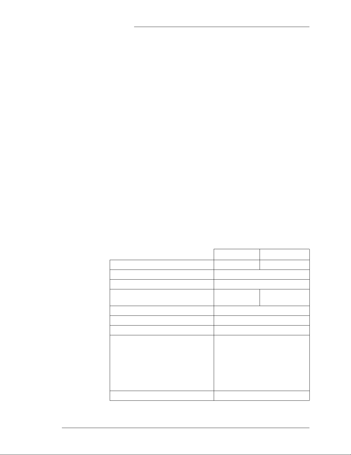
Overview The J85501M-1 Vector Controller (Figure 2-1) is a 1U
rack-mounted controller designed for standard 23 and 26-inch
frames. 19-inch versions are also in development. All I/O
connections and operations can be accessed and performed from
the front of the unit. List 1 and List 2 are full-feature display
controllers. List 3 and List 4 have LED status displays. All units
are front accessible and available in both +24V and -48V
versions. Consult customer service for -24V applications.
Remote access using a modem or network card is available.
Basic controller specifications are summarized in the following
table.
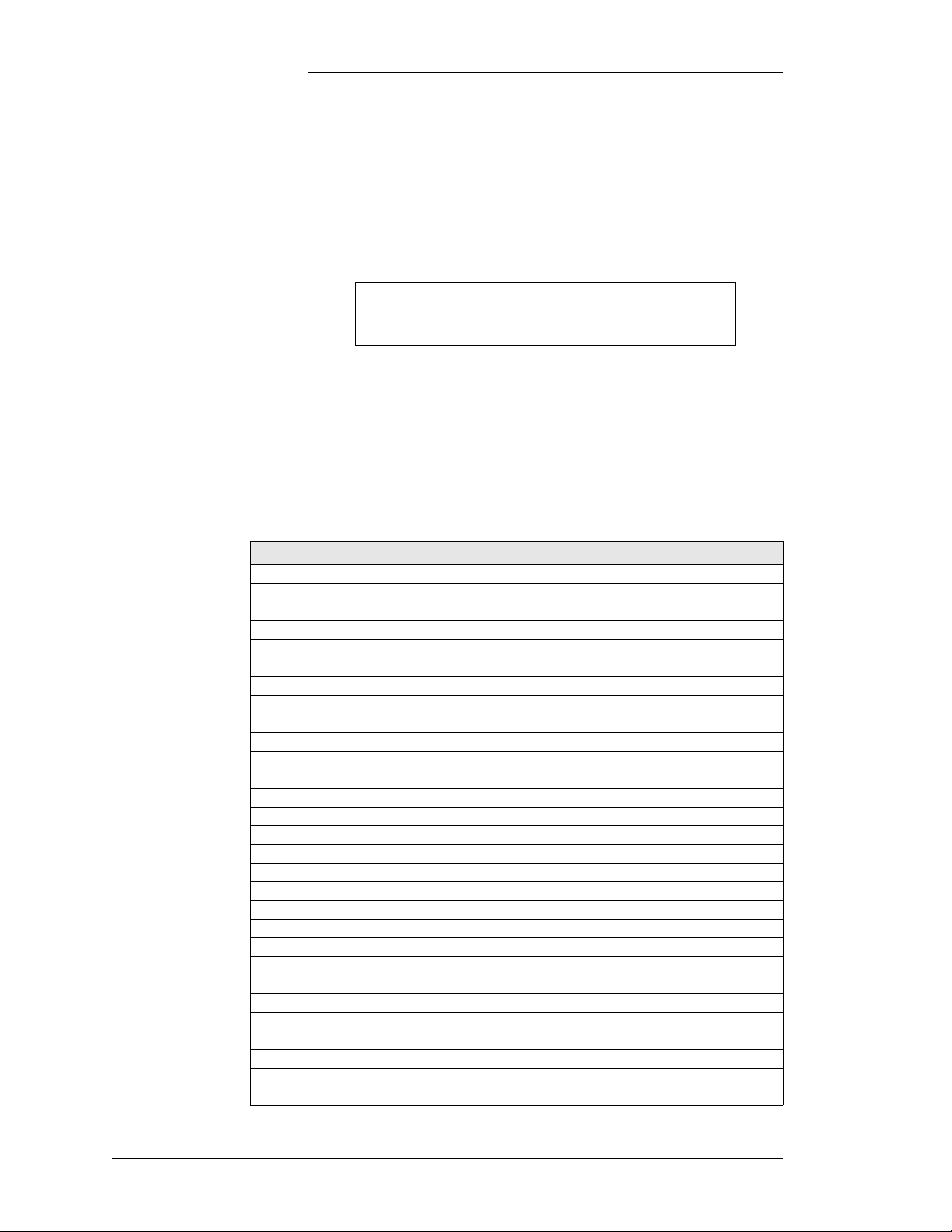
Table 2-A: J85501M-1 Galaxy Vector Controller Specifications
List2, List 4 GCM2 List 1, List 3 GCM3
Input voltage range 19 - 30V 36 - 60V
Maximum input power 4.5W
Form C Alarm contact ratings 60V at 0.3A
Plant voltage measurement accuracy
(±.05% of full scale + 1 count)
Plant voltage measurement resolution .01V
Plant current measurement accuracy ±1% of full scale
Plant current measurement resolution 1A
±30mV ±40mV
• ±3°C for battery temperatures
from -5°C to +55°C
Thermistor temperature measurement
accuracy
• ±5°C for battery temperatures
from -10°C to -5°C
• ±5°C for battery temperatures
from +55°C to +85°C+
Operating temperature range -40°C to +85°C
Issue 2 January 2008 Product Description 2 - 1
Page 16
Galaxy Rack-Mounted Vector Controller J85501M-1
Batteryless Operation The J85501M-1 Controller is suitable for use in power plants
with or without batteries. In batteryless plants, the loss of ac
power causes an immediate loss of dc power to the controller and
the activation of all office alarm relays. When ac power is
restored, plant rectifiers will return to their last specified voltage
set point, and the controller will automatically return to its last
configuration.
1.7"
GCM2 or GCM3
Control Board
21.2"
Weight: 10.5 lb
11"
Figure 2-1: J85501M-1 Galaxy Vector Controller
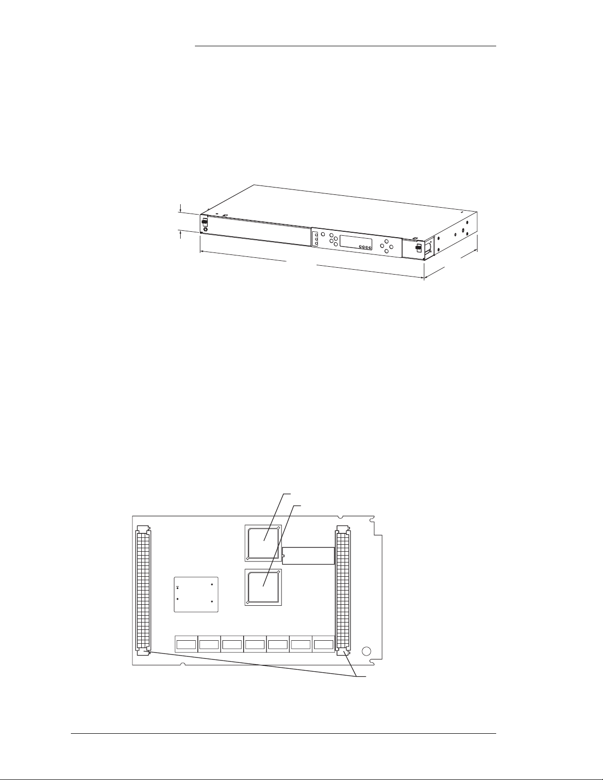
J85501M-1 Controller uses the GCM2 (24V) or GCM3 (48V)
controller boards available in Lineage Power GPS and FMS
systems. This board consists of an embedded microcontroller, A/
D converters, timers, memory, and input/output alarm and
control circuitry with connections to the terminal connection
boards. Software is updated by replacing the controller board. It
is possible to upgrade the software by replacing the memory IC
(IC27), but this method is not recommended. Replacing the
board eliminates directly handling, and possibly causing damage
to the memory IC. There are no hardware user-configurable
items on the GCM boards.
IC27 - Peripheral Support and Memory IC
IC1 - Microcontroller
J1 J3
OUT-
IN
+
OUT+
J1 and J3 - Connect to BUJ1
Figure 2-2: J85501M-1 Vector Controller GCM2 or GCM3
2 - 2 Product Description Issue 2 January 2008
Page 17
Galaxy Rack-Mounted Vector Controller J85501M-1
User Interface
Control Panel
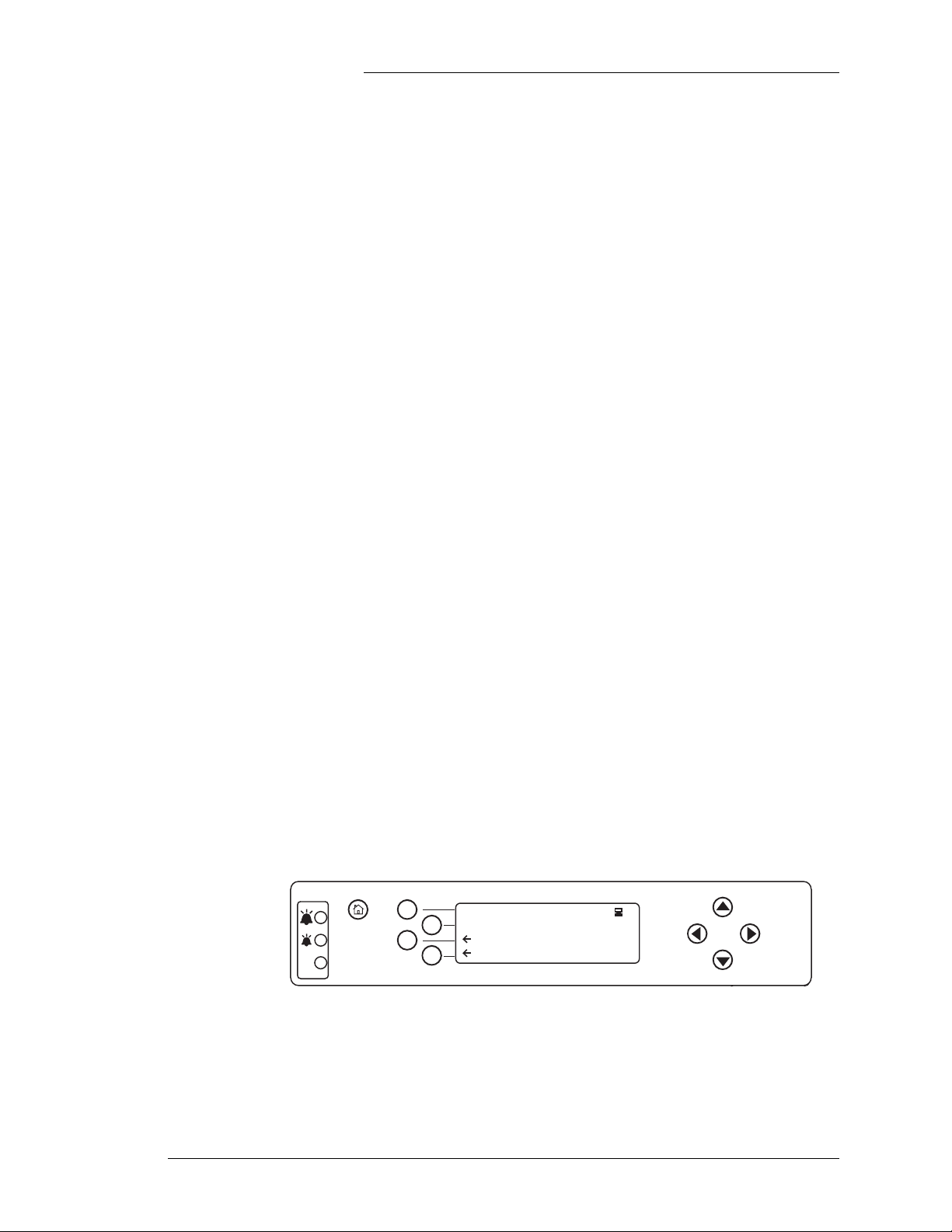
Figure 2-3 shows a view of the 848733907 user interface control
panel used with the J85501M-1 List 1 and List 2. This assembly
interfaces with the BUJ1 connection board via a 14 pin cable
attached to J9, and a 12 pin flex-cable (keypad) to J6. The
848733907 provides a comprehensive user interface to the
controller. It is used to view plant voltage and load, configure
thresholds and other system parameters, view active alarms and
to initiate system operations. This interface consists of a 4 line x
20 alphanumeric character LCD, a nine key keypad, and three
status LEDs. A contrast control potentiometer is located just
behind the display on the BUJ1 board.
J4 (Local Port) A standard DB9 connector (J4) is provided on the BUJ board for
local terminal access. This local port is referenced to the battery
side of the power system. Connecting non-isolated (earth
ground referenced) terminal may cause damage. Laptop
computers running on battery can typically be connected to the
local port. AC line powered terminals, as well as some AC/DC
supplies for computers and laptops are referenced to earth
ground. For these applications isolation is required between the
terminal device and the controller's local port. For cases
requiring isolation a commercially available external port
isolation device, connected through J4 (local port), is required,
or a Lineage Power BSM4 can be purchased and connected
through J5.
J5 (Option Port) A 14 pin connector (J5) provides RS-232 connection to option
boards which provide remote access. These are: optional
network interface card EBW1 Gateway or a BSM3 modem
board. It should be noted that the BSM3 modem board also
provides an isolated RS-232 port.
See Appendix A for more specific details about connecting to
these ports.
+27.74V 820A
OK
FLOAT-COMPENSATED
CUTOFF
View Alarms (5)
AUDIBLE ALRM
Figure 2-3: 848733907 1U Full-Feature Control Panel
Four softkeys are located directly to the left of the display. The
labels and functions of these buttons change dynamically as you
Issue 2 January 2008 Product Description 2 - 3
Page 18
Galaxy Rack-Mounted Vector Controller J85501M-1
make selections and perform system operations. Softkey labels
appear in the display window and are preceded by a "←".
Four navigation keys (up, down, left, and right arrow keys) are
located to the right of the display. These keys are used to
navigate through the controller menus.
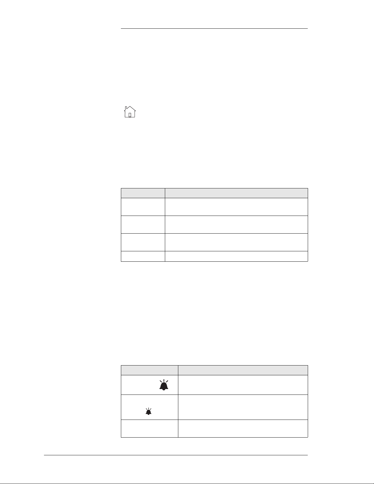
The home key, located directly to the left of the four
softkeys, brings you:
• to the main menu from the default screen or any sub-menu
• to the default screen from the main menu
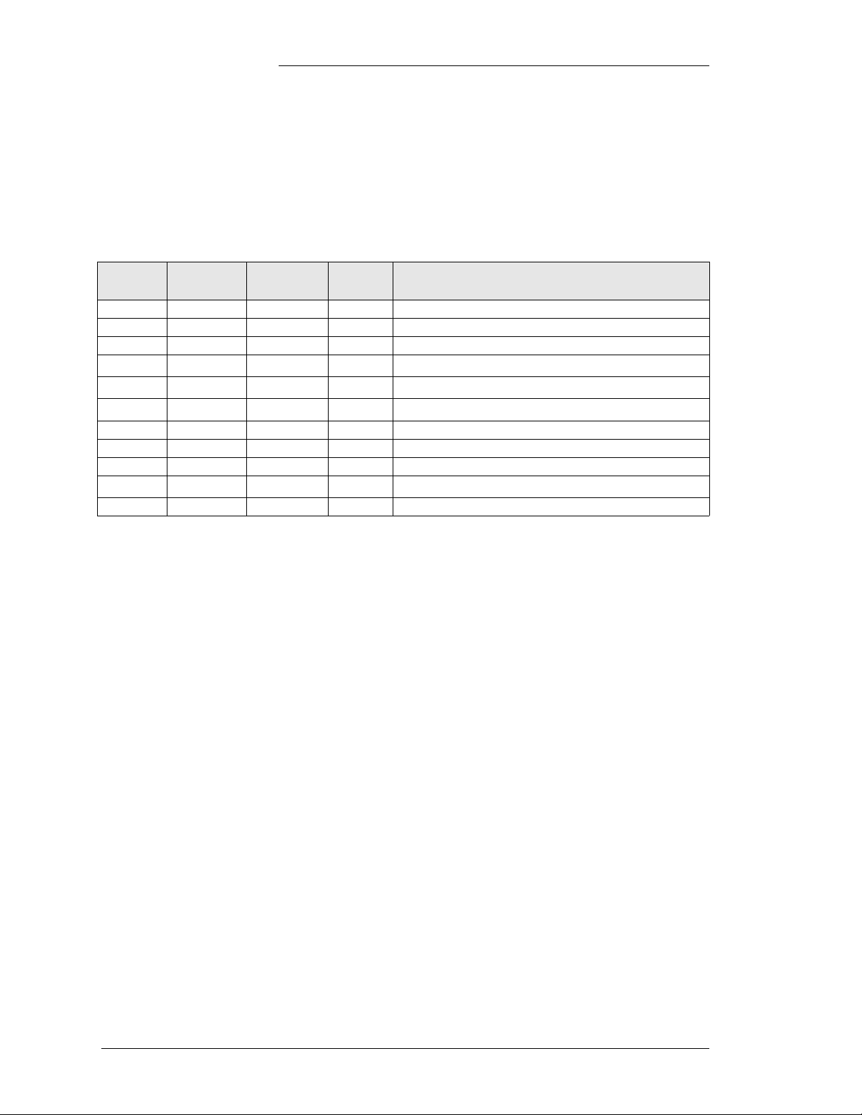
The following table lists the user interface control panel keys
and functions.
Table 2-B: Control Panel Keys and Functions
Key Function
Softkeys
Move through the various features and menu structure of
the controller
Left and Right
Arrow Keys
Up and Down
Arrow Keys
Home Key Return to top level of menu structure or default screen
Move through digits in edit screens
Scroll or select a configuration option or value in an edit
screen
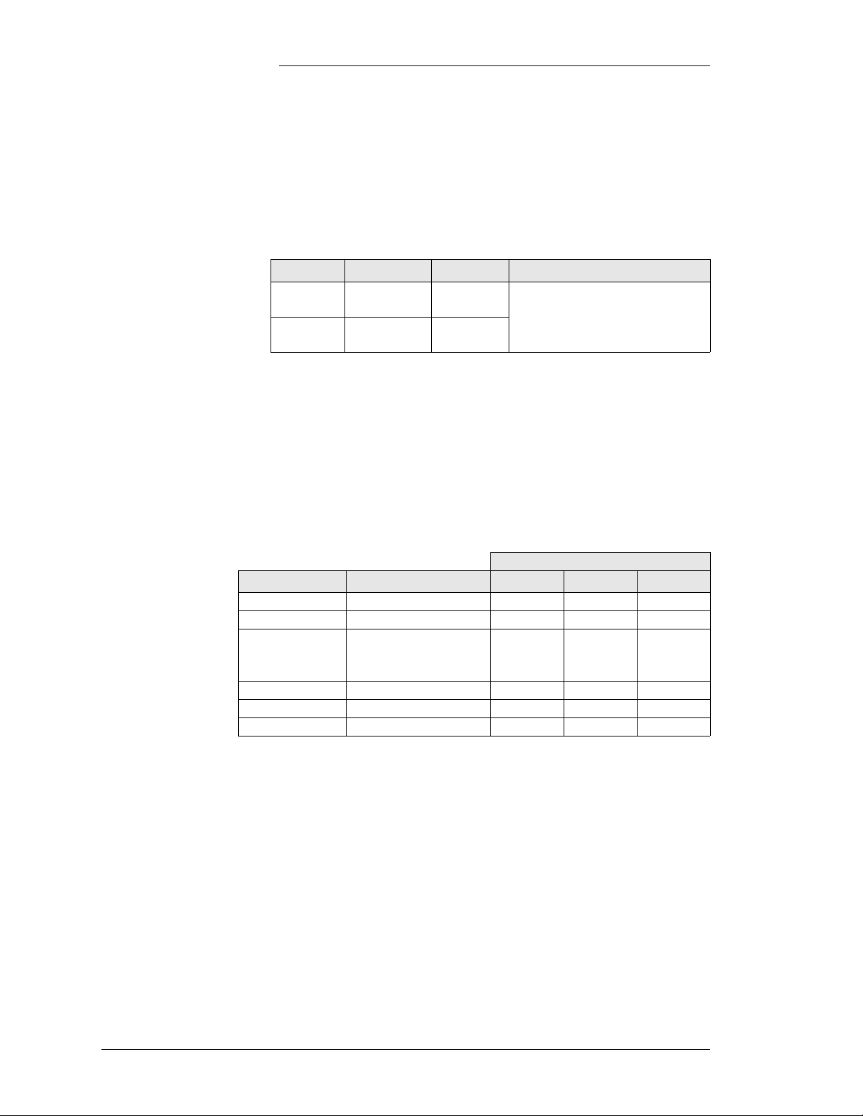
Three alarm status LEDs give a visual indication of system
status. The Major and Minor alarm LEDs indicate when alarms
are present, and then the actual alarm descriptions can be
displayed on the LCD by pressing the Alarms softkey. LED
indications are described in the following table. The J85501M-1
List 3 and List 4 controllers utilize only the LED status
indicators. Using this display option requires local terminal
access for obtaining plant details and troubleshooting
problems.See Figure 2-4.
Table 2-C: Control Panel LEDs and Functions
LED Indication
MAJOR (red)
A Major alarm is active. If the MAJOR LED is lit,
MINOR and OK LEDs will not be lit.
MINOR
(amber)
OK (green)
2 - 4 Product Description Issue 2 January 2008
A Minor alarm is active. If the MINOR LED is lit,
there are no Major alarms active and the MAJOR
and OK LEDs will not be lit.
No alarms are active. If the OK LED is lit, MAJOR
and MINOR LEDs will not be lit.
Page 19

Galaxy Rack-Mounted Vector Controller J85501M-1
CURRENT
VOLTAGE
STATUS
PMJ PMN
OK
Figure 2-4: 848575841 List 3 / List 4 Display Panel
On the full-feature display, the default screen shows system
voltage and current, system mode (FLOAT or BOOST and other
system conditions), and any active alarms. The display will
return to the default screen from any menu whenever there has
been no user initiated activity for three minutes.
All power system attributes are characterized into three main
categories by the Vector Controller:
Status Information Only
View system voltage, system load, alarms, etc.
Control/Operations Perform System Functions
Put the system into float or boost mode, perform plant
battery test, etc.
Configuration Set System Parameters
Set float/boost voltage, enable/disable system features,
etc.
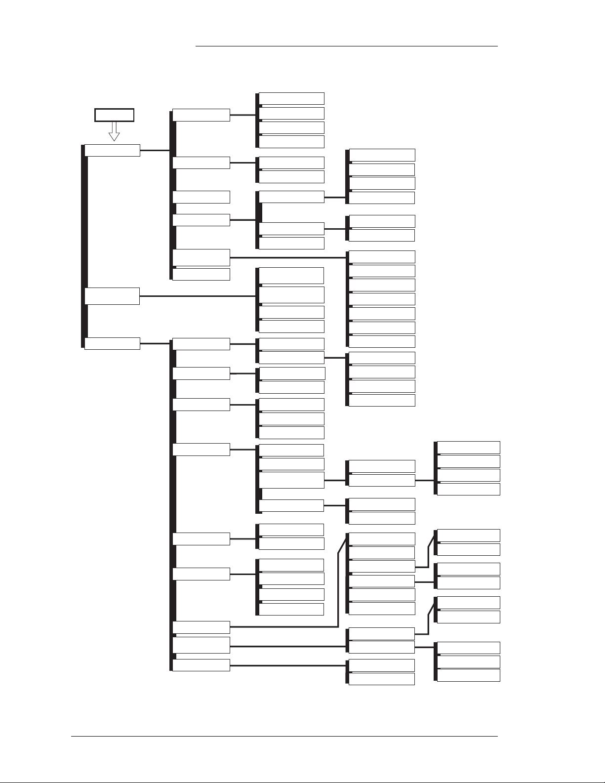
Figure 2-5 shows a menu map of the controller software. In the
Configuration section, there are two types of edit screens:
numeric and scroll lists. Numeric edit screens are those on which
you modify numbers by changing the individual digits in the
number. An example is the Float Set Point screen. Scroll list edit
screens are modified by pressing the UP and DOWN buttons to
scroll through a list of possible settings. These lists may include
numeric values or text. Selecting a Shunt Type is an example of
a scroll list edit.
Issue 2 January 2008 Product Description 2 - 5
Page 20
Main Menu
View Status
Galaxy Rack-Mounted Vector Controller J85501M-1
Battery Test Results
Batteries
Converters
Rectifier Current
Current
Temperature Probes
TYPE
VOLTAGE
CURRENT
Float Voltage Alrms
HIGH MAJOR
HIGH MINOR
BD MAJOR
LOW MAJOR
Control/
Operations
Configuration
Alarm Thresholds
Enable/Disable
Info
SOFTWARE VER
Float Voltages
Rectifiers
Shunts
Batteries
Contactors
Converters
Boost
Communication
Ports
Calibrate to Meter
Boost Voltage Alrms
BATT TEMP MJ
Start/Stop
Battery Test
Start
Lamp Test
Clear Events
Start/Stop Boost
Set Point
Voltage Alarms
Current Limit
No. On Engine
Type
Shunt 1 Rated
Shunt 2 Rated
Type
Batt Test Enable
Batt Temp
Management
Limit Recharge
Contactor 1
Contactor 2
Set Point
Shutdown At
Shutdown Enable
Restart At
HIGH MAJOR
HIGH MINOR
BATTERY TEST
BOOST FEATURE
AUTO BOOST
CONV SHUTDOWN
TEMP COMP
LOW TEMP COMP
RECHARGE LIMIT
High Major
High Minor
BD Major
Low Major
Temp Alarm
Temp Compensation
Limit Enable
Limit At
Boost Enable
Set Point
Boost Voltage Alrms
Auto Boost
Manual Dur
Boost Current Lmt
Local Port
Modem Port
System Voltage
Converter Voltage
Temp Comp Enable
High Temp Comp
Nominal Temp
Low Temp Comp
High Major
High Minor
Auto Boost Enable
Auto Duration
Baud Rate
Handshake
Baud Rate
Handshake
Rings to Answer
Figure 2-5: J85501M-1 Vector Controller Display Menu Flow
2 - 6 Product Description Issue 2 January 2008
Page 21
Galaxy Rack-Mounted Vector Controller J85501M-1
BUJ Terminal
Connection
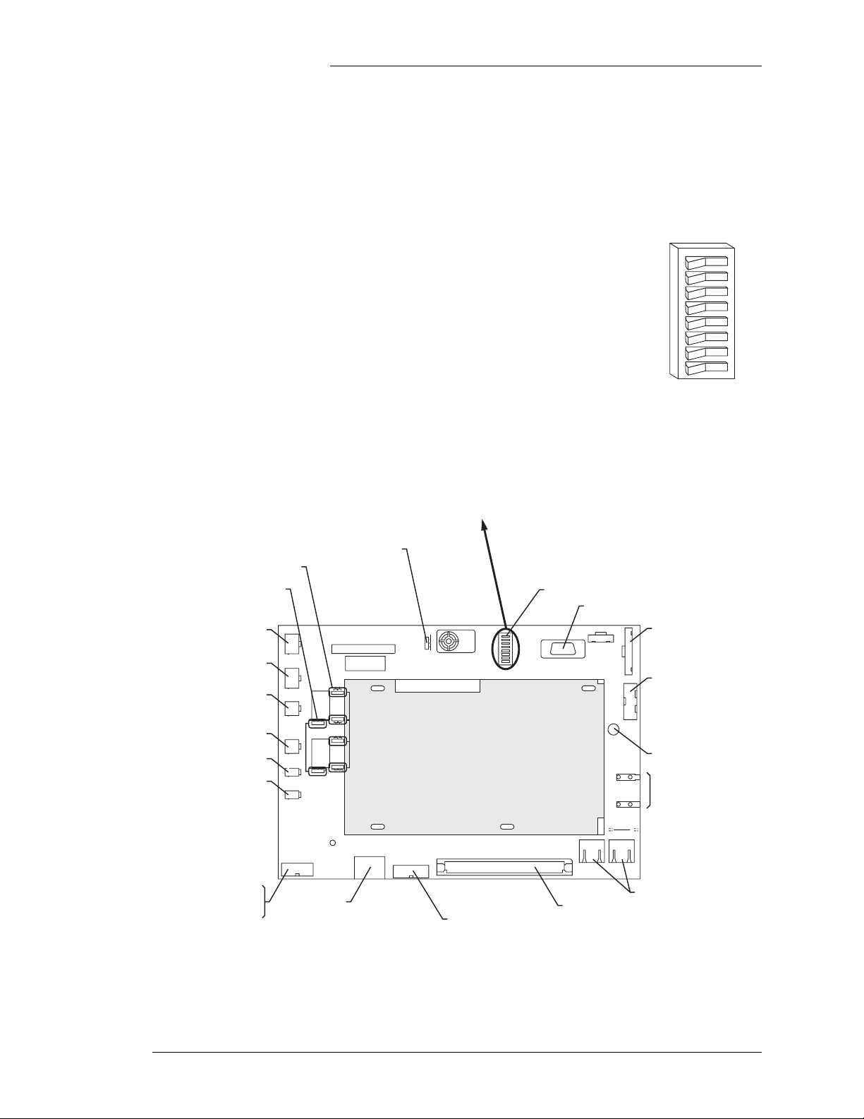
Figure 2-6 shows the BUJ Terminal Connection Board. The
following pages describe the required connections. Note: To
make connections to the 1U_ALM Board terminal blocks, pull
Board
S1.1: Front Panel Configuration
0
- Enabled (shown)
1
- Disabled
S1.2: Software Mode
- Standard (shown)
0
- Custom Default Configuration Parameters
1
S1.3: Option Card Availability
- Modem
0
- Galaxy Gateway Card (Internet)
1
S1.4: Rectifier Class
01- Standard GPS Rectifiers
- NP/AC3000 Rectifiers
1. Setting both SW1.2 and SW1.5 to "1" will result in activating the HV alarm cont act.
2. SW1.2 setting will only be read by the software when the GCM is powered up.
3. HV alarm contacts used for 2ACF alarm instead of HV alarm.
4. Cycling from "0" to "1" and back to "0" will reset the display.
the front of the insulating cover off of the mounting posts.
S1.5: Alarm Contact Select
0
- Standard HV, High Voltage
1
- VLV, Very Low Voltage
1,2
S1 DIP Switch Settings
S1.6: - Set to 0
3
S1.7: Plant Battery Test
- Disabled (shown)
0
- Active
1
S1.8: - Display Reset
- Normal (shown)
0
- Reset Display
1
4
1
8
7
6
S1
5
4
3
2
1
01
J11,J12,J18,J19:
24V / 48V Selection Jumpers
J15,J20: LVD Force-On Jumpers
J3: Thermal Probe 2
or 210E
J1: Thermal Probe 1
or 210E
J14: LVD2
J13: LVD1
J17: FAJ Input
J16: AMJ Input
P5: Power
Shunt
Vsense
J21: Manual Buzzer
Disable Jumper
J3
THERM 2
1
J1
48V
24V
THERM 1
1
LVD2
1
J13
LVD1
1
J17
1
FAJ
J16
AMJ
POWER
P5
J19
-
+
1
J14
J18
1
J20
48V
24V
24V
48V
FORCE ON
-
+
1
1
AUTO
48V
1
J15
24V
FORCE ON
ABS FUSE
1 1/3A
FH1
ABS Fuse
S1: DIP Switch
J4: Local RS-232 DB9 Port
OFF
J21
1
ON
BUZ1
S1
8
7
6
5
4
3
2
1
1
LOCALRS232
J4
0
HDR3
J6
Keypad
KEY PAD
Display
DISPLAY
J9
GCM Board
HDR1 HDR2
TERM RES
8
8
BUJ Board
A32
RS232
OPT
J5
C32
2
1
A1
J8
B1
C1
RS485
P2
Display Contrast Control
Potentiometer
TJ1
BLK/NEGRO
T
System Voltage and
N
SHU
PLANT V
TJ2
Shunt Test Points
RED/ROJO
R10
2
1
J7
J7,J8: RS-485 to Rectifiers
P2: Alarm Board
J5: BSM3/BSM4 Modem
or EBW1 Ethernet Board
Figure 2-6: J85501M-1 Vector Controller / BUJ Terminal Connection Board
Issue 2 January 2008 Product Description 2 - 7
Page 22
Galaxy Rack-Mounted Vector Controller J85501M-1
BUJ1 Power, Sense
and Shunt
Connections
Power and other primary signal connections from the system
(factory wired in FMS). BUJ/Vector Controller power input
connections are not polarity sensitive, so the BUJ and controller
boards will operate regardless of BAT and DG polarity.
However, the operation of alarms and Vsense inputs are
affected, and the following guidelines should be used.
.
Table 2-D: Power / Main Signal Connections
Alarm
Input Wire Color BUJ
BAT Yel lo w P5.7 Charge Bus (Rectifier bus)
DG White P5.1 Discharge Return Bus
P5.2, P5.3 no connection
Shunt2+
Vsense-
Shunt1+
FAJ Vio let P5.8, J17.1 TB4.6 Distribution fuse alarm (see Alarm Inputs)
CG Orange P5.9 Bus on which shunts are mounted
Shunt2- Blue P5.10 TB1.9 Most negative side of second shunt while on discharge
Vsense+
Shunt1- Black P5.12 TB1.12 Negative side of shunt while on discharge
Brown P5.4 TB1.8
Red P5.5 TB1.4 Negative remote regulation battery sense point
Green P5.6 TB1.11 Most positive side of shunt while on discharge
2
Slate (Gray) P5.11 TB1.2 Positive remote regulation battery sense point
Board
Plant Termination
BAT: Connection to the battery discharge bus for controller
power, and fused through on-board F1. It is +24V for the GCM2,
and -48V for the GCM3. BAT input is typically the bus in which
circuit breakers and fuses are installed for distribution, and
therefore the alarm input potential. It is the ungrounded side of
the dc bus. For applications where this connection is made
outside of the frame/bay, this lead should be fused with a 3 to 5
amp fuse.
DG: Connection to battery return (discharge ground) bus. DG
provides the return for BAT (controller power) and ABS loads.
Connections are available on TB2 pins 11 and 12 on the alarm
board, and P5 pin 1 on the BUJ. DG input to the BUJ must be the
bus voltage opposite to the alarm inputs (BAT) bus. It is
connected to the grounded side of the dc bus.
SHUNT1+, SHUNT1-, SHUNT2+, SHUNT2-: Shunts must be
rated for 50mv full scale. The BUJ1 does not require series
impedance in these leads for circuit measurements. However,
the leads should be fused protected (1A or less) at the shunt prior
to sending the signal to the J85501M-1. The circuit can handle
the standard Lineage Power 100K 1% resistors in series with the
shunt which can also be used to limit the current.Shunt
2 - 8 Product Description Issue 2 January 2008
Page 23

Galaxy Rack-Mounted Vector Controller J85501M-1
connections are available on both the alarm board and the BUJ
board.
Vsense: Typically connected to the battery bus. Vsense+ is
connected to the positive dc potential, and Vsense- to the
negative. The GCM recognizes plant voltage sense inputs on the
BUJ board. Polarity of sense inputs must be observed. Incorrect
polarity will display incorrect plant voltage. Vsense leads should
be fused with a 1A or smaller fuse at the source. These signals
are available on both the alarm board and the BUJ board.
CG: (Controller Ground) determines the controller ground
reference. The controller ground reference is connected
according to the location of the plant shunts being monitored. If
the shunts are located in the battery side of the DC bus, then
(CG) should be connected to the battery side of the DC bus. If
the shunts are located in the Discharge Ground (DG) side of the
dc bus, then CG must be connected to the Discharge Ground
(DG) side of the DC bus. Note: All shunts installed must be in
the same side of the DC bus. Either side of the shunt can be used
as the reference, but best practice is to connect the reference to
the more negative side of the shunt. For shunts in the hot side,
this lead should be protected with a 1A to 4A fuse.
Alarm Inputs Basic office and contactor state alarm inputs. These inputs are
closures to BAT or provided ABS input with the exception of the
PBT signal that requires a closure to CG. All connections can be
made with the provided 1U-ALM terminal block termination
board 848711933.
Table 2-E: BUJ Alarm Input Terminals
Name Description
AMJ Auxiliary major alarm input TB4.2 J16.1 Closure to Batt
FAJ Fuse major alarm input TB4.6 P5.8/J17.1 Closure to Batt
LVD1O Low voltage disconnect contactor 1 open status input TB3.4 J13.2 Closure to Batt
LVD2O Low voltage disconnect contactor 2 open status input TB3.9 J14.2 Closure to Batt
MAINT Maintenance (open connector) TB4.10 - Open to Batt
Alarm
Board
BUJ1 Alarm Asserted
Issue 2 January 2008 Product Description 2 - 9
Page 24
Galaxy Rack-Mounted Vector Controller J85501M-1
LVD1, LVD2 Relay contact outputs for LVD contactor control. Contacts are
rated for 10 amps. Power must be provided externally to the
contactor coil. The contactor coil should have battery
permanently attached. The LVD1 and LVD2 contacts should
complete the circuit to DG. This power is switched by the LVD
control contact closure provided.
Table 2-F: LVD Drive Terminals
Office Alarm Relay
Outputs
ACF Single AC Fail TB8.1 TB8.2 TB8.3
BD Battery on Discharge TB8.9 TB8.10 TB8.11
HV/2ACF/VLV
MJF Major Fuse TB7.9 TB7.10 TB7.11
PMJ Power Major TB7.1 TB7.2 TB7.3
PMN Power Minor TB7.5 TB7.6 TB7.7
1. C: Open contacts. Closed to R(C) when alarm condition exists.
2. Relay assignment is determined by the settings of S1.2 and S1.5:
Contactor Name
LVD1
LVD2
LVD1-CON1
LVD1-CON2
LVD2-CON1
LVD2-CON2
Alarm Board
TB3.6
TB3.7
TB3.11
TB3.12
Description
Dry closure provided. External
power required.
All alarm output relays are isolated Form C or transfer type
contacts, consisting of Open (O) and Closed (C) contacts, with a
common Return (R(C)) contact. The de-energized state of the
controller forces these contacts to the alarm state. An alarm
condition results in a closure of the Closed contact to the Return
contact, and an open between the Open and Return contacts.
Table 2-G: BLJ3 Office Alarm Relay Output Terminals
Terminal
Alarm Alarm Description
High Voltage / Multiple
2
AC Fail / Very Low
Vo l t a g e
R(C): Return (common)
O: Closed contacts. Open to R(C) when alarm condition exists.
HV alarm S1.2-0, S1.5=0
2ACF alarm S1.2=1, S1.5=0
VLV alarm S1.2=0, S1.5=1
Setting both switches to 1 results in activating HV. The S1.2 setting is only read during
GCM power up.
1
C
TB8.5 TB8.6 TB8.7
R(C)
1
1
O
Auxiliary Battery
Supply (ABS)
Auxiliary Battery Supply (ABS) is connected to the battery
discharge bus and fused through F1 (1-1/3A) for user application
on TB4 pins 1, 3, 5, 9, and 11, and TB5 pin 1. F1 is field
replaceable.
2 - 10 Product Description Issue 2 January 2008
Page 25
Control Signal Inputs
Galaxy Rack-Mounted Vector Controller J85501M-1
Table 2-H: BUJ1 Control Signal Inputs
Signal Description
Thermal Probe
Connections
Alarm
Board
PBT Plant Battery Test TB4.8 Closure to PBT_RTN (TB4.7)
RO Reserve Operation TB4.4 Closure to Batt
Alarm Asserted
See Section 3 for details on the Plant Battery Test and Reserve
Operation features.
Four thermistor or 210E module inputs are provided on the
alarm termination board, and two thermal probe inputs are
provided at J1 and J3 on the BUJ1. These connectors will accept
standard Lineage Power thermal cables or 210E cables. J1 and
J3 provide cable access to RTH1 and RTH2 thermal probes,
respectively. If connections are made at J1 and J3 then they
should not be made at the terminal blocks and vice versa. Access
to all four thermistors is available at the terminal block. Each
thermistor is connected to the RTH#+ and RTN#, where # = 1
through 4. A strap is required across RTH#+ and EN#+ for each
thermistor input used. The strap is not required when using 210E
modules.
RTH ALM, RTH ALMR: Thermistor alarm input and return
from 210E module. See Section 4 for 210E module connections.
Table 2-I: RTH ALM, RTH ALMR Terminals
Signal Terminal Signal Terminal
RTH1_EN TB6.7 RTH3_RTN TB5.11
RTH 1_RTN TB6.8 RTH3 + TB5.12
RTH 1+ TB6.9 RTH4_EN TB5.6
RTH2_EN TB6.3 RTH4_RTN TB5.7
TRH2.RTN TB6.4 RTH4+ TB5.8
RTH 2+ TB6.5 RTH_ALM TB6.11
RTH3_EN TB5.10 RTH_ALMR TB6.12
Rectifier Connections J7, J8: RJ45 connectors for the serial RS-485 rectifier and
equipment interface. These are parallel connectors and can be
used interchangeably.
Communication Port J5: RS-232 serial communication port used with the optional
BSM3 modem boards or EBW1 Gateway board (see Appendix
A).
Issue 2 January 2008 Product Description 2 - 11
Page 26
Galaxy Rack-Mounted Vector Controller J85501M-1
Miscellaneous TPT1, TPT2: Thermistor protected test points for access to
system voltage available on the front panels of systems without
display. They can also be accessed on models with display by
opening the controller unit and probing the “Plant VI” and
“Shunt” PWB pads.
F
S1
F
O
2
M
J3
R
E
H
T
1
1
M
J1
R
E
V
H
48V
24
J19
T
1
-
+
1
J14
2
D
LV
1
J18
1
N
J20
O
48V
24V
E
C
R
8V
4V
O
4
2
F
-
+
J13
1
1
D
LV
1
O
T
U
1
A
J17
1
48V
1
J
A
N
J15
F
O
24V
E
ORC
F
J16
MJ
A
ABSFUSE
1 1/3A
POWER
1
5
P
H
F
J5
1
J2
1
N
O
32
2
S
R
T
P
O
BUZ1
GCM Board
BUJ Board
A32
C32
8
7
6
5
4
3
2
1
1
HDR3
J6
LOCAL RS232
J4
0
D
A
YP
E
K
Y
A
L
P
IS
D
J9
TJ1
BLK/NEGRO
System Voltage and
SHUNT
PLANT V
TJ2
RED/ROJO
Shunt Text Points
R10
HDR1 HDR2
TERMRES
8
2
8
2
1
1
A1
J8
J7
B1
C1
RS485
P2
Shunt
Measurement
TJ1
Plant Voltage
Measurement
BLK/NEGRO
SHUNT
TJ2
PLANT V
RED/ROJO
J9: 14-pin connector to the LCD display.
J6: 12-pin connector to the Membrane (Keypad) panel.
P1, P3: GCM board mounting connectors.
J21: For List 3 and List 4, this jumper may be used for
temporarily disabling the audible alarm. Placement of the
jumper is identified by silkscreen on the BUJ board.
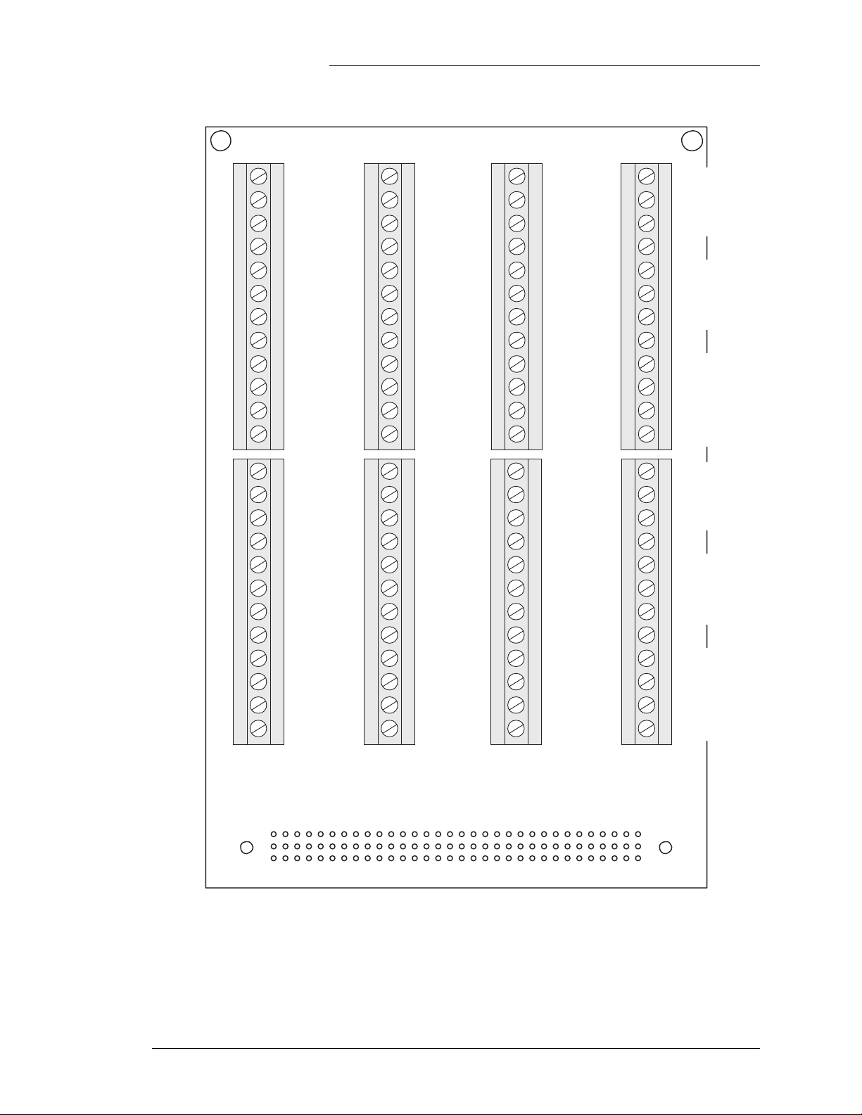
1U_ALM Board Terminal Blocks
P2 on the BUJ board interfaces with the 1U_ALM terminal
block board. Signals found on the 1U have been previously
described. Figure 2-7 shows the 1U_ALM Board terminal
blocks and their signal designations.
2 - 12 Product Description Issue 2 January 2008
Page 27
Galaxy Rack-Mounted Vector Controller J85501M-1
10
11
12
10
11
12
TB1
1
2
3
4
5
6
7
8
9
1
2
3
4
5
6
7
8
9
Vsense+
Vsense-
Shunt2+
Shunt2-
Shunt1+
Shunt1-
FRMGND
FRMGND
FRMGND
CG
CG
DG
DG
10
11
12
10
11
12
TB3
1
2
3
4
5
6
7
8
9
1
2
3
4
5
6
7
8
9
FRMGND
LVD1_ST
LVD1_RTN
LVD1_CON1
LVD1_CON2
LVD2_ST
LVD2_RTN
LVD2_CON1
LVD2_CON2
ABS
AMJ
ABS
RO
ABS
FAJ
PBT_RTN
PBT
ABS
MAINT
ABS
10
11
12
10
11
12
TB5
1
2
3
4
5
6
7
8
9
1
2
3
4
5
6
7
8
9
ABS
FRMGND
RTH4_EN
RTH4_RTN
RTH+
FRMGND
RTH3_EN
RTH3_RTN
RTH+
CG
CG
RTH2_EN
RTH2_RTN
RTH+
FRMGND
RTH1_EN
RTH1_RTN
RTH+
FRMGND
RTH_ALM
RTH_ALMR
10
11
12
10
11
12
1
2
3
4
5
6
7
8
9
1
2
3
4
5
6
7
8
9
TB7
PMJ_C
MPJ_R
MPC_O
PMN_C
PMN_R
PMN_O
MJF_C
MJF_R
MJF_O
FRMGND
ACF_C
ACF_R
ACF_O
HV_C
HV_R
HV_O
BD_C
BD_R
BD_O
FRMGND
TB2
TB4
TB6
TB8
Figure 2-7: 1U_ALM Board Terminal Blocks
Issue 2 January 2008 Product Description 2 - 13
Page 28
Galaxy Rack-Mounted Vector Controller J85501M-1
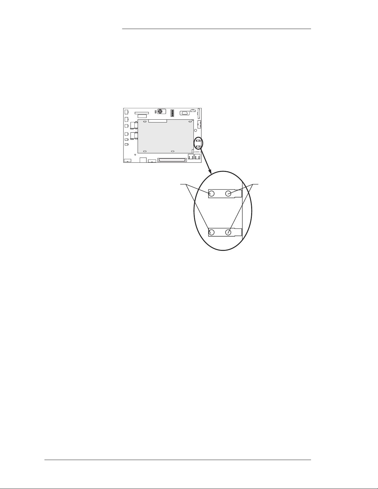
J11, J12, J18, J19: Select between 24V and 48V systems. All
jumpers must be set.
J11, J12, J18 and J19
24V / 48V Selection Jumpers
48V
Position
48V
J19
J18
48V
48V
FORCE ON
48V
CE ON
24V
24V
24V
24V
24V
Position
48V
J19
J18
48V
48V
FORCE ON
48V
CE ON
24V
F
S1
F
O
2
M
J3
R
E
H
T
1
1
M
J1
R
E
V
H
48V
24
J19
T
1
-
+
1
J14
2
D
LV
1
24V
24V
J18
1
N
J20
O
48V
24V
E
C
R
8V
4V
O
4
2
F
-
+
J13
1
1
D
LV
1
O
T
U
1
A
J17
1
48V
1
J
A
N
J15
F
O
24V
E
ORC
F
J16
J
M
A
ABSFUSE
1 1/3A
POWER
1
5
P
H
F
J5
J21
1
N
O
32
2
S
R
T
P
O
BUZ1
GCM Board
BUJ Board
A32
C32
8
7
6
5
4
3
2
1
0
1
24V
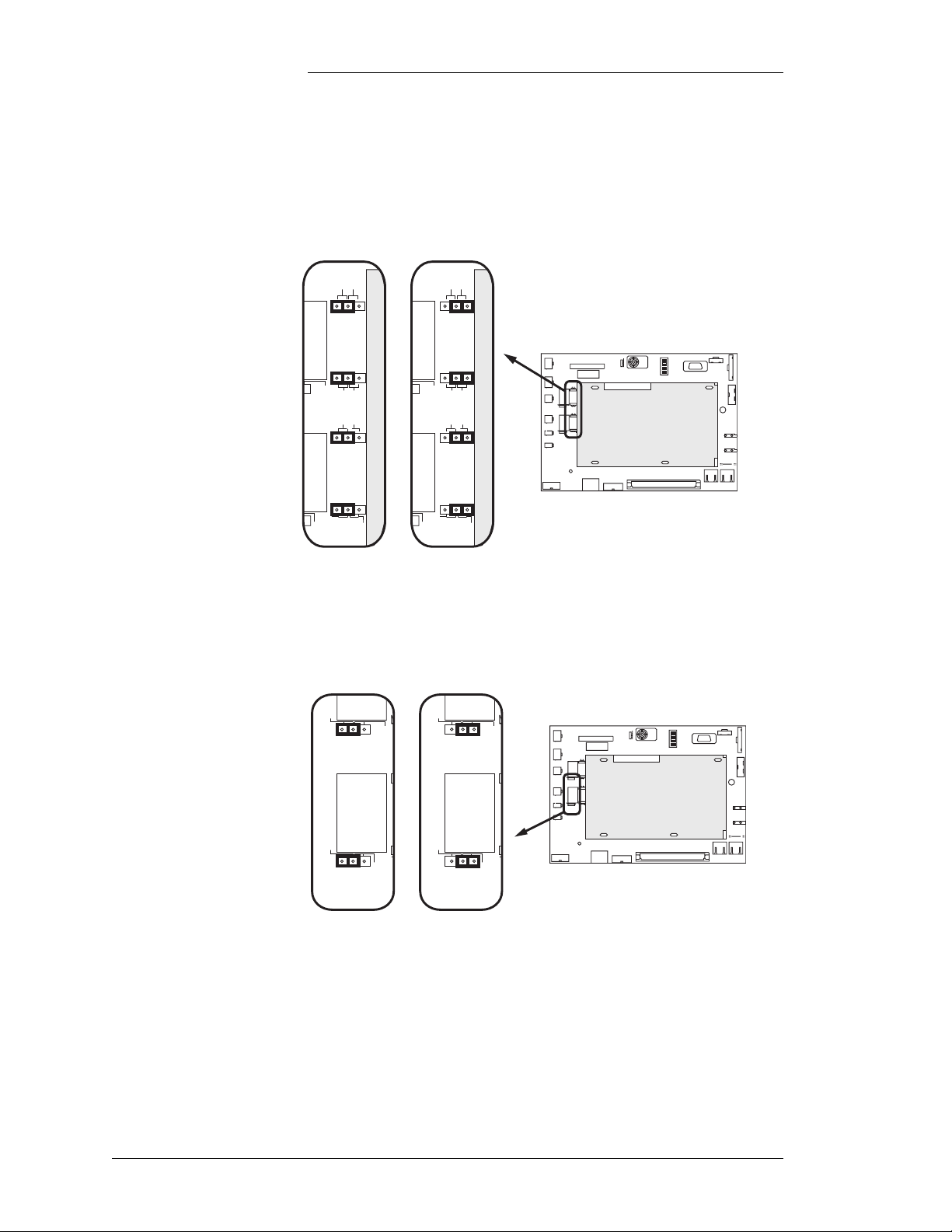
J15, J20: Used to force the LVD contactor closed.
J15 and J20
LVD Force-On Jumpers
HDR3
J6
LOCAL RS232
J4
D
EYPA
K
Y
A
L
ISP
D
J9
TJ1
BLK/NEGRO
SHUNT
PLANT V
TJ2
RED/ROJO
R10
HDR1 HDR2
TERMRES
8
2
8
2
1
1
A1
J8
J7
B1
C1
RS485
P2
AUTO
J20
AUTO
48V
J15
Contactor in
Auto Mode
FORCE ON
FORCE ON
AUTO
J20
AUTO
J15
Contactor
Forced On
48V
FORCE ON
FORCE ON
F
S1
F
O
8
M2
J3
R
E
H
T
1
M1
J1
R
E
V
H
48V
24
J19
T
1
-
+
1
J14
2
D
LV
1
J18
1
N
J20
O
48V
24V
E
C
V
V
48
24
FOR
-
+
J13
1
1
LVD
1
O
T
U
1
A
J17
1
48V
1
J
N
J15
4V
FA
O
2
E
ORC
F
J16
J
M
A
ABSFUSE
1 1/3A
POWER
1
5
P
H
F
J5
J21
1
N
O
GCM Board
2
23
S
A32
R
T
P
O
BUZ1
BUJ Board
C32
7
6
5
4
3
2
1
0
1
HDR3
J6
LOCAL RS232
J4
D
YPA
E
K
Y
A
L
P
IS
D
J9
TJ1
BLK/NEGRO
SHUNT
PLANT V
TJ2
RED/ROJO
R10
HDR1 HDR2
TERMRES
8
2
8
2
1
1
A1
J8
J7
B1
C1
RS485
P2
2 - 14 Product Description Issue 2 January 2008
Page 29

Galaxy Rack-Mounted Vector Controller J85501M-1
3 Operation
Office Alarm Contacts
Alarm Descriptions
Very Low Voltage
Alarms and Battery
on Discharge
The J85501M-1 Vector Controller issues PMJ, PMN, MJF, BD,
ACF and HV/2ACF/VLV office alarms from the BUJ board.
Refer to Table 2-G for a description of their output terminals.
Refer to Table 3-A for a listing of the various available alarms.
Refer to Table 3-B for a listing of alarm relays and their
associated front panel LEDs.
To see active alarms, press the Active Alarm softkey, then use
the ∧ or ∨ keys to page through alarms. See Tables 3-A and 3-B.
The alarms are listed in order of severity. Some abbreviations are
required to fit the LCD screen.
When system voltage drops below the battery voltage, the
batteries start providing current to the load. Any time that the
plant voltage is below the threshold selected for BD, the Battery
on Discharge alarm activates. If the plant voltage continues to
drop, a second, lower threshold can be reached, activating a Very
Low Voltage alarm. These thresholds can be changed in the
configuration menu. S1.5 set to “1” will allow the relay
dedicated for HV/ACF/VLV to be asserted for the VLV
condition.
Note that a BD alarm does not necessarily mean that the batteries
are discharging, only that the present voltage is lower than the
set point for this alarm. This alarm may be activated by an
incorrectly set BD threshold or plant voltage set point.
Following the restoration of ac power after a battery discharge of
significant depth, this alarm remains active for some time during
the recharge period, until the batteries have recharged to a level
which allows the plant voltage to rise above the BD threshold.
Issue 2 January 2008 Operation 3 - 1
Page 30
Galaxy Rack-Mounted Vector Controller J85501M-1
BD threshold default is set at 25.54V standard in 24V systems,
and 51.1V in 48V systems with slope thermal compensation
disabled. In systems with slope thermal compensation, the BD
threshold should be 0.5V below the slope upper temperature
voltage for 24V systems, and 1.0V below the slope upper
temperature voltage for 48V systems. The slope upper
temperature equals:
Float Set Point - (number of cells) · E · (F-D)
See Figure 3-1 for system settings E, F, and D
These levels generally avoid nuisance alarms from transient
conditions yet provide alarm indications early in a true BD
event, so that sufficient time is provided for maintenance
personnel to respond before battery reserve is exhausted. VLV
should be activated towards the end of the battery reserve
voltage to indicate a critical service condition.
Table 3-A: Alarm Identification Standard Assignments
Alarm Description Alarm Status Front Panel LED GCM Relay
No active alarms present Norm Green None
Very low voltage Major Red None
Battery on discharge Major Red BD
High float voltage Minor Yel l ow None
Very high voltage Major Red HV
Voltage sense fuse alarm Major Red None
AC fail Minor Yel l ow ACF
Multiple AC fail Major Red ACF
Rectifier fail Minor Yel l ow None
Multiple rectifier fail Major Red None
Rectifier ID conflict Major Red None
Rectifier manual off alarm Minor Ye ll o w None
Rectifier AC phase alarm Minor Ye ll ow None
Converter fail Minor Ye l lo w None
Multiple converter fail Major Red None
Converter ID conflict Minor Ye l lo w None
Converter distribution alarm Major Red MJF
Converter fan fail minor Minor Ye l lo w None
Converter fan fail major Major Red None
Fuse alarm major Major Red MJF
Auxiliary input major Major Red None
Load Share imbalance Minor Ye ll o w None
Contactor 1 open Major Red None
Contactor 1 failed Major Red None
Contactor 2 open Major Red None
Contactor 2 failed Major Red None
High battery temperature Major Red None
Temperature probe failure Minor Ye ll ow None
Maintenance open alarm Major Red None
3 - 2 Operation Issue 2 January 2008
Page 31

Galaxy Rack-Mounted Vector Controller J85501M-1
Table 3-B: Office Alarm Relay and Front Panel LED Standard Assignments
Asserted Condition Alarm Relays Front Panel LEDs
Very high voltage [HV] PMJE, (HV or none) MAJ (red)
High float voltage [HFV] PMNE MIN (yellow)
Battery on discharge [BD] PMJE, BD MAJ (red)
Very low voltage [VLV] PMJE, (VLV or none) MAJ (red)
Single ac fail [ACF] PMNE, ACF MIN (yellow)
Multiple ac fail [MACF] PMJE, (2ACF or none) MAJ (red)
Single rectifier fail [RFA] PMNE MIN (yellow)
Multiple rectifier fail [MRFA] PMJE MAJ (red)
Single converter fail [CFA] PMNE MIN (yellow)
Multiple converter fail [MCFA] PMJE MAJ (red)
Major fuse (Controller, FAJ input) [MJF] PMJE, MJF MAJ (red)
Low voltage battery disconnect [LVBD] PMJE MAJ (red)
Low voltage load disconnect [LVLD] PMJE MAJ (red)
LVD1 fail [LVDA] PMJE MAJ (red)
LVD2 fail [LVDA] PMJE MAJ (red)
Controller fail [CTLR] PMJE MAJ (red)
Slope thermal compensation active LCD
Defective battery temperature probe [TPA] PMNE MIN (yellow)
Voltage sense fuse alarm PMJE MAJ (red)
Rectifier manual off alarm PMNE MIN (yellow)
Rectifier phase alarm PMNE MIN (yellow)
Rectifier half power alarm PMNE MIN (yellow)
Auxiliary major alarm PMJE MAJ (red)
Battery thermal alarm PMJE MAJ (red)
Controller unpowered
Connector open PMJE, PMNE MAJ (red)
Alarm cut off LCD
Display volts LCD
Display amps LCD
PMJE, PMNE, MJF, BD,
ACF, HV
High Float Voltage Minor Alarm and Very High Voltage
Major Alarm and Shutdown
Because of the importance of protecting the batteries and load
from overvoltage conditions, three high voltage thresholds are
provided. Two are controlled by the Vector and one backup
threshold is hard-wired internally in Lineage Power rectifiers.
The two lowest thresholds are preset at the factory but can be
adjusted through the Vector control panel or remotely. The third
threshold (ISHVSD) is generated by the controller by adding
1.50V to the very high voltage threshold. This value is then
transmitted to the rectifier and stored. Each rectifier compares its
own output voltage to this threshold value and initiates internal
shutdown if the value is exceeded. “Very High Voltage” and
“High Float Voltage” are set in the Vector in the Configuration
mode. See Section 4, Installation, Configuration and Operation.
Issue 2 January 2008 Operation 3 - 3
Page 32

Galaxy Rack-Mounted Vector Controller J85501M-1
The Vector is equipped to detect a high voltage condition on the
system bus. Such a high voltage condition may typically be
caused by lightning-induced transients on the commercial ac or
a rectifier failure may cause an individual rectifier to go high. To
prevent a high voltage condition from damaging the connected
load, the Vector also sends a signal for the rectifiers to shut down
if the plant voltage goes above a second threshold.
When the system voltage increases above the threshold for
“High Float Voltage,” it issues the High Float Voltage minor
alarm. If the voltage continues to rise and reaches the threshold
for “Very High Voltage,” that alarm is issued as a major alarm
and a shutdown signal is issued simultaneously to the plant
rectifiers. Any rectifier which is producing at least 10% of its
rated capacity and is 10% over the average of all rectifier outputs
in the plant, responds to this shutdown signal by shutting down
with a RFA or ALM condition active and reports back to the
Vector. A restart attempt initiated by the controller occurs 4
seconds after the controller receives the RFA signal from the
rectifier. The rectifier then attempts to restart three times. During
the restart sequence, the rectifier, recognizing that its output
current exceeds the average rectifier current, shuts down and
tries again up to three times.
For plants with the battery thermal lower temperature
compensation disabled, the High Float Voltage threshold is
usually set approximately 0.75V above float for a 48V plant and
0.5V above float for a 24V plant. High Voltage shutdown
threshold is then usually set approximately 2.5V above float for
a 48V plant and 1.0V above float for a 24V plant. In plants with
battery thermal lower temperature compensation enabled, the
High Float Voltage threshold is usually set approximately 0.8V
above the maximum voltage due to low temperature in a 48V
plant and 0.5V in a 24V plant.
Very High Voltage shutdown is usually 0.5V above the High
Float Voltage threshold for 48V plants and 0.25V above the
High Float Voltage threshold in 24V plants. Like the BD and
VLV thresholds, these are set in the Galaxy VC in the
configuration mode as described in the Installation,
Configuration and Operation section of this manual (Section 4).
S1.2 set to “0” will assign the HV/2ACF/VLV alarm contact to
the standard default of HV for the Very High Voltage shutdown
condition.
3 - 4 Operation Issue 2 January 2008
Page 33

Galaxy Rack-Mounted Vector Controller J85501M-1
Voltage Sense Fuse Alarms
A lack of voltage or reversed voltage on the Vsense +/- pair to
the Vector Controller as a result of a broken connection or a
blown fuse while the Vector is still powered results in a Voltage
Sense Fuse alarm. A voltage of 16.xx / -34.xx volts is displayed.
Sanity Fail in the Vector microprocessor or loss of power to the
Vector result in operation of the PMJ alarm. This PMJ defaults
to the alarm state if the controller is removed from the BUJ1.
AC Fail and Multiple AC Fail Alarms
If the proper ac input voltage is not available to any system
rectifier which is connected to the serial rectifier bus, an AC Fail
alarm (ACF) activates as a PMN. More than one ACF results in
a Multiple AC Fail alarm, changing this alarm status to a PMJ.
Note: S1.2 set to “1” will allow the HV/2ACF/VLV alarm
contact to be assigned to the Multiple AC Fail condition.
However, this will also cause the custom default configuration
values to be used any time the GCM is rebooted at power up.
Rectifier Failure and Multiple Rectifier Failure Alarms
Various rectifier failure modes cause a rectifier failure signal to
be issued to the controller, such as high voltage, temperature
over threshold, fan failure, and rectifier circuit breaker/fuse
open. Additionally, when rectifiers are removed or fail to
communicate with the Vector, a RFA alarm is generated. This
RFA alarm is cleared by updating the serial line in the
Operations and Control menu (see Configuration, Section
4).The RFA signal results in a RFA and Power Minor alarm
being issued by the Vector. More than one RFA at any time
results in a Multiple Rectifier Failure alarm and Power Major.
The Vector does not attempt restarts for RFAs caused by TA
(Thermal Alarm), CB/fuse trip, or Fan Failure.
Rectifier ID Conflict Alarm
This alarm occurs when rectifier ID numbers are duplicated or
are zero. Refer to the rectifier manuals for setting and viewing
the rectifier ID numbers.
Rectifier Manual Off Alarm
Whenever the rectifier is manually turned to standby, this alarm
occurs. A switch on the front panel for each rectifier allows the
user to manually turn the rectifier on or standby. When the
switch is in standby position, the alarm is active.
Issue 2 January 2008 Operation 3 - 5
Page 34

Galaxy Rack-Mounted Vector Controller J85501M-1
Rectifier Phase Alarm
This alarm is for multiphase rectifier. When AC is lost in one or
more phase but not all phases, this alarm occurs.
Converter Failure and Multiple Converter Failure Alarm
Converter failure alarms are generated for various reasons.
These include failure in the converter, the converter is removed,
the converter interface board is removed, or communication is
lost with the converter interface board. The removed CFA is
cleared by updating the serial line in the Operations and Control
menu (see Configuration, Section 4).
Converter ID Alarm
This alarm occurs when converter ID numbers are other than 1
through 8, or are duplicated. Refer to the converter section of the
plant manual for setting and viewing ID numbers.
Converter Distribution Alarm
Any fuse or breaker open at the converter output side (-48v
distribution) causes this alarm.
Converter Fan Fail Minor and Converter Fan Fail Major
The converter carrier 597B has two fans. If one fan in a carrier
fails, the controller reports a Converter Fan Minor alarm. If both
fans fail, the controller reports a Converter Fan Major alarm.
Major and Auxiliary Major Alarms
FAJ and AMJ are the controller primary alarm inputs. FAJ is
available at P-8 and J17-1 on the BUJ and TB4-6 on the alarm
terminal board. AMJ is available at J16-1 on the BUJ1 and TB42 on the alarm terminal board. To create these alarms, the
respective alarm inputs must be connected to Bat or battery
voltage. This battery voltage typically has a series 1K ohm
resistor between Bat and the alarm input.
The operation of an output distribution fuse or circuit breaker
places battery voltage onto the FAJ input of the BUJ1 board,
activating the Major Fuse alarm.
Auxiliary Major on the BUJ1 board can be user-assigned for any
supplemental alarm monitoring for which a battery voltage
signal (through 1K ohms) can be obtained, which is asserted by
a signal to the AMJ terminal on the BUJ1 board.
3 - 6 Operation Issue 2 January 2008
Page 35

Galaxy Rack-Mounted Vector Controller J85501M-1
Load Share Imbalance Alarm
This alarm is generated when the current share function is
enabled and the rectifiers do not share the current equally or
within the current share boundaries. The controller monitors the
current (I
) delivered by each of the rectifiers and determines
rect
the total current delivered by the plant as the sum of all rectifier
currents. The average rectifier current (I
) is calculated by
avg
dividing the total current by the number of active rectifiers in the
plant. If, for any rectifier, actual rectifier current I
from the average rectifier current I
by 10A or more for 5
avg
is different
rect
minutes, then the controller issues a Rectifier Current Imbalance
Alarm. This alarm retires when the difference between the I
and I
drops below 10A.
avg
rect
Contactor 1 Open, Contactor 2 Open, Contactor 1 Failure,
Contactor 2 Failure Alarm
A Contactor Open alarm is reported whenever the Vector senses
that a contactor is open. This alarm is processed as a PMJ.
A Contactor Fail alarm is reported whenever the Vector senses
that a contactor that should be open or closed is in the opposite
state (closed or open). This alarm is also processed as a PMJ.
High Battery Temperature Alarms
Temperature Probe Failure
See Figure 3-1. The Vector reports a High Battery Temperature
Alarm when the temperature rises above the configured set
point. See Section 4, “Installation, Configuration and
Operation,” for information on battery thermal compensation
settings. It reports a Thermal Probe Alarm when thermal
compensation is enabled and a temperature probe is
disconnected or returns a grossly inaccurate reading to the
Thermal Compensation circuit.
Open Maintenance Alarm
Input Number 4 (MAINT) of the BUJ1 terminal connection
board should be connected to battery voltage during normal
operating conditions. This connection may be looped through
one or more circuit packs so that if the connection path is
interrupted, the Open Maintenance Alarm is activated.
Issue 2 January 2008 Operation 3 - 7
Page 36

Galaxy Rack-Mounted Vector Controller J85501M-1
System Features
Load and Battery Contactor Features and Alarms
The Vector has two distinct circuits for controlling the state of
external Load and Battery Disconnect Contactors via the LVD1
and LVD2 terminals on the BUJ1 board. External contactor
driver circuits are not required.
Each contactor can be configured as none, load, or battery.
When configured as a battery contactor:
• The contactor is open when the plant voltage is less than the
respective low voltage battery disconnect threshold.
• The contactor is closed when the plant voltage is greater than
the respective low voltage battery reconnect threshold. At
power up, the contactor is closed and there is an 18 second
delay before the controller determines the correct state of the
contactor.
When configured as a load contactor:
• The contactor is open when the plant voltage is less than the
respective low voltage load disconnect threshold.
• The contactor is closed when the plant voltage is greater than
the respective low voltage load reconnect threshold.
Additionally, there must be no active ac failure and rectifier
phase alarms, since the load would immediately disconnect
after reconnecting. At power up, there is an 18-second delay
before the load is reconnected to allow the rectifiers to walk
in.
Refer to the Alarm Descriptions section for alarms associated
with these two contactors (Contactor Open and Contactor Fail).
Refer to the associated plant documentation for information on
connecting these Load and Battery Disconnect driver circuits to
the BUJ1 terminal connection board. Figure 4-1 provides
general connection information.
Thermal Compensation Features and Alarms
The Vector has a flexible Thermal Compensation feature which
provides voltage compensation from that level established by the
Plant Float Set-Point (FSP), dependent on the highest
temperature monitored by thermistors located at the plant
batteries. Thermal Compensation should only be enabled when
the controller is used in a plant containing “sealed” or valve
regulated “maintenance free” batteries. This feature requires the
3 - 8 Operation Issue 2 January 2008
Page 37

Galaxy Rack-Mounted Vector Controller J85501M-1
use of external thermistors at the plant batteries to monitor cell
temperatures. Refer to the Installation section for more details on
wiring and configuring this feature.
Thermal Compensation lowers plant voltage from the FSP for
monitored battery temperatures which are above the ideal
temperature established during configuration as the Battery
Thermal Slope Nominal Temperature. Lowering the plant
voltage helps to keep the batteries at their optimum state of
charge while protecting them from thermal runaway. Thermal
runaway is a complex sealed battery phenomenon where, for a
number of reasons, one or more cells in a string are unable to
dissipate the internal heat generated by their charging current
and experience an increase in internal temperature. By lowering
the float voltage as cell temperature increases, the float current
is lowered to a point where this destructive behavior can be
avoided. If a cell failure is imminent and the cell temperature
continues to rise above the threshold configured for Battery
Thermal Step Temperature, the plant voltage drops in a single
step to a level which helps keep from overcharging and
damaging the remaining cells in the string. Refer to Figure 3-1
for a graphical view of Battery Thermal Compensation and the
relationship of its various set points.
Refer to the Alarm Descriptions section for the Battery Thermal
Alarm and Temperature Probe Failure Alarm.
The Vector can also increase plant voltage above the FSP for
colder environments. Again, this seeks to keep batteries in such
an environment at their optimum charge state. Since this feature
results in an increase in plant voltage, it is activated through a
second enable switch during configuration. Again, refer to
Figure 3-1.
Issue 2 January 2008 Operation 3 - 9
Page 38
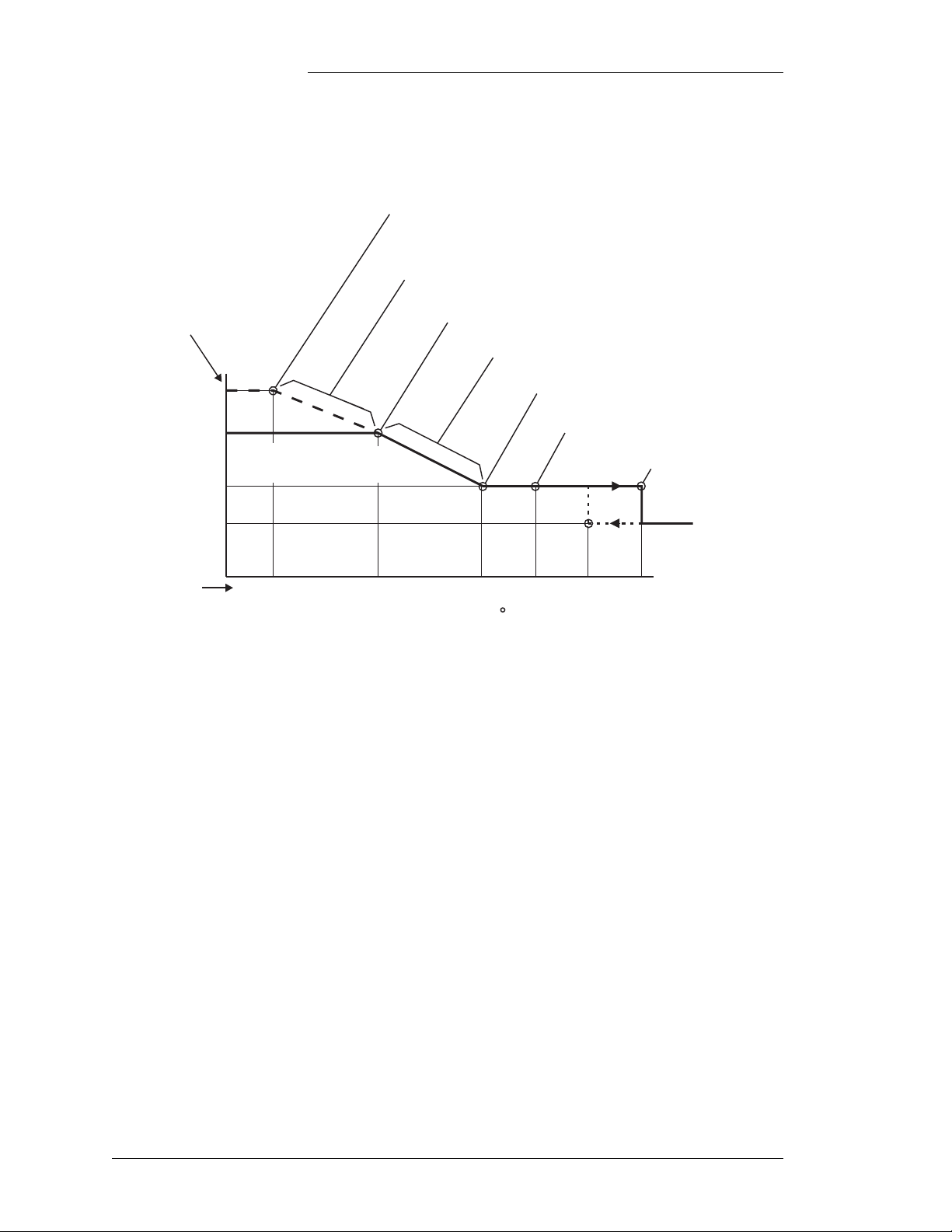
Temperature
Compensation
Voltage Adjustment
(volts per cell)
C(D–A)
•
0
E(F–D)
•
Galaxy Rack-Mounted Vector Controller J85501M-1
A - Battery Low Temperature Voltage
Increase Threshold (-5 to +20 °C)
B - Low Temperature Voltage
Compensation Disabled
B - Battery Low Temperature Compensation
Voltage Increase (Enable/Disable)
C - Battery Low Temperature Voltage
Increase (1mV to 5mV / Cell / °C)
D - Battery Temperature At Which There
Is No Voltage Compansation (15 to 30 °C)
E - High Battery Temperature Decrease
Voltage Rate (1mV to 5mV / Cell / °C)
F - High Battery Temperature Voltage
Decrease Upper Threshold Limit (30 to 55 °C)
G -High Battery Temperature
Alarm Threshold (30 to 85 °C)
H - High Battery Temperature
Step Down At (45 to 85 °C)
1
2
–0.17
Default Settings
Cell Temperature ( C)
1. The Battery High Temperature Alarm occurs when the temperature rises above the High Battery
Temperature Alarm Threshold ( ) set point. It retires when the temperature decreases to 10 °C below
this set point set point (45 °C default).
2. Plant voltage decreases 0.17 volts per cell when the temperature increases above the High Temperature
Voltage Step Down At ( ) set point. It is increased 0.17 volt s per cell when the temperature decreases to
10 °C below this set point, as indicated by the dashed line (65 °C default).
H
G
55 65 7545255
Figure 3-1: Battery Thermal Compensation Set Points
Note: Any time that Battery Thermal Compensation is actively
changing the plant voltage above or below that set by the FSP
parameter during configuration, the LCD indicates the mode by
displaying the message “Float - Compensated”. This is not an
alarm condition, only an indication to the user that plant voltage
is different than that set by the FSP parameter.
Rectifier Sequencing
Rectifier Sequencing is a feature which allows the Vector to
bring the plant rectifiers back on line one at a time following an
ac power interruption. This serves to minimize their impact on
3 - 10 Operation Issue 2 January 2008
Page 39

Galaxy Rack-Mounted Vector Controller J85501M-1
the ac service, especially useful in avoiding loading down an
emergency generator with an inrush surge.
The Reserve Operation (RO) engine signal (closure, available
only on the BUJ1 board) notifies the Vector that a backup engine
is supplying stable ac power to the rectifiers. A certain number
of rectifiers are then started in sequence. The number of
rectifiers which should be on when the engine is in use is
configurable. Refer to Section 4 for details. The number of ON
rectifiers is usually determined by the capacity of the engine.
When a rectifier reports an ACF to the Vector, it places that
rectifier into standby. As rectifiers report good ac, they are
turned on at 1 second intervals. When the controller senses the
RO signal, it pauses 10 seconds and starts the configured number
of rectifiers at 1 second intervals.
While RO is active, the Vector maintains the configured number
of rectifiers on. When RO retires, the Vector turns the remaining
rectifiers on at 1 second interval.
Shunt Types and Sizes
The Vector provides three separate methods and up to two
separate shunt signals for use in determining the plant current to
display. The access connections to the two shunt signals are
Shunt1+/- and Shunt2+/- as shown in Figure 2-5. These signals
shall be a maximum of 50 mV signals that can represent a range
of 0-9999 amps. Refer to the configuration section of this
manual for additional details.
Float Mode Controls and Thresholds
Float mode is the default mode of operation and is active if the
Boost mode is not active. Plant voltage, while in Float mode, is
determined by the configuration parameter System Float Set
Point (FSP), and may be adjusted by the Battery Thermal
Compensation feature, if it is enabled. There is no individual
adjustment of plant rectifiers in this digital serial bus interface
arrangement. Load share among plant rectifiers is automatic in
all system modes and takes effect within several seconds of a
new rectifier being added to the bus and turned on.
The FSP chosen should correspond to the battery type used and
the battery manufacturer’s recommendations. For example,
Lineage Power KS20472 Round Cell (flooded) battery floats at
2.17 volts per cell (VPC). A 12 cell, 24V plant would therefore
have a FSP of 2.17 x 12 = 26.04V. The Lineage Power KS23619
Issue 2 January 2008 Operation 3 - 11
Page 40

Galaxy Rack-Mounted Vector Controller J85501M-1
Enhanced VR (Valve regulated) battery floats at 2.27 VPC, if
Battery Thermal Compensation is enabled or 2.25 VPC if used
without Battery Thermal Compensation. A 12 cell, 24V plant
using this battery would have a desired FSP of 2.27 x 12 =
27.24V with or 2.25 x 12 = 27.00V without Battery Thermal
compensation.
Rectifier Current Limit in Float mode (FCL) is an adjustable
configuration parameter from 30% to 110% of rectifier capacity.
This parameter can be important in limiting the recharge current
available following a deep discharge in a plant using a “sealed”
or valve-regulated battery type to a level which is safe for that
battery and not cause unnecessary internal pressure buildup and
venting. Typically, this maximum safe recharge rate for “sealed”
or valve-regulated battery types in the industry is in the range of
1/10 of the 8 or 10 hour rating. Refer to your specific battery
manufacturer for recommendations regarding the battery type
used. The following typical example shows the use of the FCL
feature to maintain the maximum recharge rate decided upon.
Consider a plant with three strings of 2VR375E Lineage Power
KS23619 Enhanced VR Series batteries, four 100A rectifiers
and a 200 amp typical load. When ac power returns following a
significant discharge, 200 amps are available for recharging
these batteries, a rate of 67A per string (200A / 3 strings).
Recharge should be limited to approximately 40A per string
(1/10 of 375) however, reducing the possibility of venting and
life depreciation of the batteries. Calculate current limit for
limiting recharge to 40A per string as follows:
CL = [Plant Load + (Max Recharge per String × # Strings) /
(Rect Cap × # Rect) ] × 100
CL = [ 200 + (40 × 3) / (100 × 4)] × 100
CL = [(200 + 120) / 400] × 100
CL = (320 / 400) × 100 = 80%
Check for N + 1 redundancy with this CL value with the
following statement:
Plant Load < [Rect Cap × (# Rect - 1) × CL] / 100
200 < [100 × (4 -1) × 80] / 100
3 - 12 Operation Issue 2 January 2008
Page 41

Galaxy Rack-Mounted Vector Controller J85501M-1
200 < [(100 × 3) × 80)] / 100
200 < (300 × 80) / 100
200 < 240
Float mode adjustments are also available for High Float
Voltage Float Threshold which activates the High Float Voltage
(alarm only) minor when exceeded and the High Voltage Float
threshold which activates the High Voltage major alarm and
rectifier shutdown. Battery on Discharge Float Threshold and
Very Low Voltage Threshold are additional Float mode
configuration parameters. Refer to the Alarm Descriptions
section for additional information regarding these alarms.
Battery Recharge
Current limit
Battery Discharge
Tes t
The battery recharge current limit feature enables the Vector
Controller to limit the recharge current flowing into a battery
section during the charge cycle. This feature is available only in
plants that have at least one battery shunt to monitor the battery
current. It can be enabled or disabled using the front panel
display or EasyView® Interface. The recharge current flowing
into the battery section can be limited to any value between 10
and 1000A.
The Vector Controller can monitor up to two shunts connected
to two battery sections, each battery section can contain one or
more battery strings. The controller limits the current flowing
through the shunts thereby limiting the charging current into the
batteries. This feature has no impact on the discharge current
flowing from the battery. The controller maintains the recharge
current within 10% of the set level.
The purpose of the test is to verify the battery capacity connected
to the plant. The reserve time can be predicted after the test and
stored in the memory for future retrieval. By discharging about
20% of the battery capacity, the controller can predict the total
reserve time if 100% battery capacity is discharged at the same
load condition.
This function can be enabled in the configuration process by
enabling the battery test in the appropriate configuration menu.
Refer to Section 4 for detail. If the function is enabled, this test
can be activated by accessing the operations menus and
manually pressing the Battery Test Start softkey. The battery test
can be stopped in the same manner, by pressing the Battery Test
Start softkey again during the test.
Issue 2 January 2008 Operation 3 - 13
Page 42

Galaxy Rack-Mounted Vector Controller J85501M-1
Note: The battery type should be configured before starting. The
Vector assumes one type of battery per system. The battery type
may be configured as either valve regulated or flooded.
During the test, rectifiers are set at a lower voltage. The set
voltage is the maximum of {LVD1 threshold +ΔV, the LVD2
threshold +ΔV, or EDV}, where EDV (the end voltage) = 22V
for 24V plant and 44V for 48V plant, ΔV = 0.6V for 24V plant
and 1.2V for 48 plant. The plant mode is returned to float mode
automatically if this set voltage is reached during the test.
The test stops automatically whether it is successful or not. Refer
to the configuration process in Section 4. During the test, the
default screen of the LED indicates a battery test is active. Any
alarm occurring during the test aborts the test, and causes the
system to return to float mode.
The last test results, battery reserve time, and load current are
stored in memory. The user can retrieve them under the
operations menu. Refer to the configuration process in Section 4.
Boost Mode Controls and Thresholds
Boost mode is a feature of the Vector which allows the user to
temporarily raise the system voltage to a higher, predetermined
level for a specified period of time. This feature may be useful in
systems using a flooded battery type where the batteries are
displaying symptoms of an undercharged state such as differing
cell voltages or in the case of the Lineage Power KS20472
Round Cell, lead-sulfate crystals visible on the vertical positive
plate columns. Boost mode may also be used to accelerate the
recharge of discharged strings to their full charge condition.
Plant voltage, while in Boost mode, is determined by the
configuration parameter Plant Boost Set- Point. Refer to “Plant
Boost Mode Settings” in Section 4. Like Float mode, there is no
individual adjustment of plant rectifiers. Load share among plant
rectifiers is automatic.
Boost voltage is determined from the battery manufacturer’s
recommendations, but must also be less than the maximum
voltage rating of all connected loads since Boost Mode raises the
entire system bus voltage. Typical boost levels and durations
used might include 2.25 VPC for 96 hours, 2.27 VPC (volts per
cell) for 72 hours, or 2.30 VPC for 48 hours. Do not exceed the
maximum voltage rating of any connected load.
3 - 14 Operation Issue 2 January 2008
Page 43

Galaxy Rack-Mounted Vector Controller J85501M-1
Boost is typically not used with “sealed” or valve regulated
battery types. If it is used, it is generally completed at
significantly lower levels than that of flooded battery design to
avoid the build up of pressure and venting noted under the Float
mode section on Float Current Limit. When Boost mode is
disabled in the configuration menu, the feature cannot be
initiated.
Once enabled, Boost mode is entered by accessing the
operations menu and pressing the Boost softkey. The default
LCD screen shows that the system is in Boost mode of operation.
The present Boost duration is also displayed in hours. This Boost
duration can be edited with 0 and 24 hour minimum and
maximum values (0 = forever). Pressing the Step Boost mode
softkey returns the system to the Float mode. If a High Voltage,
High Float Voltage or RFA alarm occurs while in Boost mode,
the plant returns immediately to Float mode. AC Fail and Phase
Fail alarms does not affect Boost mode.
Boost mode has its own configuration parameters for Rectifier
Boost Current Limit, High Float Voltage Boost Threshold, and
High Voltage Boost Threshold, all of which control these
respective features and alarms whenever Boost mode is active.
Auto Timed Boost
The plant goes into Boost mode automatically if the following
conditions occur:
• Auto Boost is enabled
• Autoboost factor is configured from 1 to 9.
• A battery on discharge alarm occurs with AC Failure alarms,
or rectifier phase alarms occur for at least four minutes.
When all rectifier phase and AC Failure alarms retire, the plant
automatically goes into boost mode.
The duration of the boost period is BD and AC Failure or Phase
alarm duration multiplied by the autoboost factor. The
maximum boost duration is limited to 24 hours.
If AC Failure alarms and Phase alarms are asserted while the
plant is in autoboost mode, the plant re-enters float mode,
retaining the remaining boost duration. If the Battery on
Discharge (BD) alarm asserts while the AC Failure or phase
alarm is active, the new multiplied time is be added to the boost
Issue 2 January 2008 Operation 3 - 15
Page 44

Galaxy Rack-Mounted Vector Controller J85501M-1
duration. When the AC Failure and Phase alarms retire, the plant
re-enters the boost mode for the remaining boost duration.
During autoboost, if the plant has a High Voltage, High Float
Voltage, or RFA alarm, the plant returns to float mode and the
remaining autoboost time is cancelled.
Plant
Battery/Generator
Tes t (P BT )
Remote Access and
Monitoring
Plant Battery Test is a simple battery test feature available with
the Vector controller. When the controller receives a PBT signal
(either via an external input signal or via setting S1-7 to position
1), all the rectifier output voltages are reset to 22V/44V so that
the batteries are placed on discharge. The plant voltage will drop
to only 22V/44V minimum, but remain at this voltage until the
PBT signal is released.
Vector does not reset the output voltage to 22V/44V, even if the
PBT signal is asserted, if there are any active major alarms or if
the serial communication alarm is active. If any major alarm
occurs during the test, the plant recovers to float mode and sets
all rectifiers back to the previous float setting.
The Vector controller offers local and remote (modem or
Gateway) access capability to communicate and configure a
limited set of features using personal computers. It is possible to
communicate with the Vector controller by two means:
• By using any ANSI (American National Standards Institute)
character-based terminal including terminal emulators into
either local or modem ports or by using a PC Telnet
communication session via a TCP/IP LAN connection and a
Gateway card. The T1.317 command language is the human
to machine interface used for this communication. Refer to
Appendix-A for modem and Gateway details.
• By using Galaxy EasyView, which combines both a
communications package and a user friendly Microsoft
Windows interface (local or modem ports only).
The Vector controller provides one remote access port. This port
is split to two RS232 ports on the BUJ1 through digital switches.
These two ports are J4 (DB9) for local terminal access, and J5
for modem or TCP/IP access to the Vector controller. This local
port is referenced to the battery side of the power system.
Connecting non-isolated (earth ground referenced) terminal
equipment may cause damage. Laptop computers running on
battery can typically be connected to the local port. AC line
powered terminals as well as some AC/DC supplies for
3 - 16 Operation Issue 2 January 2008
Page 45

Galaxy Rack-Mounted Vector Controller J85501M-1
computers and laptops are referenced to earth ground. For these
applications isolation is required between the terminal device
and the controller's local port.
J4 connection takes precedence over J5. When a terminal is
connected to J4 communication to/from J5 will be disconnected.
Only when the terminal is disconnected from J4 will
communication to/from J5 resume. J5 connection interfaces with
either the BSM3 (which provides modem and RS-232 Access),
or the BSM4 (which provides isolated RS-232 interface to the
Vector), or with the Gateway card (EBW1) for TCP/IP access.
See Appendix A.
Once logged into the controller, users type in commands to
access measurements, configuration and control parameters in
the system. The command line interface used for incoming
connections is a version of T1.317 adapted for low end
controllers. Two levels of security, User and Super-user, are
provided to protect incoming access and to prevent any
unauthorized access.
The controller can be configured to dial out on alarm and dial out
when all alarms are cleared using the internal modem. The port
settings, configuration and command language used for remote
access as well as the error messages is described in the
Appendices A and B.
Remote Rectifier
Standby
The rectifiers can be placed in standby after accessing them
through the local port or through a modem. Once the rectifier is
placed in standby, it automatically recovers from this state when
the plant voltage drops below the BD threshold level, when the
active rectifiers cannot supply the plant demand.
Dial-out On Alarm This function requires an optional BSM3 modem card. See
Appendix A for description. By default, the controller is
configured not to dial-out at all. It can be configured to dial-out
to a primary phone number or an alternate phone number, used
if the controller fails connect to the primary phone number. The
controller attempts to dial-out when an alarm occurs that it has
not reported yet and when all alarms clear.
Phone numbers may be up to 25 characters long and may contain
any of the following characters: 0123456789,( )#* or space.
Configuring the phone numbers enables the controller to dialout. The phone number must be the number of a modem. After
the controller connects to the remote modem it sends an alarm
Issue 2 January 2008 Operation 3 - 17
Page 46

Galaxy Rack-Mounted Vector Controller J85501M-1
report. The alarm report is the same report generated by the
T1.317 “ala” command with addition of the site id at the
beginning of the report.
When attempting to dial-out, the controller first attempts to dial
the primary phone number. It makes up to three attempts, at 1minute intervals, to connect to the primary phone number. If
unsuccessful, the controller makes up to three attempts, at 1minute intervals, to connect to the alternate phone number. If
still unsuccessful, the controller waits for 15 minutes and then
repeats this cycle. The controller attempts the cycle 6 times
before giving up completely. If the controller successfully
contacts either the primary or alternate phone number it sends
the alarm report and then disconnects.
Whether or not the controller successfully connects with the
primary or alternate phone number, it makes a new attempt to
dial-out when a new alarm occurs or all active alarms clear.
The alarm report includes the site ID followed by all active
alarms in the system or the message NO ALARMS if no alarms
are active in the system.
3 - 18 Operation Issue 2 January 2008
Page 47

Galaxy Rack-Mounted Vector Controller J85501M-1
4 Installation and Configuration
This section covers the installation and configuration procedures
specific to the J85501M-1 Galaxy Vector controller. This
controller is typically factory wired and assembled in an FMS
series battery plant equipped with serialized RS-485 bus
communication rectifiers. It is also available stand-alone for use
with J85702H-1 PXS shelves, NP shelves, etc. Follow the
installation instructions of the appropriate plant, rectifier,
converter and battery products to complete all external wiring
related to those components of the system.
Wiring Refer to Section 2 for a summary of all input/output connections
associated with the J85501M-1 Vector. The digital serial bus
connection must be established from the BUJ1 board port to the
rectifiers.
Internal cabinet monitoring is factory wired to the appropriate
alarm input terminations. They are also available for connection
in the field.
PMJ, PMN, BD, HV/2ACF/VLV, ACF, and MJF alarm output
connections are provided on the 848725383 alarm terminal
board attached to the BUJ board, as described in Section 2 of this
manual. Refer to Figure 2-7 and Table 2-J for additional details.
If use of the available Low Voltage Disconnect (LVD) circuits
is required, the wiring from the LVD1/LVD2 terminals on the
BUJ board or alarm terminal board to the associated driver
circuit, and associated wiring from this driver circuit to the Low
Voltage Battery Disconnect or Low Voltage Load Disconnect
must be completed. A contactor driver circuit is not necessary
when driving less than three contactors from and LVD control
Issue 2 January 2008 Installation and Configuration 4 - 1
Page 48

To J13 (LVD1)
or J14 (LVD2)
Tyco Connector
HSG # 794657-4
As and alternate to connecting to
J13 or J14, connections may be
made to the Alarm Termination board.
LVD1 LVD2
TB3-4
TB3-5
TB3-6
TB3-7
TB3-9
TB3-10
TB3-11
TB3-12
3
1
4
2
Galaxy Rack-Mounted Vector Controller J85501M-1
output. For these applications the contactor may be wired
directly to the control output of the BUJ board. The installation
of this circuitry is covered in the appropriate plant product
manual. These connections are typically factory wired. If the
controller is to be wired in the field, the following connections
should be made to the external LVD contactor from the alarm
terminal board.
Battery Charge BusBattery Disharge Bus
LVBD
Contactor
2A
Contactor Coil
Note: Contactor DC coil is polarity sensitive.
To DG Bus
To DG Bus
(To Rectifiers)(To Batteries)
Contactor Sense Switch
Closed when contactor is open.
Up to 3 contactors can be
daisy chained per LVD output.
Size wires accordingly.
Figure 4-1: Typical Wiring for LVD Contactors (LVBD Shown)
Alarm
Signal
Board
LVD1_ST(ate) TB3.4 J13-2 A closure between this signal and LVD1_RTN or bat, signals the
LVD1_RTN TB3.5 J13-1 Return for LVD1_ST
LVD1_CON1 TB3.6 J13-3 Provides on side of a contact closure for contactor coil operation
LVD1_CON2 TB3.7 J13-4 Provides second side of a contact closure for contactor coil operation
LVD2_ST(ate) TB3.9 J14-2 A closure between this signal and LVD1_RTN or bat, signals the
LVD2_RTN TB3.10 J14-1 Return for LVD1_ST
LVD2_CON1 TB3.11 J14-3 Provides on side of a contact closure for contactor coil operation
LVD2_CON2 TB3.12 J14-4 Provides second side of a contact closure for contactor coil operation
6-Pin
Connector
Description
Vector controller the Contactor is OPEN.
Vector controller the Contactor is OPEN.
If the plant batteries are the “sealed” or maintenance free valveregulated type, Battery Thermal Compensation may be used.
This feature requires 10K ohm thermistor devices. The Vector
controller can monitor up to four temperatures. If more than four
devices are needed, a 210E thermistor multiplexer may be used.
The 210E is then wired into the BUJ1 temperature ports as
shown in Figure 2-5. The installation of this equipment is
4 - 2 Installation and Configuration Issue 2 January 2008
Page 49

Galaxy Rack-Mounted Vector Controller J85501M-1
covered in its respective product manual. These connections
may be factory or field wired.
Thermistor input and alarm connections for the 210E thermistor
multiplexer unit are shown in Figure 4-2.
The Vector performs rectifier sequencing based on the state of
the ACF alarms from the rectifiers and Rectifier RO (Reserve
Operation) engine signal terminated at the BUJ1 RO terminal. If
this feature is to be used, complete this wiring as described in
Section 3.
210E
µP Fail Maj
LED Test
Ω Out
Open/Shorted
Probe
BUJ1 with GCM2/3
J1
1
2
BK
G
Temperature Port
RTH ALM
RTH ALMR
Temperature Alarm
Ground
3
Min
4
5
6
J4
O
R
BR
848302048 Cable Set
4
6
RTHn+
RTNn
ENn
Probe Signal +
Probe Signal –
Probe Present
n = 1 to 4
These two connections are only required
if it is desirable to have the 210E Power
Minor Alarm (PMN) give a Temperature
Probe Alarm (TPA) for thermistor number 1.
Figure 4-2: 210E Thermistor Multiplexer Connections to BUJ1
Front Panel Operation
Default Front Panel Menu
The J85501M-1 Galaxy Vector Controller with its LCD display
presents a default front panel screen displaying the system bus
voltage and load current. Regardless of the active display mode,
if no key is pressed for approximately 3 minutes, the Vector
returns to its default menu. The present operating state of the
system is also displayed on the default menu.
Issue 2 January 2008 Installation and Configuration 4 - 3
Page 50

Galaxy Rack-Mounted Vector Controller J85501M-1
View Active
Alarms Mode
If alarms are active in the system, the last two rows of the screen
will provide additional softkey information. The third row will
provide a softkey that allows a user to deactivate all audible
alarms. This is performed by using the “ACO” feature. The
fourth row on the display will provide immediate access to the
system alarms. This mode is entered by pressing the View
Active Alarms softkey. While in this mode, alarms are listed in
order of severity. All major alarms will be listed first, followed
by minor alarms. If four or more alarms are present, use the up
or down arrows to scroll through the alarms. When no alarms are
present, the default screen will display No Active Alarms. To
exit View Active Alarms mode, press “Done” the Home key. If
no key is pressed for 3 minutes, the Vector returns to the default
screen automatically.
Configuration All rectifiers must be numbered uniquely. Valid numbers for
rectifiers are 1 through 24. Refer to the appropriate sections of
the plant manuals for setting ID numbers. NP rectifier
numbering is managed through configuration in the shelf. For
additional information, consult the appropriate NP
documentation.
SW1 and Softkey Display Navigation in Configuration Mode
SW1-1 of the BUJ1 board is a hardware enable switch for
Configuration mode of the J85501M-1. If Configuration is not
enabled, the user is only permitted to access and view the
configuration parameters, but may not change any of them. To
allow configuration changes, move SW1-1 to position 0. Once
configuration has been completed, it is a good practice to disable
(position 1) SW1-1 to prohibit someone from mistakenly
changing these parameters.
Configuration mode is entered by pressing the Home key to
display the menu selections. Press the appropriate softkey to
enter the Configuration mode. The first parameter of the
configuration menu will be displayed. Refer to Table 4-A for a
description of the parameters of the configuration menu. Note
that two columns of default values are shown, for standard and
custom applications. The defaults are determined by SW1-2.
SW1-2 = 0 is standard, SW1-2 = 1 is custom. SW1-2 is
recognized only upon power-up of the GCM.
In addition, the other remaining switches on SW1 (see Figure 2-
5) are used to configure the installed option card, the installed
rectifier class, and alarm setting for alarm contacts
4 - 4 Installation and Configuration Issue 2 January 2008
Page 51

Galaxy Rack-Mounted Vector Controller J85501M-1
HV/2ACF/VLV. If no option card is installed, set S1-3 to the
factory default of “0”. This will allow local terminal access. The
GPS rectifier class includes all 596 and 595 series of serial
controlled rectifiers (S1-4=0). NP rectifiers include NP2500,
NP1500, NP1200, and NP1300 with installed NPC1 GP serial
communication option cards (S1-4=1). The alarm select switch,
S1-5, can be changed and recognized while the GCM is
powered. Similarly, S1-7 can be recognized while the GCM is
powered and setting this switch to “1” will manually force a PBT
session. S1-6 is used to initiate the front panel display when the
display assembly has been removed and re-installed. S1-8 is
used to initiate the front panel display when the display assembly
has been removed and re-installed.
Once in configuration mode, use the ∧ and ∨ keys to select the
heading that contains the item you want to edit See Figure 4-x
for assistance. Press the appropriate softkey on the left to access
the item to be edited. Then use the appropriate arrow keys to
change the default values of the parameters being edited.
Generally the ∧ and ∨ arrows are used to scroll through a
selection of items or used to change a digit in a numerical value.
The < and > arrows are used to move left and right in a
configuration field. Items displayed in brackets identify the
user’s place in the menu structure. For instance, [config 1/3]
means screen 1 of 3 in the Configuration menu.
Once a change is made, two actions are available. The first is to
press the softkey designated “Save.” The new value for the
parameter is saved and will be used from then on. The second
choice is to press the softkey designated “Quit.” The new
parameter is not saved. The previous value is restored as the
system value. Pressing the Menu hardkey has the same effect as
“Quit.” Both of these choices remove the user from the
parameters edit screen.
If an attempt is made to set a parameter higher than allowable,
the maximum value will be displayed. Likewise, an attempt to
set a parameter lower than allowed results in display of the
minimum value.
To save changes made to a parameter value and return to the
configure menu, press the Save softkey. To return to the
configure menu without saving any changes to a parameter,
press the Quit softkey. To exit configuration mode and return to
Issue 2 January 2008 Installation and Configuration 4 - 5
Page 52

Galaxy Rack-Mounted Vector Controller J85501M-1
the default screen, press MENU twice. If no key is pressed for
approximately three minutes, the display will return to the
default front panel screen.
Refer to Table 4-A as each of the Configuration Parameters is
explained in the following sections. Each section also explains
how to access the data available from these features.
Table 4-A: Configuration Parameters
Main Menu
Heading
Float Voltage
Rectifiers
Shunts
Parameter
Description
System float
voltage set point
High float voltage
major alarm
High float voltage
minor alarm
Battery discharge
major alarm
Very low voltage
major alarm
Rectifier output
float current limit
Number of
rectifiers on line
System shunt type Battery, load, none Battery Battery
Shunt 1 current
rating
Shunt 2 current
rating
(24V, 48V Systems)
Range
22-28V, 44-56V 27.24V, 54.48V 27.24V, 54.48V
25-30V, 50-60V 28.24V, 57V 28.5V, 57.0V
25-30V, 50-60V 27.74V, 56V 27.74, 56.0V
23-27.5V, 46-55V 25.54V, 51.1V 25.0V, 51.1V
20-25.5V, 40-51V 23.00V, 46.00V 23.0V, 46.0V
30-110% 100% 110%
1-24 24, 1 24
0-9999A 800A 1000A
0-9999A 0A 0A
Default (24V, 48V Systems)
Standard Custom
4 - 6 Installation and Configuration Issue 2 January 2008
Page 53

Galaxy Rack-Mounted Vector Controller J85501M-1
Table 4-A: Configuration Parameters (Continued)
Main Menu
Heading
Batteries
Parameter
Description
Type Valve-regulated, flooded Valve-regulated Valve-regulated
Battery discharge
test enable
High battery
temperature major
alarm
Battery temperature
compensation
enable
High battery
temperature
stepdown voltage
High battery
temperature voltage
decrease stop
(upper slope limit)
High battery
temperature voltage
decrease rate (upper
slope per cell)
Nominal
temperature (no
voltage
compensation)
Battery low
temperature
compensation
voltage increase
enable
Low battery
temperature voltage
decrease stop
(lower slope limit)
Low battery
temperature voltage
decrease rate (lower
slope per cell)
Battery recharge
current limit enable
Battery recharge
current limit
threshold
(24V, 48V Systems)
Range
Enabled/Disabled Disabled Disabled
30° to 85°C 55°C 75°C
Enabled/Disabled Disabled Enabled
45° to 85°C 75°C 75°C
30° to 55°C 45°C 53°C
1 to 5mV/°C 3mV 3mV
15° to 30°C 25°C 25°C
Enabled/Disabled Disabled Disabled
-5° to 20°C 0°C -5°C
1 to 5mV/°C 3mV 3mV
Enabled/Disabled Disabled Disabled
10-1000A 1000A 1000A
Default (24V, 48V Systems)
Standard Custom
Issue 2 January 2008 Installation and Configuration 4 - 7
Page 54

Galaxy Rack-Mounted Vector Controller J85501M-1
Table 4-A: Configuration Parameters (Continued)
Main Menu
Heading
Contactors
Converters
Boost
Parameter
Description
Contactor 1 type Battery/Load/None None Battery
Disconnect voltage,
contactor 1
Reconnect voltage,
contactor 1
Contactor 2 type Battery/Load/None None N/A, 43.2V
Disconnect voltage,
contactor 2
Reconnect voltage,
contactor 2
Converter set point
voltage
Converter
shutdown voltage
(disconnect
threshold)
Converter
shutdown voltage
enable (low voltage
disconnect)
Converter restart
voltage (reconnect
threshold)
Boost feature
enable
Boost set point
system voltage
High boost voltage
major alarm
threshold
High boost voltage
minor alarm
threshold
Auto boost feature
enable
Auto boost duration
(_ × BD duration)
Manual boost
duration
Boost current limit
(rectifier limit
during boost)
(24V, 48V Systems)
Range
20-26V, 40-52V 21V, 43.2V N/A, 43.2V
20-26V, 40-52V 22.2V, 44.4V N/A, 44.4V
20-26V, 40-52V 21V, 43.2V N/A, 44.4V
20-26V, 40-52V 22.2V, 44.4V N/A, 43.2V
46-57V 50V N/A
20-26V 21V N/A
Enable/Disable Disable N/A
20-26V 22.2V N/A
Enable/Disable Disable Disable
24-30V, 48-60V 27.24V, 55.2V N/A, 55.2V
26-30V, 52-60V 28.24V, 57V N/A, 57.0V
25-30V, 50-60V 27.74V, 56.2V N/A, 56.2V
Enable/Disable Disable Disable
1 to 9 1 N/A, 1
1-250 hours 8 N/A, 8
30%-110% 100% N/A, 100%
Default (24V, 48V Systems)
Standard Custom
4 - 8 Installation and Configuration Issue 2 January 2008
Page 55

Galaxy Rack-Mounted Vector Controller J85501M-1
Table 4-A: Configuration Parameters (Continued)
Main Menu
Heading
Communication
ports
Calibrate to meter
Parameter
Description
Local port baud rate
setting
Local port flow
control setting
Modem port baud
rate setting
Modem port flow
control setting
Number of rings
before modem
answers
Calibrate system
voltage to a new
value
Calibrate converter
voltage to a new
value
Range
(24V, 48V Systems)
Auto/1200 to 19,200 Auto Auto
None/SW/HW None None
Auto/1200 to 19,200 2400 2400
None/SW/HW None None
1 to 9 1 1
22-28V, 44-56V System voltage N/A
46-57V Converter voltage N/A
Default (24V, 48V Systems)
Standard Custom
Battery Discharge
Test Results
After initiating a Battery Discharge Test through the Operations
menu, the user obtains the data or results from a battery
discharge test through the View Status menus. Selecting
Batteries > Battery Test Result displays the result of the last
battery test. The Vector stores the result of the last completed
test. This is the recorded data (not manually changeable) for the
battery test result. Refer to the battery discharge test operation
for detail test procedure and results.
Pressing the Battery Test Result softkey displays an indication
of the last battery test performed. The display indicates either
that the test was completed or not completed. In addition, the last
completed battery test results are saved and can be accessed by
pressing the “< View Completed” softkey. This allows the user
to observe the reserve time and load current during the test. If for
some reason the test was completed and results were
unsatisfactory, the message “Check Battery” is displayed. If the
last test was interrupted, the message “Not Available” is
displayed. If a test was stopped before completion, the phrase
“Previous Test Was Interrupted” will also appear when the
Battery Test softkey is pressed.
Issue 2 January 2008 Installation and Configuration 4 - 9
Page 56

Galaxy Rack-Mounted Vector Controller J85501M-1
When a test has been completed, the battery reserve time is
displayed in the form of hours and tenths of hours (hh.h).
Load current is displayed in the form of Amps without decimal
point (dddd). The load current is the current observed during the
test.
Battery Discharge
Test Enable
Two settings are available, Enable or Disable. Selecting Enable
allows the battery discharge test to be performed and selecting
Disable prevents the battery discharge test from being
performed. Press the < Save softkey to save one of the two
settings. When the test is enabled, the battery test softkey will be
enabled. Otherwise, the battery test softkey is disabled.
Shunt Type/Size The J85501M-1 Vector provides two separate shunt signals for
use in determining the system current to display: SH1+/- and
SH2+/- on the BUJ1 board as shown in Figure 2-5. The shunts
must be rated for 50 mV and have a current rating of 0-9999
amps.
The method used by the Vector to determine the system load
value is determined by the configuration of the Shunt Type. The
three choices for this parameter are “None”, “Load”, and
“Battery”.
None: Select “None” if there is no central load shunt used in the
system or connected to the BUJ1 board. Selecting “None”
results in displaying the system load current as the sum of the
individual rectifier loads. This may not be the true “load” current
in systems with battery backup since it includes the portion of
the rectifier loads which is floating or recharging the batteries.
Zero amps will be shown when the rectifiers are off and the
batteries are carrying the system load. Typically, this shunt type
would be used only in batteryless systems, where this is an
accurate depiction of system load.
Load: Selecting “Load” as the shunt type assumes that the
system provides at least of the two shunt signals to the BUJ1
board. When the shunts are configured for “Load,” the displayed
system load is the sum of all active shunt values. Battery float or
charge current can be determined by subtracting the displayed
system load current from the sum of the individual rectifier
outputs. The use of two separate shunt signals allows loads to
4 - 10 Installation and Configuration Issue 2 January 2008
Page 57

Galaxy Rack-Mounted Vector Controller J85501M-1
two distribution bays to be monitored separately. If the current is
displayed as “Err,” the system may contain a battery shunt or
may be improperly wired.
Battery: Placing one or both shunts in the charge/discharge path
of the system batteries and configuring the shunts as Battery
shunts results in a system load current that is the calculated
difference of the sum of the individual rectifier currents and the
sum of the battery charge currents obtained from the shunt
measurements. This is the typical configuration used with most
distributed architecture systems. It is accurate regardless of
whether system batteries are charging or discharging.
Shunt Size The shunts are assumed to have a voltage rating of 50mV. The
full scale load ratings are user configurable. Each shunt can have
a current rating configured from 1 to 9999 amps. A value of 0000
disables that shunt reading.
System Float
Mode Settings
The following parameters are settings which are active anytime
the plant is in Float mode.
System Float Voltage Set-Point: This is the output voltage that
all system rectifiers will be set to while in Float mode. If Battery
Thermal Compensation is enabled and active, the actual system
voltage will be adjusted from Float Set Point based on the
highest battery temperature monitored by the Vector.
Rectifier Float Current Limit: Rectifier current limit can be
adjusted from 30 to 110% of rectifier capacity. This is the
current limit while the system is in Float mode.
High Float Voltage Major Alarm Threshold: System voltage
monitored above this threshold results in a High Voltage major
alarm and possible rectifier shutdown while in Float mode.
High Float Voltage Float Minor Alarm Threshold: System
voltage monitored above this threshold results in a High Float
Voltage minor alarm (no rectifier shutdown) while in Float
mode.
Battery on Discharge Float Major Alarm Threshold: System
voltage monitored below this threshold results in a Battery
Discharge major alarm while in Float or Boost mode.
Issue 2 January 2008 Installation and Configuration 4 - 11
Page 58

Galaxy Rack-Mounted Vector Controller J85501M-1
Very Low Voltage
Threshold
Battery Recharge
Current Limit
Settings
Battery Thermal
Compensation
Settings
Very Low Voltage Major Alarm Threshold: In any system
mode, system voltage monitored below this threshold results in
a Very Low Voltage major alarm.
Battery Recharge Current Limit: The maximum current
flowing into a monitored battery string during a recharge period
is adjustable to any value between 10A and 1000A. At least one
battery string must be present to have this function.
Battery Recharge Current Limit Enable: To activate the
battery recharge current limit feature, the function must be
enabled in the appropriate configuration menu. The user must
select “enabled;” the default setting is “disabled.”
Refer to Figure 3-1 (standard) or Figure 3-2 (custom) for a
graphical representation of the various Battery Thermal
Compensation settings.
High Battery Temperature Alarm Threshold (G): A
monitored battery temperature above this threshold results in a
Battery Temperature major alarm. This threshold can be set from
30°C to 85°C. The default temperature is 45°C.
High Battery Temperature Step Down Temperature (H): A
monitored battery temperature above this threshold results in a
“step” decrease in plant voltage to a level corresponding to 0.17
volts per cell (VPC) below the Plant Float Voltage Set-Point
(FSP). This threshold can be set from 45°C to 85°C. The default
temperature is 65°C.
Battery Temperature Slope Upper Temperature (F): This is
the upper temperature where Battery Temperature
Compensation will have reduced system voltage to a level
corresponding to F*(F-D)*cells-per-string below the FSP.
System voltage will be reduced proportionally at any
temperature between this point and the No Voltage
Compensation Temperature (D).
Battery No Voltage Compensation Temperature (Nominal
Temperature) (D): This is the zero compensation temperature
point. Temperatures monitored between this point and the High
Battery Temperature Voltage Decrease Upper Threshold (F)
will result in a proportional decrease of plant voltage to a level
corresponding to F*(F-D)*cells-per-string below the limit. If the
4 - 12 Installation and Configuration Issue 2 January 2008
Page 59

Galaxy Rack-Mounted Vector Controller J85501M-1
Low Battery Temperature Compensation is enabled,
temperatures monitored between this point and the Battery Low
Temperature Voltage Increase Threshold (A) will result in a
proportional increase of plant voltage to a level corresponding to
C*(D-A)*cells-per-string above the limit.
Battery Low Temperature Voltage Increase Threshold (A):
This is the lower temperature where, if Battery Low
Temperature Compensation is enabled, the temperature
compensating feature will have increased system voltage to a
level corresponding to C*(D-A)*cells-per-string above the FSP.
System voltage will be increased proportionally at any
temperature between this point and the Nominal Battery
Temperature (D) Slope.
Battery High Temperature Voltage Decrease Rate (Slope)
Per Cell (E): This is the slope rate for the voltage decrease per
cell when the battery temperature is above the Nominal Battery
Temperature (D) Slope.
Battery Low Temperature Voltage Increase Rate (Slope) Per
Cell (C): This is the slope rate for the voltage increase per cell
when the battery temperature is below the temperature at which
there is no voltage compensation (Nominal Temperature, D).
Battery Low Temperature Voltage Compensation Increase
Enable: This feature must be enabled in the appropriate
configuration menu in order to compensate at the lower
temperatures. This feature increases plant voltage rather than
decreasing it based on temperature. The capability to enable this
feature separately from high temperature compensation is
provided so that equipment loads sensitive to high voltages can
be protected.
Battery Temperature Compensation Enable: Battery
Temperature Compensation (slope thermal compensation) must
be configured to “enabled” in order for the feature to be active.
Issue 2 January 2008 Installation and Configuration 4 - 13
Page 60

Galaxy Rack-Mounted Vector Controller J85501M-1
Low Voltage
Disconnect
Contactor 1 and 2
Settings
Contactor 1 and 2 Low Voltage Disconnect jumpers: Six
jumpers are associated with the LVD circuitry on the BUJ board:
three of these jumpers J11, J12 and J15 are for LVD1 circuitry
and three jumpers J18, J19, and J20 are for LVD2 circuitry. J11,
J12, J18, and J19 are factory set, but should the BUJ need to be
replaced, these jumper positions should be verified as being set
to the appropriate plant voltage as marked on the PWB (24 or
48V). J15 for LVD1 and J20 for LVD2 are manual LVD forceon jumpers used when it is required that the contactors remain
closed during service. Return to the Auto position for normal
operation.
Contactor 1 and 2 Low Voltage Disconnect Threshold: The
low voltage at which a signal will be sent to the respective
contactor driver circuit, causing it to open, disconnecting either
the load or the batteries, depending on the contactor’s location in
the circuit.
Contactor 1 and 2 Reconnect Voltage Threshold: This is the
voltage at which a signal will be sent to the respective contactor
driver circuit, to force the contactor to reconnect or close. This
can be used to reconnect either loads or batteries, depending on
the contactor’s configuration within the system.
Plant Boost Mode
Settings
Contactor 1 and 2 Type: The contactor type defines how the
contactor is used in the system. The type can be set to one of
these three choices:
None no contactor available
Load contactor used for connecting a load
Battery contactor used to connect/disconnect
battery strings
The following configuration parameters are settings which are
active anytime the plant is in Boost mode.
System Boost Set-Point: This is the voltage that all system
rectifiers will be set to when the Boost mode is entered.
Rectifier Boost Current Limit: This is the current limit of the
rectifiers while in Boost mode. This current limit is adjustable
from 30% to 110% of rectifier capacity.
High Voltage Boost Threshold: System voltage monitored
above this threshold results in a High Voltage major alarm. The
controller attempts to shutdown the offending rectifiers.
4 - 14 Installation and Configuration Issue 2 January 2008
Page 61

Galaxy Rack-Mounted Vector Controller J85501M-1
High Float Voltage Boost Threshold: A voltage monitored
above this threshold results in a High Boost Voltage alarm. No
rectifier shutdown attempts are made.
Boost Auto Enable: This function enables and disables the auto
boost feature. The parameter must be configured to “enabled”
for this feature to be available.
Boost Enable: This function enables and disables the manual
timed Boost feature. The parameter must be configured to
“enabled” for this feature to be available.
Boost Auto Mode Factor: This factor sets the duration of the
boost. A value from 1 to 9 sets the factor that determines how
long the plant is in boost mode after a discharge. The time is
determined by multiplying the BD duration by this factor. The
Boost Enable parameter must be enabled for this feature to be
available.
Converter
Settings
The following configuration parameters are settings which
affect the operation of any converters that may be connected to
the system and communication on the serial bus.
Converter Voltage Set-Point: This is the output voltage that all
converters will be set to by Vector.
Converter Low Voltage Disconnect Enable: This feature
allows the converter LVD to be operational. Select “Enabled” in
the configuration menu to enact the function.
Converter Low Voltage Disconnect Threshold: This is the
value at which the converters are placed into standby.
Converter Low Voltage Reconnect Threshold: This is the
value at which the converters are retired from standby and their
outputs returned to the set-point.
Converter Front Panel Voltage Calibration: The voltage
displayed on the front panel is the uncalibrated converter output
voltage as seen by the controller. If necessary, this voltage can
be calibrated to match a meter. Adjust the displayed voltage until
it matches the voltage displayed on a calibrated voltmeter that is
measuring the voltage across the converter’s output.
Issue 2 January 2008 Installation and Configuration 4 - 15
Page 62

Galaxy Rack-Mounted Vector Controller J85501M-1
Voltage
Calibration
Reserve
Operation Engine
Controller’s displayed system voltage may be adjusted or
calibrated to a known, calibrated meter.
Caution:
This calibration affects all controller functions using plant
voltage and/or current values. These functions include the
float and boost set points. Generally, this feature is not
necessary.
Front Panel Voltage Calibration: The displayed value of
voltage can be adjusted by going through the configuration
menu. Under “Calibrate to meter,” the “System Voltage” softkey
can be used to adjust the system of the system voltage. Adjust the
displayed voltage until it matches the voltage displayed on a
calibrated voltmeter measuring the plant or converter output
voltage.
Number of Rectifiers On With Backup Engine (Reserve
Operation Engine): When a backup engine is running to supply
ac power to the rectifiers, a certain number of rectifiers in the
system are allowed to be turned on. This number should be based
on the engine capacity. The number can be selected between 1
and 24. The default number is 24 (maximum rectifiers on).
Serial Bus
Updating and
Clearing
The user can perform several operations under the
Control/Operations softkey in the Main Menu. These operations
include Start Battery Test, Star Lamp Test, Updating the Serial
Link, and Starting Boost. Brief descriptions of these items
follow:
The Vector remembers any rectifier or converter connected to
the system’s digital serial bus. A Rectifier Fail Alarm (RFA) will
be active if any one of these components is removed from the
system or if communication is lost between the component and
the controller. If the controller is indicating Rectifier or
Converter Fail Alarm (RFA) and no alarm is indicated by the
LEDs of the rectifiers or converters, it may be necessary to clear
the Galaxy VC rectifier memory. Operating the Clear Events
(CLE) resets the Vector rectifier memory and tells the controller
to recognize all devices on the bus. The alarm may be cleared.
4 - 16 Installation and Configuration Issue 2 January 2008
Page 63

Galaxy Rack-Mounted Vector Controller J85501M-1
Note: A few moments after executing Clear Vents, the controller
alarms should clear and each rectifier should display no alarms.
If alarms continue to be displayed, see Section 5,
Troubleshooting. USL will not restart the rectifiers or converters
at any time.
Software Release
Information
A report of the present software release active in the control
board microprocessor may be obtained via the
View Status -> Software Version menu path.
Issue 2 January 2008 Installation and Configuration 4 - 17
Page 64

Page 65

Galaxy Rack-Mounted Vector Controller J85501M-1
5 Troubleshooting
Replacing Circuit
Packs
Table 5-A: Replacement Circuit Packs and Temperature Modules
Designation Description Comcode
Checking the
Highest Battery
Temperature
Table 5-A lists the circuit packs available as replacements in the
Vector Controller.
210E Thermal Probe Multiplexer 107789513
BSM3 Modem Board 108415647
BSM4 Local Port Isolation Board 848501037
EBW1 Gateway Network Card 848733898
- EBW Power Cable 848575841
GCM2 24V Vector Control Board 108890088
GCM3 48V Vector Control Board 108890096
-- LCD Display / Keypad Assembly 848733907
-- Alarm Board Header 406790188
1U-ALM Alarm Termination Board 848711933
-- P5 Power Cable 848722096
If temperature probes are connected to the controller and thermal
compensation is enabled, the highest battery temperature can be
calculated based on the plant voltage. Temperatures between the
battery thermal lower temperature and the battery thermal
nominal temperature can be calculated if the raising of system
voltage is also enabled.
Calculate the temperature as follows:
voltage difference =
(system set point – system voltage reading)
cells per string
where cells per string is the number of 2-volt cells per string.
Issue 2 January 2008 Troubleshooting 5 - 1
Page 66

Galaxy Rack-Mounted Vector Controller J85501M-1
If voltage difference ≥ 0.17, the highest battery temperature is at
least as high as the battery thermal step temperature hysteresis
value, which is the battery thermal step temperature – 10°C.
If voltage difference = 0.1, the highest battery temperature is
between the battery thermal upper temperature and the battery
thermal step hysteresis value.
If voltage difference > 0 and voltage difference < 0.10,
temperature = thermal nominal temp + voltage difference ×
(thermal upper temp – thermal nominal temp)
Note: This will be a temperature in the range of the battery
thermal nominal temperature setting and the battery thermal
upper temperature setting.
If voltage difference ≤ -0.10, the highest battery temperature is
at or lower than the battery thermal lower temperature setting.
Inaccurate Plant
Voltage Readings
If voltage difference < 0 and voltage difference > -0.10,
temperature = thermal lower temp – voltage difference ×
(thermal nominal temp – thermal lower temp)
Note: this will be a temperature in the range of the battery
thermal lower temperature setting and the battery thermal
nominal temperature setting.
If the default menu of the LCD indicates that the system is in
“compensation mode,” this indicates that the plant voltage has
been altered to raise or lower based on the highest battery
temperature. Temporarily disabling the Battery Thermal
Compensation feature through the configuration menu returns
the system voltage to the set point.
The system voltage may differ slightly from an external meter
reading. This difference could be attributed to the calibration or
accuracy of the external voltmeter. A meter adjustment may be
attempted by using the “Calibrate to meter” function in the
Configuration menu. See to the plant voltage configuration
section.
If the voltage sense wires are open or reversed, the display will
be +16 or -35 depending on the GCM type.
5 - 2 Troubleshooting Issue 2 January 2008
Page 67

Galaxy Rack-Mounted Vector Controller J85501M-1
Temperature
Probe Alarm is
present
Unexplained
Rectifier Failure
Alarm and
Multiple Rectifier
Failure Alarm
The Temperature Probe Fail alarm indicates that either there is
something wrong with the temperature connections, or that there
is a problem with one of the external temperature processing
units. An additional possibility is that the alarm is indicating that
the thermal compensation feature is enabled, and that no
temperature probes are present. If there are no temperature
probes connected to the Vector, then disable the Battery Thermal
Compensation Enable setting.
A rectifier that is removed from the plant will generate a
Rectifier Fail Minor alarm. If more than one rectifier is missing,
a Multiple Rectifier Fail Major alarm is generated. To clear these
alarm conditions, go to the Operation Menu and assert the Clear
Events (CLE) command.
Note: A few minutes after executing the Clear Events function
to clear alarms, the controller RFA alarm should clear and no
rectifier should display any alarms. If alarms continue to be
displayed, continue investigating the system for possible
rectifier problems.
Unexplained
Converter Failure
Alarm and
Multiple
Converter Failure
Alarm
Rectifier Id
conflict alarm is
asserted
Converter Id
(Cid)
A converter that is removed from the plant will generate a
Converter Fail Minor alarm. If more than one converter is
missing, a Multiple Converter Fail Major alarm is generated. To
clear these alarm conditions, go to the Operation Menu and
assert the Clear Events (CLE) command.
Note: A few minutes after executing the Clear Events function
to clear alarms, the controller CFA alarm should clear and no
rectifier should display any alarms. If alarms continue to be
displayed, continue investigating the system for possible
converter problems.
This alarm indicates that a rectifier Id has not been set or is
duplicated in the system. Verify all rectifiers are numbered
uniquely between 1 and 24. Refer to numbering procedure in
rectifier manual.
This alarm indicates that a converter Id has not been set or is
duplicated in the system. Verify all converters are numbered
uniquely between 1 and 8. Refer to numbering procedure in bay
manual.
Issue 2 January 2008 Troubleshooting 5 - 3
Page 68

Page 69

Galaxy Rack-Mounted Vector Controller J85501M-1
6 Product Warranty
A. Seller warrants to Customer only, that:
1. As of the date title to Products passes, Seller will have the right to
sell, transfer, and assign such Products and the title conveyed by
Seller shall be good;
2. During the warranty period stated in Sub-Article B below, Seller’s
Manufactured Products (products manufactured by Seller), which
have been paid for by Customer, will conform to industry standards
and Seller’s specifications and shall be free from material defects;
3. With respect to Vendor items (items not manufactured by Seller),
Seller warrants that such Vendor items, which have been paid for by
Customer, will be free from material defects for a period of sixty
(60) days commencing from the date of shipment from Seller’s
facility.
B. The Warranty Period listed below is applicable to Seller’s Manufactured
Products furnished pursuant to this Agreement, commencing from date
of shipment from Seller’s facility, unless otherwise agreed to in writing:
Warranty Period
Product Type New Product Repaired Product*
Central Office
Power Equipment
*The Warranty Period for a repaired Product or part thereof is six (6) months
or, the remainder of the unexpired term of the new Product Warranty Period,
whichever is longer.
C. If, under normal and proper use during the applicable Warranty Period,
a defect or nonconformity is identified in a Product and Customer
notifies Seller in writing of such defect or nonconformity promptly after
Customer discovers such defect or nonconformity, and follows Seller's
instructions regarding return of defective or nonconforming Products,
Seller shall, at its option attempt first to repair or replace such Product
without charge at its facility or, if not feasible, provide a refund or credit
based on the original purchase price and installation charges if installed
by Seller. Where Seller has elected to repair a Seller’s Manufactured
Product (other than Cable and Wire Products) which has been installed
by Seller and Seller ascertains that the Product is not readily returnable
for repair, Seller will repair the Product at Customer’s site.
With respect to Cable and Wire Products manufactured by Seller which
24 Months 6 Months
Issue 2 January 2008 Product Warranty 6 - 1
Page 70

Galaxy Rack-Mounted Vector Controller J85501M-1
Seller elects to repair but which are not readily returnable for repair,
whether or not installed by Seller, Seller at its option, may repair the
cable and Wire Products at Customer’s site.
D. If Seller has elected to repair or replace a defective Product, Customer
shall have the option of removing and reinstalling or having Seller
remove and reinstall the defective or nonconforming Product. The cost
of the removal and the reinstallation shall be borne by Customer. With
respect to Cable and Wire Products, Customer has the further
responsibility, at its expense, to make the Cable and Wire Products
accessible for repair or replacement and to restore the site. Products
returned for repair or replacement will be accepted by Seller only in
accordance with its instructions and procedures for such returns. The
transportation expense associated with returning such Product to Seller
shall be borne by Customer. Seller shall pay the cost of transportation of
the repaired or replacing Product to the destination designated by
Customer.
E. Except for batteries, the defective or nonconforming Products or parts
which are replaced shall become Seller's property. Customer shall be
solely responsible for the disposition of any batteries.
F. If Seller determines that a Product for which warranty service is claimed
is not defective or nonconforming, Customer shall pay Seller all costs of
handling, inspecting, testing, and transportation and, if applicable,
traveling and related expenses.
G. Seller makes no warranty with respect to defective conditions or
nonconformities resulting from actions of anyone other than Seller or its
subcontractors, caused by any of the following: modifications, misuse,
neglect, accident, or abuse; improper wiring, repairing, splicing,
alteration, installation, storage, or maintenance; use in a manner not in
accordance with Seller’s or Vendor’s specifications or operating
instructions, or failure of Customer to apply previously applicable Seller
modifications and corrections. In addition, Seller makes no warranty
with respect to Products which have had their serial numbers or month
and year of manufacture removed, altered, or experimental products or
prototypes or with respect to expendable items, including, without
limitation, fuses, light bulbs, motor brushes, and the like. Seller’s
warranty does not extend to any system into which the Product is
incorporated. This warranty applies to Customer only and may not be
assigned or extended by Customer to any of its customers or other users
of the Product.
THE FOREGOING WARRANTIES ARE EXCLUSIVE AND ARE IN
LIEU OF ALL OTHER EXPRESS AND IMPLIED WARRANTIES,
INCLUDING BUT NOT LIMITED TO WARRANTIES OF
MERCHANTABILITY AND FITNESS FOR A PARTICULAR PURPOSE.
CUSTOMER’S SOLE AND EXCLUSIVE REMEDY SHALL BE
SELLER’S OBLIGATION TO REPAIR, REPLACE, CREDIT, OR
REFUND AS SET FORTH ABOVE IN THIS WARRANTY.
6 - 2 Product Warranty Issue 2 January 2008
Page 71

Galaxy Rack-Mounted Vector Controller J85501M-1
Appendix
A
BSM3 Modem
Port Settings This section describes the communication port settings for the
Modular Phone Jack
Pin 3 - Tip
Pin 4 - Ring
Communications
BSM3 internal modem, external modem, and RS-232 terminal.
Figure A-1 shows the BSM3 modem board. In addition, set
SW1-3 to “0” for the MODEM option. Figure A-2 shows a block
diagram of connections from the Modem kit to the BUJ board.
To Phone
Line
To Controller
(14 Conductor Cable)
TipRing
6
4
RS-232 Local Port
DS102
DS101
DS100
Yellow
Green
Green
Yellow and Green - Modem Board Not Initialized
(Terminal)
Status LEDs
Carrier Detect (Phone Line Connection)
Modem Board Fail
Modem Board Ok
Figure A-1: BSM3 Modem Board
Issue 2 January 2008 Communications Appendix A - 1
Page 72

Galaxy Rack-Mounted Vector Controller J85501M-1
T& R
Lines
J2, TB101
"A"
"A" or "B" "A" or "B"
J1 "B"
Isolated
RS-232
Terminal
BSM3 Modem BUJ1
J100
Power
24V/48V
Can be connected to an isolated
terminal but J1 of the BSM3 is
preferred.
Digital
Switch
J5 "A"
J4 "B"
J100
Figure A-2: BSM3 Modem Connections Block Diagram
The controller communicates with the BSM3 internal modem
and an external modem at the same communication settings.
These settings are as follows:
baud rate: 2400
data bits: 8
stop bits: 1
parity: none
The controller communicates over the RS-232 terminal interface
using the following settings:
baud rate: 9600 default, auto baud from 1200 to
19200
data bits: 8
stop bits: 1
parity: none
Logging in This section describes how to log into the system. The first step
to logging in is to get to an "ENTER PASSWORD: " prompt.
From a modem, dial into the controller and wait for the modem
to connect. After the modem connects you will be presented with
the log-in prompt. If you don't see the log-in prompt after the
modem connects, you may have to press the ENTER key in
order to see the prompt.
Appendix A - 2 Communications Issue 2 January 2008
Page 73

Galaxy Rack-Mounted Vector Controller J85501M-1
From a terminal connected to the RS-232 port, simply press
ENTER until you are presented with the log-in prompt. The
number of ENTER keys required will depend on the baud rate
you are trying to connect at. The controller will adjust its baud
rate automatically until it recognizes the carriage return
character (ASCII 13) sent by pressing ENTER.
At the "ENTER PASSWORD" prompt type the user or superuser password. The default password for each level of security is
listed below.
lineage default user password
super-user default super-user password
In general, the user and super-user may view any measurement,
configuration, or control parameter. The super-user can also set
configuration and control parameters as well as change system
passwords.
After receiving the correct password, the controller will respond
with one of the following command line prompts:
* user command line prompt
** super-user command line prompt
When these prompts appear the controller is ready to accept
commands. If the port is idle for 15 minutes then the session will
terminated.
Issue 2 January 2008 Communications Appendix A - 3
Page 74

Galaxy Rack-Mounted Vector Controller J85501M-1
BSM4 Isolation Board
Terminal
Figure A-3: BSM4 RS-232 Isolation Board Connections Block Diagram
The BSM4 Isolation Board isolates the RS-232 communication
port of the BUJ from battery voltage. Figure A-3 shows a block
diagram of connections from the BSM4 kit to the BUJ board.
Isolated
J1
RS-232
J100
J3
BSM4
Digital
Switch
"A" or "B"
Data
J5 "A"
Power
J4 "B"
Isolated
Terminal
BUJ1
GCMx
RS-232 Port
Appendix A - 4 Communications Issue 2 January 2008
Page 75

Galaxy Rack-Mounted Vector Controller J85501M-1
Galaxy Gateway Figure A-2 shows the Galaxy Gateway installation and cabling
procedures required in a J85501M-1 Vector controller, including
computer and Galaxy Gateway configuration. Note that only one
mounting position is available for a remote option; either a
Gateway (EBW) or modem (BSM) board.
Operational Note If J5 is connected to an option board (EBV1, BSM3 or BSM4),
then a terminal is connected to DB9 connector J4, the J4 RS-232
connection takes precedence. This will stop the RS-232
communication through J5 until the connection to J4 is removed.
848722096
BUJ Power Cable
CAT5 LAN
Cable
848575841
EBW Power
Cable*
Alarm Termination Board
EBW1 Gateway Board
P1
TB4*
TB2*
848575841 Controller
Interface Cable
P5
P5
POWER
FH1
ABSFUSE
11/3A
J5
J5
RS232
OPT
A32
C32
A1B1C1
8
P2
Black
RS485
J8
2
1
8
HDR1 HDR2
Red
TERMRES
R10
J7
2
1
BUJ Board
FAJ
AMJ
LVD1
LVD2 THERM 2THERM 1
J17
1
J13
1
J20
-+-
FORCE ON
1
1
48V
48V
24V
24V
J9
1
1
J14
J1
J3
+
1
J19
48V
J18
24V
J21
1
OFF
ON
BUZ1
1234567
8
1
S1
0
J4
LOCAL RS232
HDR3
DISPLAY
J6
KEYPAD
J16
1
AUTO
J15
1
48V
FORCE ON
1
24V
TJ2
TJ1
BLK/NEGRO
SHUNT
RED/ROJO
PLANT V
*Power Cable Connections
Red: ABS - TB4 Pin 1,3,5,9 or 11
Black: DG - TB2 Pin 11 or 12
Figure A-4: Installing the Gateway
Preparation The following Network Configuration Parameters must be
obtained from your Network Administrator before starting:
• IP address
• Subnet mask
• Host name
• Gateway IP address
Note: Host and Gateway are optional.
Issue 2 January 2008 Communications Appendix A - 5
Page 76

Galaxy Rack-Mounted Vector Controller J85501M-1
Precautions Note: Before starting, make sure proper ESD precautions are
observed. The ESD grounding termination point is located on
the left front of the unit.
• Wear grounded antistatic wrist straps when handling all
circuit packs. The wrist strap must be in contact with the skin
and is not to be worn over clothing.
• Always consider personal safety. Be aware of the presence of
battery potential in the vicinity of the controller.
• Use only insulated tools.
Verify that no controller related alarms are active on the LCD
display panel. If a controller alarm is active, review the product
manual troubleshooting section or contact Lineage Power
technical support.
Tools/Equipment
Required
Unpacking the
Galaxy Gateway
Before installing and configuring the Galaxy Gateway, the
following tools/equipment are required:
• Flat jeweler’s screwdriver (controller DIP switch setting)
• Small #2 Phillips head screwdriver
• PC with terminal emulation program (example:
HyperTerminal)
• 9 pin male serial interface cable (DB-9 male) to connect to
Galaxy Gateway
• Network interface cable (CAT 5 UTP)
The 848733898 Galaxy Gateway Kit has been inspected, tested
and carefully packed. Examine the shipping carton and all
components for any sign of shipping damage.
1. Check for external damage to the shipping cartons.
2. Remove all parts from shipping cartons.
3. Check the following table and verify that all components
are present.
Appendix A - 6 Communications Issue 2 January 2008
Page 77

Galaxy Rack-Mounted Vector Controller J85501M-1
Item Qty Comcode Description
1 1 108340100
2 1 848281945
3 1 848364865
4 2 408456465
5 1 402244081
6 2 407882141
7 2 845143866
8 1 848589859
9 1 848575841
10 4 408450955
11 8 901377366
12 4 901351239
13 1 848649943
Galaxy Gateway circuit pack
Black insulator (not used)
Millennium Controller interface cable (not used)
Nylon mounting posts (HMSP-TM-10)
Cable tie
Metal standoff (9740-SS-0632)
Screw, PPHM 6-32 x 5/16"
Black insulator
Vector Controller interface cable
Metal standoff (AL-5171-16)
Screw, PPHM M3 x 6mm
Nut, hex 6-32
Mounting bracket
If damage is found and/or components are missing, file a claim
with the carrier if applicable, and notify Lineage Power
Customer Service (See Section 1).
Vector Controller
Configuration
Gateway
Installation for
the J85501M-1
Vector Controller
The physical interface for the Vector controller to the Galaxy
Gateway is through P4 connector on the BUJ1 connection board,
close DIP switch S1.3 (set to 1) to allow communication
between Gateway and the Vector Controller.
Use the following procedure and Figures A-4 and A-5 to install
a new or replacement Galaxy Gateway.
1. Place 848718276 black insulator under the Galaxy
Gateway and position over the mounting standoffs. J1 (RJ45 connection) should be pointing toward the middle of the
unit.
2. Install four 845143874 6-32 screws to the lower mounting
standoffs (torque to 3 in·lbs).
3. Install two 407882141 metal standoffs to the upper
mounting standoffs (torque to 10 in·lbs).
4. Wrap insulator around the Gateway board and snap onto
nylon posts. Using two 845143866 screws, secure top of
insulator to metal standoffs (torque to 10 in·lbs).
Issue 2 January 2008 Communications Appendix A - 7
Page 78

Galaxy Rack-Mounted Vector Controller J85501M-1
5. Locate 848575841 controller interface cable provided in
the kit.
6. Identify the end with a black, 14 position connector.
Connect this end to P4 on the BUJ terminal connector
board.
7. The red and black leads should be connected to posts
marked ABS and DG of the BUJ1. The ABS connection is
protected by a 1-1/3 ampere fuse on the BUJ1 terminal
board. The maximum current required by the Gateway is
600mA. Verify that the current required by all equipment
connected to these ABS connections does not exceed the
capacity of the fuse. Connect the black 4-position connector
of the cable to the P1 power connector on the Galaxy
Gateway. Power will be applied to the Galaxy Gateway
when this cable is plugged into P1. The DB-9 male (9 pin)
connector will not be connected until after the Gateway is
configured.
8. After the connection to P1, wait approximately 45 seconds.
The Yellow status LED should blink, indicating that the
Gateway is ready to be configured.
9. Install 848711305 cover with twelve 901301275 6-32
counter-sink screws.
10. Close drawer.
Ethernet
J1
TB1
RS-232
EBW1 BUJ1
J2
P1
Power
24V/48V
Digital
Switch
"A" or "B"
J5 "A"
J4 "B"
GCMx
RS-232 Port
Isolated Terminal
or
Isolation Module
Figure A-5: Gateway Connection to J85501M-1 BUJ1 Board.
Appendix A - 8 Communications Issue 2 January 2008
Page 79

Galaxy Rack-Mounted Vector Controller J85501M-1
10Base-T Network
The Galaxy Gateway has an IEEE 802.3 compliant 10Base-T
network interface. Since the cable length required to connect the
Galaxy Gateway to the network is variable, this cable must be
supplied by the user. Connect the network interface cable from
the IEEE 802.3 compatible network to J1 (RJ-45) connector on
the Galaxy Gateway as shown in Figure A-3.
1. Connect one end of the network interface cable to J1 (RJ-45
Network Interface Connector), usually located at the bottom
right on the Galaxy Gateway. (Other configurations are
possible with the hardware shown in Figure A-3.)
2. Connect the other end to an IEEE 802.3 compatible
network.
Configuring
Network
Communications
The Galaxy Gateway uses Transmission Control Protocol/
Internet Protocol (TCP/IP) to communicate with the host
computer on a local area network. TCP/IP is a widely used
protocol that provides communication across networks of
diverse computers and devices. This protocol forms the basis for
the Internet. Each device or host on a
TCP/IP network has its own IP address. The IP address is a 32bit number, usually written in dot notation (e.g., 127.9.235.48).
Another 32-bit number, called subnet mask (or address mask,
netmask, e.g., 255.255.0.0) is used to identify the network
portion and subnet portion of the IP address.
1. Connect a PC to the local port (9-pin female connector) of
the Galaxy Gateway.
2. Using the built-in configuration utility, enter network
configuration information. This information may have to be
provided by the network administrator. The following
equipment is required:
• PC with terminal emulation program
• Serial interface cable (DB-9 Male) for connection to the
Galaxy Gateway
To configure the Galaxy Gateway for your network, the
following information is required for the Galaxy Gateway
and your network:
Issue 2 January 2008 Communications Appendix A - 9
Page 80

Galaxy Rack-Mounted Vector Controller J85501M-1
• IP address
• Subnet mask
In addition, the following optional information may be
entered:
• Host name
• Default Gateway IP address
Logging In to the
Galaxy Gateway
To login to the Galaxy Gateway, follow these steps:
1. Start-up the PC terminal program (Windows Terminal,
Procomm, etc.) using the following communication
parameters:
Baud : 9600
Data : 8
Parity : none
Stop : 1
Handshaking: none
Flow Control: none
2. Connect the PC to the Galaxy Gateway card’s local port
(RS-232) connector J2 (if it isn’t already connected).
3. Press reset (SW1 – uP reset; see Figure A-3) on the Galaxy
Gateway card.
4. Wait for any diagnostic messages to pass.
5. Wait for the “ENTER PASSWORD:” command line
prompt.
6. Type the Network Administrator password (default:
networkadm).
7. Wait for the “$” prompt.
Configuring
Static Network
After a valid password entry, a login header with the following
format will be displayed:
Parameters
Board Code EBW1 1:3 or BJD1 1:2
Appendix A - 10 Communications Issue 2 January 2008
Page 81

Galaxy Rack-Mounted Vector Controller J85501M-1
Serial Number 02DJ09112345
Boot Block version 1.0
Application Code version 3.0
Default Web Pages version 3.0
Custom Web Pages not found
Ethernet Address 00-60-1D-00-5C-07
IP Address not configured
Subnet Mask not configured
Default Gateway not configured
Host Name not configured
For assistance type help
$
Typing HELP at the “$” will show all available network
administration commands and command line formats.
*note: 1) commands are not case sensitive
2) for the commands that follow, ddd is a number from 0
- 255
• To set the IP Address, type:
CHA NET1,IP=ddd.ddd.ddd.ddd
Verify by typing:
STA NET1,IP
• To set the Subnet mask, type:
CHA NET1,SUB=ddd.ddd.ddd.ddd
Verify by typing:
STA NET1,SUB
• Optional:
To set the Default Gateway Address, type:
CHA NET1,GTWY=ddd.ddd.ddd.ddd
Verify by typing:
STA NET1,GTWY
• Optional:
To set the Host Name, type:
CHA NET1,HOST=host name
Verify by typing:
STA NET1,HOST
Issue 2 January 2008 Communications Appendix A - 11
Page 82

Galaxy Rack-Mounted Vector Controller J85501M-1
Logging Out of
the Galaxy
Gateway
To terminate the configuration session, enter the “bye”
command. The Galaxy Gateway will notify the user if
configuration is not complete. This message will have the
following format:
NOTICE:
Default gateway may be required for network
access.
Host Name may be required for network access.
Logging off...
Messages referencing the Gateway and Host Name are
acceptable, since these parameters are optional.
Note: If the IP address or Subnet mask messages appear, for
example:
IP Address is required for network access.
Subnet mask is required for network access.
then the configuration procedure must be repeated.
Post Installation
Procedures
Once configuration has been completed
1. Disconnect the serial cable from the Galaxy Gateway (J2
connector).
2. Connect the 9-pin male end of the auxiliary port cable
assembly to the J2 connector on the Galaxy Gateway.
3. Press SW1 (uP reset) on the Galaxy Gateway.
4. After approximately one minute, observe the LEDs on the
Galaxy Gateway.
• Yellow STATUS LED: OFF
• Green STATUS LED: ON
• Link LED: ON
• XMIT/RCV: May be blinking
The Galaxy Gateway should be communicating over the
network.
5. Secure the cable to the lance on the mounting bracket using
the cable tie provided.
Appendix A - 12 Communications Issue 2 January 2008
Page 83

Galaxy Rack-Mounted Vector Controller J85501M-1
Appendix
T1.317 Objects and Attributes
B
The command language is based on the T1.317 standard. The T1.317 standard has been
adapted to the needs of a low-end controller. This section describes the commands, objects
and attributes used to access measurements, configuration, and control parameters in the
controller.
Objects and Attributes
The T1.317 standard organizes system parameters called attributes into groups called
objects. The tables below lists the objects supported for remote access.
An object-attribute pair uniquely identifies a measurement, configuration, or control
parameter. For example, the object-attribute pair "dc1,vdc" identifies the plant voltage
while the object-attribute pair "dc1,adc" identifies the plant load current. In each of these
examples "dc1" identifies the plant object and "vdc" and "adc" identify DC voltage and DC
current respectively. The table below summarizes the object-attribute pairs in the system
along with the commands that can be used with the pair and the valid range that the attribute
may have. Commands are defined in detail in the following section.
Issue 2 January 2008 T1.317 Objects and Attributes Appendix B - 1
Page 84

Galaxy Rack-Mounted Vector Controller J85501M-1
Table B-1: Power System
Related Commands
OBJ,ATTR DESCRIPTION STA CHA OPE TYPE RANGE OF VALUES
ps1,des Power system description √ text "Tyco Vector Controller"
ps1,sid Site ID √√ text Up to 15 characters:""
ps1,swv Software version √ text Vector software version
ps1,usl Update serial link
& clear alarms √√number 1
Table B-2: DC Plant
Related Commands
OBJ,ATTR DESCRIPTION STA CHA OPE TYPE RANGE OF VALUES
dc1,stt Plant state √√text "FLOAT", "BOOST"
dc1,vdc Plant voltage √ number dd.dd V
dc1,adc Plant load current √ number dddd A
dc1,sht Plant shunt type √√ text "NONE","LOAD","BATTERY"
dc1,sha1 Plant shunt 1 size √√ Number 0-9999:800 0 means none
dc1,sha2 Plant shunt 2 size √√ Number 0-9999 0 means none
dc1,trd Plant Total Rectifier Drain √ number dddd A
Table B-3: Alarm Thresholds
Related Commands
OBJ,ATTR DESCRIPTION STA CHA OPE TYPE RANGE OF VALUES
hva1,fth Very High Float Voltage Major√√ number 25-30:28.24V or 50-60:57V
hva1,bth Very High Boost Voltage Major√√ number 26-30:28.24V or 52-60:57V
hfv1,fth High Float Voltage Minor √√ number 25-30:27.74V or 50-60:56V
hfv1,bth High Boost Voltage Minor √√ number 25-30:27.74V or 50-60:56.20V
bda1,thr Battery on Discharge √√ number 23-27.50:25.54V or 46-55:51.10V
vla1,thr Very Low Voltage √√ number 20-25.5:23V or 40-51:46V
bta1,thr Battery Thermal Alarm √√ number 30:85:55°C
Table B-4: Rectifier Management
Related Commands
OBJ,ATTR DESCRIPTION STA CHA OPE TYPE RANGE OF VALUES
gm1,fsp Rectifier float set-point √√ number 22-28.5:27.24V or 44-56:54.48V
gm1,bsp Rectifier boost set-point √√ number 24-30:27.24V or 48-60:55.20V
gm1,fcl Rectifier float current limit √√ number 30-110:100%
gm1,bcl Rectifier boost current limit √√ number 30-110:100%
gm1,rone Rectifiers on while on engine √√ number 1-24
Appendix B - 2 T1.317 Objects and Attributes Issue 2 January 2008
Page 85

Galaxy Rack-Mounted Vector Controller J85501M-1
Table B-5: Rectifiers (xx is 01 to 24)
Related Commands
OBJ,ATTR DESCRIPTION STA CHA OPE TYPE RANGE OF VALUES
gxx,stt Individual rectifier state √√text "ON","OFF","STANDBY",
"VACANT"
gxx,adc Individual rectifier current √ number ddd
Table B-6: Battery Reserve Management
Related Commands
OBJ,ATTR DESCRIPTION STA CHA OPE TYPE RANGE OF VALUES
br1,cle Batt recharge current limit
enable √√ number 0:disable 1:enable
br1,clt Battery recharge current limit √√ number 10-1000 A
br1,btc Battery test class √√ text "FLOODED","VALVE-REG"
br1,bte Battery test enable √√ number 0:disable 1:enable
br1,btr Battery test results √ mixed result, reserve, load
code: ok, aborted, failed, not run,
interrupted
reserve: dd.d (hours)
load: dddd (amps)
br1,bts Battery test state √√number 0:inactive 1:active
Table B-7: Battery Sections
Related Commands
OBJ,ATTR DESCRIPTION STA CHA OPE TYPE RANGE OF VALUES
b01,adc Battery section 1 current √ dddd A
b02,adc Battery section 2 current √ dddd A
Table B-8: Controller Battery Temperature Channels
Related Commands
OBJ,ATTR DESCRIPTION STA CHA OPE TYPE RANGE OF VALUES
ct1,val Controller battery temp chan 1√ dd °C
ct2,val Controller battery temp chan 2√ dd °C
ct3,val Controller battery temp chan 3√ dd °C
ct4,val Controller battery temp chan 4√ dd °C
Issue 2 January 2008 T1.317 Objects and Attributes Appendix B - 3
Page 86

Galaxy Rack-Mounted Vector Controller J85501M-1
Table B-9: Converter Plant
Related Commands
OBJ,ATTR DESCRIPTION STA CHA OPE TYPE RANGE OF VALUES
cp1,vdc Converter output voltage √ number dd.d V
cp1,adc Converter load current √ number dd.d A
cp1,vsp Converter float set-point √√ number 46-57:50V
cp1,dth Converter disconnect
threshold √√ number 20-26:21.00V
cp1,rth Converter reconnect threshold√√ number 22-26:22.20V
cp1,lvd Converter low voltage
disconnect √√ number 0:disable 1:enable
Table B-10: Boost Management
Related Commands
OBJ,ATTR DESCRIPTION STA CHA OPE TYPE RANGE OF VALUES
bs1,bse Boost enable √√ number 0:disable 1:enable
bs1,abe Auto boost enable √√ number 0:disable 1:enable
bs1,amf Auto Boost multiplication
factor √√ number 1-9
bs1,tmd Manual boost duration √√ number 1-250:8 hours
Table B-11: Battery/Load Contactor
Related Commands
OBJ,ATTR DESCRIPTION STA CHA OPE TYPE RANGE OF VALUES
cn1,typ Contactor 1 type √√ text "NONE","LOAD","BATTERY"
cn1,dth Low voltage disconnect
threshold √√ number 20-26:21V or 40-52:43.20V
cn1,rth Low voltage reconnect
threshold √√ number 20-26:22.20V or 40-52:44.40V
cn2,typ Contactor 2 type √√ text "NONE","LOAD","BATTERY"
cn2,dth Low voltage disconnect
threshold √√ number 20-26:21V or 40-52:43.20V
cn2,rth Low voltage reconnect
threshold √√ number 20-26:22.20V or 40-52:44.40V
Appendix B - 4 T1.317 Objects and Attributes Issue 2 January 2008
Page 87

Galaxy Rack-Mounted Vector Controller J85501M-1
Table B-12: Slope Thermal Compensation
Related Commands
OBJ,ATTR DESCRIPTION STA CHA OPE TYPE RANGE OF VALUES
sc1,stt State √√ number 0:disable 1:enable
sc1,rve Raise voltage enable √√ number 0:disable 1:enable
sc1,ltt Lower temperature √√ number -5-20:0°C
sc1,ntt Nominal temperature √√ number 15-30:25°C
sc1,utt Upper temperature √√ number 30-55:45°C
sc1,spt Step temperature threshold √√ number 45-85:75°C
sc1,lsp Lower temperature slope
per cell √√ number 1-5:3mV/°C
sc1,usp Upper temperature slope
per cell √√ number 1-5:3mV/°C
Table B-13: Call-Out
Related Commands
OBJ,ATTR DESCRIPTION STA CHA OPE TYPE RANGE OF VALUES
p1,phn Primary phone number √√ text Up to 25 characters:“”
a1,phn Alternate phone number √√ text Up to 25 characters:“”
Table B-14: Serial Ports
Related Commands
OBJ,ATTR DESCRIPTION STA CHA OPE TYPE RANGE OF VALUES
mp1,bdr Modem baud rate √√ number 1200,2400,4800,9600, and 19200
mp1,ins Modem initialization string √√ text Up to 25 characters: “at&fev&c1h0”
mp1,hsh Modem handshaking √√ text “NO”: none
mp1,nrg Modem number of rings
before answering √√ number 1 - 9 rings
lp1,bdr Local RS-232 baud rate √√ number “AUTO”,1200,2400,4800,9600,
lp1,hsh Local RS-232 handshaking √√ text “NO”: none
“SW”: xon and xoff
and 19200
"SW": xon and xoff
"HW": cts and rts
Issue 2 January 2008 T1.317 Objects and Attributes Appendix B - 5
Page 88

Galaxy Rack-Mounted Vector Controller J85501M-1
Commands
This section describes each of the remote access commands supported by this controller.
ala Report Active Alarms
Syntax ala
Description:
This command reports all the active alarm conditions in the plant. One alarm message is
listed per line in the report. The table below lists the alarm messages.
Table B-15: Alarm Messages
MAJ,Multiple Rectifier
MAJ,Multiple AC Fail
MAJ,Rectifier ID Conflict
MAJ,Very Low Voltage
MAJ,Battery On Discharge
MAJ,High Voltage
MAJ,Sense Fuse
MAJ,Multiple Converter Fail
MAJ,Converter Distribution Fuse
MAJ,Converter Fan Major
MAJ,Fuse Major
MAJ,Auxiliary Major
MAJ,Contactor 1 Open
MAJ,Contactor 1 Failed
MAJ,Contactor 2 Open
MAJ,Contactor 2 Failed
MAJ,Battery High Temp
MAJ,Open Connection
MIN,Rectifier Fail
MIN,AC Fail
MIN,Phase Fail
MIN,Manual Off
MIN,High Float Voltage
MIN,Converter Fail
MIN,Converter ID Conflict
MIN,Converter Fan Minor
MIN,Load Share Imbalance
MIN,Thermal Probe Failure
If no alarms are active "NO ACTIVE ALARMS" is reported.
bye Log-off
Syntax bye
Description:
This command is used to terminate remote access session. If the user is connected via a
modem, the controller will command the modem to hang-up the line.
Appendix B - 6 T1.317 Objects and Attributes Issue 2 January 2008
Page 89

Galaxy Rack-Mounted Vector Controller J85501M-1
cha Change Value
Syntax cha obj,attr=value
where: obj,attr is an object-attribute pair. For example, ps1,sid.
Description:
This command is used to change system configuration parameters. A couple of examples
are listed below to illustrate how this command works.
cha ps1,sid="My Plant" - change the site id to My Plant
cha p1,phn="123456789"- change the primary phone number to 123456789
You must be logged in as a super-user to use this command.
login Login
Syntax login "password"
where: password is either the user or super-user password
Description:
This command is used to log-in as a user or super-user. For example, if you are currently
logged into the controller as a user but would like to change the site id you must first use
this command to log-in as a super-user.
ope Operate a Control
Syntax ope obj,attr=value
where: obj,attr is an object-attribute pair. For example, dc1,pbt.
Description:
This command is used to operate a system control parameter. A couple examples are listed
below to illustrate how this command works.
ope dc1,pbt=1 start a plant battery test
ope dc1,stt="boost" place plant into boost mode
You must be logged in as a super-user to use this command.
pas Change Passwords
Syntax pas t,"password", "password"
where: t is u to change the user password or s to change the super-user password
password is the new password
Description:
This command changes either the user or super-user password. You must be logged in as a
super-user to use this command. The password is sent twice in order to avoid mistakes. The
password must have at least 6 characters but no more than 15 characters.
Issue 2 January 2008 T1.317 Objects and Attributes Appendix B - 7
Page 90

Galaxy Rack-Mounted Vector Controller J85501M-1
sta Report Status
Syntax sta obj,att
where: obj,attr is an object-attribute pair. For example, ps1,sid.
Description:
This command reports the value of the measurement, configuration, or control parameters
in the system. A couple of examples are listed below to illustrate how this command works.
sta dc1,vdc - report plant voltage
sta dc1,adc - report plant load current
The command line would respond as follows for first command listed above.
* sta dc1,vdc
:DC1
VDC=-52.48
.
* _
The “*” in the example above is the user command line prompt. The line “:DC1” indicates
that the information that follows is for the plant object. The line starting with “VDC”
identifies the DC voltage. The “.” line is the end-of-command identifier.
Error Messages
While logging into the vector controller or while entering commands you may encounter
one or more of the following error messages:
Table B-16: Error Messages
Error Message Description
!-112,SYNTAX ERROR Unrecognizable command was entered.
!-220,SECURITY Super-user command was entered by a mere user.
!-221,EXCESSIVE LOGIN ATTEMPTS Too many attempts were made to login with an unrecognized password.
!-223,INVALID PASSWORD New password contains an illegal character.
!-224,NEW PASSWORD MISMATCH First and second copy of new passwords don't match
!-304,INVALID PARAMETER An attempt was made to change a parameter to an illegal value.
!-319,INVALID ATTRIBUTE An invalid object id was specified in the command or, a command referred to
an attribute that doesn't support it.
!-320,INVALID OBJECT An invalid object id was specified in the command
Appendix B - 8 T1.317 Objects and Attributes Issue 2 January 2008
 Loading...