

Page 1
Data Sheet
March 2010
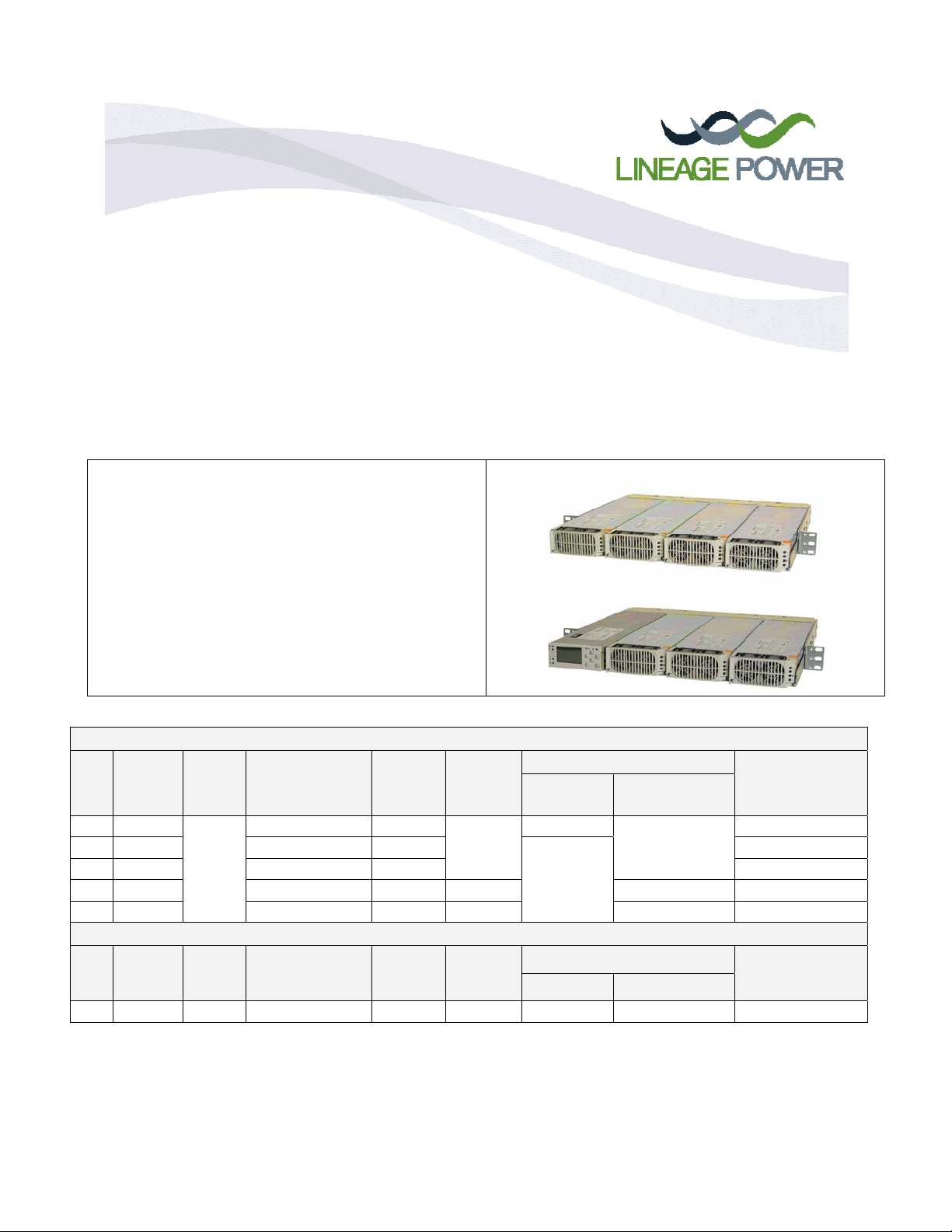
Compact Power Line Shelves
Model: J85480S1, L1 – L14
The 1U (1.75”) high CPL family of shelves mount in 19-inch wide frames and provide up to 11kW of 48V
output power per shelf. There are three or four slots for rectifiers, converters (PEMs). L1 accepts the CP843A
full featured Pulsar controller for applications requiring plant contro l.
Only 16.81” wide fits inside equipment that is designed
into a 19” rack
Two DC Outputs may be common or split. Each output
bus is rated for 100A with two-hole lug landings for 2 AWG
wire.
Either IEC-320 or AMP Mate_N_Lok AC inputs
Analog, RS485 or dual/redundant I2C communications.
Adjustable mounting ears for flush or set back positions.
Stackable up to 8 high with 32 paralleled power supplies.
Optional CP843A controller w/display & interactive panel
Rectifier Shelves (AC Input, DC Output)
DC
Max
Power
List
1 8kW
4 8kW IEC-320, C13 Common
6 8kW AMP Mate_N_Lok Common CC109104378
7 11kW AMP Mate_N_Lok Split CP2725 Analog. I2C CC109121902
9 8kW IEC-320, C13 Split CP2000 Analog. I2C CC109137072
PEM Shelves (DC Input, DC Output)
List
Capacity
14 8kW 2 AMP Power-Blade Split CP2000 No Analog, I2C CC109124764
Notes:
List 1 shelf allows side access to CP843A Pulsar Controller Outputs.
L7, L9: Split Bus Shelves cannot be paralleled. L1, L4, L6: Up to eight shelves may be paralleled.
# AC
Inputs
4
# DC
Inputs
Output
AC Input Plug
IEC-320, C13 Common
DC Input Plug
Bus
DC
Output
Bus
Max
Rectifier
Size
CP2000
Max
PEM
Size
Consult the factory for product availability
Communications Features
Shelf
Controller
CP843A Analog, I2C RS485 CC109143723
No
Communications Features
Controller Protocol
Protocol
Ordering
Codes
108994538
Ordering
Codes
Page 2
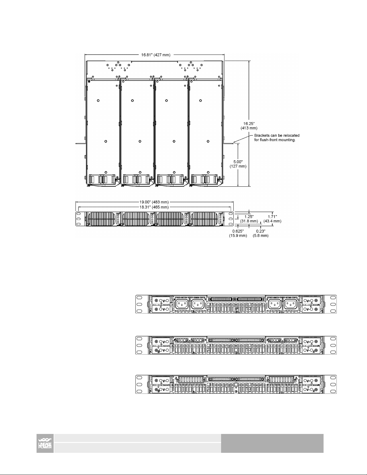
Rear Views
Lists 1, 4, 9
Lists 6, 7
Lists 14
Package Outline
DC AC J2 J1 AC DC
DC AC J2(L6 only) J1 AC DC
DC DC-IN J1 DC-IN DC
COMPACT POWER LINE SHELVES – MODEL J85480S1
2 of 10
Page 3

AC Input Connections
Tie_rap secured AC cables for IEC-320 inputs AMP Mate-N-Lok input connections
AMP Mate_N_Lok connector piece parts
Plug Front
P/N 770033-1
Plug rear
P/N 770034-1
AMP Mate-N-Lok input connector housing P/N 770018-1 Pin located in housing
DC Input Connection – L14 shelf
Lineage orderable part #: CC848794908
Includes 4 feet of un-terminated #10ga stranded wires on
one end and the AMP multi-beam connector on the other
end.
Pins Color Signal Unit
1 – 2 Black -48V
3 – 4 Red RTN
5 – 6 Black -48V
7 – 8 Red RTN
1
2
Gauge Part #
10 AMP 193796-1
12 – 14 AMP 193841-1
Housing: AMP 1600798-6 multi-beam XL
Contacts: AMP 1-1600960-8
Wire: 10 ga stranded – 30A rated capacity
COMPACT POWER LINE SHELVES – MODEL J85480S1
3 of 10
Page 4

DC Output Connections
Each Output Bus is rated for
100A and up to 2 gage twohole lugs.
M6 nuts with conical washers
provided.
Touch-Safe plastic covers
around output buses.
T o rqu e to 50 in-lb
(5.7 nm)
Torque to 50 in-lb
(5.7 nm)
DC Split Output Bus Option
Split Vout ( - ) buses on either
side of the shelf. Vout ( + ) is
common to both sections.
2
+5V bias maintains I
C
communications even during
a feeder fault.
Multiple shelves may not be
paralleled together.
Controllerless Operation
Lists 4 and 6 ship with a jumper
installed on connector J1 pins 21 and
23. This allows the shelf to be powered
without a controller. Remove this
jumper if controller cable installed.
CP843A controller ships with a
connector that plugs into J1 on a List 1
shelf activating the controller.
Lists 7, 9 and 14 require cc848836107
connector be installed in J1 to allow the
shelf to power up without a controller.
Rectifier
or
PEM
Bus A
Output
Feeder-A Feeder-B
Bus B
Output
Two DC Output
Busses
AC or DC Input
Feeds
L7, L9, L14 P1 Mating connector (pin out is standard 40 position like L4)
Type Housing Mating pin Crimping tool
Individual wire set AMP 102387-9 RoHS
40 position Ribbon cable AMP 1658621-9 e/w 499252-1 (strain relief) RoHS
20-24 awg: 6-87523-9
22-26 awg: 6-87756-8 91517-1
This connector set is different because it can accept either a ribbon cable or an individual wire mate.
COMPACT POWER LINE SHELVES – MODEL J85480S1
91517-1
4 of 10
Page 5

Communication Signals: J1 Connector
Pin out Control Interface Connection (J1 - AMP 499913-9)
Pin Signal Pin Signal
1 POWER_CAP_4 21 Enable side A
2 POWER_CAP_3 22 5VA
3 POWER_CAP_2 23 Logic_GRD
4 POWER_CAP_1 24 Interrupt_1
5 MOD_PRES_4 25 Reset
6 MOD_PRES_3 26 Enable Side B
7 MOD_PRES_2 27 Spacing
8 MOD_PRES_1 28 Spacing
9 PFW_4 29 RS_485_Select
10 PFW_3 30 Shelf_Addr_A
11 PFW_2 31 Shelf_Addr_B
12 PFW_1 32 Shelf_Addr_C
13 SCL_0 33 Shelf_Addr_D
14 SCL_1 34 Shelf_Addr_E
15 SDA_0 35 Shelf_Addr_F
16 SDA_1 36 Shelf_Addr_G
17 OTW 37 Protocol_S
18 Margin 38 RS-485+
19 Fault 39 RS_48520 Interrupt_0 40 Ishare
Communication Signals: J2 Connector ( cannot be used in split shelves L7, L9, L14)
Pin out Multi-shelf Connection (J2 – AMP 499913-8)
Pin Signal Pin Signal
1 PFW_4 18 Enable Side B
2 PFW_3 19 Spacing
3 PFW_2 20 Spacing
4 PFW_1 21 RS_485_Select
5 SCL_0 22 Shelf_Addr_B
6 SCL_1 23 Shelf_Addr_C
7 SDA_0 24 Shelf_Addr_D
8 SDA_1 25 Shelf_Addr_E
9 OTW 26 Shelf_Addr_F
10 Margin 27 Shelf_Addr_G
11 Fault 28 Shelf_Addr_H
12 Interrupt_0 29 Protocol_S
13 Enable side A 30 RS-485+
14 5VA 31 RS_48515 Logic_GRD 32 Ishare
16 Interrupt_1 33 Spare
17 Reset 34 Spare
Note: Shelf addressing, current share and RS485 communications are all referenced to the most negative
power output Vout(-) of the shelf. For paralleled shelves the Vout(-) terminations must be tied together in order
to ensure proper operation of these functions. Modules could get damaged if this connection is not made. .
COMPACT POWER LINE SHELVES – MODEL J85480S1
5 of 10
Page 6

CP843A installs in slot 1 of a J85480S1 List 1 shelf.
Connections to the controller are made on the left side as
shown.
CP843A controller comes with wire set that plugs into J1
connector to enable the controller.
Specifications
Parameter Min Max Notes
Input
AC Input Current, per module 15A
30A
DC Input Current, per module 60A
Output
Programmable output set point 42Vdc 58Vdc Minimum 44Vdc via hardware marginning
Max Output Current J85480S1 200A lugs for 2 ga wires, 2 pairs, 100Amax
Output Terminations M6 threaded studs on 5/8-inch centers.
Environmental
Operating Temperature Range -40°C to 55°C, except J85480 L6, L7, L14 may be used up to 75°C
Operating Relative Humidity 0 - 95% (non-condensing)
Storage Temperature Range -40°C to 85°C
EMC FCC, EN 55022, CISPR22, Level A, conducted and radiated
Immunity FCC and CISPR22 (EN55022) Class A2
Safety/Standards Compliance
Safety Standards UL1950, EN60950 (IEC950), CSA*234/950
Certification Marks Lists 6,7,14: VDE,
UL Recognized (Canada and U.S.)
Lists 1,4,6,9: VDE,
UL Listed (Canada and U.S.)
IEC-320, C13 type
AMP Mate-N-Lok connectors
COMPACT POWER LINE SHELVES – MODEL J85480S1
6 of 10
Page 7

Ordering Information
Part Number Description Comcode Usage
Blank Slot Fillers
Central Office White CC848822263 All
Raven Black CC848781534
Graphite CC848825233
Extensions and mounting brackets
CP 19 inch mounting bracket kit (includes two brackets and mounting hardware) CC109145760 L8
1U high extension bracket kit for 23” cabinets (includes two brackets and mounting hardware) CC848844803 All
2U high extension bracket kit for 23” cabinets (includes two brackets and mounting hardware) 848683009 All
Cables / Connectors for J85480S1 Shelves
Ribbon cable for attaching a controller to the power shelf – 10 ft. One end mates into J1
the other end not terminated.
Inter-shelf connector for daisy-chaining shelves – 9 in between J1 of 2nd and J2 of 1st shelf 848738253 L1, L4, L6
2 AWG DC output cable set – 10 ft ( 1 RED and 1 BLACK cable) 848748987 All
AC Input cable: High temperature IEC 320 C13 straight over-mold (one end), NEMA5-15P
plug (one end), 14 AWG, 10 ft
AC input cable: IEC 320 C13 plug (one end), other end not terminated , 14 AWG, 14 ft, 847861192 L1, L4, L9
AC input cable: AMP 3-pin Mate-N-Lok, 14 AWG, 3 ft, other end not terminated CC848763301 L6, L7, L8, L9
AC input cable: AMP 3-pin Mate-N-Lok, 14 AWG, 10 ft, other end not terminated CC848793026 L6, L7, L8, L9
Inter-shelf cable for RS-485 specific shelf. CC848786153 L8
Office alarm cable for RS-485 specific shelf CC848786161 L8
DC input cable – 4 ft CC848794908 L14
Shorting jumper for J1 connector ENABLE for single output shelf (see locating picture) AMP 881545-2 L4, L6,
P1 connector ENABLE jumper for split shelf CC848836107 L7, L9, L14
Pulsar Controllers for J85480S1 Shelves Picture
NE843G 1U standalone Controller (Display, DB9 craft port and RJ45 ethernet) CC109139358
848738245 L1, L4, L6
CC848776105 L4, L5
CP843A CP Shelf Mounted Controller (Display and RJ45 ethernet) CC109129895
Cables for Pulsar Controllers
NE843G to CP Shelf Cable Kit (Includes 2ft power and communication cable) CC109144820
J4 Output Alarm Cable 50ft – 24ga solid twisted pair CC848817635
J4 Output Alarm Cable 150ft – 24ga solid twisted pair CC848817643
J3 Input Alarm Cable 50ft – 24ga Stranded CC848817651
J3 Input Alarm Cable 150ft – 24ga Stranded CC848817668
COMPACT POWER LINE SHELVES – MODEL J85480S1
7 of 10
Page 8

Safety
Safety Symbols and Guidelines
Read and understand all instructions before attempting any installation of this product. When installing, operating,
or maintaining the J85480S1 Power System, basic safety precautions should always be follo wed to reduce the risk
of fire, electric shock, and injury to persons. Such precautions include the following:
This symbol identifies the need to refer to the equipment instructions for important
information.
This symbol identifies the presence of hazardous AC or DC voltages or hazardous
energy levels. In the context of this product
The DC output cables contain electrical energy levels capable of causing
heating and arcing if shorted to metal objects. Make connections with the power
disconnected.
Hazardous AC voltage and DC electrical energy is contained within the
enclosure of the power shelf. No user or field serviceable parts inside.
This symbol is used to identify safety earth ground connection points within the
equipment.
Product Labeling
Follow all warnings and instructions marked on the product. Some of the safety symbols used with the CP1800
Rectifier and J85480S1 Shelf may include the following. They may also be accompanied by instructions:
Mounting and Installation
• This product shall be installed in compliance with mounting requirements for the ultimate application.
• This product must be installed, serviced, and operated only by skilled and qualified personnel who have the necessary
knowledge and practical experience with electrical equipment and who understand the hazards that can arise when working on
this type of equipment. This product is intended for use in a Restricted Access Location.
• This equipment is to be used in controlled environments (an area where the humidity is maintained at levels that cannot cause
condensation on the equipment, the contaminating dust is controlled, and the steady-state ambient temperature is within the range
specified).
• This equipment has been evaluated for use in a continuous ambient temperature of up to 55°C and the application environment
should not exceed 55°C.
• The CE mark if provided on the product is applied to show conformance to the requirements outlined in the European Union’s
Low Voltage Directive {72/73/EEC} and EMC Directive {89/336/EEC}, as amended by the CE Mark Directive {93/ 68/EEC}.
• The J85480S1 shelf, when used with the CP1800 rectifiers, has been evaluated for hot swapping.
• A separate protective Earthing terminal is provided at the reach of the shelf
– the building installation shall provide a means for connection to protective earth; and
– the equipment is to be connected to that means; and
– a SERVICE PERSON shall check whether or not the socket-outlet from which the equipment is to be powered provides a
connection to the building protective earth. If not, the SERVICE PERSON shall arrange for the installation of a PROTECTIVE
EARTHING CONDUCTOR from the separate protective Earthing terminal to the protective earth wire in the building.
COMPACT POWER LINE SHELVES – MODEL J85480S1
8 of 10
Page 9

Output Connections
• All field wiring should comply with the U.S. National Electrical Code (NEC) and/or applicable local codes/standards.
• Routing of the DC output cables should guarantee that cables are not in contact with sources of heat and surfaces that may
damage the cable insulation.
• The DC output is not provided with a fuse or circuit breaker suitable for branch circuit protection. Therefore, the power shelf
should be mounted in the same rack or cabinet as the equipment being powered. Use interconnecting power cables suitable for
the application and sized to carry the rated output current. The interconnecting cables should be capable of carrying the overload
current and short circuit current without damage or risk of fire.
• The output for the system is SELV and has available power greater than 240VA.
• Insulation on output field-wired conductors should be rated no less than 90°C. Wiring internal to enclosed equipment cabinets
should be rated at 105°C (minimum). The provided DC output cords (red and black wires) are rated for 105°C.
• Before opening the insulating cover to gain access to load and ground connections, ensure all power supplies are disconn ected
from the AC MAINS.
AC Input Connections
• AC branch circuits to this equipment must be protected with fuses or circuit breakers sized as required by the U.S. National
Electric Code (NEC) and/or local codes. Up to four AC mains power cords are required to power the shelf (one for each rectifier).
Each power cord should be connected to a separate AC mains branch circuit with an overcurrent protector rated at no more than
20A.
• The power supply mains inlet may be used as the means to provide AC protective earthing.
• An accessible AC disconnect/protection device to remove AC power from the equipment in the event of an emergency must be
provided. An accessible socket-outlet/receptacle installed near the equipment is also acceptable as a disconnect.
• The equipment is powered by multiple AC inputs (one per rectifier). Disconnect all AC sources of power before servicing.
• These units are to be used with TN-S power systems only.
German Safety Guidelines
Installationsanleitung
• Alle Ausgänge des Gerätes erfüllen die Anforderungen für SELV nach IEC/EN60950-1.
• Die Ausgänge des Gerätes liegen über den Limits für Energiegefahr nach IEC/EN60950-1 (>240 VA). Das Gerät ist zum
Einbau in ein Montage-Rack bestimmt. Siehe Einbaubestimmungen in der Montageanleitung, um eine Gefährd ung des
Benutzers während der Installation zu vermeiden.
ACHTUNG:
Hoher Ableitstrom Vor Anschluss an den Versorgungsstromkreis unbedingt Erdungsverbindung herstellen
• Das Produkt ist zum Gebrauch in einer Umgebungstemperatur von max. 55°C bestimmt.
• Die Gerätestecker des Produktes sind dazu bestimmt, eine sichere Erdung des Gerätes herzustellen.
• Das Produkt ist zum Gebrauch in einer Umgebung mit Verschmutzungsgrad 2 nach IEC/EN60950 bestimmt.
• Die Netzteile des Gerätes können während des Betriebes einzeln ausgetauscht werden (Hot Swapping).
• Das Gerät wurde zusammen mit den Anschlussleitungen (ohne Anschlussstecker) geprüft. Die Installation eines Steckers des
jeweiligen Landes, sollte nur durch geschultes Service Personal durchgeführt werden.Als alternative könnte eine Vorinstall ation
des Steckers bereits bei der Herstellung erfolgt sein.
COMPACT POWER LINE SHELVES – MODEL J85480S1
9 of 10
Page 10

Europe, Middle-East and Africa Headquarters
Lineage Power (UK)
Tel: +44 (0) 1344 469 300, Fax: +44 (0) 1344 469 301
Caribbean-Latin America-Brazil Headquarters
World Wide Headquarters
Lineage Power
3000 Skyline Drive, Mesquite, TX 75149, USA
+1-800-843-1797
power.lineagepower.com
Lineage Power
Tel: +56 2 209 8211, Fax: +56 2 223 1477
Asia-Pacific Headquarters
Lineage Power Singapore
Tel: +65 6416 4283, Fax: +66 6416 4299
India
Lineage Power India
Tel: +91 80 841 1633 x3001
Lineage Power reserves the right to make changes to the product(s) or information contained herein without notice. No liability is assumed as a
result of their use or application. No rights under any patent accompany the sale of any such product(s) or information.
©2010 Lineage Power (Mesquite, Texas) All International Rights Reserved.
GGS – March 2010
COMPACT POWER LINE SHELVES – MODEL J85480S1
10 of 10
 Loading...