

Page 1

User Manual for the
HE300GEN250,
HE300GEN251
Genius
Serial Bus
Interface Option Card for
GE AV-300i
Adjustable Speed Drive
First Edit ion
23 September 1999
MAN0308-01
Page 2

PREFACE 23 SEP 1999 PAGE 3
PREFACE
This manual explains how to use the Horner AP G’s Genius Serial Bus Interfac e Opti on Car d for GE
Drives AV-300i Adjustabl e S peed Dr ives.
Copyright (C) 1999 Horner A PG, LLC., 640 North Sherman Drive I ndianapolis, Indiana 46201. All right s
reserved. No part of this publi cation may be reproduced, transmitted, transcri bed, stored in a retrieval
system, or translated into any language or computer language, in any form by any means, el ectronic,
mechanical, magnetic, optical, chemical, manual or otherwise, without the prior agreement and written
permission of Horner A PG, LLC.
All software described i n this document or media is also copyrighted materi al subject to the terms and
conditions of the Hor ner S oft ware Li c ense Agreement.
Information in this document is subject to change without notic e and does not represent a com mitm ent on
the part of Horner APG, LLC.
Series 90-30 and VersaPro are t r ademarks of GE Fanuc Automation.
AV-300i Drive is a trademark of GE Motors & Industrial Systems.
IGE Control System Toolbox is a trademark of GE Motors & Industrial Sy stem s.
For user manual updates, contact Horner APG, Technical Support
Division, at (317) 916- 42 74 or visi t our web sit e at www. h ea pg.c om .
Page 3

PAGE 4 23 SEP 1999 PREFACE
LIMITED WARRANTY AND LIMITATION OF LIABILITY
Horner APG, LLC. ("HE-APG") warrants to the original purchaser that the Genius Serial Bus Interface
Option Card for GE Drives AV-300i Adjustable Speed Drives manufactured by HE-APG is free f rom
defects in material and workmanship under normal use and servic e. The obligation of HE-APG under this
warranty shall be limited to the repair or exchange of any part or parts which may prove def ective under
normal use and servi ce within two (2) years from the date of manufacture or eighteen (18) mont hs from
the date of install ation by the origi nal purc haser whichev er occur s first, such def ect t o be di scl osed to t he
satisfaction of HE-APG after examination by HE-APG of the allegedly defective part or parts. THIS
WARRANTY IS EXPRESSLY IN LIEU OF ALL OTHER WARRANTIES EXPRESSED OR IMPLIED
INCLUDING THE WARRANTIES OF MERCHANTABILITY AND FITNESS FOR USE AND OF ALL
OTHER OBLIGATIONS OR LIABILITIES AND HE-APG NEITHER ASSUMES, NOR AUTHORIZES ANY
OTHER PERSON TO ASSUME FOR HE, ANY OTHER LIABILITY IN CONNECTION WITH THE SALE
OF THIS Genius Serial Bus Interface Option Card for GE Drives AV-300i Adjustable Speed. THIS
WARRANTY SHA LL NOT APPLY TO T HIS Genius Serial B us Interface Option Card for G E Drives AV300i Adjustable Speed Drives OR ANY PART THEREOF WHICH HAS BEEN SUBJECT TO
ACCIDENT, NEGLIGENCE, ALTERATION, ABUSE, OR MISUSE. HE-APG MAKES NO W ARRANTY
WHATSOEVER IN RESPECT TO ACCESSORIES OR PARTS NOT SUPPLIED BY HE. THE TERM
"ORIGINAL PURCHASER", AS USED IN THIS WARRANTY, SHALL BE DEEMED TO MEAN THAT
PERSON FOR WHOM THE Genius Serial Bus Interface Option Card for GE Drives AV-300i
Adjustable Speed Drives IS ORIGINALLY INSTALLED. THIS WARRANTY SHALL APPLY ONLY
WITHIN THE BOUNDARIES OF THE CONTINENTAL UNITED STATES.
In no event, whether as a result of br eac h of contract, warranty, tort (including negligence) or ot her wise,
shall HE-APG or its suppliers be liable of any special, consequenti al, incidental or penal damages
including, but not limi ted to, loss of profit or revenues, loss of use of the produc ts or any associated
equipment, dam age to associat ed equipment, cost of capit al, cost of substitute product s, facilities,
services or replacem ent power, down time costs, or claims of original purchaser's customers for such
damages.
To obtain warranty service, return the product to your distributor with a description of the
problem, proof of purchase, post paid, insured and in a suitable package.
ABOUT PROGRAMMING EXAMPLES
Any example programs and program segments in this manual or provided on accompanying diskettes are
included solely for illustrative purposes. Due to the m any variables and requirements associated wit h any
particular installation, Horner APG cannot assume r espon si bility or liability for actual use based on the
examples and diagrams. It is the sol e r esponsibility of the system designer utilizing Genius Serial Bus
Interface Option Card for GE Drives AV-300i Adjustable Speed to appropri ately design the end system,
to appropriat ely integrate the Genius Serial Bus Interf ac e Opti on Car d for GE Drives AV-300i
Adjustable Speed Drives and to make safety provisions for the end equipment as is usual and customary
in industrial applications as defined in any codes or standard s whi c h apply.
Note: The programming examples shown in this manual are for illustrative
purposes only. Proper machine operation is the sole responsibility of the
system integrator.
Page 4

PREFACE 23 SEP 1999 PAGE 5
TABLE OF CONTENTS
PREFACE............................................................................................................................................... 3
LIMITED WARRANTY AND LIMITATION OF LIABILITY......................................................................... 4
ABOUT PROGRAMMING EXAMPLES ................................................................................................... 4
CHAPTER 1: INTRODUCTION..............................................................................................................7
1.1 Product Description ................................................................................................................... 7
1.2 Functional Overview.................................................................................................................. 7
1.3 Before Getting Started - Order of Configuration and Set up ........................................................ 8
1.4 Required References and Resourc es........................................................................................ 9
CHAPTER 2: DRIVE OVERVIEW .........................................................................................................11
2.1 General....................................................................................................................................11
2.2 Two Versions of SBI Cards Available / Using an Additional Option (DGF Car d) ........................11
2.3 High and Low Priority Communication Channels ......................................................................11
2.4 DGF P a rameters......................................................................................................................12
CHAPTER 3: GEN250/251 COMMUNI CATIO NS (SBI CA RD) ..............................................................13
3.1 GEN250/251 Operation............................................................................................................13
3.2 Automatic Data Transfer ..........................................................................................................13
3.3 GEN250/251 to/fr om GBC Communication using Global Data..................................................13
3.4 SBI (GEN250/251) Configuration Procedures using GE Toolbox Software................................14
3.4.1 Initial Steps Before Starting Configuration .........................................................................14
3.4.2 SBI (GEN250/251) Configuration Procedures....................................................................15
CHAPTER 4: GENIUS COMMUNICATIONS.........................................................................................29
4.1 Introduction to G enius .............................................................................................................29
4.2 Network Architecture................................................................................................................29
4.3 Genius Communications Services............................................................................................30
4.4 I/O Service...............................................................................................................................30
4.5 Global Data..............................................................................................................................30
CHAPTER 5: PLC CONFIGURATION...................................................................................................31
5.1 General....................................................................................................................................31
5.2 Series 90-70 Confi gur ation.......................................................................................................31
5.3 Series 90-30 Confi gur ation.......................................................................................................33
a. Device Typ e.............................................................................................................................34
b. Input References (Input 1 Ref, Input 2 Ref) ..............................................................................34
c. Input Length (Input 1 Len, I nput 2 Len).......................................................................................34
d. Output References (Output 1 Ref, Output 2 Ref) ......................................................................35
e. Output Length (Output 1 Len, Output 2 Len).............................................................................35
CHAPTER 6: AV-300i DRIVE PARAM ETE RS........................................................................................37
6.1 Drive Parameter Descriptions...................................................................................................37
CHAPTER 7: WIRING DIAGRAMS.......................................................................................................39
7.1 Gen iu s Wiring:.........................................................................................................................39
7.2 RS232/RS485 Pinout:..............................................................................................................40
Page 5

PAGE 6 23 SEP 1999 PREFACE
CHAPTER 8: INSTALLATION OF GEN250/251 OPTION CARD...........................................................41
8.1 General....................................................................................................................................41
8.2 GEN 250 Installation................................................................................................................41
8.2.1 Installation Hardware.........................................................................................................41
8.2.2 Installation Procedures......................................................................................................41
8.2.3 Cover Removal.................................................................................................................41
8.2.4 Housing Remov al..............................................................................................................42
8.2.5 Regulation Car d Rem ov al .................................................................................................43
8.2.6 Mounting the GEN250 Car d ..............................................................................................43
8.2.7 Re-assembly.....................................................................................................................45
8.3 GEN 251 Installation................................................................................................................48
8.3.1 Installation Hardware.........................................................................................................48
8.3.2 Installation Procedures......................................................................................................48
CHAPTER 9: GEN250/251CARD LED INDI CATORS............................................................................51
Page 6

CH. 1: INTRODUCTION 23 SEP 1999 PAGE 7
CHAPTER 1: INTRODUCTION
1.1 Product Descrip tion
The Genius Serial Bus Interface Option Card for GE AV-300i Adjustabl e Speed Drive
(HE300GEN250/251) is a Genius Serial Bus Interf ac e (SBI) that resides
(GEN250) or is located
externally
to the drive (GEN251). The GEN250/251 allow communication over a
Genius Network by providing a communication port between an AV-300i drive and a master device (such
as a Genius Bus Controll er ), whic h is l oc ated in a PLC.
1.2 Functional Overview
Figure 1.1 depicts a func tional overview of the major devices used wit h the GEN250/251 in a Genius
Network.
1. To allow communications between t he Genius Bus Controller (GBC) in the PLC and the AV-300i drive,
specific parameters must be the same for the GEN250/251 as the GBC. Parameter information is
configured and loaded into the GEN250/251 via a PC. This is accomplished using the GE Control
System Toolbox Softw are Con figu rat io n Tool .
internally
within the drive
6. SBI
(GEN251) -
Provides a
comm port
between the
drive and
Genius
Network.
external
Is
the drive. Must
be used when
the DGF Card
is installed.
to
1
. A PC is use d to
download
the conf iguration into
each AV-300i drive on
the Genius Network.
The c onfigur ation is
downloaded into the
drives via the
connector on the
GEN250/251.
SBI
1
GEN25
AV-300i Drive
DGF Card
-
2. A Series 90-30 PLC
Series 90-70 PLC
or
is used.
SBI
0
GEN25
AV-300i Drive
5. SBI
(GEN250) -
Provides a
comm port
between the
drive and
Genius
Network.
internal
Is
the drive.
3. Genius Bus
Controller
as the
Genius Network.
4. Genius Network
Has up to 32 devices.
to
functions
Master
for the
7. DGF Card
Option
provides extra
functionality.
-
Figure 1.1 – Overview of GEN250/ 251 in a Genius Network
Page 7

PAGE 8 23 SEP 1999 CH.1: INTRODUCTION
2. – 4. A PLC is the main controlling elem ent of the G enius Network and contains the Genius Bus
Controller (GBC) module, which functions as the master for the Genius Network. Communications over
the Genius Network are coordi nated via the master device. The GBC serves as an int erface between the
PLC and the Genius Network. The Genius Network contains up to 32 devices.
5. – 6. The GEN250/251 allow communications over a Genius Network by providing a communication
port between an AV-300i drive and a master device such as a Genius Bus Controller (GBC), which is
located in a PLC.
The GEN250/251 serve as Serial Bus Interfaces (SBI) and are GENA based. Thus, the GEN250/251 are
slave only Genius comm unic ations devices and can not control other dev ices on the Genius bus. They
also can not look at other devic e data. Communication is accomplished using t he standar d Genius
format by sending Broad cast (Glo bal) Data to the GBC and listening to Directed Contro l Data
GBC. The GEN250/251all ow up to 32 words of B r oadc ast Data and up to 16 words of Directed Data to
be configured per drive.
The GEN250 and the GEN251 have identical functions but differ physically. The GEN250 is placed
internally
reason for the external m ounting capability is that some applications require the instal lation of an
additional option card (DGF Option Card) in the AV-300i drive where a GEN250 is typic ally insert ed.
Thus, the GEN251 can be used as an interface in such cases, because it is external to the AV-300i. (The
DGF Option Card is discussed in Ch apter Two.)
within the AV-300i drive. The GEN251 is
externally
mounted outside of the AV-300i drive. The
from
the
1.3 Before Getting Started - Order of Configuration and Setup
This manual covers several procedures involving various devices that must be configur ed and setup.
Although not requi r ed, the following order is suggested to setup and configure the GEN250/251 and other
related Genius devices in an orderly and efficient manner.
1. Analyze the specifi c ations and requirements of the applic ation.
Note: Refer to Section 1.2 for a functional overview of a Genius Network containing the
GEN250/251 modul es i n this user manual (Horne r Ge nius Serial Bus Interface Option Card
for GE AV-300i Adjustable Speed Drive user manual [MAN0308]). It is also recommended
to read Chapter 4 which cover s el em ents applicable to Genius Communicati ons.
2. Become familiar with the parameters listed in the GE Indust rial Con t rol Systems AV-300i
before
Adjusta ble S pe e d Dr ives Instruction Manual
a. Determine whic h par am eters must be used to meet the requirements and specif ic ations of the
applicati on.
Required parameters must be determined before starting conf igur ation procedures for the
starting any configuration procedures.
SBI (GEN250/251).
Note: There is a chapter in GE’s manual that provides Parameter Lists and includes tables that
list the paramet er s i n
informati on about t he par am eters, which is needed for configurat ion.
alphabetical order
and
numeric order
. Each table provides different
Page 8

CH. 1: INTRODUCTION 23 SEP 1999 PAGE 9
b. Determine which of t he r equir ed par am eters need to be high priority or low priority when
communicati ng with AV-300i Drive. High priority parameters can be accessed much more quickly than
low priority par am eters. There is a limit of six high priority paramet er s. (See Ch apter 2 for information
covering high and l ow pri ori ty parameters in this user manual (Horner Genius Serial Bus Interface
Option Card for GE AV-300i Adjustable Speed Drive [MAN0308]. Also recommended is Chapter 6,
which provides addit ional information about drive parameters.)
3. Install the SBI Car d (GE N250/251) into the AV-300i Drive. (See Chapter 8 for procedures.)
4. Wire the Genius Network and t he S BI Car d (GE N250/251). (See Chapter 7 for wiring
diagrams.)
5. Configure t he SBI (GEN250/ 251) usi ng GE Control System Toolbox Soft ware. Upon c om pleting
the configuration, information is provi ded that is usef ul to know for configuring the Geni us Bus Controller
(GBC) and for writing the Ladder pr ogr am . (See Chapter 3 for GEN250/251 configurat ion
procedures.)
Note: It is highly recommended that the user refer to t he GE Control Toolbox Help File at this time
to obtain highly useful information regardi ng the G enius Network Conf iguration. Select Help, click on
Contents, click Index tab, and type Genius Configuration.
6. Configure t he Genius Bus Controller (GBC) using Logicm aster 90. Using summary screen
information from the GEN250/251 configuration, determine the Global Data length and the Directed
Control Data lengt h as well as baud rat e and network id information. (See Chapter 5.)
7. Write the Ladder program and r efer to the summary information in the GE N250/251 configuration.
1.4 Required References and Resou rces
This manual is to be used in conj unction with the in GE Industrial Control Systems AV-300i Adjustable
Speed Drives Inst ructio n Manu al, the GE Control System Toolbox software con f ig uration help file,
and the GE Fanuc Genius I/O System and Communications User Manual.
NOTE: It is highly recommended t hat t he user refer to the GE Control Toolbox Help File at this tim e to
obtain highly useful information regardi ng the Geni us Network Conf iguration. Select Help, click on
Contents, click Index tab, and type Genius Configuration.
Page 9

PAGE 10 23 SEP 1999 CH.1: INTRODUCTION
NOTES
Page 10

CH. 2: DRIVE OVERVIEW 23 SEP 1999 PAGE 11
CHAPTER 2: DRIVE OVERVIEW
2.1 General
It is important to have a basic understanding of how the AV-300i Drive interacts with the Genius Serial
Bus Interface (SBI ) such as the GEN250/ 251.
2.2 Two Versions of SBI Cards Availab le / Using an Additional Option (DGF Card)
There are two versions of the SBI c ar d - the
GEN251.
Note that there instances when the user needs to use both an SBI card as well as a separate opti on
called a DGF card. Only one option c ar d (either the GEN250 internal SBI card or the DGF card) can be
installed within the drive. If the applic ation requires
must be mounted
the drive. If the applicati on does not r equire a DGF card, either the GEN250 SBI card or the GEN251
SBI card can be used.
The SBI provides a communi c ations path between itself and the drive. The SBI can ac c ess any
predefined parameter within t he AV-300i drive. Reference the AV-300i instruction manual f or a
description of each of the available drive paramet er s.
2.3 High and Low Priority Communication Channels
The SBI provides two communic ations channels to and from the drive, high priority and low priority. A
maximum of 16 directed control word parameters and 32 global data word parameters are allowed. Of
these, up to 6 can be assigned to the high pri or ity channel. The balance must be assigned to the to the
low priority channel . All parameters assigned to the high prior ity channel are exchanged with the drive
every 2 milliseconds. The drive can also pack/unpack up to 16 high priority bit parameters into/fr om a
single high priori ty word parameter. If this feature is used, 5 high priority word parameter s and 16 hi gh
priority bit param eters can be processed. Due to the relatively small number of parameters available in
the high priorit y channel, these parameters should be reserved for the most critical parameters.
To access each low priori ty par am eter, the SBI must poll the drive one paramet er at a time. Thi s process
is very time consuming. A minimum of 100 milli seconds is required to access each drive parameter. The
SBI can also pack/unpack up to 16 low prior ity bit parameters into/f r om a single low priority word
parameter.
internal
to the drive. In this case, the GEN251 SBI c ar d must be mount ed
internally
mounted GEN250 and the
both
an SBI card and a DGF card, the DGF card
externally
mounted
external
to
Page 11

PAGE 12 23 SEP 1999 CH.2: DRIVE OVERVIEW
2.4 DGF Parameters
The DGF provides an additional group of low priority parameters independent of the drive's parameters.
The only way to directly ac c ess the DGF param eters is via the low priority communic ations channel.
Page 12

CH. 3: GEN250/251 COMM. 23 SEP 1999 PAGE 13
CHAPTER 3: GEN250/251 COMMUNICATIONS (SBI CARD)
3.1 GEN250/251 Operati on
Automatic Data Transfer is a type of Genius communication that c an be used between the G enius Bus
Controll er (GBC) and the SBI.
The automatic data t r ansfer type of communication uses broadcast (global) data to transfer inf ormation
from the GEN250/251to the GBC, and directed control data to transfer information from the GBC to the
SBI. With this data type, the GBC is always communicating with the SBI.
3.2 Automatic Data Transfer
To communicate with G enius using Automatic Data Transfer, all of t he requi r ed par am eter information
previously discussed in the Drive Overview section (the global data to transfer information from the SBI,
and Directed Cont r ol Data t o transfer data from the GBC to the SBI) must be configured and l oaded into
the SBI.
The GEN250/251 configuration is accomplished using the GE ToolBox software configur ation tool. The
configurati on por tion consists of the Genius bus configur ation parameters and two memory maps, t he
global data memory map, and the directed control data memory map. The memory maps associat e
parameter names (or parameter numbers) and other paramet er information with corresponding G enius
data words. The GE ToolBox confi gur ation tool uses “pick lists” for choosing par ameters. The pick lists
change depending on which ac c ess method is chosen. This eliminates the need to manually determine
all of the information described in the Drive Overvi ew secti on.
The global data mem ory map contains a parameter name (or parameter number) and other parameter
informati on for eac h global data word from the drive to the GBC. The directed cont r ol data memory map
contains a param eter nam e ( or parameter number) and other parameter information for each directed
control word from the GBC to t he drive. Once the memory maps are created using GE ToolBox, they are
downloaded into the GEN250/251 non-volatil e memory .
The software configur ation tool is setup in such a manner so that when the user choose s a parameter
from the “pickli st” , t hat param eter is set at that global data word or directed data word. When the
GEN250/251scans a configuration, it separates the hi gh pr iority words and the low priority words and
stores them in two differ ent arrays.
3.3 GEN250/251 to/from GBC Communication using Global Data
After the configur ation is downloaded from the configuration tool to the SBI, the GEN250/251 t hen
configures the drive. The drive must be made aware of all of the high priority parameters (both Word and
Bit) that need to be passed between itself and the GEN250/251.
High priority par am eters are passed automatically between the drive and the GEN250/251 every 2
milliseconds.
Page 13

PAGE 14 23 SEP 1999 CH.3: GEN250/251 COMM.
Low priority par am eters are polled by the GEN250/251 as fast as the low pri ori ty c ommunications channel
allows. Each dir ected data parameter is individually polled, and then each global data par am eter is
individually polled; this sequence is repeated i ndefinitely. The greater the number of low priority
parameters that are c onfigured, the longer this polli ng pr oc ess takes. T he time required for the
GEN250/251 to poll one low priority drive parameter is greater than 102 milliseconds.
WARNING: If using the Toolbox on-line diagrams, t he low pri or ity parameters between the SBI and
the drive may cease to functi on. This is of concern, because the drive m ay stop updating low priority
parameters when on-line diagrams are displayed. This incl udes the r epor ting of the Bus Loss
Alarm.
3.4 SBI (GEN250/251) Conf ig uration Procedures using GE Toolbox Softw are
3.4.1 Initial Steps Befor e S tarting Configuration
Note: It is important to consult Section 1.3 prior to configuration. Section 1.3 provides a
suggested order for conf igurat ion and setup and contains a detailed li st of resource i nformation.
1. Prior to configuration, analyze the specifications and requirements of the applic ation. Become familiar
with the parameter s li sted in the GE Industrial Control Systems AV-300i Adjustable Speed Drives
before
Instruction Manual
starting any configuration procedures.
a. Determine which param eters must be used to meet the requirements and specif ic ations of the
applicati on.
Required parameters must be determined before starting conf igur ation procedures for the
SBI (GEN250/251).
b. Determine which of the required paramet er s need to be high priority or low priority when
communicati ng with AV-300i Drive. High priority parameters can be accessed much more quickly than
low priority par am eters. A maxim um of six hi gh pri ori ty Directed Control Data param eters and six high
priority Global Data parameters can be configured for each AV-300i.
3. Install the SBI Car d (GE N250/251) into the AV-300i Drive. (See Chapter 8 for procedures.)
4. Wire the Genius Network and t he S BI Car d (GE N250/251). (See Chapter 7 for wiring.)
5. When configuring the AV-300i/HE300GEN250, t her e is terminology that must be
understood. (See Chapter 6.)
Page 14

CH. 3: GEN250/251 COMM. 23 SEP 1999 PAGE 15
3.4.2 SBI (GEN250/251) Configuration Procedures
In this configuration example, the user followed the steps in Sectio n 3. 4.1 and has predetermined
which parameters and prio rities to choose for the two types of data in Genius – Directed Con t rol
Data and Global Data.
To configure for Direct ed Control Data, the parameter for Word0 is going to be “Discrete Bit Word,”
and the parameter f or Wo rd1 is going to be “Speed ref 1.” The user is going to select the words to
be high priority. The user must configure the bits as well. Bit0 is going to be “Enable Drive,” and
the parameter f or Bit 1 is goi ng to be “Star t/ S top.” To configure Global Data, the user employ s the
similar procedur es al though the desired parameter s and priorities can vary.
1. Install GE Control S yst em Toolbox Sof t ware by following the manufactur er ’s i nstr uc tions.After
openng the GE Toolbox Software, the following screen appears. S elec t File, New.
Figure 3.1
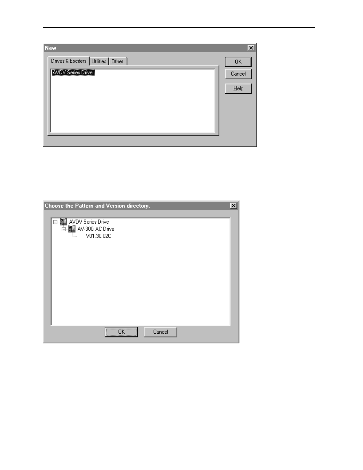
2. The following screen appear s. S elect AVDV Series Driv e and press OK.
Page 15
PAGE 16 23 SEP 1999 CH.3: GEN250/251 COMM.
Figure 3.2
3. The following screen appears. Select the AV-300I AC drive type and drive fi rmware version.
Note that there can be ot her drive information listed on thi s screen.
Figure 3.3
Page 16

CH. 3: GEN250/251 COMM. 23 SEP 1999 PAGE 17
4. Type in the User ID such as the user’s ini tials. Press OK.
Figure 3.4
5. Select the desir ed drive. In this configuration exam ple, the 6KAVI43F75 model is selected.
Press OK.
Figure 3.5
Page 17

PAGE 18 23 SEP 1999 CH.3: GEN250/251 COMM.
6. The following screen appear s. This step requires the user to name the configuration file for the
drive that is being configured. It also requires that the user selec t the Genius network.
In this example, the drive configuration name is AVDV1. If a diff er ent driv e nam e is desired ( such as
AVDV2), doubl e-click on the highlighted name (or right - cli c k on the nam e and sel ec t Modify).
Figure 3.6
7. The following screen appear s. Type in the drive name in the Name block, and from the Net work
block, select Genius from the pull-down menu. Press OK.
Figure 3.7
NOTE: It is highly recommended t hat t he user refer to the GE Control Toolbox Help File at this time to
obtain highly useful information regardi ng the Geni us Network Conf iguration. Select Help, click on
Contents, click Index tab, and type Genius Configuration.
Page 18

CH. 3: GEN250/251 COMM. 23 SEP 1999 PAGE 19
8. The following screen appear s. On the left side of the screen. a “tree” appear s. Note that the
Genius network is now listed as a part of the tree. The right side of the screen provides a status page
that correlat es to whatever item is highlighted on the “tree.”
Place the cursor on the Ex pand B ox locat ed in front of the word “Genius” on the left-side of the screen
and click the box to reveal t he items associated with Genius confi gur ation.
Figure 3.8
9. The following screen appears.
Figure 3.9
Page 19

PAGE 20 23 SEP 1999 CH.3: GEN250/251 COMM.
Figure 3.9 indic ates the types of data that must be configured in a Genius Network. The data types
include Directed Dat a and Global Data. To see the items that must be configured for each data type,
place the cursor in t he Expand box loc ated in front Directed Data and click. Then, do the same thing for
Global Data.
In this configuration example, the user followed the steps in Sectio n 1. 3 and predetermined that
he/she is going to configure th e Directed Data and select parameters for specific Words and Bits.
The parameter f or Word0 is “Discrete Bit Word,” and the parameter for Word1 is “Speed ref 1.” The
user is going to select the words to be high priority. The user must configure the bits of the
Discrete Bit Word as well. Bit0 is “Enable Drive,” and the parameter for Bit1 is goi ng to be
“Start/St op.” To configure Global Data, the user employs the sam e pr oc edur es to sel ec t desir ed
parameters and priorities.
NOTE: It is highly recommended t hat t he user refer to the GE Control Toolbox Help File at this time to
obtain highly useful information regardi ng the Geni us Network Conf iguration. Select Help, click on
Contents, click Index tab, and type Genius Configuration.
10. The following screen appears.
Figure 3.10
Directed Dat a and Global Dat a hav e three sub-items that can be configured.
Be sure to read the suggestions in Section 1.3. It is important to know in advanc e which drive
parameters and priorities are going to be selected in the next steps of the configuration pr oc edur es.
Place the cursor into the Expand box located in front of Directed Cont rol Dat a Configuration and click.
Note: The following procedures apply to Glob al Data Con f ig uration as well. The parameters used
differ howev er.
Page 20

CH. 3: GEN250/251 COMM. 23 SEP 1999 PAGE 21
11. Choose a Word to configure by double-clicking on the desired word (or ri ght-click on the word and
select Modify).
Figure 3.11
12. The following screen appears. Select a source and description usi ng pull- down m enus. P r ess OK.
Figure 3.12
I
For this example, t he user is going to assign “high priority” to the Discrete B it Word. Thus, the selected
source is Discrete Bit Word to Device. A description must be assigned as High Priority.
Note: Because the user made the selections shown on Figur e 3.12 screen, one of the high priority words
is used up. This means that there are 5 words rem aining that can be assigned as high priority.
(In Directed Dat a, t her e ar e 16 tot al words. Global Data has 32 possible words.)
Page 21

PAGE 22 23 SEP 1999 CH.3: GEN250/251 COMM.
13. The following screen appears.
Figure 3.13
The status of Word 0 is depicted. Follow the same procedure to configur e other Words. Figure 3.14
depicts selections made to Word 1.
Figure 3.14
Page 22

CH. 3: GEN250/251 COMM. 23 SEP 1999 PAGE 23
14. Figure 3.15 depicts the status of Word 1. To exit out of the Directed Control Data Configurati on ,
click on the Collapse Box in front of Directed Control Data Configurati on .
Figure 3.15
15. The following screen reappears. P lace cursor on the Expand box in front of Discrete Bi t s High
Priority and click.
Figure 3.16
Page 23

PAGE 24 23 SEP 1999 CH.3: GEN250/251 COMM.
16. The following screen appears.
Figure 3.17
The user must now configur e the bit s i n the high priority words that have been defined. Select the
appropriate bit by doubl e- c licking on it (or right-cli ck on t he bit and selec t Modify).
17. The following screen appears.
Figure 3.18
Using the pull-down menu, select a Description parameter and press OK. Continue the same process for
other applicable bits (such as Bit #1 in this example confi gur ation). In this configuration ex am ple, Bit #0
uses the parameter shown in Figur e 3.18.
Page 24

CH. 3: GEN250/251 COMM. 23 SEP 1999 PAGE 25
18. The following screen appears. F igure 3.19 screen depicts the status of Bit #1. In this example, the
parameter select for Bit #1 is Start/Stop.
Figure 3.19
If the user decides to remov e a par am eter from a bit, double-click on the bit (or right- cli c k and press
Modify) and select No Description as depict ed in Figure 3.20 and press OK.
Figure 3.20
19. Put the cursor in front of t he Expand/ Collapse box in front of Discret e Bits (High Priority) and
click. Figure 3.21 appears.
Page 25

PAGE 26 23 SEP 1999 CH.3: GEN250/251 COMM.
To configure the Genius Network to be compatible with the Genius Bus Controller (GBC), place the cursor
in the Expand/Coll apse box in front of Genius. Double-clic k (or ri ght-click and press Modify).
Figure 3.21
20. Select the maxim um levels (as shown in Figure 3.22) using pull- down menus. The Global Data
Length and Direct ed Data Length selection in this box is the siz e of the Genius data m ap r egar dless of
the number of words configur ed. Press OK. Then press Save As to save the configuration.
Figure 3.22
Page 26

CH. 3: GEN250/251 COMM. 23 SEP 1999 PAGE 27
21. The following screen appears. P r ess Save.
Figure 3.23
22. The following screen appears. S elect Device, Download Network Configuration or Upload
Network Configuration. A serial interface cable must be connected di r ectly to t he Genius SBI interface
card.
Figure 3.24
Page 27

PAGE 28 23 SEP 1999 CH.3: GEN250/251 COMM.
23. The screen appears. In thi s example, the user selected to download the program . Press Yes.
Figure 3.25
The configuration process for the GEN250/251 is compl eted. Section 1.3 provides a of steps to follow
after this configur ation is completed. It is appropriate to now configure the Genius Bus Controller (GBC)
using Logicmaster 90. Usi ng summar y screen information from the GEN250/ 251 c onfiguration,
determine the Global Data length and the Directed Control Data length as well as baud rate and network
id informati on. (See Chapter 5.) Afterwards, write the Ladder program , and again, refer to the summary
information in the GEN250/251 configuration.
Page 28

CH. 4: GENIUS 23 SEP 1999 PAGE 29
CHAPTER 4: GENIUS COMMUNICATIONS
This chapter is just a bri ef overview and introduction to the Geni us network. It does not c ov er detailed
informati on on the Seri al B us Option card or the AV-300i drives.
4.1 Introduction to Genius
Genius is a high speed token passing net work which has been used in industrial applications for many
years. The network supports up to 32 devices, with baud rates of up to 153.6kbaud. A wide variety of
Genius devices exist which can reside on the network, ranging from intelligent I/O blocks to mor e
sophisticated communications devic es such as personal c om puters. In recent years a number of third
party devices have em er ged, including Operator Interface Units, valve manifolds, RF tag reader s, etc.
In a typical industrial application, Genius devi c es are distributed throughout a fairly wide area, wired in a
daisy chained fashi on with a single shielded, twisted pai r . The Serial B us Interface Genius option card
allows the AV300/DV300 Dr ives to be distributed on the fact ory fl oor on the sam e twisted pair as the I/O
blocks and other Genius devices. This provides a new level of PLC integration for the drives. The
physical natur e of t he network can allow for great savings in wiring, as many discrete wires can be
replaced with a single c ommunications cable. This allows tasks such as starting, stopping, rev er si ng, and
changing speeds to be accomplished over the LAN. In addition, drive parameters and
previously not av ailable to the PLC are easily accessible.
diagnostic dat a
Figure 4.1.
4.2 Network Architecture
Normally, a GE Fanuc programm able controller runs the network, t hr ough a P LC m odule c alled a Genius
Bus Controller (GB C). Devices (up to 32 in num ber ) ar e wir ed in a daisy chained fashion. Network
devices support f our c ommunications terminals, Serial 1, Serial 2, Shield In and Shield Out. The network
is terminated at each end wit h an appr opr iate terminating resistor . The value of the resistor should be
chosen to match the char acter istic impedance of the cable. Refer to GE Fanuc Automation publication
GFK-90486 for hel p in select ing an appropriate cable type for your application. Note: If the charact eristic
impedance of the cable is unknown, 120 ohm terminating resistors should be used.
Typical Genius Devices and Architecture
Page 29

PAGE 30 23 SEP 1999 CH. 4: GENI US
Each of the (up to) 32 devices on the network is assigned a Genius Bus Address ranging f r om 0 to 31.
Bus Controller s are most typically assigned a Genius Bus Address of 31. In applications with redundant
bus controller s, the “backup” bus controller is address 30. Bus address 0 i s normally reserved for the
Genius Hand Held Monit or.
Among other tasks, the bus cont r oller allows Genius I/O (including the drives) on the network to be
mapped into PLC memory, monitoring inputs and controlling outputs. Intelligent, data intensive Genius
devices also share their data with the PLC through communications with the bus controller.
4.3 Genius Communicatio ns Services
As stated previ ousl y, the Serial Bus Interface Genius option c ar d allows the drive to reside directly on the
Genius LAN, providing dr ive control and data access capabilities to the PLC. There are three types of
communicati ons that can occur on the Genius LAN. These are I/O Services and Global Data. The Serial
Bus Interface opti on c ar d support s al l three of these communicati ons ty pes.
4.4 I/O Service
I/O Service is the manner in whic h data is transferred to and from Genius I/O Block s. Out puts are
selectively wri tt en to each I/O block from the CPU bus controller each scan. Many I/O block s al so
broadcast inputs to t he bus every bus scan.
4.5 Global Data
Global data is data broadc ast over the network at large, with no particular “destination” . Each Genius
device has the capacit y to broadc ast up to 128 bytes of global data. Intelligent devices which reside on
the LAN (bus controll er s, OI Us, etc.) can read this data off the network. These dev ic es are intelligent
enough to interpr et t his data, as the data content differ s from Geni us device to Genius device. Drive
feedback dat a consists of parameters such as speed referenc e, t or que, current, faults, function settings,
etc. The Serial Bus interface allows the system designer to sel ect whic h data is broadcast by the drive as
global data. This is im portant for two reasons. First of all, the data which is desired t o be m onitored on a
regular basis vari es fr om application to applicati on. Second, the amount of global data broadcast by t he
drive is directly pr opor tional to response time.
In general, the proc edur e for configuring the drive’s Gl obal output data is a process of mapping the global
output data words to driv e par am eters. There are three different means in whic h this “mapping” of global
data output words to driv e par am eters can be accomplished. These are; from t he keypad, from the
Genius Hand Held Monit or, and from the optional personal comput er configuration utility. Chapters are
dedicated to eac h of these configuration means.
Page 30

CH. 5: PLC CONFIG 23 SEP 1999 PAGE 31
CHAPTER 5: PLC CONFIGURATION
5.1 General
This chapter discusses the configuration of the PLC in Genius applications using the AV-300i drives with
the Serial Bus Interface option board. As mentioned in a previous chapter , Genius LANs performing
control requir e a Genius Bus Controller. Most GE Fanuc PLCs offer a module which acts as the bus
controller. T his document discusses configuration of the Series 90 PLCs -- Series 90-30 and Seri es 90-
70.
5.2 Series 90-70 Configu rat io n
For successful int egr ation of the Series 90-70 GBC, the document GFK - 0398,
Controller User's M anual
Configuration of Series 90-70 PLC system requires the use of Logicmaster 90-70, the personal com puter
software package used for ladder logic programming and system setup. Configuration of the Genius
devices residing on the LAN with Logicmaster 90-70 can not be acc om plished until the Genius Bus
Controll er (GBC) is confi gur ed. For instructions on that process, consult GFK-0398 from GE Fanuc.
After confi gur ation of the GBC has been completed, the Genius devic es residing on the LAN may be
configured by z oomi ng into the slot containing the GBC. A Logicmaster screen sim ilar to that below will
appear:
is required.
Series 90-70 Genius Bus
Figure 5.1 – Logicmaster 90-70 Configuration Screen
This is a representation of the Genius LAN, with each device shown as a "block ". Because only eight
devices can be shown on the screen at once, the screen "wraps around" from left t o right . The left and
right cursor keys are used to select the device to be configured. When the desired block is highlighted,
the type of Genius devic e c an be select ed usi ng the function keys. The GEN250/251is conf igured as a
"Generic Genius I/O Dev ic e". This device is selected by pressing the "Other " (F7) function key, and
selecting t he "Generic I/O" device from the devices listed.
Page 31

PAGE 32 23 SEP 1999 CH. 5: PLC CONFIG.
Figure 5.2. Generic I/O device Configuration Screen
Below, each configuration parameter is described. The proper setting for a drive with a default data
configurati on is al so li sted. Figure 5.3 lists the default drive dat a c onfiguration.
a. %I Length (Default = 16)
The number of %I's assigned to the drive should be equal to 16 times the number of bit- m apped global
data words broadcast by t he drive. Bit mapped parameters should be mapped first in the
GEN250/251and defined using %Is in the PLC configuration.
b. %Q Length (Default = 16)
The number of %Qs assigned to the drive should be 16 times the number of bit-mapped directed control
words (directed dat a) . Bit mapped par am eters should be mapped first in the drive and defined using
%Qs in the PLC configurati on.
c. %AI Length (Default = 6)
The number of %AIs assigned to the drive should be equal to the number of non-bitm apped global data
words broadcast by the drive.
d. %AQ Length (Default = 1)
The number of %AQs assigned to the drive should be equal to the number of non-bitm apped directed
control words.
Page 32

CH. 5: PLC CONFIG 23 SEP 1999 PAGE 33
e. Reference Addresses
In addition to the length of each of the four I/O references (%I, %Q, %AI, %AQ ), the starting reference
address for each I/O type must be set for each of the I/O references with a non-zero length. This
reference addr ess must not conflict with any other I/O module or Genius devi c e.
f. Redundancy
If the AV-300i is used in a redundant application, this parameter should be set to YES.
g. Input Default
The input defaults can be set t o OFF or HOLD, as desired.
h. Outputs Enabled
If outputs from the PLC are to be enabled (most cases), this paramet er should be set t o Y ES.
NOTE: The reference types available for m apping into Series 90-30 memory are more numerous than
those available for the Series 90-70. This is due to the fact that the Series 90-70 performs more data
type checking than the Series 90-30. This extra checking requir es that the number and type of memory
references mat c h exactl y in the Seri es 90-70. The S eries 90-30 requires only that the amount of
data match exactl y.
5.3 Series 90-30 Configu rat io n
For full inform ation on the configuration of Genius LANs with the Series 90-30 PLC, consult the GE
Fanuc’s
The Series 90-30 PLC is configur ed usi ng Logicmaster 90-30. In the configur ation package, the Genius
Bus Controller (GB C) confi gur ation screen appears as follows:
Series 90-30 Genius Bus Controller User's Manual
.
Page 33

PAGE 34 23 SEP 1999 CH. 5: PLC CONFIG.
Figure 5.3. Series 90-30 G BC Configuration Screen
The devices residing on the Genius LAN are configured in the lower "Device Data" section of the screen.
The cursor keys are used to navigate around the screen. When the cursor is on the "Dev ic e Data"
section of the screen, t he P ageUp and P ageDown keys are u sed to sel ec t the Device number. Once the
proper device number is di spl ay ed for the AV-300i, the following parameters can be set.
a. Device Type
The AV-300i is confi gur ed as a GENERI C dev ic e type, which is the default.
b. Input References (Input 1 Ref, Input 2 Ref)
These parameters specify where the SBI’s global data is mapped in Series 90-30 memory. Legal
reference types for these parameters are %I, %G, %AI, and %R. As you can see, the global data
broadcast by the GEN250/251can be divided into two different areas of PLC memory. For instance, part
of the global data could be mapped into %I, and the remainder into %AI. Two non-consecutive areas of
the same referenc e type c ould also be mapped. For instance, part of the global data c ould be mapped to
%R1, and the remainder t o %R500.
c. Input Length (Input 1 Len, Input 2 Len)
These parameters specify how much global data is broadcast by the S BI. If the I nput Ref er enc e specif ied
is bit-type (%I, %G), the length parameter is in bits. If the Input Reference specified is word type (%AI,
%R), the length param eter is in words. The total amount of data mapped into the Series 90-30 must
exactly matc h the total am ount of global data broadcast by the SBI.
Page 34

CH. 5: PLC CONFIG 23 SEP 1999 PAGE 35
d. Output References ( Output 1 Ref, Output 2 Ref)
These parameters specify where the AV-300i directed c ontrol data is mapped in Series 90-30 memory.
Legal reference types for these parameters are %Q, %G, %AQ, and %R. As you can see, the directed
data input by the GEN250/ 251c an be div ided into two different areas of PLC m emory. For instance, part
of the global data could be mapped into %Q, and the remainder into %AQ. Two non-consecutive areas
of the same reference type c ould also be mapped. For instance, part of the directed data could be
mapped to %R1, and the remai nder to %R500.
e. Output Length (O utput 1 Len, Output 2 Len)
These parameters specify how much directed data is received by the SBI. If the Output Reference
specified is bit-type (%Q, %G), the length parameter is i n bits. If the O utput Reference specified is word
type (%AQ, %R), the length param eter is in words. The total amount of data mapped from the S eri es 9030 must exactly match t he tot al am ount of global data received by the SBI.
Page 35

PAGE 36 23 SEP 1999 CH. 5: PLC CONFIG.
NOTES
Page 36

CH. 6: AV-300i 23 SEP 1999 PAGE 37
CHAPTER 6: AV-300i DRIVE PARAMET ERS
6.1 Drive Parameter Descript ions
The parameters and parameter numbers associated with t he AV-300 and DV - 300 adjustable speed
drives are listed as “Pick Lists” in the software confi gur ation tool, and can be accessed with the hand held
monitor attac hed to t he drive. For fur ther information on these parameter s, c onsul t the AV-300i
instruction manuals.
Due to revisions to the param eters, the parameter inform ation is not contained in this manual. The
information can be obtained from the AV-300i Instructions Manual.
The following sections explain how the AV-300 and DV-300 Manual Parameter T abl e relates to the
Software Configuration Tool Pick Lists.
a. Directed Control Data:
This is a Genius Bus term. Directed Control Data refers to data that i s autom atically transferred from the
PLC to the AV-300i. The AV-300I can receive up to 16 data words in this manner.
b. Global Data:
This is a Genius Bus term. Global Data refers to data that is automatically transferred from the AV-300i to
the PLC. The AV-300I can transmi t up to 32 data words this manner.
c. Word Parameters:
These are parameter s whose data values are represented by a 16 bit number s.
d. Bit Parameters:
These are parameter s whose data values are represented by 1 bit. The only v alues all owed for bit
parameters are zer o ( 0 or FALSE) or one (1 or TRUE ).
e. High Priority Data:
The AV-300i provides for up to 12 parameters to be declared as High Priori ty, 6 Directed Control Data
words and 6 High Priority Global Data words. Only AV-300i parameters designated as High Priority
parameters can be assigned to the high priority channel. For a complete list of the high priority
parameters, r efer to the AV-300i instruction parameter list. All 12 of these parameters are passed
between the HE300GEN250 and the AV-300I every 2 milliseconds. To com pute a typical update time the
Genius bus scan time and the ladder c ode scan time must be added to the 2 milliseconds.
f. Low Priority Data:
All parameter s that are not declared as High Priority must use the Low Pri ori ty Channel. Parameters
passed on the Low Priorit y Channel ar e updated very slowly compared the High Pr iori ty data. Each of
these parameters requires a minimum of 102 milliseconds to be passed between the HE300GEN250 and
the AV-300i. To compute the best case update time, the Genius bus scan time and the ladder code scan
time must be added to 102 milliseconds times the number of Low Priorit y parameters that are configured.
Page 37

PAGE 38 23 SEP 1999 CH. 6: AV-300i
g. High & Low Priority Bit Parameters:
Bit parameters are divided into the following 4 categories:
High Priority Directed Control Bit s, bit s sent from the PLC to the AV-300i
High Priority Global Bits, bits sent from the AV-300i to the PLC,
Low Priority Directed Control Bits, bits sent fr om the PLC to the AV-300I and
Low Priority Global Bi ts, bits sent from the AV-300i to the PLC.
Up to 16 individual bit par am eters can be assigned to each of these four categories. For each category
that any Bit Parameters are assi gned, there must be a place holder assigned in the corresponding word
configurati on ( Dir ec ted Control Data Configuration and/or Global Data Configurati on) . This place holder is
used to indicat e were in the Genius data stream the bit data is to be placed. The GE Tool box
configurati on tool calls these place holders “Di screte Bit Word” and can be assigned either High or Low
Priority. Note that a High Priority Discrete Bit Wor d requi r es one of the 6 available High Priority Word
positions leaving only 5 available for other Word Param eter assignments. Most applications will require
both High Priority Directed Control Bits and High Pri ori ty Global Bits to be used.
Page 38

CH. 7: WIRING 23 SEP 1999 PAGE 39
CHAPTER 7: WIRING DIAGRAMS
7.1 Genius Wiring:
Figure 7.1. - Typical Genius Wiring Diagram
RS-232/485 G ENIUS
Figure 7.2. Seri al Bu s Interface Genius Connector
For further instruction on wiring, consult t he GE Fanuc User Manual ( Genius I/O Systems and
Communications).
Page 39

PAGE 40 23 SEP 1999 CH.7: WIRING
7.2 RS232/RS485 Pinout:
6
789
12345
RECEPTACLE ASSEMBLY
CONTACT NUMBERS
RS-232 APPLICATION
CONTACT DESCRIPTION CONTACT DESCRIPTION
1
2
3
4
5
6
7
8
9
* CONTACTS 1, 6, AND 9 ARE
INTERNALLY CONNECTED I N
RS-232 MODE.
The following jumper s are associated with RS485 (J2).
a. JP1 - Jumper on places a 120 Ohm terminating resistor on the circuit.
b. JP2 - Places 5 volts at J2, Pin 9. JP2 consists of six individuals headers. All headers must be
placed on the right side of JP2 for RS-232 operation or plac ed on the lef t side for RS-485.
c. J P 3 – M ust be jum per ed for RS-232 operation and must be removed f or RS-485 oper ation.
CD OUT*
TXD OUT
RXD IN
NO CONNECTION
GND
DSR OUT*
CTS IN
RTS OUT
RI OUT*
RS-485 APPLICATION
1
SHIELD
2
DO NOT CONNECT
3
A
4
100 OHM PULL DOWN
5
GND
6
DO NOT CONNECT
7
B
8
CONNECTED TO PIN 4
9
+5 VOLTS
d. JP4 – Do NOT jumper.
For more information on the hardware setup, see the GE Control Tool box Help file.
Page 40

CH. 8: INSTALLATION 23 SEP 1999 PAGE 41
CHAPTER 8: INSTALLATION OF GEN250/251 OPTION CARD
8.1 General
The following chapter describes the installati on pr oc edur es for the GEN250 and the GEN251. The
procedures differ in that the GEN250 is installed
external
8.2 GEN 250 Installation
to the drive.
8.2.1 Installation Hardwar e
Included in the pac k aging with the GEN250 are the following items:
a. The option card.
b. One installati on kit ( c onsi sting of two metal standoffs, two plastic spacers, two Phillips head screws,
four lock-washers, and one 6” telephone type cable, and one 6” 2- wir e power cable.)
8.2.2 Installation Procedures
inside
the AV-300i drive while the GEN251 is installed
The GEN250 option car d is instal led inside the drive cover, so that t he NEMA rating of t he drive is
maintained after installation of the opti on card.
Note: It is highly recommended that the user consult the Installation chapter and the W iri ng c hapter in
GE AV-300i Drive Manual
the
1. Power down the drive.
Warning: Failure to power down the drive can result in injury or death due to electrical shock
and can cause damage to equipment.
for additional information.
8.2.3 Cover Removal
a. Press the area on both sides of the drive to remove the lower cover as shown in Fig. 8.1.
b. Remove the control panel f r om the drive by pulling up
force to pull up the contr ol panel. Then, disconnect the telephone cable connection located beneath the
control panel at the panel end. (See Figure 8.1.)
c. Remove cover from the drive.
gently
and tilting the control panel. Do not use
Page 41

PAGE 42 23 SEP 1999 CH.8: INSTALLATION
PULL KEYPAD
FROM CASE AND
DISCONNECT LEAD
PRESS THIS AREA ON
BOTH SIDES TO REMOVE
LOWER UNIT
Figure 8.1 – Installi ng GEN250
8.2.4 Housing Removal
Note: If there is existing wiring connected in any of the four terminal blocks, unpl ug the terminals and
leave the wiring int ac t. Note that three blocks are located on the regulation board (top), and one is
located on the power board (bott om).
a. Remove two screws located at the front of the lower board to remove the lower panel and free the
case. (See Figure 8.2.)
Note: If wired, the Protector Earth Ground c onnec tor is attached to one of the screws.
before
b..Refer to the following caution statement
separate the bottom of t he housi ng from the heat sink casting
mounting bosses and the power board.
securing the upper end of housi ng.
Caution: To avoid breaking off t abs, do not separate t he bottom more than one-half inch.
The housing is now free of the base.
Gently
performing this step. To remov e the case,
approximately ½ inch
pull outward and slide upward to disengage the tabs
to clear the two
carefully
Page 42

CH. 8: INSTALLATION 23 SEP 1999 PAGE 43
8.2.5 Regulation Card Removal
a. Disconnect the ribbon cable between the power card and regulation card.
b. Remove four screws securing the regulation card to standoffs and remov e c ar d. (Figure 8.2.)
c. Remove the regulation car d. Lay it f ac e down.
8.2.6 Mounting the GEN250 Car d
Note: Be sure to configure the jumpers on th e GEN250 card b efo re in st alling it in the drive. See
Figure 8.6 (for locati on of ju mpers) and Secti on 7.3.
a. Screw the two threaded met al standoffs into the board on the component si de. (S ee Figure 8.3.)
b. Then, snap the two plastic standoffs into the board on the component si de.
c. Snap the two plastic standoffs into the regulation card. (Figur e 8.4.)
d. Install two screws through the regulator card and into the standoffs.
e. Install the telephone jumper cable between the regulator c ar d and the GEN250.
f. Plug the two-wire power cable into the socket on the GEN250. The left-hand wir e is connected to
regulator car d connect or point #19. The other wire goes to point #18 during r e- assembly.
Page 43

PAGE 44 23 SEP 1999 CH.8: INSTALLATION
DISCONNECT RIBBON CABLE BETWEEN
POWER CARD AND REGULATION CARD
COVER TAB
DISCONNECT
THREE TERMINAL
BLOCKS
REMOVE FOUR SCREWS
SECURING THE REGULATION
CARD TO STANDOFFS
AND REMOVE CARD.
REMOVE TWO SCREWS TO
REMOVE LOWER PLATE
GENTLY SEPARATE BOTTOM OF COVER FROM HEAT SINK
CASTING APPROX. ½ INCH TO CLEAR 2 MOUNTING
BOSSES & POWER BOARD.
SLIDE UP TO DISENGAGE
TABS SECURING UPPER END OF CASE. THEN RAISE
THE COVER UPWARD TO FREE THE TOP END.
WARNING: TO AVOID BREAKING TABS, DO NOT
SEPARATE THE BOTTOM MORE THAN ½ INCH.
Figure 8.2 – Installi ng GEN250
Page 44

CH. 8: INSTALLATION 23 SEP 1999 PAGE 45
SCREW TWO STANDOFFS
INTO BOARD
J3
STEP 1
Figure 8.3 – Installi ng GEN250
INSTALL POWER CABLE
IN T O TERMINA L 18 & 1 9
INSTALL TWO
SCREWS
SNAP TWO PLASTIC
STANDOFFS INTO BOARD
INSTA LL JUMPER C ABLE
SNA P TWO S TAND O FFS
INTO REGULATION CARD
18
19
STEP 2
ATTACHM ENT OF PCB TO REGULATION CARD
Figure 8.4 – Installi ng GEN250
8.2.7 Re-assembly
a. Mount the regulator c ar d with t he GEN250 att ac hed on the four standoffs with four screws. (See
Figure 8.4.)
b. Reconnect the ribbon cable between the lower power card and the regulation card. (See Figure 8.2.)
c. Replace the housing by sli ding the housing tabs into the recess and slide downward until the points at
the lower end are engaged over pins.
d. Reconnect the four plugs that were removed during disassembl y. Connec t t he two wires fr om the
GEN250 to points #18 and #19 (Figur e 8.5).
Page 45

PAGE 46 23 SEP 1999 CH.8: INSTALLATION
e. Before replacing the lower panel, remove the two knockouts aligned with the connectors on the lower
side of the GEN250 card (Figure 8.5).
f. Install two screws to hold both the lower plate and the lower end of the housing.
g. Connect the telephone cable to the back of the keypad and snap the keypad into t he housi ng.
h. Replace cover.
Page 46

CH. 8: INSTALLATION 23 SEP 1999 PAGE 47
To Pin18
18
19
Remove knockouts for
GEN250’s connectors.
Figure 8.5 – Installi ng GEN250
18. Reinstall termi nal plugs that were previously disconnected in Step 5. (Figure 8.5.)
19. To reinstall the plat e, rem ov e the t wo knockouts covering the GEN250 connectors.
To Pin 19
20. Secure the plate with two screws.
21. Install the supplied telephone cable between the regulation card and the GEN250.
22. Plug the supplied 2-W ir e power cable into the connection J3 on the GEN250. (See Figur e 8.3 f or
J3’s location.)
Page 47

PAGE 48 23 SEP 1999 CH.8: INSTALLATION
8.3 GEN 251 Installation
8.3.1 Installation Hardwar e
The GEN251 is included as part of an assembly which includes the DIN rail mounti ng adapter and one (1)
2- ft. telephone ty pe c able and one ( 1) 2-ft. 2- wir e power cable.
8.3.2 Installation Procedures
The GEN251 option car d is instal led external to the drive.
Note: It is highly recommended that the user consult the Installation chapter and the W iri ng c hapter in
GE AV-300i Drive Manual
the
1. Power down the drive.
Warning: Failure to power down the drive can result in injury or death due to electrical shock
and can cause damage to equipment.
Note: Be sure to configure the jumpers on th e GEN251 card b efo re in st alling it. See Figure 8.6
(for location of jump ers) and Sectio n 7. 3.
for additional information.
2. Mount the GEN251 assembly onto the DIN rail. (Figure 8.6.)
3. Establish a ground at one of the four m ounting tabs to the DIN rail mounting bracket s.
4. Remove cover of the drive. (Ref er to Figure 8.1.)
5. Attach the supplied telephone type cable between the GEN251 and the regulation board.
(Figure 8.7.)
Note: Pop-out the center of one of the plastic plugs from the plate and run the cable into the appropri ate
connection on t he regul ator card.
6. Plug the two-wire cable int o the G E N251. Rout e the power cabl e through the knockouts that cov er the
GEN251 connectors and pl ug into Terminal pin 18 (black) and pin 19 (red). (Figure 8.7.)
7. Replace cover.
Page 48

CH. 8: INSTALLATION 23 SEP 1999 PAGE 49
Mounting Tab (One at each corner)
Din Rail
JP2
(Consists
JP1
J2
of 6 headers.)
Six LEDs
19
18
J4
J3
J1
JP4
Figure 8.6 – Installi ng GEN251
J2
J4
J3
J1
JP3
Figure 8.7 – Installi ng GEN251
The drive is now ready to be operated with the GEN250/251option card.
Page 49

PAGE 50 23 SEP 1999 CH.8: INSTALLATION
NOTES
Page 50

CH. 9: LED INDICATORS 23 SEP 1999 PAGE 51
CHAPTER 9: GEN250/251CARD LED INDICATORS
The GEN250/251car d has six LE D indic ators for general troubl eshooting. See Figure 9.1 for the location
of the LED’s.
1. The “Power” indicator informs the user that the GEN250/251card is getting power. If the Drive is
powered up, and this li ght is not illuminated, ensure the ribbon cable is properly connected.
2. The “Reset” indicat or i s ill umi nated as long as the power light is illuminated. If the GEN250/251card
appears to be having pr oblem s, and the reset LED is not illuminated, contact Horner APG’sTechnical
Support.
3. The “Transmit” indicator flashes when data is transmitted to a PC while reading the configuration from
the GEN250/251car d with the software configuration tool.
4. The “Receive” indic ator flashes when data is received while wri ting a configuration to the
GEN250/251using the software configuration tool.
5. The “GENA OK” indicator is ill umi nated unless there is a fault with the GENA board.
6. The “COMM OK” indicator illumi nates when the GENA board is communicati ng with t he GBC properly.
If the “COMM OK” LED is not illuminated af ter configuration, check the following:
a. Make sure the GEN250/251configuration Global Data and Direc ted data length matches the Summary
Global Data words, and the Directed Control Data words (In the soft ware conf iguration tool).
b. Make sure the Cable is wired correctly between the GBC and the GEN250/251card.
c. Check the GBC configuration (LM90 Configuration pack age) . The Global data length, and the
Directed control data length must match the input length and the output length respectively .
Serial Bus Interface LED description, and nomencl ature.
Table 9.1 – LED Indicators
D1 Receiv e Data (Serial Port) D4 Reset ( Is OFF if unit is reset.)
D2 Transmit Data (Serial Port) D8 GENA OK
D3 Power D9 COMM OK
Page 51

PAGE 52 23 SEP 1999 CH.9: LED INDICATORS
J2
D1
D2
D8
D9
D3
D4
J4
J3
J1
Figure 9.1 –Close-up View of LEDs
 Loading...