

Page 1

GE Energy
EntelliGuard® R
Circuit Breaker Retrofill
AKD-8 Installation Manual
General Electric AKD-8 Low Voltage Switchgear is a free-standing assembly
of metal-enclosed units of power circuit breakers and other auxiliary power
circuit protective devices.
imagination at work
Page 2

1 EntelliGuard R Circuit Breaker Retrofill AKD-8 Installation Manual DEH-41549 02/12
Table of Contents
Preface............................................................................................................................................................................................................................3
Hazards......................................................................................................................................................................................................................3
Danger...................................................................................................................................................................................................................3
Warning................................................................................................................................................................................................................4
Caution..................................................................................................................................................................................................................4
Notice or Note....................................................................................................................................................................................................5
Warranty...................................................................................................................................................................................................................5
Trademarks and Patents ...................................................................................................................................................................................5
Standards..................................................................................................................................................................................................................5
Document Conventions......................................................................................................................................................................................6
Related Publications............................................................................................................................................................................................ 6
Service and Support.............................................................................................................................................................................................6
Estimated Time to Complete Tasks...............................................................................................................................................................6
Description................................................................................................................................................................................................................... 6
Product Specs.........................................................................................................................................................................................................6
Weight (lbs)..........................................................................................................................................................................................................6
Views......................................................................................................................................................................................................................7
History and Types.....................................................................................................................................................................................................7
AKD ..............................................................................................................................................................................................................................7
AKD-8—AKR30H, AKR30L, AKR50H, AKR30S ............................................................................................................................................8
AKD-8—Retrofill Breaker....................................................................................................................................................................................... 8
AKD-8—Mechanical Drawings ........................................................................................................................................................................8
AKD-8 Compartment ..............................................................................................................................................................................................9
Interior View.............................................................................................................................................................................................................9
Interior Components......................................................................................................................................................................................... 10
Unpack CB.................................................................................................................................................................................................................. 11
Quality Assured................................................................................................................................................................................................... 12
Information Check Sheet................................................................................................................................................................................ 12
Product and Catalog Serial Numbers .......................................................................................................................................................12
Environmental Conditions.............................................................................................................................................................................. 12
Remove Circuit Breaker from Container ................................................................................................................................................. 13
Inspect..................................................................................................................................................................................................................... 13
Use Lifting Truck..................................................................................................................................................................................................... 13
Store Circuit Breaker ........................................................................................................................................................................................... 14
Page 3

2 EntelliGuard R Circuit Breaker Retrofill AKD-8 Installation Manual DEH-41549 02/12
Check Before Installing....................................................................................................................................................................................... 15
Clean and Grease Breaker................................................................................................................................................................................ 15
Modify Retrofill........................................................................................................................................................................................................ 17
Modify AKD-8—AKR30S Switchgear Compartment, Only................................................................................................................ 17
AKD-8—Remove Glastic Sheet..................................................................................................................................................................... 18
AKD-8—Modify Bracket................................................................................................................................................................................... 18
Install AKD-8—Retrofill ....................................................................................................................................................................................... 19
AKD-8—Racked-In.............................................................................................................................................................................................. 22
AKD-8—Install Accessories............................................................................................................................................................................... 23
AKD-8—Secondary Disconnects, Bullets................................................................................................................................................. 23
Procedures ....................................................................................................................................................................................................... 24
Wire Secondary Disconnect Assembly—AKR30/30H/50/50H/30L/30S.............................................................................. 26
AKD-8—Programmer Disconnects............................................................................................................................................................. 27
Procedures ....................................................................................................................................................................................................... 27
Wiring and Completion...............................................................................................................................................................................30
AKD-8—Primary Disconnects (Contacts) or “Fingers”....................................................................................................................... 30
Remove and Replace................................................................................................................................................................................... 31
Mechanical Views ......................................................................................................................................................................................... 33
AKD-8—Position Switch Actuator ............................................................................................................................................................... 34
AKD-8—Shutter Actuation.............................................................................................................................................................................. 35
Install Door Interlock System.......................................................................................................................................................................... 35
AKD-8—Key Interlock........................................................................................................................................................................................ 36
Modify AKD-8—Switchgear Compartment............................................................................................................................................. 37
Cut Power to AKD-8—Switchgear.......................................................................................................................................................... 37
Rack Out AKD-8—Legacy/Existing CB ................................................................................................................................................. 37
Check, Clean, Grease AKD-8—Compartment .................................................................................................................................. 37
Install New Door ................................................................................................................................................................................................. 37
Install AKD-8—Neutral Rogowski Current Transformer (CT)......................................................................................................... 38
AKD-8—Neutral Disconnect Assembly..................................................................................................................................................... 38
AKD-8—Neutral Disconnect Assembly, Bus Compartment............................................................................................................ 38
AKD-8—Rogowski Assembly Part Numbers........................................................................................................................................... 39
AKD-8—Rogowski Assemblies, Mechanical Views.............................................................................................................................. 39
Procedures ............................................................................................................................................................................................................ 40
AKD-8—Multi-Source Ground Fault ...........................................................................................................................................................41
Wiring Diagram for the AK/AKR Retrofill.................................................................................................................................................. 42
Notes.............................................................................................................................................................................................................................
43
Page 4

3 EntelliGuard R Circuit Breaker Retrofill AKD-8 Installation Manual DEH-41549 02/12
Preface
Hazards
The following important highlighted information appears throughout this document to warn of potential
hazards or to call attention to information that clarifies a procedure. Carefully read all instructions and
become familiar with the devices before trying to install, operate, service, or maintain this equipment.
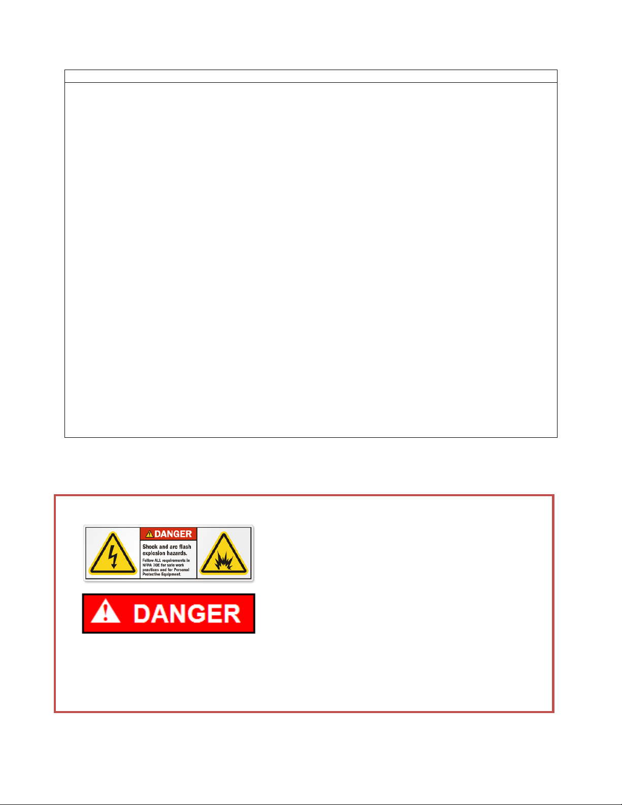
Danger
This indicates a hazardous situation which, if not avoided, results in death or serious injury. A variety of
electrical hazards warnings are displayed here and are applied to installation manuals. These are standard
or generic alerts and labels that must be taken quite seriously when installing Retrofil circuit breakers in AKD
switchgear and when working with potentially dangerous electrical equipment (Table 1). There are also
dangers, pertaining to product safety, that need to be custom-written for particular or specific
circumstances (Table 2).
Table 1. Generic Danger Alerts and Labels Used for Documentation and
Dangerous Equipment
Table 2. Custom Danger
Alerts and Labels Used for
Documentation and Dangerous
Equipment
Page 5
4 EntelliGuard R Circuit Breaker Retrofill AKD-8 Installation Manual DEH-41549 02/12
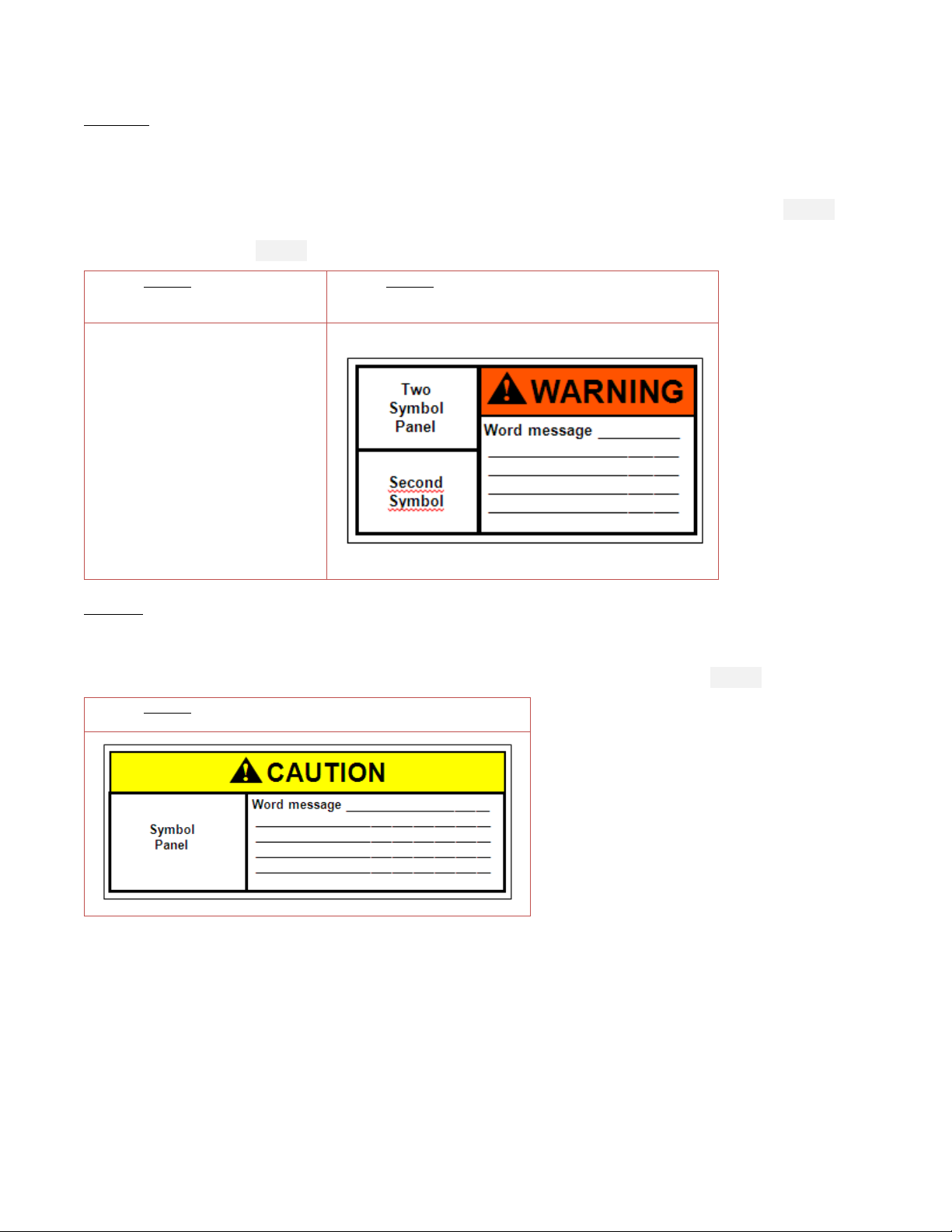
Warning
This indicates a hazardous situation, which, if not avoided, would result in death or serious injury. A variety of
electrical hazards warnings are displayed here and are applied to installation manuals. These are standard
or generic alerts and labels that must be taken quite seriously when installing Retrofill circuit breakers in AKD
switchgear and when working equipment that can cause injury, but may not be necessarily fatal (Table 3).
There are also warnings, pertaining to product safety, that need to be custom-written for particular or
specific circumstances (Table 4).
Table 3. Generic Warning Alerts and
Labels Used for Documentation and
Dangerous Equipment
Table 4. Custom Warning Alerts and Labels Used for
Documentation and Dangerous Equipment
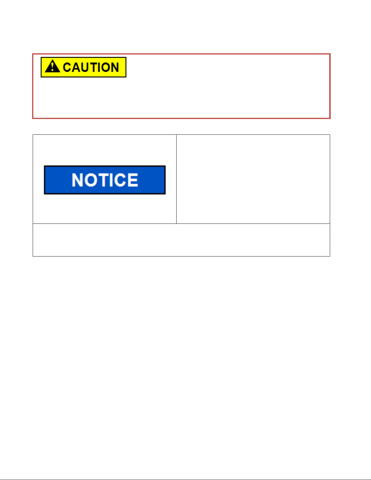
Caution
This pertains to a hazard that has a low level of risk, which means that if not avoided, it could result in minor
or moderate injury. It also indicates that failure to comply with instructions may result in product damage.
The label here requires a specific message that targets a special product or procedure (Table 5).
Table 5. Custom Caution Alerts and Labels Used for Documentation
and Operating Equipment
Page 6
5 EntelliGuard R Circuit Breaker Retrofill AKD-8 Installation Manual DEH-41549 02/12
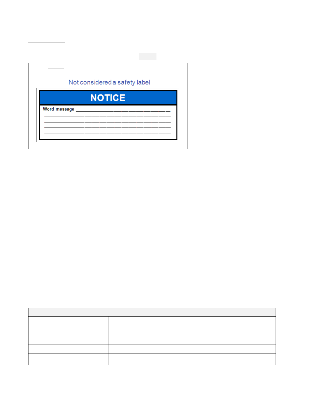
Notice or Note
This indicates important information in that it aids in job performance, that is, a notice or note is used to
notify practices not related to personal injury (Table 6).
Table 6. Custom Notice Alerts and Labels Used for Documentation and
Operating Equipment
Warranty
This document is based on information available at the time of its publication. While efforts have been made
to ensure accuracy, the information contained herein does not cover all details or variations in hardware and
software, not does it provide for every possible contingency in connection with installation, operation, and
maintenance.
Features may be described herein that are not present in all hardware and software systems. GE Energy
assumes no obligation of notice to holders of this document with respect to changes subsequently made. GE
Energy makes no representation or warranty, expressed, implied, or statutory, with respect to, and assumes
no responsibility for the accuracy, completeness, sufficiency, or usefulness of the information contained here
it. Not warrantees of merchantability or fitness for purpose shall apply.
Contact your local sales office if further information is required concerning any aspect of EntelliGuard R
Circuit Breaker operation or maintenance.
Trademarks and Patents
EntelliGuard® R
EntelliGuard
®
TU
EntelliGuard
®
TripUnit
EntelliGuard
®
G
Standards
Agency Certification
Standard Number
Title
ANSI C37,13,16,17,20,50
Low-Voltage AC Power Circuit Breakers
NEMA SG 3,5
Low-Voltage Power Circuit Breakers
NEMA AB1
--
UL 1066
Low-Voltage AC and DC Power Circuit Breakers Used in Enclosures
Page 7
6 EntelliGuard R Circuit Breaker Retrofill AKD-8 Installation Manual DEH-41549 02/12
Document Conventions
Topics and text are divided into primary, secondary, and tertiary paragraph headings.
Related Publications
Publication
Publication Number
Brochure
DEA-532
Snapshot
DEE-543
Installation Manual AKD8
DEH-41549
Installation Manual AKD6
DEH-41548
Installation Manual AKD5
DEH-41547
Accessory: Door Interlock (Door Interlock Kit)
DEH-41529
Accessory Retrofill Doors Assembly
DEH-41563
Accessory: Position Switch Plate & Position Switch Assembly & Wiring (Position Switch Kit)
DEH-41530
Accessory: Neutral Rogowski CT Disconnect (Neutral Assemblies)
DEH-41531
Accessory: Programmer Disconnects
DEH-41532
Accessory: Finger Clusters (Cluster Assemblies)
DEH-41533
Accessory: Secondary Disconnects
DEH-41534
FAQ
DEQ-171
Application Guide
DET-753
Guideform Spec
DET-754
Spare/Renewal Parts Guide
DET-755
Service and Support
Service and support always available from GE Energy.
Estimated Time to Complete Tasks
It takes about 20 minutes to install the assembly, but the time for replacing neutral CT in the switchgear does
not include the 20-minute timing claimed for the roll-in replacement.
Description
Product Specs
Weight (lbs)
Retrofill Breaker
Weight
Box Weight 10101653P1
Pallet 10101650P1 Wt
Accessories
Wt
Total
Weight
AKR30S
184
16
33
2
235
Retrofill Breaker
Weight
Pb2 Large Frame Box Wt
10101653P1
Pallet 10101513P1 Wt
Accessories
Wt
Total
Weight
AKD8
277
18
33
2
330
Retrofill Breaker
Weight
Box Weight 10101655P1
Pallet 10101650P1 Wt
Accessories Wt
Total
Weight
AKR30S
184
11
24
2
221
AKD8
277
11
24
2
314
Page 8
7 EntelliGuard R Circuit Breaker Retrofill AKD-8 Installation Manual DEH-41549 02/12
Views
General Electric AKD-8 Low Voltage Switchgear is a free-standing assembly of metal-enclosed units of power
circuit breakers and other auxiliary power circuit protective devices. It may also be a part of a single-ended
or double-ended load center unit substation. It’s defined as a draw-out breaker. Figure 1 (front and back
views with finger clusters) presents an AKD-8 EntelliGuard R Retrofill breaker, permanently encased in a
cassette-like structure.
Figure 1. AKD-8—AKR30H\50H Breaker in Cassette (Front View)
The EntelliGuard R Circuit Breaker is suitable for application on power systems up to 635 VAC 50/60 Hz
systems and up to 1000 Vdc as a main/source breaker, feeder breaker, bus coupler, or tie breaker.
History and Types
AKD
AK — Power Circuit Breaker Equipment
D — Drawout circuit breaker construction
Manufactured from 1951 to 1975, the breakers had these characteristics:
• All bolted
• Copper bus design
• All drawout-breakers—AK-1, —2, —3,—15 / 25 / 50 / 75 / 100
• 4000A-max bus rating
• 4 levels of bus
• Ring-bus used in all feeder sections
• Main bus with provisions for future extension
• Sections in outdoor construction, which did not line up in the front
• Indoor construction, with extended frames, allowing the section fronts to line up
• Indoor depths of 49" (225 / 600A breakers)
• Indoor depths of 59" (1600A breakers)
• Indoor depths of 63" (3200 / 4000A breakers)
Back then, breakers had a ratcheting drawout mechanism, with an open-door drawout. Breakers were
painted ANSI 61, light gray, manufactured in Philadelphia from 1951 to the mid-60s and in Burlington from
the mid-60s to 1975.
The breaker compartment was a welded assembly, and the equipment frame was bolted. Breaker boxes
were stacked to make a vertical section with equipment frame around the breaker boxes. There were no bus
compartment barriers, just an open bus design. Ring silver-plating was applied to bolted connections.
Page 9
8 EntelliGuard R Circuit Breaker Retrofill AKD-8 Installation Manual DEH-41549 02/12
AKD-8—AKR30H, AKR30L, AKR50H, AKR30S
The AKD-8 was produced from 1981 to 1999. Models 1 and 2 have extruded vertical buses. Model 2 was
introduced in 1983 to accommodate automated wiring programs and harness routing. Model 3 was
introduced in 1991, using a flat bar, vertical bus. AKR breakers use MicroVersaTrip 9, RMS9, EPIC, MVT Plus,
MVT PM trip-units. The aluminum bus was removed from design in 1996 in favor of the standard
tin-plated, copper bus (silver plating optional). Field convertible space compartment design was added to
allow empty compartments to be modified for functioning breaker compartments without modifying the
vertical bus.
AKD-8—Retrofilll Breaker
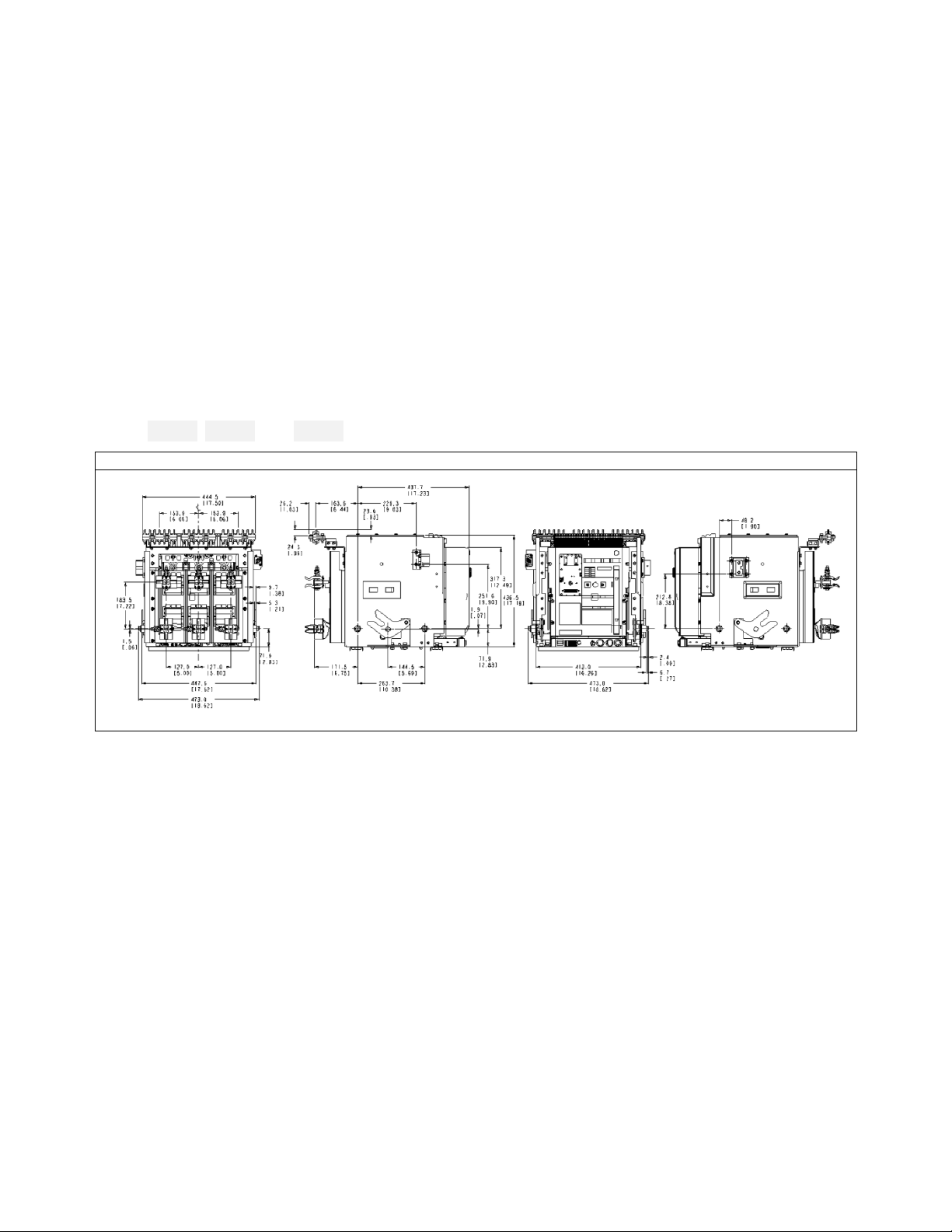
AKD-8—Mechanical Drawings
The following engineering or assembly drawings describe the layout and dimensions of the AKD-8 Retrofilll
breaker (DWG 1, DWG 2, and DWG 3).
DWG 1. AKD-8—AKR30/30H—Retrofill Breaker, Dimensioning
Page 10
9 EntelliGuard R Circuit Breaker Retrofill AKD-8 Installation Manual DEH-41549 02/12
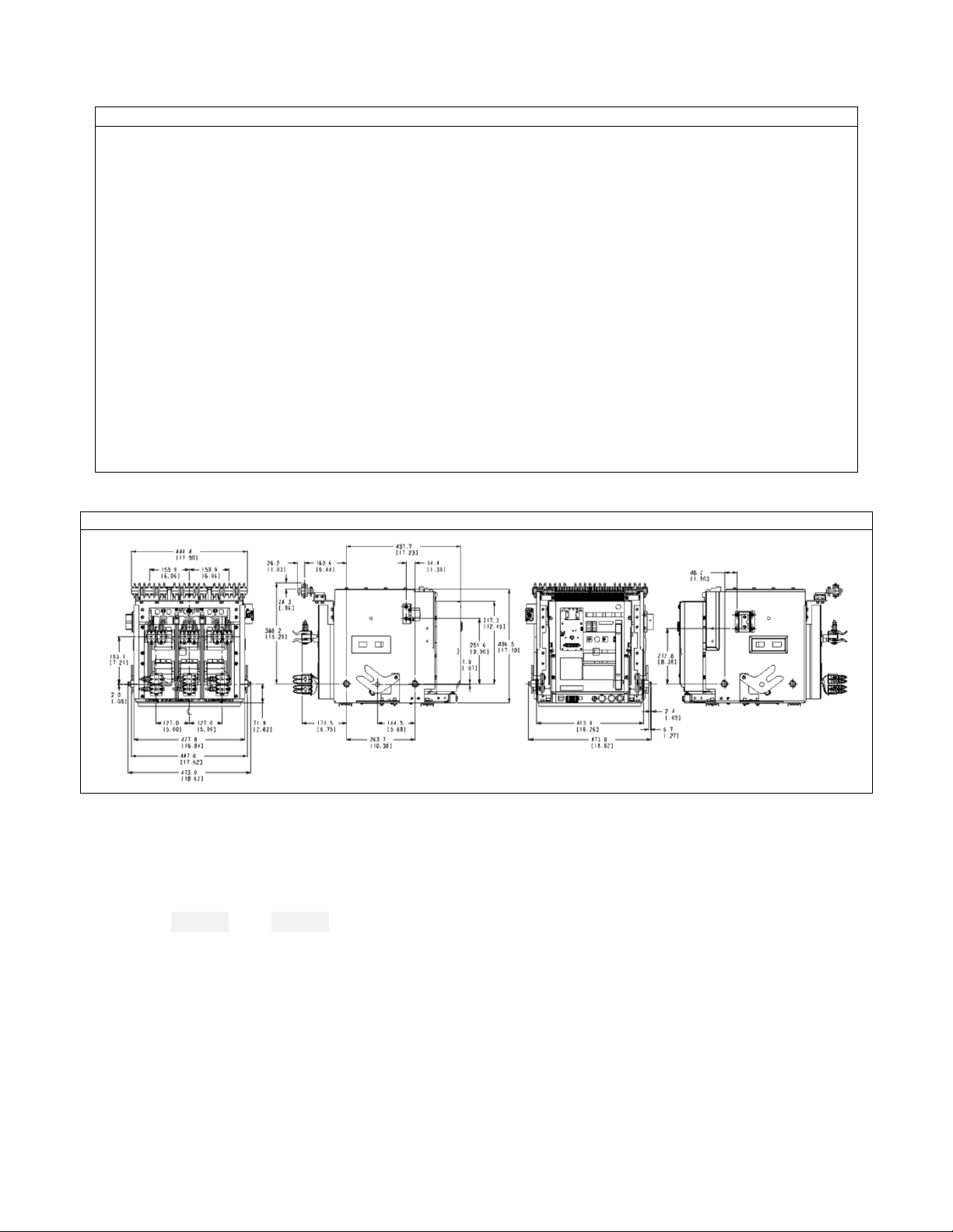
DWG 2. AKD-8—AKR30S—Retrofill Breaker, Dimensioning
DWG 3. AKD-8—AKR50/50H/30L—Retrofill Breaker, Dimensioning
AKD-8 Compartment
Interior View
The figures (Figure 2) and (Figure 3) below present a new AKD-8 compartment, with one photo showing the
rails extended.
Page 11

10 EntelliGuard R Circuit Breaker Retrofill AKD-8 Installation Manual DEH-41549 02/12
Figure 2. AKD-8—(new) Empty Lower Compartment, View 1
Figure 3. AKD-8—(new) Empty Lower Compartment, View 2,
Racks/Rails Extended
Figure 4 is a photo of the interior of the AKD-8. The photos point out the shutter assembly and telescopic rails
in the AKD-8.
Figure 4. AKD-8—Compartment Assemblies
Interior Components
Figure 5 points out the major components of an AKD-8 compartment.
Page 12
11 EntelliGuard R Circuit Breaker Retrofill AKD-8 Installation Manual DEH-41549 02/12
Figure 5. AKD-8—Circuit Breaker Compartment (22-Inch) for AKR-30/50/T50 Breakers
Unpack CB
• Turn off all power to switchgear. Tagout
and lockout main source, up-stream or main
breaker.
• Failure to comply with these instructions
will result in death or serious injury from
severe burns caused by arc flashing that has
exceedingly high temperatures.
• Always wear personal protection equipment
according to OSHA standards and
appropriate to the severity of potential
burns.
• Ensure only qualified personnel install, operate, service, and maintain all electrical
equipment.
Page 13
12 EntelliGuard R Circuit Breaker Retrofill AKD-8 Installation Manual DEH-41549 02/12
Falling Object
• Do not walk or remain under any heavy assembly while
hoisted above head as the chains securing the
assembly may give way
• Ensure lifting equipment has capability for device being lifted.
• Wear hard hat, gloves, and safety shoes.
• Failure to comply with these instructions could result in serious injury.
PRODUCT DAMAGE
• Ensure circuit breaker and its accessories
are always used within their designated
ratings.
• Do not allow the circuit breaker to hit a
hard surface while handling.
• Do not drag or slide the circuit breaker
across a hard or rough surface
• A factory-installed rejection feature prevents mismatching circuit breakers and cassettes/
substructure, preventing the insertion of a circuit breaker with a lower rating into a higher rated
cassette/substructure, or the insertion of a higher rated circuit breaker into a lower rated
cassette/substructure.
By following the procedures below, you should be able to install the breaker with minimum effort
and time.
Quality Assured
All EntelliGuard R circuit breakers have been designed and manufactured to the highest technical standards.
Strict procedures ensure first class product quality.
Information Check Sheet
On the side wall of each circuit breaker there is a detailed factory-assembled, side label that details all
features included on both the circuit breaker and on the trip unit.
Product and Catalogue Serial Numbers
Product and catalogue serial numbers should be kept handy when communicating about the circuit breaker.
Each circuit breaker has a unique serial number located on the left side (viewed from front) of the front
fascia.
Environmental Conditions
This indicates failure to comply with these instructions may result in product damage.
Page 14

13 EntelliGuard R Circuit Breaker Retrofill AKD-8 Installation Manual DEH-41549 02/12
Remove Circuit Breaker from Container
Inspect
1. Inspect the shipping container for obvious signs of rough handling and/or external damage incurred
during transportation.
2. Record any observed damage for reporting to the carrier. Ensure all recorded reports and claims include
the order number and name plate information.
3. Remove the banding straps and lift the top cover.
4. Remove all packaging material.
5. Remove all product documentation and store properly.
6. Unscrew the mounting screws that fasten the circuit breaker to the bottom of the shipping palette and
remove the circuit breaker.
Use Lifting Truck
1. Use a lifting truck to lift and mount the assembly so that you can avoid personal injury and damaging the
breaker (Figure 6).
2. Contact the nearest sales office for availability of a hoisting device.
3. Avoid using hooks and chains since hooks can damage the fascia of the circuit breaker.
Figure 6. AKD-8—On Lifting Truck or Fork Lift (with Some CB Assemblies Identified)—AKR30S (left) and AKR30H (right)
Page 15

14 EntelliGuard R Circuit Breaker Retrofill AKD-8 Installation Manual DEH-41549 02/12
Store Circuit Breaker
PRODUCT DAMAGE
• Do not store circuit breaker in corrosive
environments above LC1 (sea salt mist) and
G1 as per ANSI/ISA-S71.04-1985.
• Ensure circuit breakers and cassettes are
stored in a clean, dry location, in their
original packaging.
• Failure to comply with these instructions
may result in product damage.
If you decide not to install the Retrofilll breaker until a later time, then you can store it away for installing
it later.
1. Store the circuit breakers in a clean, dry location in an upright position.
2. Make sure that the breakers are properly supported to prevent bending of the studs or damage to
any of the breaker parts. Do not remove any protective grease until the assemblies are ready to be
installed. A covering of draft or other non-absorbent paper prevents dust from settling on the breakers.
3. If breakers are not to be placed in service at once, remove them from their shipping cartons and
thoroughly inspect them.
4. If everything is in satisfactory condition, replace the breakers in their shipping cartons for storage. Do not
move the shipping members at this time. If it is necessary to store the equipment for any length of time,
do the following precautions to prevent corrosion or deterioration:
• Uncrate the equipment and check thoroughly for damage.
• Store in a clean, dry, rodent-free location with moderate temperature and provide protective
coverings to prevent dirt, water, or other foreign substances from entering the breaker.
• If dampness or condensation is encountered in the storage location, heaters for circuit breakers in a
closed environment can be used to prevent moisture damage.
Page 16

15 EntelliGuard R Circuit Breaker Retrofill AKD-8 Installation Manual DEH-41549 02/12
Check Before Installing
• It must be ensured that the supply power to
the compartment is turned off/ compartment
is de-energized for all the incoming and
outgoing circuits of the LVS prior to any work
being conducted on it.
• During the installation and related work on
the equipment, it must be ensured that the
operator is using the prescribed PPE for the
specified tasks.
• Ensure only qualified personnel install, operate, service, and maintain all electrical
equipment.
These breakers are supported on a rollout track in the same manner as the AK breakers. However, since the
rack-out mechanism is mounted on the breaker, there are no jackshafts in the enclosure. Racking arms on
both sides of the breaker frame engage the drawout mechanism pins fastened to both sides of the
compartment.
1. Check to see that the breaker or breakers match their respective compartments. Each breaker is
assigned a part or mark number.
2. Look on the breaker sheets summaries, the front view drawings, breaker nameplate, and on the
identification card on the breaker shipping carton.
3. To locate the breaker for its proper compartment, refer to the breaker location list on the front view
drawing. Find the proper breaker by the identification card on the breaker carton, or the mark number
on the breaker nameplate. All identical breakers have the same mark number.
Clean and Grease Breaker
1. Before installing or operating a breaker, refer to the breaker instruction manual for pre-operation
inspection and test.
2. Check thoroughly for any damaged or loose parts and for any dirt or foreign matter which may be in
the breaker.
3. Clean those areas if necessary with a clean, lint-free rag and isopropyl alcohol or acetone.
4. Be sure to apply a thin film of electrical grease (red, D50H47) to the contact areas (fingers) for better
electrical connections on the breaker (Figure 7).
Page 17

16 EntelliGuard R Circuit Breaker Retrofill AKD-8 Installation Manual DEH-41549 02/12
Figure 7. AKD-8—Primary Contacts or “Fingers” (Apply Grease)
Page 18

17 EntelliGuard R Circuit Breaker Retrofill AKD-8 Installation Manual DEH-41549 02/12
Modify Retrofill
WIRING
• Before installing the breaker, the
secondary disconnects must be wired to
the EntelliGuard Breaker.
• Wires with wire markers are provided on
the retrofil. Make sure that the switchgear
wiring connection points match up with
the original wiring of the cubicle. This
ensures that all wiring connections are
properly made.
• Wrong connections will cause the breaker
to malfunction.
Modify AKD-8—AKR30S Switchgear Compartment, Only
• It must be ensured that the supply power
to the compartment is turned off/
compartment is de-energized for all the
incoming and outgoing circuits of the LVS
prior to any work being conducted on it.
• During the installation and related work on
the equipment, it must be ensured that the
operator is using the prescribed PPE for the
specified tasks.
• Ensure only qualified personnel install, operate, service, and maintain all electrical
equipment.
Page 19

18 EntelliGuard R Circuit Breaker Retrofill AKD-8 Installation Manual DEH-41549 02/12
AKD-8—Remove Glastic Sheet
Figure 8. Remove Glastic Sheet
The AKD-8 AKR30S switchgear compartments (22" by 30" by 38") need this particular attention. The glastic
sheet has to be removed (Figure 8).
In some cases, however, it is possible that this sheet is not secured to the top of the cabinet properly, and
was found to sag around the middle of the cabinet. This could lead to the sheet interfering with secondary
disconnects. Removing the glastic sheet does not require any tools, but you need to exercise the caution
while removing the glastic sheet to avoid contact with compartment mounted secondary disconnects. After
removing the glastic sheet, discard it.
AKD-8—Modify Bracket
• It must be ensured that the supply power to
the compartment is turned off/
compartment is de-energized for all the
incoming and outgoing circuits of the LVS
prior to any work being conducted on it.
• During the installation and related work on
the equipment, it must be ensured that the
operator is using the prescribed PPE for the
specified tasks.
• Ensure only qualified personnel install, operate, service, and maintain all electrical
equipment.
Page 20

19 EntelliGuard R Circuit Breaker Retrofill AKD-8 Installation Manual DEH-41549 02/12
Figure 9. Modify Bracket
Steps for removing the bracket pin:
1. Remove the left bracket assembly (75C149309G061) from compartment (Figure 9). The assembly is
bolted to the side sheet. Four fixing bolts assembled can be removed by the service technician. For this
task, a socket head wrench or a normal wrench, used for fastening hex bolts, is required.
2. Remove the pin from the bracket (75A106208P204). The pin is riveted from the inside and has to be
drilled from the same side. Removing the bracket is necessary.
3. Note that assembly must be done by a trained service technician only.
4. Apply corrosion resistance treatment to the exposed metal after removing the pin.
5. Reassemble the bracket assembly and scrap or discard the pin.
Install AKD-8—Retrofilll
• It must be ensured that the supply power to
the compartment is turned off/
compartment is de-energized for all the
incoming and outgoing circuits of the LVS
prior to any work being conducted on it.
• During the installation and related work on
the equipment, it must be ensured that the
operator is using the prescribed PPE for the
specified tasks.
• Ensure only qualified personnel install, operate, service, and maintain all electrical
equipment.
After the existing breaker is removed and the compartment modified, the pre-wired Retrofilll breaker can
now be installed in the AKD-8 switchgear.
Page 21

20 EntelliGuard R Circuit Breaker Retrofill AKD-8 Installation Manual DEH-41549 02/12
1. Verify that the breaker is in the disconnected, switched-off position before mounting it on rails.
2. Pull out the cubicle rails, horizontal to the ground.
3. While rotating the lever (away from the cubicle) at the end of each rail, which unlocks the inner rail, pull
the rail assemblies outwards to their fully extended positions. The rails can now support and secure the
Retrofilll breaker in the switchgear.
4. Get a hand-crane and wheel it over to the breaker (or use a forklift, Figure 10 and Figure 11). This might
need a two-man effort: one to carefully and slowly lower the boom with the suspended breaker and the
other to guide the breaker into the switchgear enclosure.
Figure 10. AKD-8—Using a Forklift, AKD-8 CB, Front View
Figure 11. AKD-8—Using a Forklift, AKD-8 CB, Top View
5. Lower the boom of the lifting device so that you have enough slack to insert its two hooks in the
breaker’s lifting holes. Or attach a lifting bar between the two holes eye bolt provided with the circuit
breaker, instead of hooks.
6. Make sure that the crane lifting hooks are secured and locked in place on the breaker if the fork lift is not
being used.
7. Using the hydraulic lift, raise the breaker slowly so that it clears the breaker platform. Suspend the
hoisted breaker a yard off the ground or floor. Carefully wheel crane, with hoisted breaker, over to the
switchgear for installation.
8. Line up the breaker in front of the unit in where it is to be installed, leaving enough clearance to
maneuver the Retrofill.
9. Check that the Retrofilll is free from obstruction inside the compartment.
10. When the breaker is lined up with the compartment, raise the breaker only slightly higher than the
compartment floor, keeping it at a slight angle.
11. Keep the breaker steady. Continue to guide the breaker, while checking both sides and underneath, so
that both sets of pins can be lowered and lined up easily with the rails’ slots.
12. Place retrofit EntelliGuard R Retrofill breaker on the rails to the disconnect position of the legacy breaker.
(Note that the pins must line up with the slots on the rails.)
13. As soon as the breaker is resting on the rails, unhook the lift hooks from the ears or holes of the circuit
breaker. Move the hoisting apparatus out of the way.
Page 22

21 EntelliGuard R Circuit Breaker Retrofill AKD-8 Installation Manual DEH-41549 02/12
14. Lock the rails of the legacy compartment to ensure inner and outer rail movement. This will help secure
the Retrofill EntelliGuard into the compartment.
15. Remove the racking tool (Figure 12) from the storage location on the Retrofilll front panel and grab
the handle.
Figure 12. AKD-8—Racking Tool
16. Take a blade-type screwdriver, insert it in the slot or rack-out lock of the breaker (Figure 13), and turn it
clockwise 45° to the right so that the racking handle shutter, inside and behind the racking hole, also
moves to the right.
Figure 13. AKD-8—Racking Tool and Screwdriver Inserted
Inserting the racking handle:
• First, insert a blade screwdriver in
the righthand slot and rotate it 45°
to the right.
• Then, while holding the
screwdriver torqued to the right,
insert the racking tool in the left
slot until it engages with the
machanism inside.
• After the racking tool engages,
remove the screwdriver.
17. After turning the screwdriver to the right with the shutter sliding to the right, remove the screwdriver and
insert the racking tool (Figure 13) in the handle-insertion hole. It’s located on the left side. Insert this tool
so it that grabs or engages the racking mechanism inside the hole. Once the racking tool has been
properly engaged, the screwdriver can be disengaged.
18. Line up the racking tool or crank with the handle straight up so that you can get some good leverage or
torque. Then, crank clockwise so that the Retrofilll starts to move in, slowly sliding forward into the
compartment. Rotating clockwise racks the circuit breaker all the way into the enclosure.
19. As the breaker approaches the TEST position, check the alignment of the fixed and moving parts of the
secondary circuit isolating contacts.
20. Continue to rack in the breaker using the Entelliguard racking handle. Continue rotating the racking
handle clockwise until the position indicator first shows TEST, then CONNECTED.
Page 23

22 EntelliGuard R Circuit Breaker Retrofill AKD-8 Installation Manual DEH-41549 02/12
21. When approaching the CONNECTED position, effort to turn the racking handle increases as the clusters
engage with the compartment/cabinet-mounted contacts. If a motor spring charge or under voltage-torelease is installed, these may operate when approaching the TEST position.
22. Keep cranking as required, that is, when any further torqueing can’t be done. At this point, the
fingers at the back of the circuit breaker have completely grabbed onto the contacts at the back of the
cassette.
23. Remove and store the racking handle in it storage location. It is a good idea to keep the racking handle
always in the same place for future use.
AKD-8—Racked-In
The photo below show only one example of a racked-in AKD-8 Retrofill (Figure 14).
Figure 14. AKD-8—AKD-8 Racked-In CB
Page 24

23 EntelliGuard R Circuit Breaker Retrofill AKD-8 Installation Manual DEH-41549 02/12
AKD-8—Install Accessories
WIRING
• Before installing the breaker, the
secondary disconnects must be wired
to the EntelliGuard Breaker.
• Wires with wire markers are provided
on the retrofil. Make sure that the
switchgear wiring connection points
match up with the original wiring of the
cubicle. This ensures that all wiring
connections are properly made.
• Wrong connections will cause the
breaker to malfunction.
AKD-8—Secondary Disconnects, Bullets
This section deals with installing and wiring the legacy secondary disconnect assemblies onto the Retrofill
EntelliGuard ACB. Installing the secondary disconnect assembly consists of doing these tasks:
• Installing the secondary disconnect assembly (bullets, shown in Figure 15, below)
• Wiring the secondary disconnect assembly (bullets, shown in Figure 15, below)
The Retrofill EntelliGuard ACB has these two options:
• All secondary disconnects installed
• No secondary disconnects installed
In case the application requires installing all 3 secondary disconnect blocks (actually, three sets of bullets),
you would select the first option. As secondary disconnects can be pre-installed on the breaker, wiring the
secondary disconnects can be done.
In case the application does not
require any secondary disconnect assemblies, take the second option. Thus,
no further wiring is needed.
If the application requires less than 3 secondary disconnect blocks, the customer can choose the second
option, order the secondary disconnect blocks as needed, and then install the secondaries, completing the
wiring for the Retrofill EntelliGuard ACB. These options are discussed in the next sections.
Secondary Disconnect Assemblies
P/N 10105366G1
Retrofill Sec Disc Assy AKR
AKD8
P/N 10099265G2
FIXED SD ASSEMBLY
AKD8
Page 25

24 EntelliGuard R Circuit Breaker Retrofill AKD-8 Installation Manual DEH-41549 02/12
Figure 15. AKD-8—Seven Bullets to a Block, Three Blocks
Entelliguard ACB secondary disconnect system:
Procedures
Figure 16. AKD-8—Seven Bullets to a Block, Three Blocks (Exploded View)
Along with this the secondary disconnect block assemblies (Figure 16, above) for the AKD8 version of the
EntelliGuard Retrofill ACB can be purchased and installed. Here’s how to install:
1. Unpack the secondary disconnect block from the box. The kit comes in just one box. Each kit of
secondary disconnect has 4 fixing nuts, plain washers, and spring washers. These can be arranged on a
work station for preparing to install the secondary disconnect blocks.
2. Check that the bullets, on top of the secondary disconnects, are not damaged and that they are freely
sliding in and out of their individual cylindrical cells, block-by-block. The bullets are spring-loaded and
retracts to their initial positions if they are released from their pressed conditions. It is recommended that
all 21 bullets be tested. Normally, just a visual check is enough for checking non-functioning bullets.
Page 26

25 EntelliGuard R Circuit Breaker Retrofill AKD-8 Installation Manual DEH-41549 02/12
3. Check for electrical continuity between the bullets on one end and the wire terminations on the other. In
other words, a wire provides the electric connection between the secondary disconnects of the legacy
bullets and the secondary disconnects on the EntelliGuard ACB. A multimeter may be used.
4. Replace bullet blocks that are found with faulty bullets. Even with only one non-working bullet, replace
the whole
block of bullets.
5. Place the secondary disconnect block on top of the horizontal plate at the rear of the Retrofill
EntelliGuard ACB, which runs across the width of the Retrofill EntelliGuard ACB.
6. Allign the 4 studs at the base of the supplied block to the 4 holes on the said plate. The plate is provided
with 3 sets 4 of holes, one each for A, B, and C blocks respectively.
7. Slide the secondary blocks down into the plate such that the base of the secondary disconnect rests on
top of the plate.
8. Secure the studs on to the fixing plates using the hardware provided as mentioned above. The nuts must
be tightened handtight.
9. Check that the wire markers are clearly visible and not damaged so that wiring connections are done
correctly and easily (Figure 17 and Figure 18).
WIRING
• Do not pinch/damage the wires while
installing the secondary disconnect
blocks.
Figure 17. AKD-8—Seven Bullets to a Block, Three Blocks to a Retrofill (Photo View)
Page 27

26 EntelliGuard R Circuit Breaker Retrofill AKD-8 Installation Manual DEH-41549 02/12
Figure 18. AKD-8—Landed Wiring (Photo View)
Wire Secondary Disconnect Assembly—AKR30/30H/50/50H/30L/30S
As mentioned above, the secondary disconnect blocks are available with all blocks installed. In this case, the
wires on the blocks will be routed through one side of the breaker and on the front. The wires on the front are
left loose for ease of landing the wires to the EntelliGuard ACB breaker secondary disconnects.
If the secondary disconnect blocks are installed at the customer site, the wires will not have been routed. The
wires should not be routed from the outside of the metal structure as it might interfere with the motion of the
kit during the racking into the compartment. Also, it should be ensured that the wires are securely fixed on
the inside metal frame of the Retrofilll kit using sticky pads and tie-wraps.
Verify that the the wire routing is not exerting pressure on bullets because this can bend the connection
points and effect biasing and contact pressure. By using tie-wraps and stickpads, wire routing can eliminate
sagging of the wire harness and pressure on secondary bullets.
Once the above mentioned steps are completed, landing of the wires to the points on the EntelliGuard ACB
secondaries can begin, based on the typical wiring diagrams found in Figure 19 and Figure 20.
Figure 19. AKD-8—Secondary Disconnects Wiring Diagram (Example for AKR30/30H/50/50H/30L)
Figure 20. AKD-8—Secondary Disconnects Wiring Diagram (Example for AKR30S)
• Tools needed: Philips Head screw driver, M6 spanner, wire strippers, wire cutters.
Page 28

27 EntelliGuard R Circuit Breaker Retrofill AKD-8 Installation Manual DEH-41549 02/12
AKD-8—Programmer Disconnects
WIRING
• Before installing the breaker, the
secondary disconnects must be wired
to the EntelliGuard Breaker.
• Wires with wire markers are provided
on the retrofil. Make sure that the
switchgear wiring connection points
match up with the original wiring of the
cubicle. This ensures that all wiring
connections are properly made.
• Wrong connections will cause the
breaker to malfunction.
The programmer disconnect consists of 2 assemblies, one mounted on the breaker side and the other
mounted on the cabinet. The breaker side assembly consists of the mounting bracket and plug assembly.
The compartment side assembly consists of the plug assembly mounted on a spring-loaded assembly that
receives the breaker.
WIRING
• Note: Look for the wiring connection
scheme on the existing or old terminal
block and use the same references or
wiring info while re-wiring the new
terminal block..
Procedures
1. Identify the existing programmer disconnect assemblies in the compartment.
The existing programmer disconnect plugs used in AKD-8 generation of the AKR breakers are provided
on the right side for the AKR30/30H/50/50H/30L and on the left side for the AKR30S retrofits.
Programmer disconnects are provided with legacy AKR breakers in AKD-8 LVS. The breakers were
equipped with the following pin configurations, depending on the application:
• 9-pin configuration
• 12-pin configuration
• 24-pin configuration
Page 29

28 EntelliGuard R Circuit Breaker Retrofill AKD-8 Installation Manual DEH-41549 02/12
2. Identify the type of programmer disconnect assemblies to be installed with retrofit kit.
The programmer disconnect assembly to be assembled depends upon the type of breaker the retrofil is
replacing. These are as follows:
• AKR30/30H/50/50H/30L—In these, the programmer disconnect is mounted on the left side wall of the
retrofil.
• AKR30S—In these, the programmer disconnect is mounted on the right side wall of the retrofil.
Programmer disconnect assemblies are available in two configurations for the Retrofill EntelliGuard ACB,
namely:
• 12-pin configuration—If the legacy LVS has a 12-pin programmer disconnect in use, the same can be
used with the Retrofill EntelliGuard ACB. In this case, only the breaker side programmer disconnect
assembly on the breaker needs to be installed. The numbers for the programmer disconnects are
mentioned below.
12-Pin Programmer Disconnect Breaker Side
P/N 10105385G1
PROG.DIS.ASSY, AKD8
AKR30H/ 50H AKD8
P/N 10105651G1
PROG. DIS. ASSY
AKR30S
19-Pin Programmer Disconnect Breaker Side
P/N 10108733G1
PROG.DIS.ASSY, AKD8
AKR30H/ 50H AKD8
P/N 10108732G1
PROG.DIS.ASSY, AKR30S
AKR30S
• 19-pin configuration—If the legacy LVS doesn’t have a 12-pin programmer disconnect configuration,
and the customer chooses to install a programmer disconnect, then the 19-pin programmer
disconnect assembly needs to be installed in the compartment and the breaker.
19-Pin Programmer Disconnect Breaker Side
10108733G1
PROG.DIS.ASSY, AKD8
AKR30H/ 50H AKD8
10108732G1
PROG.DIS.ASSY, AKR30S
AKR30S
19-Pin Programmer Disconnect Compartment Side
10108801G1
PROGRAMMER DISC ASSY
AKR30H/ 50H AKD8
10109176G1
PROGRAMMER DISC ASSY
AKR30S
3. If applicable, remove the existing compartment side programmer disconnect assembly.
The programmer disconnect assembly must be removed, if:
• A 9-pin programmer disconnect assembly is installed in the cabinet.
• A 24-pin programmer disconnect assembly is installed in the cabinet.
• Customer chooses to replace a 12-pin configuration with a 19-pin configuration.
4. Before uninstalling the existing programmer disconnect assembly, verify that the wiring details are
match the wiring numbers. Any changes or deviations need to be noted for use while installing the new
programmer disconnect.
5. Check that the compartment is de-energized and is safe to work in; and that the original or legacy
breaker has been removed form the cabinet.
6. Disconnect the wires connecting the terminal block to the compartment programmer disconnect
assembly. See Figure 21.
Page 30

29 EntelliGuard R Circuit Breaker Retrofill AKD-8 Installation Manual DEH-41549 02/12
7. If the customer has chosen to install a 19-pin programmer disconnect assembly, replacing a 12-pin
programmer disconnect assembly, the terminal block mounted on the compartment needs to be
removed as well. This can be achieved by unfastening the two screws securing the terminal block with
the side wall of the compartment.
8. Unfasten the four bolts included that the that hold the programmer disconnect assembly on the wall of
the compartment to remove the compartment-side programmer disconnect assembly.
Figure 21. AKD-8—Loosen Hardware for the Programmer Disconnect Assembly
9. Install applicable programmer disconnect assembly on compartment and breaker.
• Wiring and completing task:
Install 19-pin programmer disconnect assembly on compartment and breaker:
1. Unpack the 19-pin programmer disconnect assembly from the box. Each box of the programmer
disconnect assemblies has a 20-pin terminal block supplied.
2. Check that the secondary disconnect plug assembly is not damaged and the wiring is intact.
3. Check that the programmer disconnect block is moving freely within the assembly and retracts to its
original position by spring-loading when it is slid back to the fully activated condition.
4. Check for electrical continuity between the contact pins on one and and the wire termination on the
other. Blocks containing faulty bullets should not be used for installation.
5. Install the new terminal block on the side wall of the the compartment and land the incoming wires from
the compartment to the terminal block. Any additional wires from the compartment side which
are
required for the 19-pin programmer need to be landed on the terminal block and checked for electrical
continuity.
6. Mount the programmer disconnect assembly on the side wall of the compartment where the original
programmer disconnect assembly was mounted.
7. Land the wires from the programmer disconnect to the terminal block mounted earlier.
8. Using a multimeter, check for continuity between the terminal block contact points to the corresponding
pins on the programmer disconnect. This should match against the wiring scheme planned for the new
19-pin programmer disconnect assembly on the compartment.
Page 31

30 EntelliGuard R Circuit Breaker Retrofill AKD-8 Installation Manual DEH-41549 02/12
Wiring and Completion
1. Note he breaker side programmer disconnect assemblies come pre-installed and wired from the factory.
So, no action is needed to be done on the breaker.
2. Check that the compartment side programmer disconnect assembly wiring scheme matches that of the
breaker side wiring scheme.
3. See the wiring diagram used for the programmer disconnect as shown here (Figure 22):
Figure 22. AKD-8—Typical Programmer Disconnect Wiring Scheme
Top row—Terminal numbering on programmer disconnect
Bottom row—Terminal numbering for A & B secondary disconnects of the EntelliGuard breaker
• Tools required: wrenches, flat head screw driver, wire stripper, wire cutter, star-type screw driver
AKD-8—Primary Disconnects (Contacts) or “Fingers”
The Accessory Retrofill Doors Assembly manual DEH-41563 covers the primary disconnects or fingers.
The primary disconnects are flexible connections between the breaker line and load terminals and between
the equipment line and load terminals. All primary disconnect fingers are factory-installed and are
assembled on EntelliGuard R Retrofill circuit breakers. Use this instruction sheet if damaged fingers need to
be replaced. It takes about 5 minutes to install a finger cluster, defined as a double pair of fingers on a
breaker.
Figure 23 shows finger clusters or primary disconnects on a retrofill circuit breaker. Figure 24 details the
finger-cluster assembly.
Figure 23. Circuit Breaker Removed, Featuring Primary
Disconnects “Fingers” (Contacts)
Figure 24. Circuit Breaker, Fingers (Some Details)
Page 32

31 EntelliGuard R Circuit Breaker Retrofill AKD-8 Installation Manual DEH-41549 02/12
Remove and Replace
The primary disconnect assembly is factory-adjusted with a gage to apply a 105-lb force to a 1/2-inch thick
copper bar, inserted between the upper and lower fingers. Set this force range, in the field, by tightening the
nuts to set the spring dimension shown in Figure 25. Note that this dimension is measured between the top
of the retainer and the underside of the washer. Also note that no bar is inserted between the fingers when
setting this dimension. Figure 26 calls out cluster components.
Figure 25. Adjustment
Figure 26. Components
1. Using proper safety procedures and wearing required Personal Protective Equipment (PPE), remove
breaker from compartment, and place it on a solid work surface in a well-lit location.
2. To uninstall the primary disconnects, remove the two nuts from one of the long bolts holding the primary
disconnect assembly together.
3. Carefully slide out the bolt while removing the flat washer, spring, bushing, upper retainer, bow-tie
spacers, lower retainer, and fingers from the bottom of the assembly.
4. Do the same for the other assembly bolt and components.
5. Slide off the retainer clips.
6. Take off the main retainer from the stud.
7. Slide the main retainer over the stud.
8. Install eccentric spacer and position spring clips on the stud.
9. Set a pair of bow-tie spacers into a pair of fingers, place a pressure plate retainer over the spacers to
hold them in position, and then turn the subassembly over. Hook them into the main retainer.
10. Slide a long bolt through the hole in the retainer, between the finger, and then through the clip and
eccentric stud spacer.
11. Hold the bottom finger subassembly in place.
12. Place two fingers around the bolt from the top, hooking the fingers into the main retainer. Then place a
bow-tie spacer in each finger and hold them in position with a pressure plate retainer.
13. Place a spring, bushing, and flat washer over the bolt, then secure with the two nuts.
14. Do Steps 7 through 13 for each set of fingers.
Page 33

32 EntelliGuard R Circuit Breaker Retrofill AKD-8 Installation Manual DEH-41549 02/12
15. Adjust the nut to get a spacing of 0.766—0.797 inch between the top of the upper retainer and the
bottom of the flat washer.
16. Tighten the jam nut to lock in the adjustment.
17. Clean finger assemblies, if necessary, with a clean, lint-free rag and isopropyl alcohol or acetone.
18. Be sure to apply a thin film of Mobilgrease 28 (D50HD38) to the contact areas which slide onto the
switchgear stabs (See Figure 27, Step 2). This product is available in a 1-oz tube, GE Part #193A1751P1.
Figure 27 summarizes the steps for working with the primary contacts.
Figure 27. Steps in Exploded Views
Page 34

33 EntelliGuard R Circuit Breaker Retrofill AKD-8 Installation Manual DEH-41549 02/12
Mechanical Views
Figure 28 provides further details.
Figure 28. Fingers or Clusters, Mechanical View, and Notes
Page 35

34 EntelliGuard R Circuit Breaker Retrofill AKD-8 Installation Manual DEH-41549 02/12
AKD-8—Position Switch Actuator
Position switch actuator comes pre-installed on all versions of Retrofill EntelliGuard ACB. Hence, no
installation is required. Retrofills provide the same electrical indication scheme as the legacy breakers (Figure
29).
Compartment Position Switch Assemblies
0343L0881
AKR30S
0343L690G1
AKR30/30H/30L/50/50H
• A customer can choose to install a position switch if it’s not already installed, although this is infrequent,
or the existing assembly is damaged.
Figure 29. Breaker Surfaces Activate Position Switch.
Page 36

35 EntelliGuard R Circuit Breaker Retrofill AKD-8 Installation Manual DEH-41549 02/12
AKD-8—Shutter Actuation
AKD-8 LVS comes installed come with shutter assemblies for protection of the live bus bars. Retrofill
EntelliGuard ACB comes pre-installed with shutter (Figure 30) actuators which operate the opening of the
shutters. Hence, no installation is required. Retrofills provide the same mechanical indication scheme as
legacy breakers.
Figure 30. AKD-8—Breaker Surfaces Activate Shutter
Install Door Interlock System
• It must be ensured that the supply power
to the compartment is turned off/
compartment is de-energized for all the
incoming and outgoing circuits of the LVS
prior to any work being conducted on it.
• During the installation and related work
on the equipment, it must be ensured
that the operator is using the prescribed
PPE for the specified tasks.
• Ensure only qualified personnel install, operate, service, and maintain all electrical
equipment.
Page 37

36 EntelliGuard R Circuit Breaker Retrofill AKD-8 Installation Manual DEH-41549 02/12
Figure 31 shows the components that make up the AKD-8 retrofill door interlocking assembly.
Figure 31. AKD-8—Door Interlocking Components
AKD-8—Key Interlock
After the switchgear equipment is first installed, all necessary interlock keys should be inserted into the
appropriate locks and all spare keys should be placed in the hands of a responsible person. Refer to the key
interlock schematic included in the summary furnished with the equipment. You can then determine the
sequence of operation and correct number of operating keys required. This precaution is necessary since
improper use of spare keys defeats the interlocking scheme. There are many other interlocking lockout and
tag-out combinations. Some use two or more keys.
Door Interlock Assemblies
P/N 75C149377
Door Interlock Assembly
AKD8
P/N 75C149377
Door Interlock Assembly
AKR30s
Page 38

37 EntelliGuard R Circuit Breaker Retrofill AKD-8 Installation Manual DEH-41549 02/12
Modify AKD-8—Switchgear Compartment
Cut Power to AKD-8—Switchgear
• It must be ensured that the supply power to
the compartment is turned off/
compartment is de-energized for all the
incoming and outgoing circuits of the LVS
prior to any work being conducted on it.
• During the installation and related work on
the equipment, it must be ensured that the
operator is using the prescribed PPE for the
specified tasks.
• Ensure only qualified personnel install, operate, service, and maintain all electrical
equipment.
1. Before modifying the switchgear compartment, de-energize/switch off the breaker. If the circuit breaker
is ON and the springs are charged, to turn it off, press the OPEN button on the circuit breaker fascia, and
ensure that the circuit breaker contacts are open.
Rack Out AKD-8—Legacy/Existing CB
1. To rack-out legacy (old or original) breaker from compartment, refer to your legacy-breaker’s manual on
how to remove the existing breaker.
Check, Clean, Grease AKD-8—Compartment
1. Inspect the compartment for damage, rework.
2. Check cabinet for suitability of Retrofill.
3. Check each breaker compartment for bolted joints in the primary disconnect bars. Where such joints
exist, check the bolts for tightness.
4. Inside the compartment, check the contact areas on each primary disconnect bar or cluster of fingers for
foreign matter that may have accumulated. Clean those areas if necessary with a clean, lint-free rag and
isopropyl alcohol or acetone.
5. Be sure to apply a thin film of electrical grease (red, D50H47) to the contact areas for better electrical
connections inside the compartment.
Install New Door
1. To remove existing compartment door(s), refer to your manual on how to remove the legacy doors.
2. To install new door, refer to the Retrofilll Door Assemblies, DEH-41563.
Page 39

38 EntelliGuard R Circuit Breaker Retrofill AKD-8 Installation Manual DEH-41549 02/12
Install AKD-8—Neutral Rogowski Current Transformer (CT)
• Turn off all power to switchgear. Tagout
and lockout main source, up-stream or
main breaker.
• Failure to comply with these instructions
will result in death or serious injury from
severe burns caused by arc flashing that
has exceedingly high temperatures.
• Always wear personal protection
equipment according to OSHA standards
and appropriate to the severity of
potential burns.
• Ensure only qualified personnel install, operate, service, and maintain all electrical
equipment.
AKD-8—Neutral Disconnect Assembly
SKUs
Breaker side
Compartment Side
Outline No
LCS Compt
Interface
AKR AKD8
P/N 10106054G1
10108266G1
139C5016
0343L0806G2
AKR30S
P/N 10107106G1
10108216G1
568B220
569B243-0020
Figure 32 shows an exploded view of the breaker side neutral disconnect assembly for the AKD-8
AKR30/30H/50/50H/30L and AKR30S Retrofillls. These are available pre-installed and wired from
the factory.
Figure 32. AKD-8—Neutral Disconnect Assembly for the AKR30H\50H Retrofill
AKD-8—Neutral Disconnect Assembly, Bus Compartment
The AKD-8 EntelliGuard R Circuit Breaker uses an air-core Rogowski Current sensor to measure current level
vs. an iron core CTs used in the legacy AK, AKR breakers. For the Retrofilll to calculate the current levels on
a 4-wire circuit, the Neutral Iron Core CT in the cable compartment needs to be replaced with a Rogowski
style CT.
Page 40

39 EntelliGuard R Circuit Breaker Retrofill AKD-8 Installation Manual DEH-41549 02/12
The Rogowski CT comes mounted on copper bars matching the same hole-pattern as the existing neutral
bar. The existing wires and hardware can be reused if they are not damaged. Note, if existing wires need to
be replaced, then a continuous wire runs from the CT to the Neutral Disconnect in the cubicle. If the threads
on the hardware have got wornout, they need to be replaced with new ones before installation.
AKD-8—Rogowski Assembly Part Numbers
Table 7. AKD-8—Rogowski Assemblies (Neutral Bus Part Numbers)
Breaker/Switchgear
Rogowski Assembly or
Neutral Bus Bar
Part Number
Figure References for Assembly Drawings
AKR30S
10108216G1
Figure 33. Neutral Bus Rogowski ASM 10108216
AKR AKD8
10108266G1
Figure 34. Neutral Bus Rogowski ASM 10108266
AKD8 600A
10108266G2
Figure 34. Neutral Bus Rogowski ASM 10108266
AKD8 800A
10108266G3
Figure 34. Neutral Bus Rogowski ASM 10108266
AKD8 1000A
10108266G4
Figure 34. Neutral Bus Rogowski ASM 10108266
AKD8 1200A
10108266G5
Figure 34. Neutral Bus Rogowski ASM 10108266
AKD8 1600A
10108266G6
Figure 34. Neutral Bus Rogowski ASM 10108266
AKD-8—Rogowski Assemblies, Mechanical Views
Figure 33 and Figure 34 show three Rogowski assemblies, each identified with a unique ASM
part number.
Figure 33. Neutral Bus Rogowski ASM 10108216
Page 41

40 EntelliGuard R Circuit Breaker Retrofill AKD-8 Installation Manual DEH-41549 02/12
Figure 34. Neutral Bus Rogowski ASM 10108266
Procedures
PRODUCT DAMAGE
• Write down the orientation of the existing Iron
core CT and the polarity of the connections.
The orientation and polarity needs to be
matched when the air core Rogowski is
assembled in the cable compartment.Do not
allow the circuit breaker to hit a hard surface
while handling.
1. Ensure that the LVS has been de-energized and the breaker in the compartment being retrofit are
switched off and removed from the LVS.
2. Open the door on the rear of the compartment to access the Cable/ Bus compartment of the LVS
3. Note that he existing neutral CT assemblies are usually mounted vertically on two copper bus bars
placed horizontally.
4. Disconnect the wires that are attached to the existing CT assemblies and place them such that they do
not interfere with the replacement of the CT assemblies.
5. Unfasten and remove the bolts that hold the neutral disconnect assemblies to the horizontal bus bars.
Keep the hardware in a secure location for reassembly.
6. Be careful while handeling the CT assemblies such that they do not fall down or damage other
components within the LVS.
Page 42

41 EntelliGuard R Circuit Breaker Retrofill AKD-8 Installation Manual DEH-41549 02/12
7. Replace the old CT assembly by the new Rogowski assembly on the horizontal bus bars and fasten it
using the hardware previously removed.
8. Connect the wires back to the Rogowski CT assembly leads. In case of damaged wire, the same must be
replaced with new ones as already mentioned.
9. Check for continuity from the CT leads to the plungers on the neutral disconnect assemblies within the
LVS compartment.
• The new Rogowski assemblies are installed and ready for use.
• Tools required
: Wrenches, wire stripper, wire cutter, continuity tester.
AKD-8—Multi-Source Ground Fault
Retrofillls can be used in the following ground fault applications:
• Single Source Feeder breakers, 3 wire or 4 wire
• Main Circuit breakers, 3 wire or 4 wire
When multi-sources are present with the ground fault detection on the trip unit desired, then an external GF
summing CT scheme must be implemented. This applies to Main—Tie—Main systems or systems with a Main
source and then a back-fed generator source.
Page 43

42 EntelliGuard R Circuit Breaker Retrofill AKD-8 Installation Manual DEH-41549 02/12
Wiring Diagram for the AK/AKR Retrofill
Notes
Page 44

Page 45

GE Energy
41 Woodford Avenue
Plainville, CT 06062
www.geindustrial.com
© 2012 GE Company
imagination at work
DEH-41549 02/12
 Loading...