

Page 1
Introduction
Wall mounting Kit:
Wall mounting kit is offered for Fixed version of
Envelope 1 & 2 Breakers
Kit consists of LH and RH mouniting plates to be
fixed in to the Breaker.
Catalog Number:
Catalog No Description
GFMTG Wall Mounting kit
Use the following procedure to install the Wall
mounting brackets.
1. Turn the breaker off and discharge the closing
springs by depressing the OFF and ON buttons in
the sequence OFF-ON-OFF. Verify that the
breaker OFF-ON indicator shows OFF on a green
background and that the charge indicator shows
DISCHARGE on a white background. If installing
in a draw-out type breaker remove breaker from
adaptor (cassette) before continuing
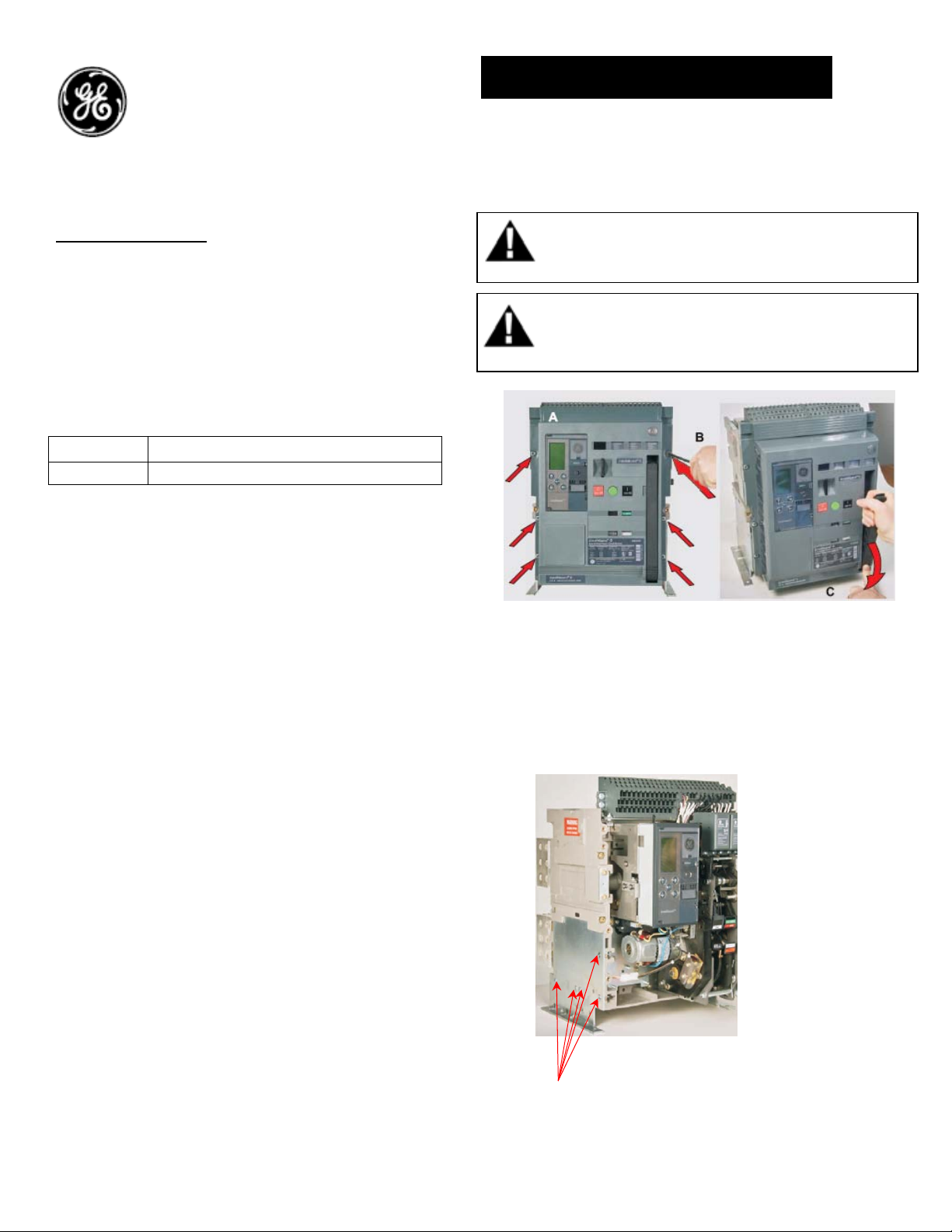
2. Loosen the 6 screws on front cover (fascia)
using a pozidrive screw driver as shown in Fig 1.B
Rotate the charging handle down and slide the
front cover over the handle to remove the front
cover as shown in Fig. 1.
DEH-41383 Installation Instructions
EntelliGuard ® G Circuit Breaker
Accessories
Wall mounting Kit
Figure 1. (A) Front Cover (B) Screw Removal (C) Handle
Rotation
3. Remove the mounting plate which is
assembled to the breaker by removing the fixing
screws as shown in Fig. 2.
Figure 2.
WARNING: Before installing any accessories, turn the
breaker OFF, disconnect it from all voltage sources,
and discharge the closing spings.
AVERTISSEMENT: Avant d’installer tout accessoire,
mettre le disjoncteur en position OFF, le déconnecter
de toute tension d’alimentation , et décharger les
resorts d’armement
Fixing screws
1
Page 2
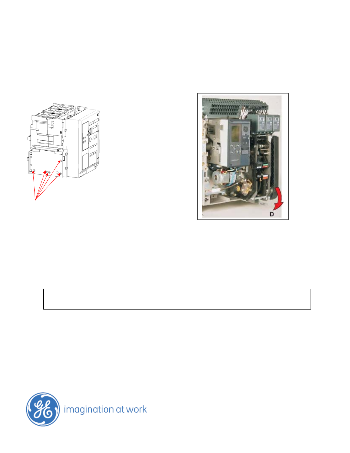
4. Assemble the LH and RH mounting plate using
the screws removed from the Breaker as shown
in fig. 3.
Assemble fixing screws
Figure 3
5. To reinstall the cover, rotate the charging
handle down and slide the front cover over the
handle to assemble the front cover to housing as
shown in Fig. 4
These instructions do not purport to cover all details or variations in equipment nor, to provide contingency to be met in connection
with installation, operation, or maintenance. Should further information be desired, or should particular problems arise which are not
covered sufficiently for the purchaser’s purposes, the matter should be referred to GE.
GE
41 Woodford Ave, Plainville, CT 06062
www.geelectrical.com
© 2009 General Electric Company
6. Ensure the fascia is aligned properly with the
trip unit and the pad lock features of the breaker
7. Fasten the 6 mounting screws of fascia with
the housing using a pozidrive screwdriver as
shown in Fig. 4. Apply torque of 6 Nm (4.42 ft-lbs).
Figure 4
-
2
 Loading...