

Page 1

Introduction
Undervoltage Release:
A device designed to open the breaker contacts
and to prevent the breaker from closing when in
a ‘No volt’ condition. On a de-energization the
Undervoltage release activates the circuit breaker
mechanism and ensures a rapid disconnection of
the main contacts and the device prevents the
Power Circuit Breaker from closing. The
EntelliGuard G™ Undervoltage release is
designed to react within a pre-defined Voltage
band, only reacting when the voltage supply
drops below the limits of this band. To prevent
nuisance tripping due to short power
interruptions or ‘Brown Outs’ the device has a
built in delay of 50 Milliseconds when Voltage is at
or below 50% of rated Voltage. Two under
voltage Releases can be mounted in each Power
Circuit Breaker.
Table 1.
Catalog No DC Voltage AC Voltage
GUVT024DR 24V
GUVT030DR 30V
GUVT048R 48V 48V
GUVT060DR 60-72V
GUVT120R 110-130V 120-130V
GUVT208AR 208V
GUVT240R 220-240V 220-240V
GUVT277R 250V 250-277V
DEH-41410 Installation Instructions
EntelliGuard ® G Circuit Breaker
Accessories
Undervoltage Release
WARNING: Before installing any accessories, turn the
breaker OFF, disconnect it from all voltage sources,
and discharge the closing spings.
AVERTISSEMENT: Avant d’installer tout accessoire,
mettre le disjoncteur en position OFF, le déconnecter
de toute tension d’alimentation , et décharger les
resorts d’armement
For an External Time Delay Module (1-3 second
delay) refer to Pub DEH-41406
Inrush Power: 350VA
Steady state : 40VA
Use the following procedure to install the
Undervoltage Device accessory into the circuit
breaker.
1. Verify that the rating on the Undervoltage
Device identification plate matches the voltage
rating required for the application, as listed in
Table 1.
2. Turn the breaker off and discharge the closing
springs by depressing the OFF and ON buttons in
the sequence OFF-ON-OFF. Verify that the
breaker OFF-ON indicator shows OFF on a green
background and that the charge indicator shows
DISCHARGE on a white background. If installing
in a draw-out type breaker remove breaker from
adaptor (cassette) before continuing.
3. Loosen the 6 screws on front cover (fascia)
using a posidrive screw driver as shown in Fig 1.B
Rotate the charging handle down and slide the
front cover over the handle to remove the front
cover as shown in Fig. 1.C.
1
Page 2
hooks into the mechanism top support plate as
shown in the Fig. 3.
Figure 1. (A) Front Cover (B) Screw Removal (C) Handle
Rotation
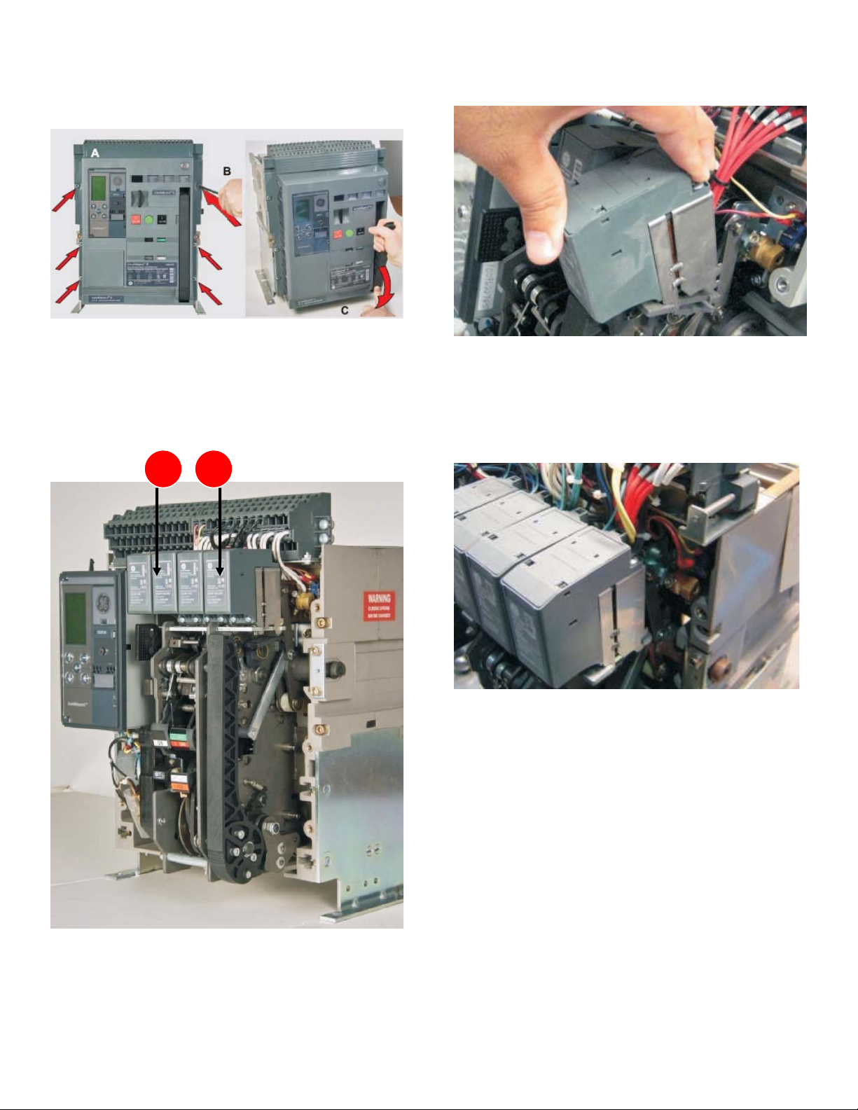
4. This accessory is mounted on the mechanism.
nd
Top plate at 2
or 4th location as shown in Fig. 2.
Figure 3. Insert top plate
6. Tilt the device backwards until the rear hooks
engage in the slots on the mechanism top
support plate as shown in the Fig. 4
Figure 4. Snap on.
7. After installing the UV on the mechanism top
plate, connect the input wire assembly plug to the
nd
A7/A8 if installed (2
location) or A12/A13 (4th
location) marked on the secondary disconnect as
shown in Fig. 5.
Figure 2.
5. Tilt the coil forward and engage the front
2
Page 3

Figure 5. Wire assembly
8. Ensure that the plug in connection is firm and
that the plug is inserted into the correct terminals.
9. To reinstall the cover, rotate the charging
handle down and slide the front cover over the
handle to assemble the front cover to housing as
shown in Fig. 6.
Figure 6.
10. Ensure the fascia is aligned properly with the
trip unit and the pad lock features of the breaker.
11. Fasten the 6 mounting screws of fascia with
the housing using a pozidrive screwdriver. Apply
torque of 6 Nm (4.42 ft-lbs).
3
Page 4

Reference:
Undervoltage Device Connection Scheme:
These instructions do not purport to cover all details or variations in equipment nor, to provide contingency to be met in connection
with installation, operation, or maintenance. Should further information be desired, or should particular problems arise which are not
covered sufficiently for the purchaser’s purposes, the matter should be referred to GE.
GE
41 Woodford Ave, Plainville, CT 06062
www.geelectrical.com
© 2009 General Electric Company
-
4
 Loading...