

Page 1
Introduction
Ready To Close (RTC):
Ready to close switch indicates the breaker
readiness status. It indicates when the following
conditions are met.
- The circuit breaker is open
- The closing springs are charged
- The circuit breaker in not locked/
interlocked in open position
- There is no standing closing order
- There is no standing opening order
The indication can be known either through the
trip unit or remotely. RTC thru trip unit is signal
rated contact. RTC thru secondary disconnect
can be power rated or signal rated. When RTC
signal is used thru the secondary disconnect, it
replaces the spring charge status contact.
DEH-41419 Installation Instructions
EntelliGuard ® G Circuit Breaker
Accessories
Ready To Close (RTC)
WARNING: Before installing any accessories, turn the
breaker OFF, disconnect it from all voltage sources,
and discharge the closing spings.
AVERTISSEMENT: Avant d’installer tout accessoire,
mettre le disjoncteur en position OFF, le déconnecter
de toute tension d’alimentation , et décharger les
resorts d’armement
RTC TO SD, Power Rated Contact:
Cat No
AC Ratings
125Vac 6A
250Vac 6A
GRTC1
RTC TO Trip Unit, Signal rated Contact
Cat No
Table 1.Catalog Numbers and Ratings:
RTC TO SD, Signal rated Contact:
Cat No
AC Ratings 125Vac 0.1A
DC Ratings 30Vdc 0.1A
GRTC2
AC Ratings 125Vac 0.1A
DC Ratings 30Vdc 0.1A
GRTC3
Use the following procedure to install the Ready
To Close (RTC) accessory into the circuit breaker.
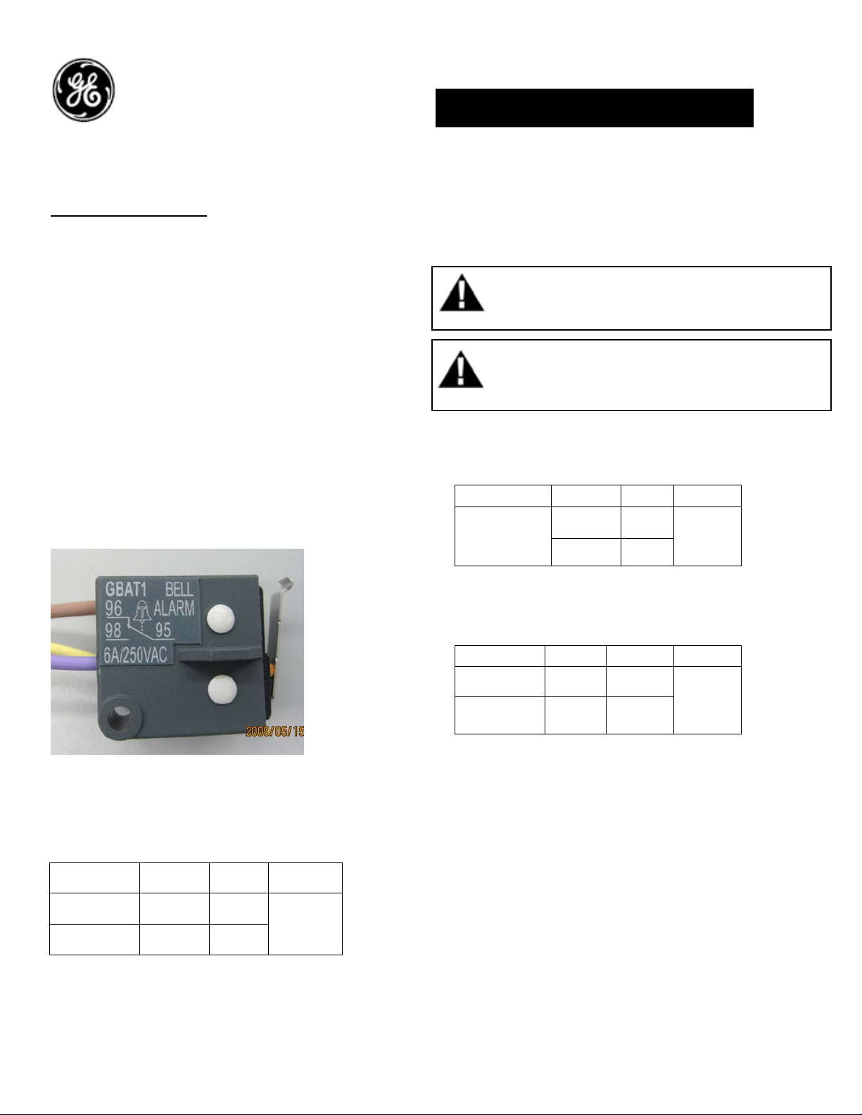
1. Verify that the rating on the Ready To Close
(RTC) identification plate matches the voltage
rating required for the application, as listed in
Table 1.
2. Turn the breaker off and discharge the closing
springs by depressing the OFF and ON buttons in
the sequence OFF-ON-OFF. Verify that the
breaker OFF-ON indicator shows OFF on a green
background and that the charge indicator shows
1
Page 2
DISCHARGE on a white background. If installing
in a draw-out type breaker remove breaker from
adaptor (cassette) before continuing.
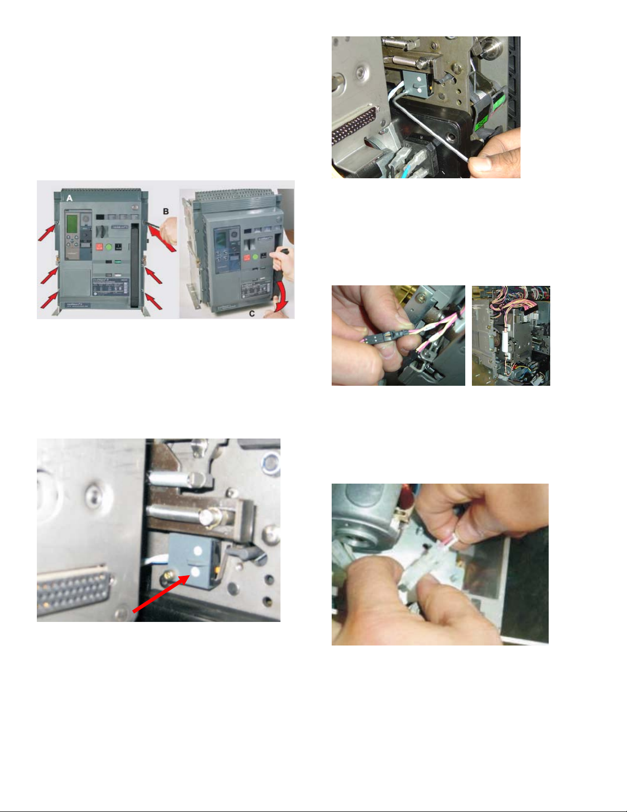
3. Loosen the 6 screws on front cover (fascia)
using a posidrive screw driver as shown in Fig 1.B
Rotate the charging handle down and slide the
front cover over the handle to remove the front
cover as shown in Fig. 1.C.
Figure 3. Screw assembly
6. When RTC thru trip unit is used, plug the
connector from the RTC switch assembly to the
connector marked as RTC from the harness of the
trip unit as shown in Fig. 4.
Figure 1. (A) Front Cover (B) Screw Removal (C) Handle
Rotation
4. Slide the RTC switch assembly over the
mechanism side sheet and locate in the two
locating holes as shown in fig 2.
Figure 4. Connector Plug Assembly
7. If RTC is used thru the secondary disconnect,
then first unplug the spring charge contact
connector from motor as shown in Fig. 5
Figure 2. Assembly on mechanism
5. Assemble the screw with washer as shown in
Fig. 3 Tighten the screw to torque 1.2Nm (0.9 ftlbs).
Figure 5. Unplug Spring Contact
7. Plug the connector from the RTC switch
assembly with the plug marked as RTC as shown
in fig 6.
2
Page 3

Figure 6. Connector Plug Assembly
8. To reinstall the cover, rotate the charging
handle down and slide the front cover over the
handle to assemble the front cover to housing as
shown in Fig. 7.
Figure 7.
9. Ensure the fascia is aligned properly with the
trip unit and the pad lock features of the breaker.
10. Fasten the 6 mounting screws of fascia with
the housing using a pozidrive screwdriver. Apply
torque of 6 Nm (4.42ft-lbs).
3
Page 4

Reference:
Ready To Close (RTC) Connection Scheme:
These instructions do not purport to cover all details or variations in equipment nor, to provide contingency to be met in connection
with installation, operation, or maintenance. Should further information be desired, or should particular problems arise which are not
covered sufficiently for the purchaser’s purposes, the matter should be referred to GE.
GE
41 Woodford Ave, Plainville, CT 06062
www.geelectrical.com
© 2009 General Electric Company
-
4
 Loading...