

Page 1
EntelliGuard-G
DEH-41387
Instruction sheet
Gebrauchsanleitung
Instrukcja arkuza
-NEUTRAL SENSOR (ROGOWSKI COIL)
-NEUTRALWANDLER (ROGOWSKI SPULE)
DEH-41387 R02 R1213642 8/30/13
Page 2
Instruction sheet
EntelliGuard-G
Gebrauchsanleitung
4.4.9 Neutral Rogowski Coil:
. When an EntelliGuard device in a 3 pole
configuration is used in a 4 wire network a
fourth sensor needs to be placed in the
Neutral. It also must be connected to the Trip
Unit input as indicated elsewhere in the User
Manual.
• The external neutral rogowski mounting kit
comes with three mounting brackets, two fixing
screws, two cable ties, one 2m long twisted pair
extension lead and one neutral rogowski coil
• The mounting bracket has been designed so to
fit a multiple number of standard neutral bar
arrangement as illustrated on figures A, B and C
• As standard frame 1 breakers are provided with
frame 1 external neutral rogowski coils. Likewise
fame 2 breakers are provided with frame 2
external rogowski coils and frame 3 breakers
with the frame 3 Rogowski coils.
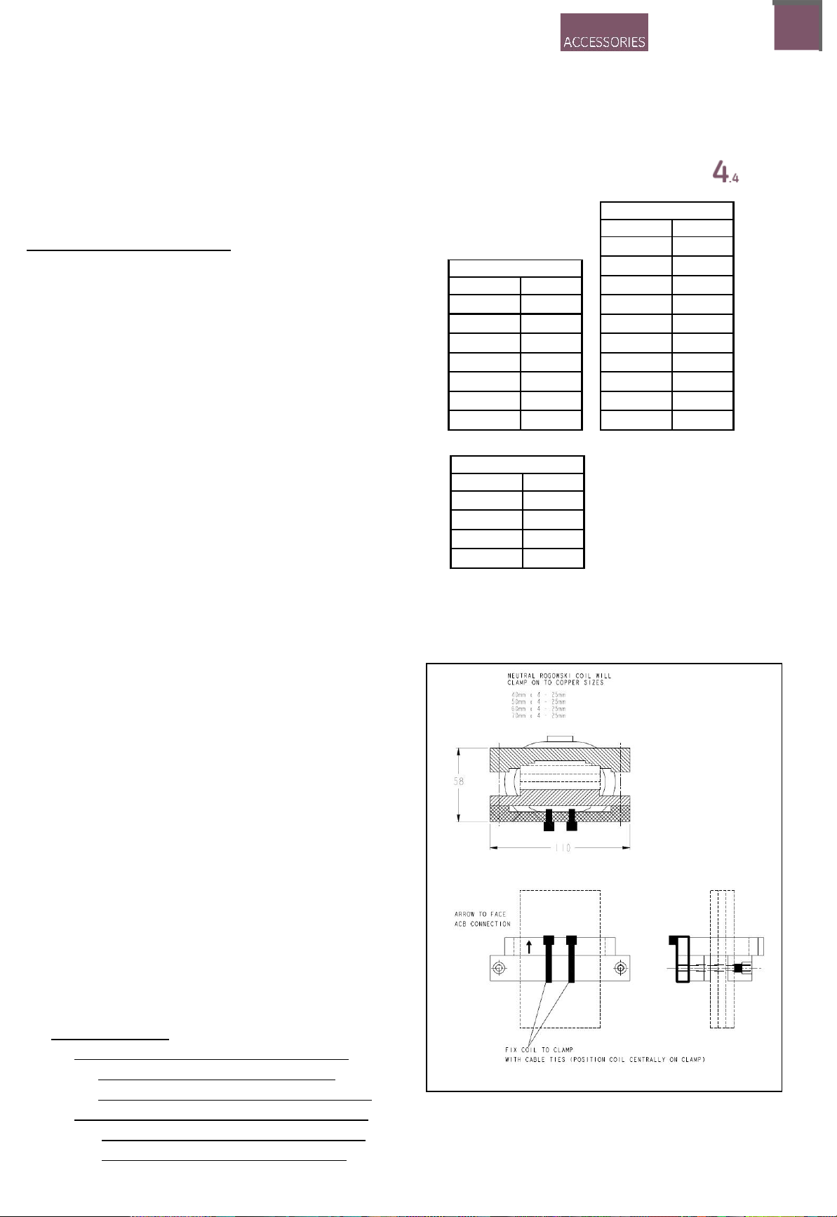
Envelope 1
Cat No Rating
G04HNRC 400A
G07HNRC 630A
G08HNRC 800A
G10HNRC 1000A
G13HNRC 1250A
G16HNRC 1600A
G20HNRC 2000A
Envelope 3
Cat No Rating
G32LNRC 3200A
G40LNRC 4000A
G50LNRC 5000A
G64LNRC 6400A
Fig A: Frame 1 Rogowski
Instrukcja arkuza
Envelope 2
Cat No Rating
G04MNRC 400A
G07MNRC 630A
G08MNRC 800A
G10MNRC 1000A
G13MNRC 1250A
G16MNRC 1600A
G20MNRC 2000A
G25MNRC 2500A
G32MNRC 3200A
G40MNRC 4000A
The neutral rogowski coil should be fitted in the
•
correct location with respect to the neutral earth
connection (restri
For further details consult application notes and
drawings provided.
• The neutral rogowski coil should be positioned
with the arrow facing the main bus bars as
illustrated on figure A, B & C and shown
diagrammatically on figures D and E.
• The 2m extension lead should next be plugged
into the neutral rogowski coil flying lead and
routed back to the breaker. The end connectors
marked +ve and -ve should be terminated at the
secondary disconnect in-line with connections
shown on figure D and E. Using a longer
extension lead than that provided may result in
EMI affecting the performance of the trip unit
•
Important Note:
a. If no neutral sensor is in use, then a
shorting jumper must be installed
between the NRC+ and NRC- terminals
b. If a neutral sensor is in use, it must be
wired to these two terminals, and the
shorting jumper must be removed.
cted or unrestricted neutral).
4.4.9-01
Page 3

EntelliGuard-G
EntelliGuard-G
EntelliGuard-G
Instruction sheet
Gebrauchsanleitung
Fig B: Frame 2 Rogowski
Fig C: Frame 3 Rogowski
4.4.9-02
Page 4

EntelliGuard-G
Instruction sheet
Figure D.
Diagram illustrating neutral rogowski coil fixing position
and directions for applications where busbars connected
to top terminals and cables connected to bottom terminal
of ACB.
Gebrauchsanleitung
Figure E.
Diagram illustrating neutral rogowski coil fixing position
and direction for applications where bus bars connected
to bottom terminals and cables connected to top
terminals of ACB.
Arro w mark on rog owski
points in this direction
Restricted Neutral
Position
Unrestricted
Neutral Position
Restricted Ne utral
Position
Arro w mark on rogowsk i
points in this direction
Termination at Secondary
disconnect terminals
+ve to A37 & -ve to A36
Termination at Secondary
disconnect terminals
+ve to A37 & -ve to A36
Unrestricted
Neutral Position
4.4.9-03
 Loading...