

Page 1
Introduction
NETWORK INTERLOCK DEVICE (NI)
The Network Interlock Device locks the breaker In
OFF position electrically and mechanically.
When this device receives a pulse all local
breaker functionality is disabled except the
tripping of the device on any over current fault.
On the receipt of a 2nd pulse normal operation is
re-instated. The presence of mains power does
not affect the locking and/or re-instatement of
this device. Each device has a local RESET button
that only can be accessed after breaker cover
removal.
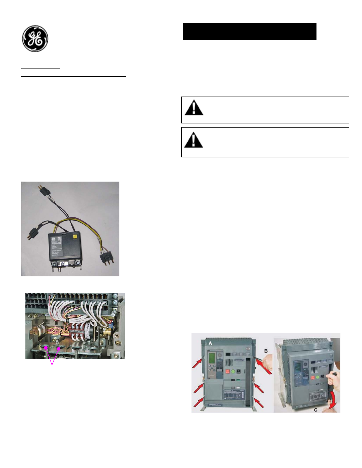
Figure 1
NI mounting location
Figure 2
DEH-41461 Installation Instructions
EntelliGuard ® G Circuit Breaker
Accessories
NETWORK INTERLOCK DEVICE (NI)
WARNING: Before installing any accessories, turn the
breaker OFF, disconnect it from all voltage sources,
and discharge the closing spings.
AVERTISSEMENT: Avant d’installer tout accessoire,
mettre le disjoncteur en position OFF, le déconnecter
de toute tension d’alimentation , et décharger les
resorts d’armement
Use the following procedure to install the
Network Interlock accessory into the circuit
breaker.
1. Turn the breaker off and discharge the closing
springs by depressing the OFF and ON buttons
in the sequence OFF-ON-OFF. Verify that the
breaker OFF-ON indicator shows OFF on a
green background and that the charge
indicator shows DISCHARGE on a white
background. If installing in a draw-out type
breaker remove breaker from adaptor
(cassette) before continuing.
2. Loosen the 6 screws on front cover (fascia)
using a pozidrive screw driver as shown in Fig
3.B
3. Rotate the charging handle down and slide the
front cover over the handle to remove the
front cover as shown in Fig. 3.C
Figure 3
1
Page 2
4. Network interlock uses two locations of
the coils on the mechanism top plate at 1st
& 2nd locations as shown in Fig. 2
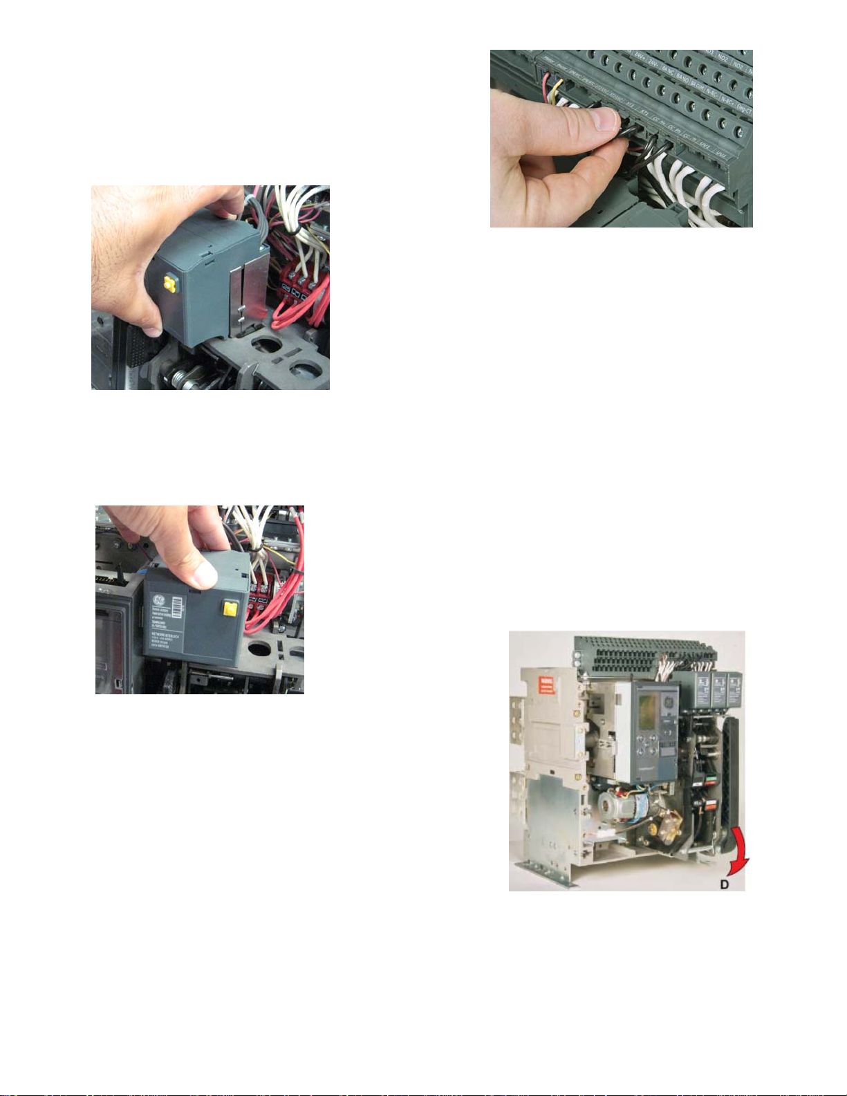
5. Tilt the NI forward and engage the front
hooks into the mechanism top support
plate as shown in the Fig. 4
Figure 4
6. Tilt the device backwards until the rear
hooks engage in the slots on the
mechanism top support plate as shown in
the Fig. 5
Figure 6
8. Connect the NI status switch wire
assembly plugs to the B4-B5-B6 locations
on the block B
9. Ensure that the plug in connection is firm
and that the plug is inserted into the
correct terminals.
10. To reinstall the cover, rotate the charging
handle down and slide the front cover
over the handle to assemble the front
cover to housing as shown in Fig. 7
11. Ensure the fascia is aligned properly with
the trip unit and the pad lock features of
the breaker.
12. Fasten the 6 mounting screws of fascia
with the housing using a pozidrive
screwdriver. Apply torque of 6 Nm (4.42 ftlbs)
Figure 5
7. Connect the input wire assembly plugs to
the A5-A6 and A7-A8 locations marked on
the secondary disconnect block A as
shown in Fig. D.
Figure 7
2
Page 3

Connection Scheme:
These instructions do not purport to cover all details or variations in equipment nor, to provide contingency to be met in connection
with installation, operation, or maintenance. Should further information be desired, or should particular problems arise which are not
covered sufficiently for the purchaser’s purposes, the matter should be referred to GE.
GE
41 Woodford Ave, Plainville, CT 06062
www.geelectrical.com
© 2009 General Electric Company
-
3
 Loading...