

Page 1
Back Connected Terminations
Envelope 2, 3200A ANSI, Fixed type
Terminal assemblies are supplied with the
Entelliguard breaker. Fixed breakers have Back or
Front Connected Terminations available. This
instruction is for Back Connected Terminations
M12 Mtg
M12 Plain
M12 Plain
washer
washer
M12 Spring
M12 Spring
washer
washer
M12 Mtg
Hardware
Hardware
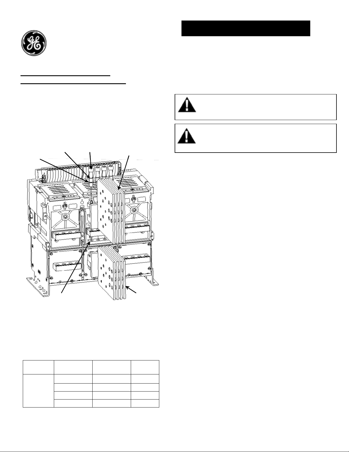
Fig A. Back Connected Terminations assembly, (Middle pole)
For 3200 Amperes (ANSI) 3 pole, fixed type
Table 1. Back Connected Terminations
Envelope
Size
Envelope 2
Nut plate
Nut plate
Catalog numbers
Catalog # Description TYPE
GBB232TBB3
GBB232BBB3
GBB232TBB4
GBB232BBB3
Top side
Bottom side
Top side
Bottom side
Top terminal
Top terminal
assembly
assembly
Bottom terminal
Bottom termin
assembly
assembly
3 pole
3 pole
4 pole
4 pole
al
DEH- 41443 Installation Instructions
EntelliGuard ® G Circuit Breaker
Accessories
Back Connected Terminations for
Fixed Breaker
WARNING: Before installing any accessories, turn the
breaker OFF, disconnect it from all voltage sources,
and discharge the closing spings.
AVERTISSEMENT: Avant d’installer tout accessoire,
mettre le disjoncteur en position OFF, le déconnecter
de toute tension d’alimentation, et décharger les
resorts d’armement
Back Connected Terminations Assembly (3 Pole)
Procedure:
1. Turn the breaker off and discharge the closing
springs by depressing the OFF and ON buttons in
the sequence OFF-ON-OFF. Verify that the
breaker OFF-ON indicator shows OFF on a green
background and that the charge indicator shows
DISCHARGE on a white background.
2. First assemble & orient the middle terminations
assemblies on to the breaker rear terminals as
shown in Fig A.
3. Middle top & bottom terminal assemblies to be
tightened with M12 hardware’s as shown in Fig A,
to 80 Nm (59 ft-lbs) torque.
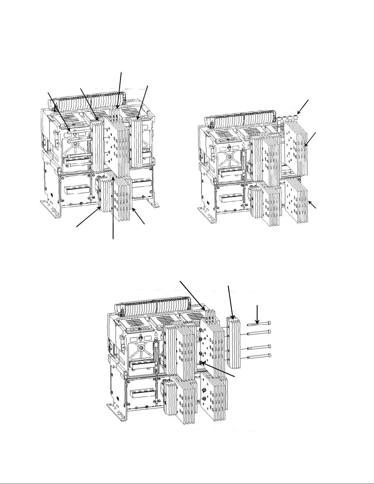
4. Assemble the heat sinks LH & RH with spacers
introduced in between the multiple pads of
terminal assemblies as shown in Fig B for bottom
& top sides. Tightened them with M8 mounting
hardware’s to 16 Nm (11.8 ft-lbs) torque.
5. Assemble the outer terminal assemblies on
bottom and top side with M12 hardware
tightened to 80 Nm (59 ft-lbs) torque as shown in
Fig C.
6. Assemble the heat sinks RH with clearance holes
& spacers introduced in between the multiple
pads of outer terminal assemblies as shown in fig
D, for bottom & top sides and tightened them
with M8 mounting hardware’s to 16 Nm (11.8 ftlbs) torque.
1
Page 2
7. Assemble remaining terminal assemblies similarly
on all poles so as to populate as 3pole / 4 pole
breaker.
M8, Mtg
M8, Mtg
hardware
hardware
Top Heat sink LH
Top Heat sink LH
(with clearance hole)
(with clearance hole)
Top Spacer
Top Spacer
Top Heat sink RH
Top Heat sink RH
(with tapping)
(with tapping)
Bottom Heat sink LH
Bottom Heat sink LH
(with clearance hole)
(with clearance hole)
Bottom Spacer
Bottom Spacer
Bottom Heat sink RH
Bottom Heat sink RH
(with tapping)
(with tapping)
Fig B. Heat sink Asm with spacers (Middle pole)
For 3200A , (ANSI) 3 pole, fixed type
Top Spacer
Top Spacer
Fig D. Outer pole Heat Sink with spacer assembly
For 3200 Amperes (ANSI), 3 Pole, Fixed type
8. The bus bars to be supported within 200mm
distance and tightened to 80Nm (59 ft-lbs) torque.
M12 Mtg
M12 Mtg
hardwares
hardwares
Top terminal
Top terminal
assembly
assembly
Bottom terminal
Bottom terminal
assembly
assembly
Fig C. Outer pole, Back Connected Terminations
asm For 3200 A, (ANSI) 3 Pole, fixed type
Top Heat sink (RH)
Top Heat sink (RH)
(with clearance hole)
(with clearance hole)
M8, Mtg
M8, Mtg
hardware
hardware
M8, Nuts
M8, Nuts
2
Page 3

** For 3 Pole , L2 Phase to have two heat sinks,
While outer poles L1 & L3 to have only one outer
heat sinks assembled
L1
L1
L2
L2
L3
L3
Fig E. Envelope 2, 3200A ANSI 3 Pole, fixed type, Top view
Fig G. Envelope 2, 3200A ANSI 3 Pole, fixed type
Fig F. Envelope 2 , 3200A ANSI 3 Pole, fixed type, Side
view
3
Page 4

Back Connected Terminations Assembly (4 Pole)
Procedure:
1. Similar Procedure to be followed for 4 pole
breaker with neutral on right or left.
2. For 4 Pole breaker, assemble the L2 pole with
two heat sinks first. Then assemble the
adjacent poles with only one outer heat sinks.
Refer Fig H – Fig L.
N
N
Fig H. Envelope 2, 3200A ANSI 4 Pole, Neutral Left, Top view
Fig I. Envelope 2, 3200A ANSI 4 Pole, Neutral left, fixed
type
L1
L1
L2 L3
L2 L3
L2
L3
L3
Fig J. Envelope 2 , 3200A ANSI 4 Pole ,Neutral Right, Top
view
Fig K. Envelope 2, 3200A ANSI 4 Pole, Neutral Right, fixed
type
Fig L . Envelope 2, 3200A 4 Pole, fixed type, Side
view
L2
L1 N
L1 N
4
Page 5

These instructions do not purport to cover all details or variations in equipment nor, to provide contingency to be met in connection
with installation, operation, or maintenance. Should further information be desired, or should particular problems arise which are not
covered sufficiently for the purchaser’s purposes, the matter should be referred to GE.
GE
41 Woodford Ave, Plainville, CT 06062
www.geelectrical.com
© 2009 General Electric Company
-
5
 Loading...