

Page 1
GE
Data Sheet
EHHD015A0A Hammerhead™ Series; DC-DC Converter Power Modules
18-75Vdc Input; 5Vdc, 15.0A, 75W Output
Features
Compliant to RoHS II EU “Directive 2011/65/EU (-Z versions)
Compliant to REACH Directive (EC) No 1907/2006
Flat and high efficiency curve
Industry standard, DOSA compliant footprint
57.9mm x 22.8mm x 7.6mm
(2.28 in x 0.9 in x 0.30 in)
Low profile height and reduced component skyline
Ultra wide input voltage range: 18-75 V
dc
Tightly regulated output
Remote sense
RoHS Compliant
Output Voltage adjust: 80% to 110% of V
O,nom
Constant switching frequency
Applications
Distributed Power Architectures
Wireless Networks
Access and Optical Network Equipment
Industrial Equipment
Positive remote On/Off logic
Input under/over voltage protection
Output overcurrent and overvoltage protection
Overtemperature protection
No reverse current during output shutdown
Wide operating temperature range (-40°C to 85°C)
Suitable for cold wall cooling using suitable Gap Pad applied
directly to top side of module
ANSI/UL*60950-1-2011 and CAN/CSA† C22.2 No. 60950-1-
Options
Negative Remote On/Off logic (preferred)
Over current/Over temperature/Over voltage protections
(Auto-restart) (preferred)
Heat plate versions (-H)
Surface Mount version (-S)
07, Second Edition + A1:2011 (MOD), dated March 19, 2011;
and DIN EN 60950-1 (VDE‡ 0805 Teil 1):2011-01; EN 609501:2006 + A11:2009 + A1:2010, DIN EN 60950-1/A12 (VDE
0805-1/A12):2011-08; EN 60950-1/A12:2011-02, IEC 609501(ed.2);am1:2009
§
CE mark meets 2006/95/EC directive
Meets the voltage and current requirements for ETSI 300-
132-2 and complies with and licensed for Basic insulation
rating per EN60950-1
2250 Vdc Isolation tested in compliance with IEEE 802.3
standards
**
ISO
9001 and ISO 14001 certified manufacturing facilities
Description
The EHHD015A0A [Hammerhead™] Series, eighth-brick, low-height power modules are isolated dc-dc converters
which provide a single, precisely regulated output voltage over an ultra wide input voltage range of 18-75V
EHHD015A0A provides 5V
nominal output voltage rated for 15Adc output current. The module incorporates GE’s vast heritage for
dc
reliability and quality, while also using the latest in technology, and component and process standardization to achieve highly
competitive cost. The open frame module construction, available in both surface-mount and through-hole packaging, enable
designers to develop cost and space efficient solutions. The module achieves typical full load efficiency greater than 90% at
=24Vdc and VIN=48Vdc. Standard features include remote On/Off, remote sense, output voltage adjustment, overvoltage,
V
IN
overcurrent and overtemperature protection. An optional heat plate allows for external standard, eighth-brick heat sink
attachment to achieve higher output current in high temperature applications.
* UL is a registered trademark of Underwriters Laboratories, Inc.
†
CSA is a registered trademark of Canadian Standards Association.
‡
VDE is a trademark of Verband Deutscher Elektrotechniker e.V.
§
This product is intended for integration into end-user equipment . All of the required procedures of end-use equipment should be followed.
¤ IEEE and 802 are registered trademarks of the Institute of Electrical and Electronics Engineers, Incorporated.
** ISO is a registered trademark of the International Organization of Standards
. The
dc
¤
PoE
April 4, 2013 ©2012 General Electric Company. All rights reserved. Page 1
Page 2
GE
Data Sheet
EHHD015A0A Hammerhead™
Series; DC-DC Converter Power Modules
18-75Vdc Input; 5Vdc, 15.0A, 75W Output
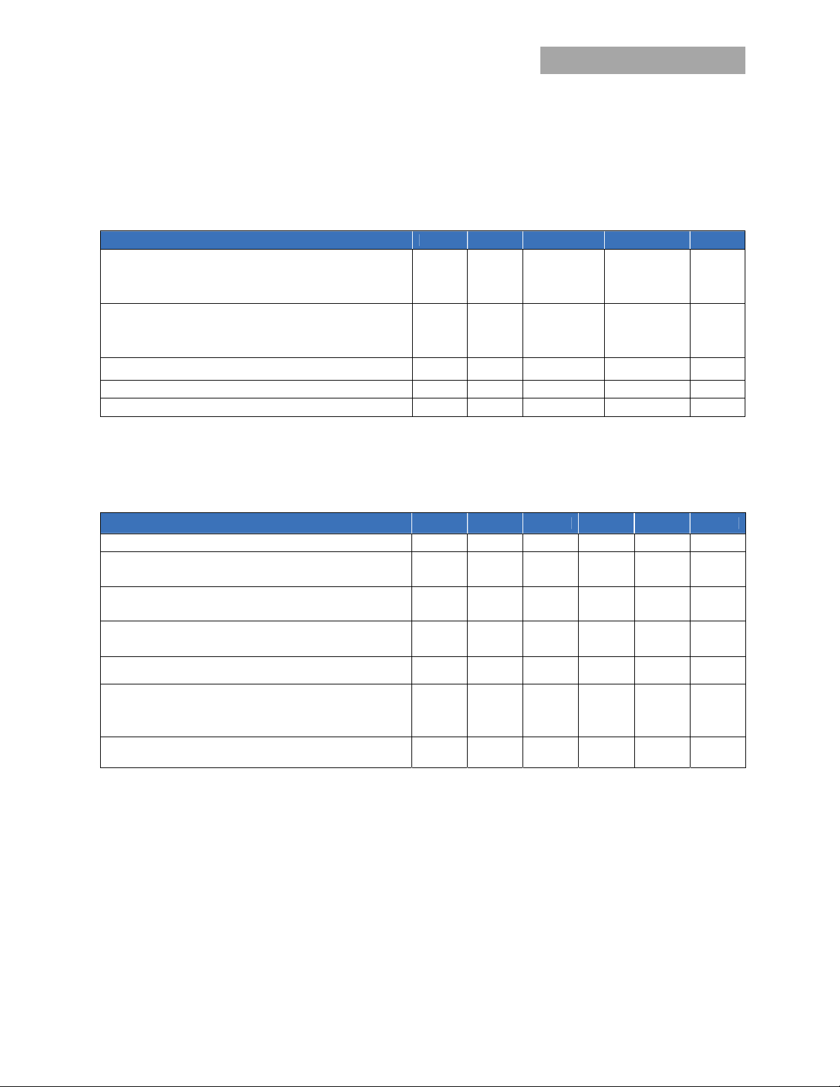
Absolute Maximum Ratings
Stresses in excess of the absolute maximum ratings can cause permanent damage to the device. These are absolute stress ratings
only, functional operation of the device is not implied at these or any other conditions in excess of those given in the operations
sections of the data sheet. Exposure to absolute maximum ratings for extended periods can adversely affect the device reliability.
Parameter Device Symbol Min Max Unit
Input Voltage
Continuous All V
Transient, operational (≤100 ms) All V
Operating Ambient Temperature All T
Maximum Heat Plate Operating Temperature -18H, H T
(see Thermal Considerations section)
Storage Temperature All T
Altitude* All
I/O Isolation voltage (100% factory Hi-Pot tested) All
IN
IN,trans
A
C
stg
-0.3 80 Vdc
-0.3 100 Vdc
-40 85 °C
-40 105 °C
-55 125 °C
4000 m
2250 Vdc
* For higher altitude applications, contact your GE Sales Representative for alternative conditions of use.
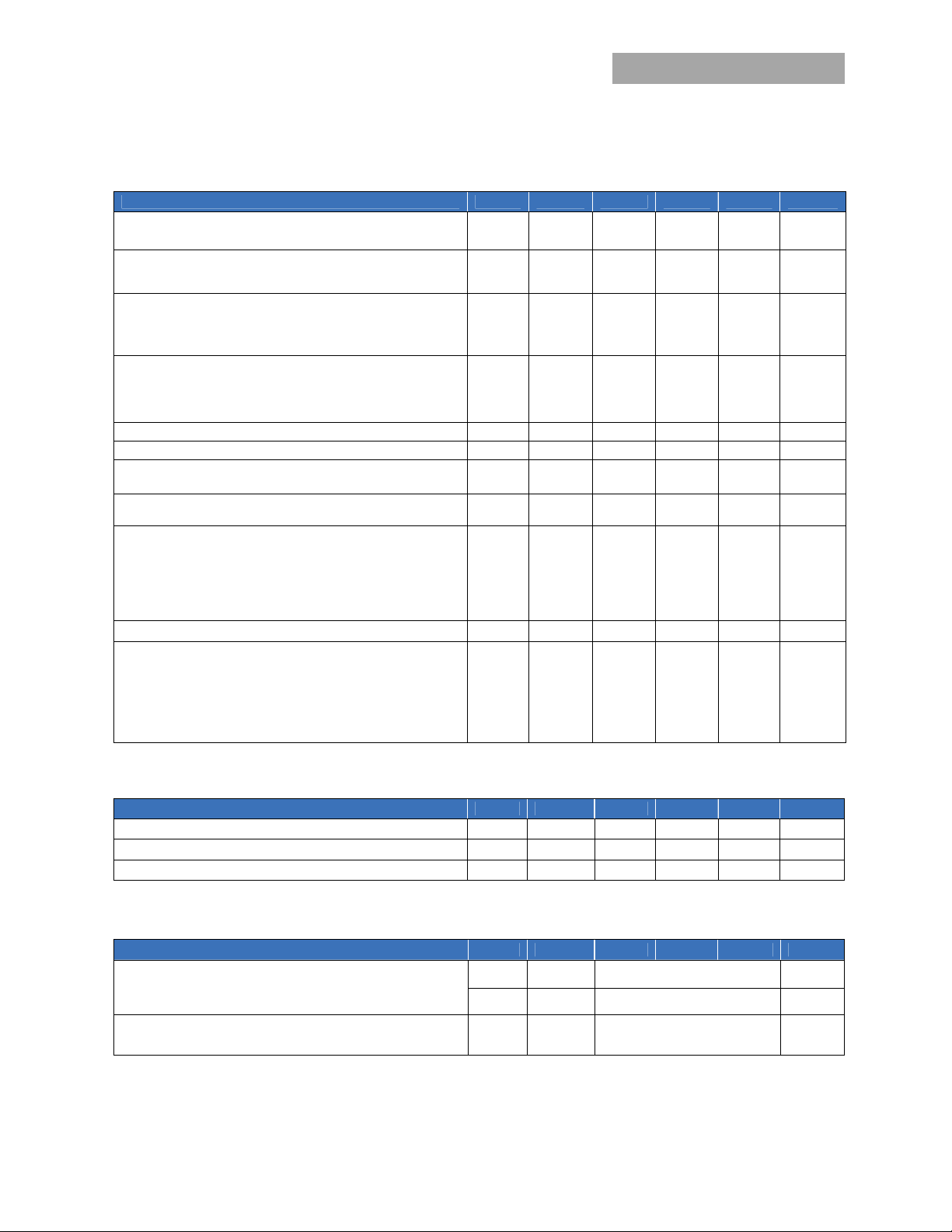
Electrical Specifications
Unless otherwise indicated, specifications apply over all operating input voltage, resistive load, and temperature conditions.
Parameter Device Symbol Min Typ Max Unit
Operating Input Voltage All VIN 18 24/48 75 Vdc
Maximum Input Current
(VIN= V
Input No Load Current
(VIN = 48V, IO = 0, module enabled)
Input Stand-by Current All
(VIN = 48V, module disabled)
Inrush Transient All I2t 0.5 A2s
IN, min
to V
IN, max
, VO= V
O, set
, IO=I
O, max
)
All I
All I
IN,No load
I
IN,stand-by
IN
4.4 5.0 Adc
70 mA
5 8 mA
Input Reflected Ripple Current, peak-to-peak
(5Hz to 20MHz, 1μH source impedance; V
Test configuration section)
Input Ripple Rejection (120Hz) All 50 dB
IN, min
to V
IN, max, IO
= I
Omax
; See
All 30 mA
p-p
CAUTION: This power module is not internally fused. An input line fuse must always be used.
This power module can be used in a wide variety of applications, ranging from simple standalone operation to an integrated part
of sophisticated power architectures. To preserve maximum flexibility, internal fusing is not included, however, to achieve
maximum safety and system protection, always use an input line fuse. The safety agencies require a fast-acting fuse with a
maximum rating of 10 A (see Safety Considerations section). Based on the information provided in this data sheet on inrush energy
and maximum dc input current, the same type of fuse with a lower rating can be used. Refer to the fuse manufacturer’s data sheet
for further information.
April 4, 2013 ©2012 General Electric Company. All rights reserved. Page 2
Page 3
GE
Data Sheet
EHHD015A0A Hammerhead™
Series; DC-DC Converter Power Modules
18-75Vdc Input; 5Vdc, 15.0A, 75W Output
Electrical Specifications (continued)
Parameter Device Symbol Min Typ Max Unit
Nominal Output Voltage Set-point
VIN= 24V to 48V IO=I
O, max
, TA=25°C)
All V
O, set
Output Voltage
(Over all operating input voltage, resistive load, and temperature
All V
O
conditions until end of life)
Output Regulation
Line (VIN=V
Load (IO=I
Temperature (T
IN, min
O, min
to V
to I
O, max
ref=TA, min
) All
IN, max
)
to T
) All
A, max
All
Output Ripple and Noise
(VIN=V
IN, min
to V
IN, max
, IO= I
O, max
, TA=T
A, min
to T
)
A, max
RMS (5Hz to 20MHz bandwidth) All
Peak-to-Peak (5Hz to 20MHz bandwidth) All
External Capacitance All C
Output Current All I
Output Current Limit Inception (Hiccup Mode )
(VO= 90% of V
Output Short-Circuit Current
(VO≤250mV) ( Hiccup Mode )
) 5.0
O, set
All I
O, max
O
I
O, lim
O, s/c
Efficiency
VIN=24V, TA=25°C, IO=7.5A, VO = 5.0V All η 90.5 %
VIN=24V, TA=25°C, IO=15A, VO = 5.0V All η 90.5 %
VIN=48V, TA=25°C, IO=7.5A, VO = 5.0V All η 89.0 %
VIN=48V, TA=25°C, IO=15A, VO = 5.0V All η 90.0 %
Switching Frequency All f
sw
Dynamic Load Response
(dIo/dt=0.1A/s; VIN = 24V or 48V; TA=25°C; CO>100μF)
Load Change from Io= 50% to 75% or 25% to 50% of I
o,max
Peak Deviation All V
Settling Time (Vo<10% peak deviation)
All t
pk
s
4.92 5.0 5.08 V
4.85
0
10 20 mV
35 80 mV
5.15 % V
±0.2 % V
±0.2 % V
±1.0
5,000 μF
% V
dc
O, set
O, set
O, set
O, set
rms
pk-pk
0 15 Adc
16 19 24 Adc
5 A
rms
330 kHz
3
200
% V
s
O, set
Isolation Specifications
Parameter Device Symbol Min Typ Max Unit
Isolation Capacitance All C
Isolation Resistance All R
I/O Isolation Voltage (100% factory Hi-pot tested) All All
iso
iso
100
1000
2250 Vdc
pF
MΩ
General Specifications
Parameter Device Symbol Min Typ Max Unit
Calculated Reliability based upon Telcordia SR-332 Issue 2: Method I
Case 3 (I
=80%I
O
, TA=40°C, airflow = 200 lfm, 90% confidence)
O, max
All FIT 339.0
All MTBF 2,949,583 Hours
Weight (Open Frame) All 19 (0.7) g (oz.)
Weight (with Heatplate) All 30 (1.1) g (oz.)
9
10
/Hour
s
April 4, 2013 ©2012 General Electric Company. All rights reserved. Page 3
Page 4
GE
Data Sheet
EHHD015A0A Hammerhead™
Series; DC-DC Converter Power Modules
18-75Vdc Input; 5Vdc, 15.0A, 75W Output
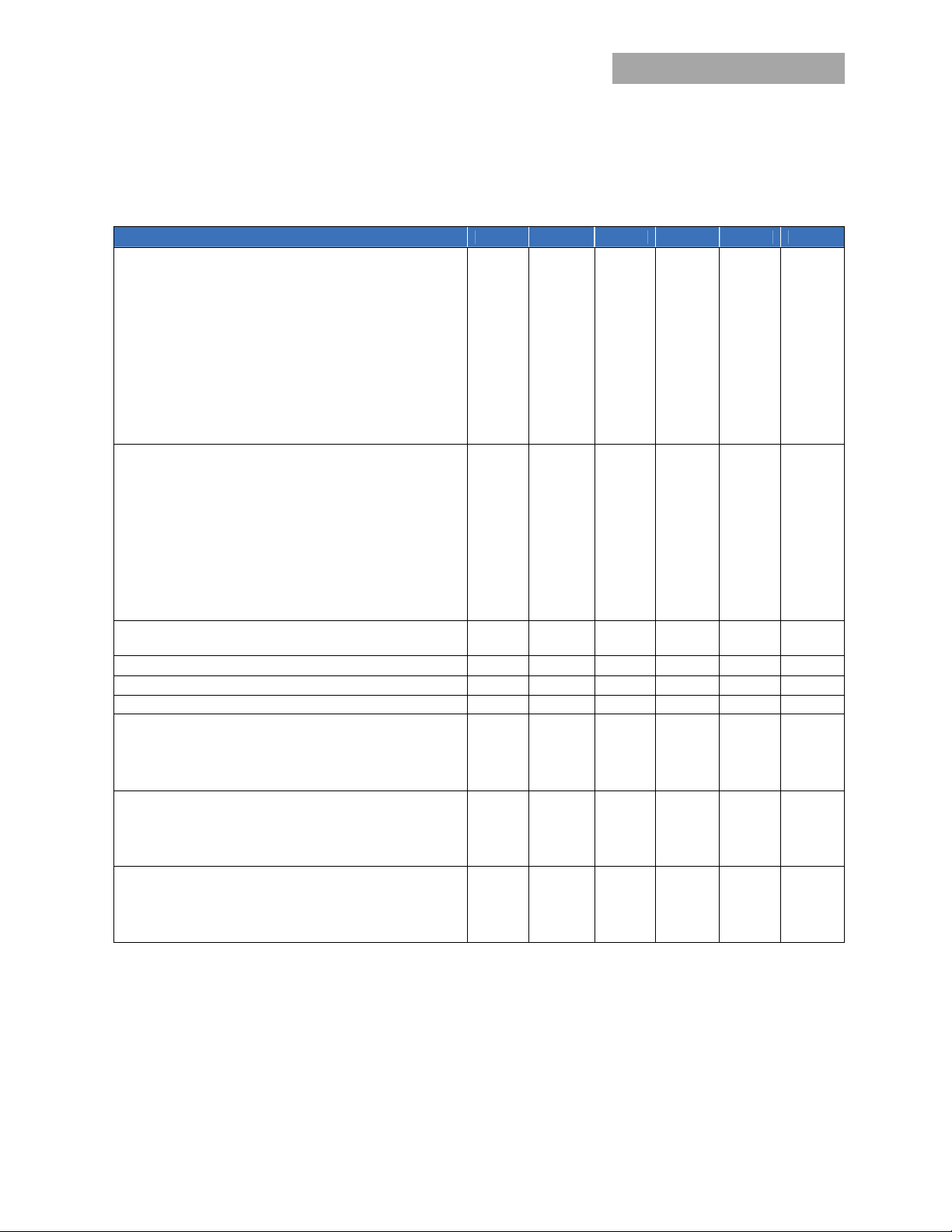
Feature Specifications
Unless otherwise indicated, specifications apply over all operating input voltage, resistive load, and temperature conditions. See
Feature Descriptions for additional information.
Parameter Device Symbol Min Typ Max Unit
Remote On/Off Signal Interface
(VIN=V
Signal referenced to V
Negative Logic: device code suffix “1”
Logic Low = module On, Logic High = module Off
Positive Logic: No device code suffix required
Logic Low = module Off, Logic High = module On
Turn-On Delay and Rise Times
(IO=I
Case 1: Input power is applied for at least 1 second,
Case 2: On/Off input is set to Logic Low (Module
ON) and then input power is applied (T
instant at which V
Output voltage Rise time (time for Vo to rise from 10%
of V
Output voltage overshoot – Startup
IO= I
Remote Sense Range All V
Output Voltage Adjustment Range All 80 110 % V
Output Overvoltage Protection
Overtemperature Protection – Hiccup Auto Restart
Input Undervoltage Lockout All V
to V
IN, min
Logic Low - Remote On/Off Current All I
Logic Low - On/Off Voltage All V
Logic High Voltage – (Typ = Open Collector) All V
Logic High maximum allowable leakage current All I
O, max , VIN=VIN, nom, TA
and then the On/Off input is set from OFF to ON
= on/off pin transition until VO = 10% of V
(T
delay
to 90% of V
o,set
; VIN=V
O, max
Turn-on Threshold
Turn-off Threshold
; open collector or equivalent,
IN, max
terminal)
IN-
on/off
on/off
on/off
on/off
-0.7
0.3 1.0 mA
1.2 Vdc
5 V
10 μA
= 25oC)
— 12 — msec
delay
— — 150 msec
delay
rise
SENSE
O, limit
T
ref
T
ref
UVLO
— 5 12 msec
— 3 % V
10 % V
5.7
6.5 Vdc
135 OC
120 OC
17 18 V
14 15 16 Vdc
IN, min
IN
o, set
to V
)
O, set
from
= V
IN, min
until Vo=10% of V
delay
O,set
)
)
, TA = 25 oC
IN, max
All T
All T
All
All V
Open
frame
Heat
Plate
All T
dc
O, set
O, set
O, set
dc
Hysteresis 1 2 Vdc
Input Overvoltage Lockout All V
Turn-on Threshold 76 79
Turn-off Threshold
Hysteresis 1 2
OVLO
Vdc
Vdc
81 83 Vdc
April 4, 2013 ©2012 General Electric Company. All rights reserved. Page 4
Page 5
GE
t
Data Sheet
EHHD015A0A Hammerhead™
Series; DC-DC Converter Power Modules
18-75Vdc Input; 5Vdc, 15.0A, 75W Output
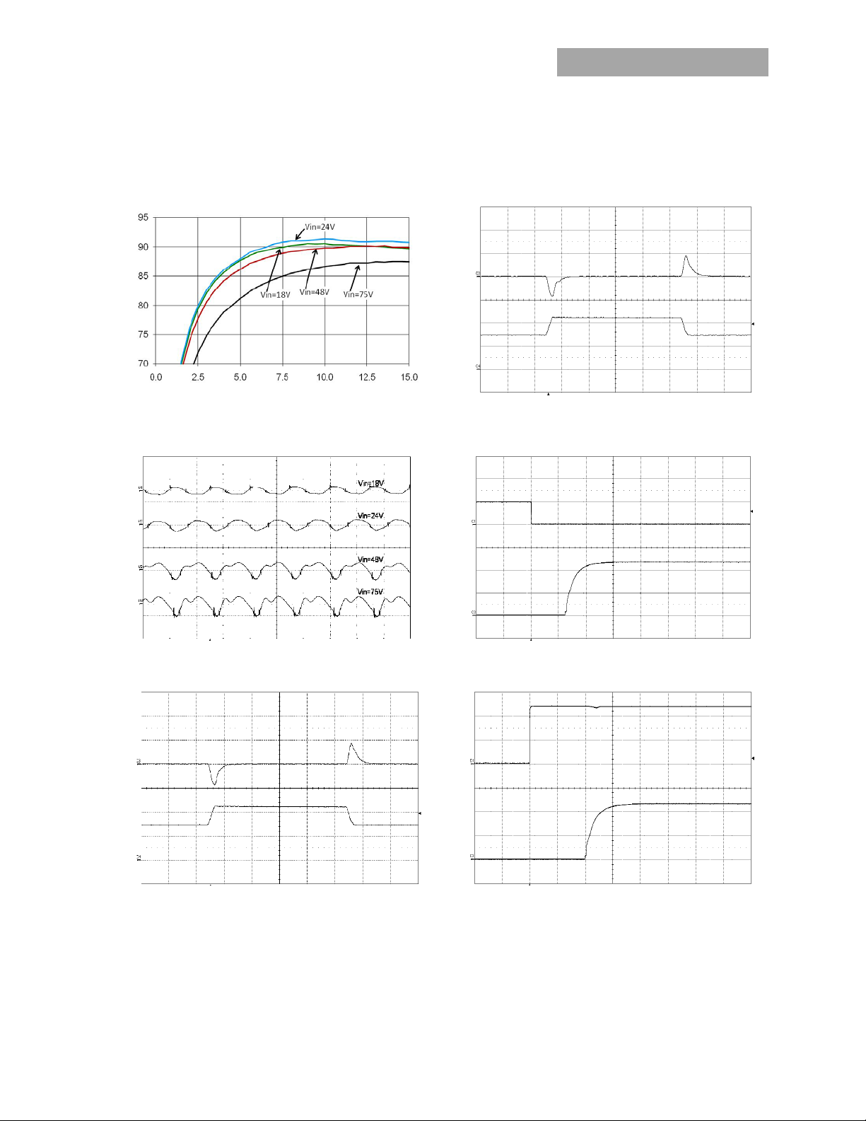
Characteristic Curves
The following figures provide typical characteristics for the EHHD015A0A (5.0V, 15A) at 25 OC. The figures are identical for either
positive or negative remote On/Off logic.
(V) (200mV/div)
O
EFFICIENCY, (%)
OUTPUT CURRENT, IO (A) TIME, t (200µs/div)
Figure 1. Converter Efficiency versus Output Current. Figure 4. Transient Response to 0.1A/µS Dynamic Load Change
Io(A) (5A/div) V
OUTPUT CURRENT OUTPUT VOLTAGE
from 50% to 75% to 50% of full load, Vin=48V, C
>100μF.
O
(V) (50mV/div)
O
V
OUTPUT VOLTAGE
TIME, t (2s/div)
Figure 2. Typical output ripple and noise (I
(V) (200mV/div)
O
Io(A) (5A/div) V
OUTPUT CURRENT OUTPUT VOLTAGE
TIME, t (200µs/div) TIME, t (10ms/div)
o = Io,max).
Figure 3. Transient Response to 0.1A/µS Dynamic Load
Change from 50% to 75% to 50% of full load, Vin=24V,
>100μF.
C
O
(V) (5V/div)
On/Off
(V) (2V/div) V
O
OUTPUT VOLTAGE On/Off VOLTAGE
V
TIME, t (10ms/div)
Figure 5. Typical Start-up Using Remote On/Off, negative logic
version shown (V
(V) (20V/div)
IN
(V) (2V/div) V
O
OUTPUT VOLTAGE INPUT VOLTAGE
V
Figure 6. Typical Star
o,max).
I
IN = 48V, Io = Io,max).
-up Using Input Voltage (VIN = 48V, Io =
April 4, 2013 ©2012 General Electric Company. All rights reserved. Page 5
Page 6
GE
Data Sheet
EHHD015A0A Hammerhead™
18-75Vdc Input; 5Vdc, 15.0A, 75W Output
Test Configurations
Vout+
Vout-
33-10 0μF
V
CURRENT PROBE
RESISTIVE
LOAD
R
contact Rdistribution
O
R
contact Rdistribution
x 100 %
Vin +
Vin-
R
LOAD
TO OSCILLOSCOPE
L
TEST
12μH
CS 220μF
BATTERY
NOTE: M easure inpu t reflected ri pple current wi th a simula ted
E.S .R.< 0.1
@ 20 °C 100kH z
sourc e inductanc e (L
possi ble batt ery impedan ce. Mea sure curre nt as show n
abov e.
) of 12μH. Capacito r CS offsets
TEST
Figure 7. Input Reflected Ripple Current Test Setup.
COPPER STRIP
V O (+)
SCOP E
V O ( – )
NOT E: All v oltage me asurem ents to be taken a t the mod ule
1uF
10uF
GROUND PLANE
termin als, as s hown ab ove. If sockets are used then
Kelvin c onnections are requ ired at th e module term inals
to av oid me asureme nt errors due to sock et conta ct
resistance.
Figure 8. Output Ripple and Noise Test Setup.
R
R
contact
distribution
R
R
contact
distribution
NOTE: All voltage measurements to be taken at the module
terminals, as shown above. If sockets are used then
Kelvin connections are required at the module terminals
to avoid measurement errors due to socket contact
resistance.
Vin+
V
IN
Vin-
Figure 9. Output Voltage and Efficiency Test Setup.
V
. I
O
Efficiency
=
VIN. I
O
IN
Series; DC-DC Converter Power Modules
Design Considerations
Input Filtering
The power module should be connected to a low
ac-impedance source. Highly inductive source impedance
can affect the stability of the power module. For the test
configuration in Figure 7 a 33-100μF electrolytic capacitor
(ESR<0.7 at 100kHz), mounted close to the power module
helps ensure the stability of the unit. Consult the factory for
further application guidelines.
Safety Considerations
For safety-agency approval of the system in which the
power module is used, the power module must be installed
in compliance with the spacing and separation
requirements of the end-use safety agency standard, i.e.
UL60950-1, CSA C22.2 No.60950-1, and VDE08051(IEC60950-1).
If the input source is non-SELV (ELV or a hazardous voltage
greater than 60 Vdc and less than or equal to 75Vdc), for the
module’s output to be considered as meeting the
requirements for safety extra-low voltage (SELV), all of the
following must be true:
The input source is to be provided with reinforced
insulation from any other hazardous voltages, including
the ac mains.
One V
pin and one V
IN
pin are to be grounded, or
OUT
both the input and output pins are to be kept floating.
The input pins of the module are not operator
accessible.
Another SELV reliability test is conducted on the whole
system (combination of supply source and subject
module), as required by the safety agencies, to verify
that under a single fault, hazardous voltages do not
appear at the module’s output.
Note: Do not ground either of the input pins of the module
without grounding one of the output pins. This may
allow a non-SELV voltage to appear between the
output pins and ground.
The power module has extra-low voltage (ELV) outputs when
all inputs are ELV.
All flammable materials used in the manufacturing of these
modules are rated 94V-0, or tested to the UL60950 A.2 for
reduced thickness.
For input voltages exceeding –60 Vdc but less than or equal
to –75 Vdc, these converters have been evaluated to the
applicable requirements of BASIC INSULATION between
secondary DC MAINS DISTRIBUTION input (classified as
TNV-2 in Europe) and unearthed SELV outputs.
The input to these units is to be provided with a maximum 6
A fast-acting fuse in the ungrounded lead.
April 4, 2013 ©2012 General Electric Company. All rights reserved. Page 6
Page 7

GE
E
Data Sheet
EHHD015A0A Hammerhead™
Series; DC-DC Converter Power Modules
18-75Vdc Input; 5Vdc, 15.0A, 75W Output
Feature Descriptions
Remote On/Off
Two remote on/off options are available. Positive logic turns
the module on during a logic high voltage on the ON/OFF
pin, and off during a logic low. Negative logic remote On/Off,
device code suffix “1”, turns the module off during a logic
high and on during a logic low.
Vin+
I
on/off
V
on/off
ON/OFF
Vin-
Figure 10. Remote On/Off Implementation.
To turn the power module on and off, the user must supply a
switch (open collector or equivalent) to control the voltage
) between the ON/OFF terminal and the VIN(-) terminal
(V
on/off
(see Figure 10). Logic low is 0V ≤ V
during a logic low is 1mA; the switch should maintain a
I
on/off
on/off
logic low level whilst sinking this current.
During a logic high, the typical maximum V
by the module is 5V, and the maximum allowable leakage
current at V
= 5V is 1μA.
on/off
If not using the remote on/off feature:
For positive logic, leave the ON/OFF pin open.
For negative logic, short the ON/OFF pin to V
Remote Sense
Remote sense minimizes the effects of distribution losses by
regulating the voltage at the remote-sense connections (See
Figure 11). The voltage between the remote-sense pins and
the output terminals must not exceed the output voltage
sense range given in the Feature Specifications table:
(+) – VO(–)] – [SENSE(+) – SENSE(–)] 0.5 V
[V
O
Although the output voltage can be increased by both the
remote sense and by the trim, the maximum increase for
the output voltage is not the sum of both. The maximum
increase is the larger of either the remote sense or the trim.
Vout+
TRIM
Vout-
≤ 1.2V. The maximum
generated
on/off
(-).
IN
The amount of power delivered by the module is defined as
the voltage at the output terminals multiplied by the output
current. When using remote sense and trim, the output
voltage of the module can be increased, which at the same
output current would increase the power output of the
module. Care should be taken to ensure that the maximum
output power of the module remains at or below the
maximum rated power (Maximum rated power = Vo,set x
Io,max).
SENSE(+)
SENSE(–)
V
I(+)
SUPPLY
CONTACT
RESISTANCE
I
I
VO(+)
V
I(-)
V
O(–)
IO
LOAD
CONTACT AND
DISTRIBUTION LOSS
Figure 11. Circuit Configuration for remote sense .
Input Undervoltage Lockout
At input voltages below the input undervoltage lockout limit,
the module operation is disabled. The module will only
begin to operate once the input voltage is raised above the
undervoltage lockout turn-on threshold, V
UV/ON
.
Once operating, the module will continue to operate until
the input voltage is taken below the undervoltage turn-off
threshold, V
UV/OFF
.
Overtemperature Protection
To provide protection under certain fault conditions, the unit
is equipped with a thermal shutdown circuit. The unit will
shutdown if the thermal reference point, Tref, exceeds 135
O
C (Figure 13, typical) or 120 OC (Figure 14, typical), but the
thermal shutdown is not intended as a guarantee that the
unit will survive temperatures beyond its rating. The module
will automatically restart upon cool-down to a safe
temperature.
Output Overvoltage Protection
The output over voltage protection scheme of the modules
has an independent over voltage loop to prevent single
point of failure. This protection feature latches in the event
of over voltage across the output. Cycling the on/off pin or
input voltage resets the latching protection feature. If the
auto-restart option (4) is ordered, the module will
automatically restart upon an internally programmed time
elapsing.
Overcurrent Protection
To provide protection in a fault (output overload) condition,
the unit is equipped with internal
current-limiting circuitry and can endure current
limiting continuously. At the point of current-limit
inception, the unit enters hiccup mode. If the unit is
not configured with auto–restart, then it will latch off
following the over current condition. The module can be
restarted by cycling the dc input power for at least one
second or by toggling the remote on/off signal for at least
one second.
April 4, 2013 ©2012 General Electric Company. All rights reserved. Page 7
Page 8

GE
Data Sheet
EHHD015A0A Hammerhead™
Series; DC-DC Converter Power Modules
18-75Vdc Input; 5Vdc, 15.0A, 75W Output
Feature Descriptions (continued)
If the unit is configured with the auto-restart option (4), it will
remain in the hiccup mode as long as the overcurrent
condition exists; it operates normally, once the output
current is brought back into its specified range. The average
output current during hiccup is 10% I
Output Voltage Programming
Trimming allows the output voltage set point to be
increased or decreased from the default value; this is
accomplished by connecting an external resistor between
the TRIM pin and either the V
VIN(+)
ON/OFF
VIN(-)
VO(+)
VOTRIM
VO(-)
Figure 12. Circuit Configuration to Trim Output Voltage.
Connecting an external resistor (R
pin and the V
(-) (or Sense(-)) pin decreases the output
O
voltage set point. To maintain set point accuracy, the trim
resistor tolerance should be ±1.0%.
The following equation determines the required external
resistor value to obtain a percentage output voltage change
of ∆%
R
downtrim
0.5
Where
%
For example, to trim-down the output voltage of the module
by 6% to 4.7V, Rtrim-down is calculated as follows:
R
downtrim
R
Connecting an external resistor (R
pin and the V
voltage set point. The following equation determines the
required external resistor value to obtain a percentage
output voltage change of ∆%:
R
Where
(+) (or Sense (+)) pin increases the output
O
uptrim
V
desired
%
(+) pin or the VO(-) pin.
O
511
%
VV
desired
0.5
V
511
downtrim
22.10
6
%225.1
0.5
100
0.5
.
O, max
R
trim-up
R
trim-down
) between the TRIM
trim-down
22.10
100
6%
9.74
) between the TRIM
trim-up
%)100(0.511.5
511
%
LOAD
22.10
For example, to trim-up the output voltage of the module by
4% to 5.2V, R
R
uptrim
The voltage between the V
is calculated is as follows:
trim-up
R
uptrim
(+) and VO(–) terminals must not
O
4%
)4100(0.511.5
511
3.404
4
4225.1
22.10
exceed the minimum output overvoltage protection value
shown in the Feature Specifications table. This limit includes
any increase in voltage due to remote-sense compensation
and output voltage set-point adjustment trim.
Although the output voltage can be increased by both the
remote sense and by the trim, the maximum increase for
the output voltage is not the sum of both. The maximum
increase is the larger of either the remote sense or the trim.
The amount of power delivered by the module is defined as
the voltage at the output terminals multiplied by the output
current. When using remote sense and trim, the output
voltage of the module can be increased, which at the same
output current would increase the power output of the
module. Care should be taken to ensure that the maximum
output power of the module remains at or below the
maximum rated power (Maximum rated power = V
).
I
O,max
O,set
x
Thermal Considerations
The power modules operate in a variety of thermal
environments; however, sufficient cooling should be
provided to help ensure reliable operation.
Considerations include ambient temperature, airflow,
module power dissipation, and the need for increased
reliability. A reduction in the operating temperature of the
module will result in an increase in reliability.
The thermal data presented here is based on physical
measurements taken in a wind tunnel, using automated
thermo-couple instrumentation to monitor key component
temperatures: FETs, diodes, control ICs, magnetic cores,
ceramic capacitors, opto-isolators, and module pwb
conductors, while controlling the ambient airflow rate and
temperature. For a given airflow and ambient temperature,
the module output power is increased, until one (or more) of
the components reaches its maximum derated operating
temperature, as defined in IPC-9592. This procedure is then
repeated for a different airflow or ambient temperature until
a family of module output derating curves is obtained.
April 4, 2013 ©2012 General Electric Company. All rights reserved. Page 8
Page 9

G
E
1
A
T
Tfo
o
F
O
Tfo
O
F
M
H
ntm
efo
a
E
n
o
f
o
e
T
f
o
t
T
e
o
n
p
e
v
w
a
o
o
s
M
T
r
M
t
o
t
t
p
1
e
W
©
1
x
t
e
n
t
o
e
t
f
R
R
S
W
E
n
e
r
s
5
t
f
C
y
hPoas
o
o
e
o
o
v
h
n
m
w
V
w
V
o
8
O
e
e
0
E
E
n
e
M
o
t
n
n
C
n
C
e
t
o
o
-
Data Sh
et
HHD01
8-75Vdc I
hermal C
he thermal re
r open frame
peration thes
5A0A H
put; 5Vdc
nsiderati
erence points,
modules is sh
temperature
mmerh
, 15.0A, 75
ns (contin
T
used in th
ref,
wn in Figure
should not e
ad™
Output
ued)
e specificatio
3. For reliabl
ceed 125 OC.
eries; D
s
-DC C
Pl
ease refer to t
C
aracterizatio
wer Modules”
pects includin
gure 15. Ther
Fi
M
odule; Airflo
V
(+); VIN =24
ut
(A)
O
nverter
e Application
Process For
for a detailed
g maximum d
al Resistanc
in the Transv
or 48V, VO=5.
Power
Note “Therma
pen-Frame B
discussion of
vice tempera
for the Ope
erse Directio
V.
odules
l
ard-Mounted
thermal
ures.
Frame
from V
out
(-) t
igure 13. T
pen Frame M
he thermal re
r modules wi
r
eliable operati
C.
igure 14. T
odule with H
eat Transfe
I
creased airfl
ransfer via co
aximum out
ach module v
r natural con
irflow are sho
pril 4, 2013
emperature
ref
odule.
erence point,
h heatplate is
on this tempe
emperature
ref
atplate.
r via Convec
w over the m
vection. Dera
ut current tha
rsus local am
ection and u
n in Figures
AI
easuremen
used in th
ref,
shown in Figu
ature should
AI
easuremen
ion
dule enhance
ing curves sh
can be deliv
bient tempera
to 3m/s (600
6 - 21.
FLOW
Locations fo
specification
re 14. For
ot exceed 10
FLOW
Location for
s the heat
wing the
red by
ure (TA)
t./min) forced
2012 General
lectric Compan
OUTPUT CURRENT, I
Fi
gure 16. Outp
M
odule; Airflo
V
(+); VIN =48
ut
(A)
O
OUTPUT CURRENT, I
Fi
gure 17. Outp
H
atplate; Airfl
t
V
(+);VIN =4
out
. All rights reser
AMBIENT TEM
ut Current De
in the Transv
, VO=5.0V.
AMBIENT TEM
ut Current De
w in the Tra
V, VO=5.0V.
ed.
PERATURE, TA (
rating for the
erse Directio
PERATURE, TA (
rating for the
sverse Direct
o
)
Open Frame
from V
out
o
)
Module with
ion from V
(-) t
out
Pag
(
)
9
Page 10

GE
Data Sheet
EHHD015A0A Hammerhead™
Series; DC-DC Converter Power Modules
18-75Vdc Input; 5Vdc, 15.0A, 75W Output
Thermal Considerations (continued)
(A)
O
OUTPUT CURRENT, I
Figure 18. Output Current Derating for the Module with
-18H Heatplate; Airflow in the Transverse Direction from
(-) to V
V
out
(A)
O
OUTPUT CURRENT, I
Figure 19. Output Current Derating for the Open Frame
Module; Airflow in the Transverse Direction from V
(+); VIN =24V, VO=5.0V.
V
out
AMBIENT TEMEPERATURE, TA (oC)
(+);VIN =48V, VO=5.0V
out
AMBIENT TEMEPERATURE, T
(oC)
A
out
(-) to
(A)
O
OUTPUT CURRENT, I
AMBIENT TEMEPERATURE, TA (oC)
Figure 21. Output Current Derating for the Module with
-18 Heatplate; Airflow in the Transverse Direction from
V
(-) to V
out
(+);VIN =24V, VO=5.0V.
out
Heat Transfer via Conduction
The module can also be used in a sealed environment with
cooling via conduction from the
module’s top surface through a gap pad material to a
cold wall, as shown in Figure 22. This capability is achieved
by insuring the top side component skyline profile achieves
no more than 1mm height difference between the tallest
and the shortest power train part that benefits from contact
with the gap pad material. The output current derating
versus cold wall temperature, when using a gap pad such as
Bergquist GP2500S20, is shown in Figure 23.
(A)
O
OUTPUT CURRENT, I
AMBIENT TEMEPERATURE, TA (oC)
Figure 20. Output Current Derating for the Module with
Heatplate; Airflow in the Transverse Direction from V
(+);VIN =24V, VO=5.0V.
to V
out
April 4, 2013 ©2012 General Electric Company. All rights reserved. Page 10
out
(-)
Figure 22. Cold Wall Mounting
(A)
O
OUTPUT CURRENT, I
COLDPLATE TEMEPERATURE, TC (oC)
Figure 23. Derated Output Current versus Cold Wall
Temperature with local ambient temperature around
module at 85C; V
=24V or 48V.
IN
Page 11

GE
Data Sheet
EHHD015A0A Hammerhead™
Series; DC-DC Converter Power Modules
18-75Vdc Input; 5Vdc, 15.0A, 75W Output
Through-Hole Soldering Information
Lead-Free Soldering
The EHHD015A0Axx RoHS-compliant through-hole products
use SAC (Sn/Ag/Cu) Pb-free solder and RoHS-compliant
components. They are designed to be processed through
single or dual wave soldering machines. The pins have a
RoHS-compliant finish that is compatible with both Pb and
Pb-free wave soldering processes. A maximum preheat rate
of 3C/s is suggested. The wave preheat process should be
such that the temperature of the power module board is
kept below 210C. For Pb solder, the recommended pot
temperature is 260C, while the Pb-free solder pot is 270C
max.
Paste-in-Hole Soldering
The EHHD015A0Axx module is compatible with reflow
paste-in-hole soldering processes shown in Figures 25-27.
Since the EHHD015A0AxxZ module is not packaged per JSTD-033 Rev.A, the module must be baked prior to the
paste-in-hole reflow process. EHHD015A0Axx-HZ modules
are not compatible with paste-in-hole reflow soldering.
Please contact your GE Sales Representative for further
information.
Surface Mount Information
MSL Rating
The EHHD015A0A-SZ module has a MSL rating of 2a.
Storage and Handling
The recommended storage environment and handling
procedures for moisture-sensitive surface mount packages
is detailed in J-STD-033 Rev. A (Handling,
Surface Mount Information (continued)
Packing, Shipping and Use of Moisture/Reflow Sensitive
Surface Mount Devices). Moisture barrier bags (MBB) with
desiccant are provided for the EHHD015A0Axx-SZ modules.
These sealed packages should not be broken until time of
use. Once the original package is broken, the floor life of the
product at conditions of 30°C and 60% relative humidity
varies according to the MSL rating (see J-STD-033A). The
shelf life for dry packed SMT packages is a minimum of 12
months from the bag seal date, when stored at the following
conditions: < 40° C, < 90% relative humidity
Pick and Place
The EHHD015A0A modules use an open frame construction
and are designed for a fully automated assembly process.
The modules are fitted with a label designed to provide a
large surface area for pick and place operations. The label
meets all the requirements for surface mount processing, as
well as safety standards, and is able to withstand reflow
temperatures of up to 300
information such as product code, serial number and the
location of manufacture.
o
C. The label also carries product
.
Figure 24. Pick and Place Location.
Nozzle Recommendations
The module weight has been kept to a minimum by using
open frame construction. Even so, these modules have a
relatively large mass when compared to conventional SMT
components. Variables such as nozzle size, tip style,
vacuum pressure and placement speed should be
considered to optimize this process. The minimum
recommended nozzle diameter for reliable operation is
6mm. The maximum nozzle outer diameter, which will safely
fit within the allowable component spacing, is 9 mm.
Oblong or oval nozzles up to 11 x 9 mm may also be used
within the space available.
Reflow Soldering Information
The surface mountable modules in the EHHD family use our
newest SMT technology called “Column Pin” (CP) connectors.
Figure 25 shows the new CP connector before and after
reflow soldering onto the end-board assembly. The CP is
constructed from a solid copper pin with an integral solder
ball attached, which is composed of tin/lead (Sn/Pb) solder
for non-Z codes, or Sn/Ag
Figure 25. Column Pin Connector Before and After Reflow
Soldering .
The CP connector design is able to compensate for large
amounts of co-planarity and still ensure a reliable SMT
solder joint. Typically, the eutectic solder melts at 183
(Sn/Pb solder) or 217-218
subsequently wicks the device connection. Sufficient time
must be allowed to fuse the plating on the connection to
ensure a reliable solder joint. There are several types of SMT
reflow technologies currently used in the industry. These
surface mount power modules can be reliably soldered
using natural forced convection, IR (radiant infrared), or a
combination of convection/IR. The following instructions
must be observed when SMT soldering these units. Failure to
observe these instructions may result in the failure of or
cause damage to the modules, and can adversely affect
long-term reliability.
/Cu (SAC) solder for –Z codes.
3
EHHD Board
Insulator
Solder Ball
o
C (SAC solder), wets the land, and
End assembly PCB
o
C
April 4, 2013 ©2012 General Electric Company. All rights reserved. Page 11
Page 12

GE
Data Sheet
EHHD015A0A Hammerhead™
Series; DC-DC Converter Power Modules
18-75Vdc Input; 5Vdc, 15.0A, 75W Output
Surface Mount Information (continued)
Tin Lead Soldering
The EHHD015A0A power modules are lead free modules
and can be soldered either in a lead-free solder process or
in a conventional Tin/Lead (Sn/Pb) process. It is
recommended that the customer review data sheets in
order to customize the solder reflow profile for each
application board assembly. The following instructions must
be observed when soldering these units. Failure to observe
these instructions may result in the failure of or cause
damage to the modules, and can adversely affect long-term
reliability.
In a conventional Tin/Lead (Sn/Pb) solder process peak
reflow temperatures are limited to less than 235oC.
Typically, the eutectic solder melts at 183oC, wets the land,
and subsequently wicks the device connection. Sufficient
time must be allowed to fuse the plating on the connection
to ensure a reliablesolder joint. There are several types of
SMT reflow technologies currently used in the industry.
These surface mount power modules can be reliably
soldered using natural forced convection, IR (radiant
infrared), or a combination of convection/IR. For reliable
soldering the solder reflow profile should be established by
accurately measuring the modules CP connector
temperatures.
Lead Free Soldering
The –Z version of the EHHD015A0A modules are lead-free
(Pb-free) and RoHS compliant and are both
forward and backward compatible in a Pb-free and a SnPb
soldering process. Failure to observe the instructions below
may result in the failure of or cause damage to the modules
and can adversely affect long-term reliability.
300
250
200
15 0
10 0
REFLOW TEMP (C)
50
0
Figure 26. Reflow Profile for Tin/Lead (Sn/Pb) process.
Peak Temp 235oC
Heat zone
oCs-1
max 4
Soak zone
30-240s
Preheat zone
oCs-1
max 4
REFLOW TIME (S)
T
lim
205
Cooling
zo ne
1- 4
above
o
C
oCs-1
240
235
230
225
220
215
210
MAX TEMP SOLDER (C)
205
200
0 10 203040 5060
Figure 27. Time Limit Curve Above 205oC for Tin/Lead
(Sn/Pb) process
Pb-free Reflow Profile
Power Systems will comply with J-STD-015 Rev. C
(Moisture/Reflow Sensitivity Classification for Nonhermetic
Solid State Surface Mount Devices) for both Pb-free solder
profiles and MSL classification procedures. This standard
provides a recommended forced-air-convection reflow
profile based on the volume and thickness of the package
(table 4-2). The suggested Pb-free solder paste is Sn/Ag/Cu
(SAC). The recommended linear reflow profile using
Sn/Ag/Cu solder is shown in Figure 28.
300
Per J-STD-020 Rev. C
250
200
150
Heating Zone
1°C/Second
100
Reflow Temp (°C)
50
0
Figure 28. Recommended linear reflow profile using
Sn/Ag/Cu solder.
Post Solder Cleaning and Drying Considerations
Post solder cleaning is usually the final circuit-board
assembly process prior to electrical board testing. The result
of inadequate cleaning and drying can affect both the
reliability of a power module and the testability of the
finished circuit-board assembly. For guidance on
appropriate soldering, cleaning and drying procedures, refer
to GE Board
Mounted Power Modules: Soldering and Cleaning Application
Note (AN04-001).
Peak Temp 260°C
* Min. Time Above 235°C
15 Seconds
*Time Above 217°C
60 Se conds
Reflow Time (Seconds)
Cooling
Zone
April 4, 2013 ©2012 General Electric Company. All rights reserved. Page 12
Page 13

GE
Data Sheet
EHHD015A0A Hammerhead™
Series; DC-DC Converter Power Modules
18-75Vdc Input; 5Vdc, 15.0A, 75W Output
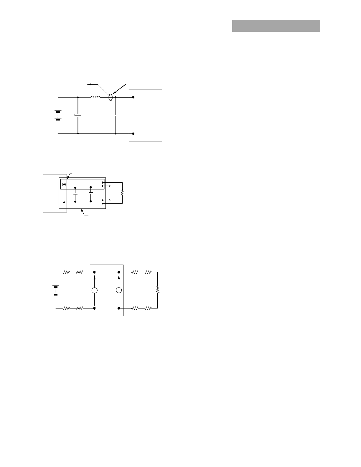
EMC Considerations
The circuit and plots in Figure 29 shows a suggested configuration to meet the conducted emission limits of EN55022 Class B.
Figure 29. EMC Considerations
For further information on designing for EMC compliance, please refer to the FLT007A0 data sheet (DS05-028).
VIN = 48V, Io = Io,max, L Line
April 4, 2013 ©2012 General Electric Company. All rights reserved. Page 13
VIN = 48V, Io = Io,max, N Line
Page 14

GE
Data Sheet
EHHD015A0A Hammerhead™
18-75Vdc Input; 5Vdc, 15.0A, 75W Output
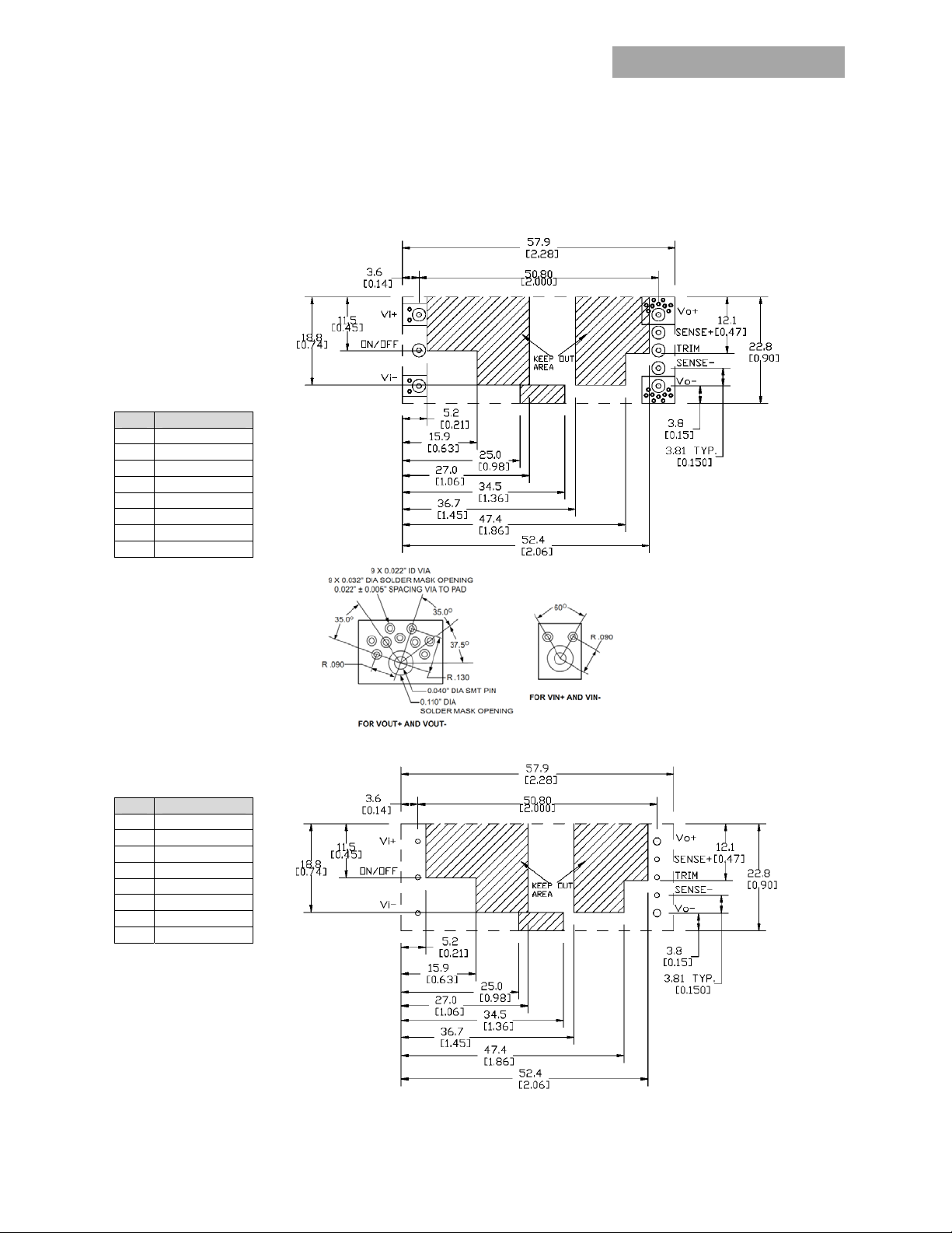
Mechanical Outline for Through-Hole Module
Dimensions are in millimeters and [inches].
Tolerances: x.x mm 0.5 mm [x.xx in. 0.02 in.] (Unless otherwise indicated)
x.xx mm 0.25 mm [x.xxx in 0.010 in.]
*Top side label includes GE name, product designation and date code.
Series; DC-DC Converter Power Modules
April 4, 2013 ©2012 General Electric Company. All rights reserved. Page 14
Page 15

GE
Data Sheet
EHHD015A0A Hammerhead™
18-75Vdc Input; 5Vdc, 15.0A, 75W Output
Mechanical Outline for Surface Mount Module (-S Option)
Dimensions are in millimeters and [inches].
Tolerances: x.x mm 0.5 mm [x.xx in. 0.02 in.] (Unless otherwise indicated)
x.xx mm 0.25 mm [x.xxx in 0.010 in.]
* Top side label includes GE name, product designation and date code.
Series; DC-DC Converter Power Modules
April 4, 2013 ©2012 General Electric Company. All rights reserved. Page 15
Page 16

GE
Data Sheet
EHHD015A0A Hammerhead™
18-75Vdc Input; 5Vdc, 15.0A, 75W Output
Mechanical Outline for Through-Hole Module with Heat Plate (-H Option)
Dimensions are in millimeters and [inches].
Tolerances: x.x mm 0.5 mm [x.xx in. 0.02 in.] (Unless otherwise indicated)
x.xx mm 0.25 mm [x.xxx in 0.010 in.]
Series; DC-DC Converter Power Modules
April 4, 2013 ©2012 General Electric Company. All rights reserved. Page 16
Page 17

GE
Data Sheet
EHHD015A0A Hammerhead™
18-75Vdc Input; 5Vdc, 15.0A, 75W Output
Mechanical Outline for Through-Hole Module with ¼ Brick Heat Plate (-18H Option)
Dimensions are in millimeters and [inches].
Tolerances: x.x mm 0.5 mm [x.xx in. 0.02 in.] (Unless otherwise indicated)
x.xx mm 0.25 mm [x.xxx in 0.010 in.]
Series; DC-DC Converter Power Modules
April 4, 2013 ©2012 General Electric Company. All rights reserved. Page 17
Page 18
GE
Data Sheet
EHHD015A0A Hammerhead™
Series; DC-DC Converter Power Modules
18-75Vdc Input; 5Vdc, 15.0A, 75W Output
Recommended Pad Layout
Dimensions are in millimeters and [inches].
Tolerances: x.x mm 0.5 mm [x.xx in. 0.02 in.] (Unless otherwise indicated)
x.xx mm 0.25 mm [x.xxx in 0.010 in.]
Pin Function
1 Vi(+)
2 ON/OFF
3 Vi(-)
4 Vo(-)
5 SENSE(-)
6 TRIM
7 SENSE(+)
8 Vo(+)
SMT Recommended Pad Layout (Component Side View)
Pin Function
1 Vi(+)
2 ON/OFF
3 Vi(-)
4 Vo(-)
5 SENSE(-)
6 TRIM
7 SENSE(+)
8 Vo(+)
NOTES:
FOR 0.030” X 0.025”
RECTANGULAR PIN, USE
0.050” PLATED THROUGH
HOLE DIAMETER
FOR 0.62 DIA” PIN, USE
0.076” PLATED THROUGH
HOLE DIAMETER
TH Recommended Pad Layout (Component Side View)
April 4, 2013 ©2012 General Electric Company. All rights reserved. Page 18
Page 19

GE
Data Sheet
EHHD015A0A Hammerhead™
Series; DC-DC Converter Power Modules
18-75Vdc Input; 5Vdc, 15.0A, 75W Output
Packaging Details
The surface mount versions of the EHHD015A0A (suffix –S) are
supplied as standard in the plastic trays shown in Figure 30.
Tray Specification
Material Antistatic coated PVC
Max surface resistivity 10
Color Clear
Capacity 12 power modules
Min order quantity 48 pcs (1 box of 4 full trays + 1
12
/sq
empty top tray)
Each tray contains a total of 12 power modules. The trays are
self-stacking and each shipping box for the EHHD015A0A
(suffix –S) surface mount module will contain 4 full trays plus
one empty hold down tray giving a total number of 48 power
modules.
Figure 30. Surface Mount Packaging Tray
April 4, 2013 ©2012 General Electric Company. All rights reserved. Page 19
Page 20

GE
Data Sheet
EHHD015A0A Hammerhead™
Series; DC-DC Converter Power Modules
18-75Vdc Input; 5Vdc, 15.0A, 75W Output
Ordering Information
Please contact your GE Sales Representative for pricing, availability and optional features.
Table 1. Device Codes
Product Codes Input Voltage
EHHD015A0A41Z 24/48V (18-75Vdc) 5.0V
EHHD015A0A641Z 24/48V (18-75Vdc) 5.0V
EHHD015A0A41-HZ 24/48V (18-75Vdc) 5.0V
EHHD015A0A64Z 24/48V (18-75Vdc) 5.0V
EHHD015A0A64-18HZ 24/48V (18-75Vdc) 5.0V
EHHD015A0A41-SZ 24/48V (18-75Vdc) 5.0V
Table 2. Device Coding Scheme and Options
Output
Voltage
Output
Current
15A
15A
15A
15A
15A
15A
On/Off Logic
Negative
Negative
Negative
Positive
Positive
Negative
Connector
Type
Through hole CC109161485
Through hole 150021782
Through hole CC109161980
Through hole CC109171402
Through hole CC109171410
Surface mount CC109161997
Comcodes
Contact Us
For more information, call us at
USA/Canada:
+1 888 546 3243, or +1 972 244 9288
Asia-Pacific:
+86.021.54279977*808
Europe, Middle-East and Africa:
+49.89.878067-280
India:
+91.80.28411633
April 4, 2013 ©2012 General Electric Company. All rights reserved. Version 1.09
www.ge.com/powerelectronics
 Loading...