

Page 1

GEH-6405A
(
Supersedes GEH-6405)
*(,QGXVWULDO6\VWHPV
Control System Toolbox
For Configuring AV-300, DV-300,
and AV-300i (AVDV Series) Drives
Page 2

Page 3

Publication: GEH-6405A
Issued: 1999-06-12
Control System Toolbox
For Configuring AV-300, DV-300,
and AV-300i (AVDV Series) Drives
Page 4

© 1999 General Electric Company, USA.
All rights reserved.
Printed in the United States of America.
These instructions do not purport to cover all details or variations in equipment, nor to provide
every possible contingency to be met during installation, operation, and maintenance. If further
information is desired or if particula r p ro blems arise that are not covered sufficiently for the
purchaser’s purpose, the matter should be referred to GE Industrial Systems, Salem, Virginia,
USA.
This document contains proprietary information of General Electric Company, USA and is
furnished to its customer solely to assist th at customer in the installation, testing, operation,
and/or maintenance of the equipment described. This document shall not be reproduced in whole
or in part nor shall its contents be disclosed to any third party without the written approval of GE
Industrial Systems.
ARCNET is a registered trademark of Datapoint Corporation.
Ethernet is a trademark of Xerox Corporation.
IBM is a registered trademark of International Business Machines Corporation.
Intel is a registered trademark of Intel Corporation.
Pentium is a registered trademark of Intel Corporation.
PC is a registered trademark of International Business Machines Corporation.
Series 90 is a trademark of GE Fanuc Automation North America, Inc.
Windows is a registered trademark of Microsoft Corporation.
Windows NT is a registered trademark of Microsoft Corporation.
Page 5
Safety Symbol Legend
Indicates a procedure or condition that, if no t
strictly observed, could result in personal injury or
death.
Indicates a procedure or condition that, if no t
strictly observed, could result in damage to or
destruction of equipment.
Indicates a procedure or condition that should be
strictly followed in order to optimize these
applications.
Note Indicates an essential or important p r ocedure, condition, or statement.
Page 6
!
Warning
!
Caution
To prevent personal injury or equipment damage
caused by equipment malfunction, only a dequa t e ly
trained personnel should modify any
programmable machine.
The example and setup screens in this manual do
not reflect the actual application configura t ions. Be
sure to follow the correct setup procedures for
your application.
Page 7

Contents
Chapter 1
Introduction ............................................................................................................................ 1-1
Before Beginning................................................................................................................... 1-1
Chapter 2
Introduction ............................................................................................................................ 2-5
Computer Requirements.........................................................................................................2-5
Installing Control System Solutions....................................................................................... 2-6
Chapter 3
Introduction .......................................................................................................................... 3-11
Upgrading from Previous Releases...................................................................................... 3-11
Starting the Toolbox............................................................................................................. 3-12
Accessing Online Help......................................................................................................... 3-14
Privilege/Password ............................................................................................................... 3-14
Toolbox Options .................................................................................................................. 3-17
Connecting the Toolbox ....................................................................................................... 3-21
Overview
How To Use This Manual........................................................................................ 1-1
Conventions............................................................................................................. 1-2
Installation
License Key............................................................................................................. 2-6
Destination Directory............................................................................................... 2-7
Registration License Agreement.............................................................................. 2-8
Product Selection.....................................................................................................2-9
Uninstall Products.................................................................................................... 2-9
Using the Toolbox
Maintaining Multiple Releases of Toolbox ........................................................... 3-11
Work Area ............................................................................................................. 3-12
General................................................................................................................... 3-17
Directories.............................................................................................................. 3-18
Trend Recorder......................................................................................................3-19
AVDV Series Drive............................................................................................... 3-20
1-1
2-5
3-11
Chapter 4
GEH-6405 Toolbox for an AVDV Series Drive Contents • i
Configuring an AVDV Series Drive
Introduction .......................................................................................................................... 4-23
Creating an AVDV Series Drive.......................................................................................... 4-23
Pattern and Version................................................................................................ 4-24
Enter User Identification........................................................................................ 4-25
Configuring the Drive..........................................................................................................4-26
Toolbox Work Area............................................................................................... 4-26
Entering Job Specific Information......................................................................... 4-28
Working with Files and Menus............................................................................................ 4-29
File Types .............................................................................................................. 4-29
4-23
Page 8

Opening and Closing Files..................................................................................... 4-30
Saving Files............................................................................................................4-30
Upgrading a Configuration....................................................................................4-31
Select Upgrade Version......................................................................................... 4-31
Exporting Configuration Files...............................................................................4-32
Exporting/Opening Project Files............................................................................ 4-32
Menu Commands................................................................................................... 4-33
Concepts............................................................................................................................... 4-39
Configuration.......................................................................................................................4-40
Parameters.............................................................................................................. 4-40
Toolbox/Drive Communications............................................................................4-42
Connecting to an AVDV Series Drive................................................................... 4-43
Block Diagram.....................................................................................................................4-44
Links to Other Pages.............................................................................................. 4-45
Modify Parameters from Diagram......................................................................... 4-45
Parameter Jumpers................................................................................................. 4-46
Live Data Display..................................................................................................4-46
Drag-and-Drop Variables.......................................................................................4-46
Printing Diagrams.................................................................................................. 4-47
Drive Controls...................................................................................................................... 4-47
Wizards................................................................................................................................ 4-48
Choose Wizard....................................................................................................... 4-48
Uploading Parameters.......................................................................................................... 4-49
Fault Display........................................................................................................................ 4-50
Self-tune............................................................................................................................... 4-51
Self-tune the Drive................................................................................................. 4-51
DV-300 Current Tune............................................................................................ 4-53
Using the Finder................................................................................................................... 4-53
Finder Window......................................................................................................4-54
Glossary of Terms G-1
ii • Contents GEH-6405 Toolbox for an AVDV Series Drive
Page 9

Chapter 1
Introduction
The toolbox software configures
various control equipment.
Therefore, each product package
can consist of the toolbox,
product files for the drive, and
Trend Recorder. To order the
toolbox software and specific
product support files, refer to the
Product Catalog, GEP-9145.
Overview
This manual describes the Control System Toolbox, which is micro-processor-based
software used to configure and maintain AV-300™, DV-300™, and AV-300i™,
(AVDV Series) drives. The toolbox is a Windows
a Pentium
Primary functions of the toolbox include:
•
Configuratio n wizar d s
•
Live data block flow diagrams
•
Online Help files
•
I/O configuration and monitoring
•
Signal management and signal trending
•
Generate report(s)
®
100 or higher, personal computer (PC).
®
-based application, which runs on
Before Beginning
Windows-based screen
borders may vary in
appearance.
GEH-6405 Toolbox for an AVDV Series Drive Chapter 1 Overview • 1
This manual describes the features of the toolbox and presents step-by-step
procedures for using the software applications provided. It presumes that the user
has already installed Windows. This manual also assumes t hat the user possesses at
least a medium-level knowledge of Windows. Hardware requirements and
instructions for installing the products are in Chapter 2.
How To Use This Manual
This manual provides the user with information on installing the toolbox and other
products used to configure control equipment. It also describes other features
provided in the toolbox software package. This manual is organized as follows:
Chapter 1 Overview. This chapter defines functionstures of the toolbox, contents
of this manual, and the conventions used.
Chapter 2 Installation. This chapter describes the PC and installation requirements
for the AVDV Series drives.
Page 10

Chapter 3 Using the Toolbox. This chapter provides basic startup procedures and
features for using the toolbox to configure a product.
Chapter 4 Configuring an AVDV Series Drive. This chapter describes how to use
the toolbox to configure a drive.
Glossary. The Glossary provides definitions of configuration terms and toolbox
concepts.
Refer to the Table of Contents for the organization of these chapters.
Conventions
The following conventional terms, text formats, and symbols are used throughout
this documentation for the toolb ox.
Convention Meaning
Bold
Arial Bold
Italic Indicates a word used as a word or a letter used as a letter. For
UPPERCASE
Monospace
À
w
•
The following list presents some basic guidelines for working with menus:
When a menu is displayed, press the up/down arrow keys to highlight a command
name. Then press Enter to choose the menu command. The menu can also be
selected by clicking with a cursor-positionin g de vice (CPD), such as a mouse.
Indicates that the word is being defined.
Indicates the actual command or option that is chosen from a
menu or dialog box.
example, the display should now read SDB has stopped. Italic
also indicates new terms, margin notes, and the titles of figures,
chapters, and other books in the toolbox package.
Indicates a directory, filename, or block name. Lowercase letters
can be used when typing names in a dialog box or at the
command prompt, unless otherwise indicated for a specific
application or utility.
Represents examples of screen text or words and characters that
are typed in a text box or at the command prompt.
Indicates a procedure.
Indicates a procedure with only one step.
Indicates a list of related information, not procedural steps.
When a command ends in an ellipsis (…), the application displays a dialog box that
asks the user to supply more information.
If a command turns a feature on and off, a checkmark (ä) is displayed by the
command name when the feature is on.
When a command ends with an arrow (
command names.
If a command name is grayed out, it indicates that the command does not apply to
the current situation or there is another selection or action before choosing the
command.
2 • Chapter 1 Overview GEH-6405 Toolbox for an AVDV Series Drive
), the menu cascades to display more
Page 11

Related Publications
GE provides system instruction manuals that include publications for the different
components of each product. If additional manuals are needed or for questions about
the publications, contact the nearest GE sales office or authorized GE sales
representative. Also, refer to the following publications for more i nformation about
AVDV Series equipment:
•
GEI-100331, AV-300 Adjustable Speed Drives
•
GEI-100360, AV-300I Adjustable Speed Drives
•
GEI-100332, DV-300 Adjustable Speed Drives
•
GEI-100275, 6KCV300CTI Instruction Book
GEH-6405 Toolbox for an AVDV Series Drive Chapter 1 Overview • 3
Page 12

Notes
4 • Chapter 1 Overview GEH-6405 Toolbox for an AVDV Series Drive
Page 13

Chapter 2
Introduction
Installation
This chapter describes the PC and installation requirements for the products in
Control System Solutions. The contents of this CD depends on which products are
ordered. Some orders are issued a License Key. Available products display in the
Product Selection dialog box (see the section, Product Selection).
Section Page
Computer Requirements..............................................................................................1
Installing Control System Solutions ............................................................................2
License Key.................................................................................................................2
Destination Directory...................................................................................................3
Registration License Agreement..................................................................................4
Product Selection.........................................................................................................5
Uninstall Products........................................................................................................5
Computer Requirements
The minimum PC requirements are determined by the selected product combination
and the topology configuration of the PC(s). The minimum requirements to use the
Control System Solutions products are as follows:
•
100 MHz processor (Pentium 166 or higher recommended)
A cursor-positioning device is
highly recommended.
GEH-6405A Toolbox for an AVDV Series Drive Chapter 2 Installation • 2-1
•
Microsoft
•
VGA display (640 x 480 x 16 color or gray scale)
• 16 MB RAM in Windows 95 (32 MB recommended) or 24 MB RAM in
Windows NT (32 MB recommended)
• Serial port for direct connection to a drive
• Printer (with appropriate Windows driver installed)
®
Windows® 95 or Windows NT® 4.0
Page 14
Installing Control System Solutions
For assistance, contact:
Industrial Systems
General Electric Company
Product Service Engineering
1501 Roanoke Blvd.
Salem, VA 24153-6492 USA
Phone + 1 540 387 7595
Fax + 1 540 387 8606
(replace + with the
international access code)
Install the desired products
from CD, following the
directions on the screen.
Then, install each product
file.
Control System Solutions installs various pro ducts for control systems a s selected in
the setup program. It is recommended that you exit all Windows programs before
beginning. A dialog box may prompt you for a License Key, which can be found on
the actual CD. Also, you must agree to the standard Software License Agreement for
these products.
A default destination directory is set for all products selected. This directory can be
modified, but only during the first installation. Setup installs the required
components and checks available disk space before copying files. You can also
choose to cancel setup and exit at any time before you initiate the selected products.
À To install from a CD
1. Place the Control System Solutions CD in the disk drive.
2. The Setup program executes automatically.
3. Follow the Setup instructions from the screen.
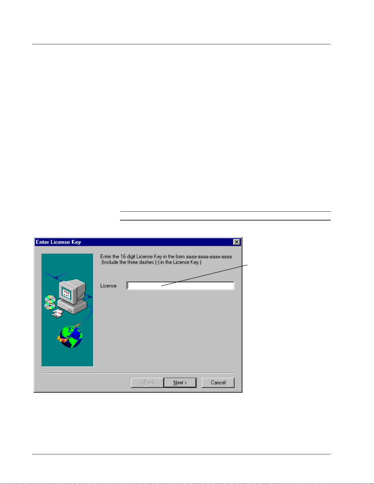
License Key
Note The License Key dialog box may appear, depending on the products ordered.
Enter the License Key number.
This number is printed on the
actual CD. The number is not
case sensitive.
2-2 • Chapter 2 Installation GEH-6405A Toolbox for an AVDV Series Drive
Page 15
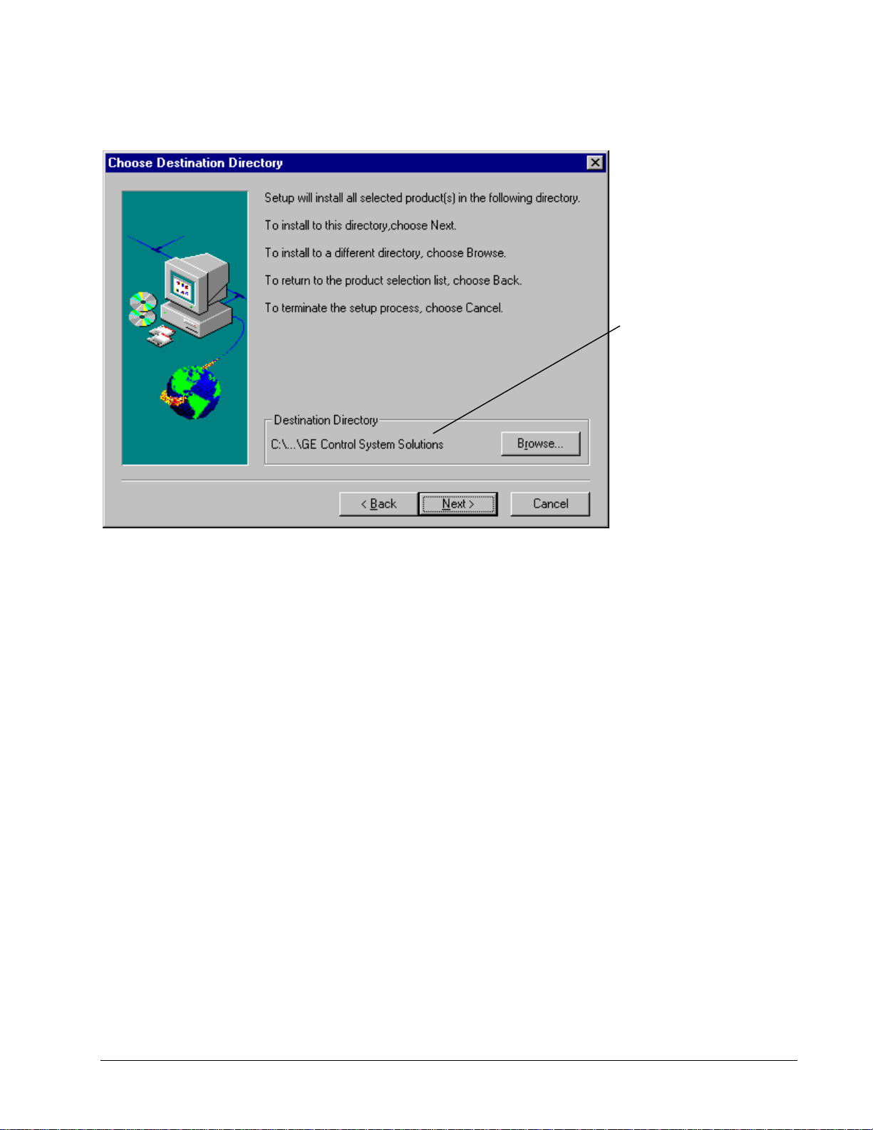
Destination Directory
The destinat io n directory for
each product is set to the
default directory C:\Program
Files\GE Control System
Solutions. If desired select a
different directory to load the
products.
This dialog box option can
only be selected during the
initial installation of these
products. After that all future
installs and upgrades default
to the first directory selected.
Select a directory and click Next. Setup automatically continues to load. The Control
System Solutions product selection dialog box displays to allow you to select desired
products described in the following sections.
GEH-6405A Toolbox for an AVDV Series Drive Chapter 2 Installation • 2-3
Page 16
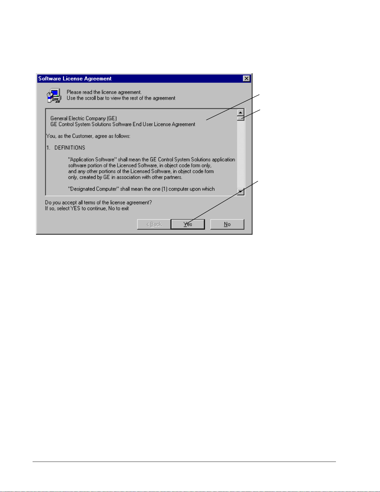
Registration License Agreement
The following License Agreemen t dialog box displays during installation. The
license must be read and agreed to before installation can continue.
Please read the entire
agreement (scroll bar must
be at the bottom of the
dialog box).
Click Yes to accept the
agreement.
2-4 • Chapter 2 Installation GEH-6405A Toolbox for an AVDV Series Drive
Page 17
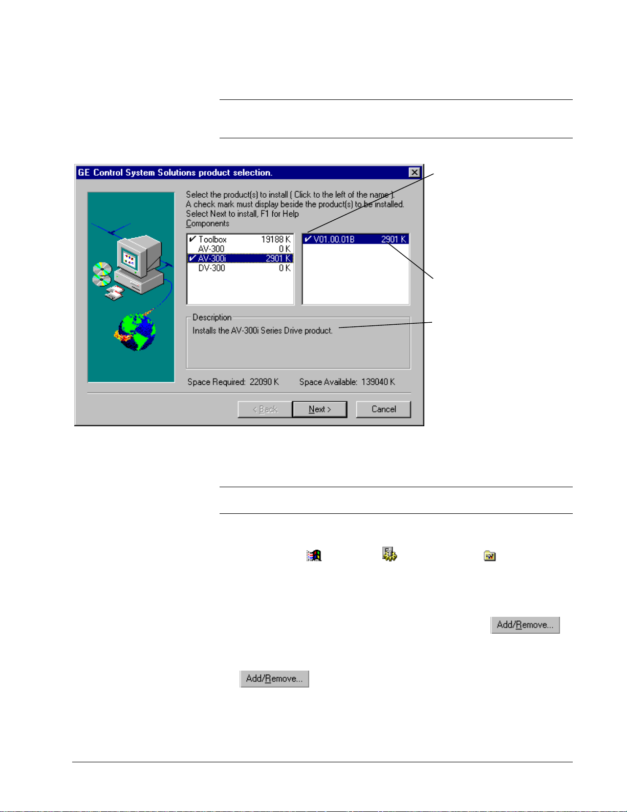
Product Selection
Tip
À From the Product Selection dialog box, click on a product (highlight) to
display its description and required disk space. The total required space for all
checked items and the space available displays at the bottom of the dialog box.
You must click to the left of each
product you want to install. A
check mark must display beside
the product name.
Click the product name in the left
column to check all the
application in that group. Click
again to uncheck all.
The number beside each product
indicates the amount of space
required for that product.
A description of each product
displays when it is selected
(highlighted).
Uninstall Products
Note
Before upgrading to Release 5, product components should be uninstalled and
then installed again using the Release 5 CD or network installation.
À To uninstall product(s)
1. Click Windows
2. From the Control Panel dialog box, double-click on Add/Remove
Programs. The Add/Remove Program Properties dialog box displays.
3. Click on the tab Install/Uninstall. A list of all installed programs displays.
4. From the list box, click on the progra m to uninstall and click
– Or –
To remove all Control System Solution products, click Uninstaller and click
The following screen displays to show when uninstall is complete and the status of
all items deleted.
Start button, Settings and click Control Panel.
.
.
GEH-6405A Toolbox for an AVDV Series Drive Chapter 2 Installation • 2-5
Page 18

If you choose to remove all products by selecting
Uninstaller, the following dialog box displays. All
installed products are listed and will be removed.
2-6 • Chapter 2 Installation GEH-6405A Toolbox for an AVDV Series Drive
Page 19

Chapter 3
Introduction
Using the Toolbox
Settings in the Options menu
should be determined before
starting a configuration.
This chapter provides basic instructions for using the toolbox. It defines the toolbox
menu commands, includi ng the Options menu, which has a Settings dialog tab for
each product. Methods of communication and toolbox connections are also
described.
Section Page
Upgrading from Previous Releases..............................................................................2
Starting the Toolbox ....................................................................................................3
Accessing Online Help ................................................................................................5
Privilege/Password.......................................................................................................5
Toolbox Options..........................................................................................................8
Connecting the Toolbox.............................................................................................12
GEH-6405A Toolbox for an AVDV Series Drive Chapter 3 Using the Toolbox • 3-1
Page 20

Upgrading from Previous Releases
Note
To upgrade to Version 5 of the toolbox, it is recommended that you first
uninstall any previous version of toolbox.
Maintaining Multiple Releases of Toolbox
To maintain different releases of the toolbox on a single system, consider the
following:
•
Multiple versions of Release 5 cannot be insta lled on one system. The
installation directory for Release 5 of the toolbox is chosen only once, the first
time that the Control System Solutions products are installed. The default
directory is C:\Program Files\GE Control System Solutions.
•
There is only one set of toolbox options settings for a given user on a given
computer. There are several toolbox options settings that may need to be
unique to a particular release of toolbox. For example, Release 4 of the toolbox
would probably need a different directory setting for standard library .tre files
than that of Release 5. In order to use multiple releases, it is recommended to
use different user accounts for each release.
•
Opening a toolbox file from the Windows Explorer is not recommended if
multiple copies of toolbox are installed. When you op e n a file from the
Windows Explorer, the application that starts up depends on what is registered
for that file type. Releases of toolbox prior to Release 5 register each time they
execute. Release 5 of toolbox, however, registers only at installation.
•
Modifying a toolbox file can make the file unusa ble to older releases of
toolbox. A warning dialog displays when the toolbox opens a file that was
written by a previous release. Do not save the file i f it must be used by the
previous release.
3-2 • Chapter 3 Using the Toolbox GEH-6405A Toolbox for an AVDV Series Drive
Page 21
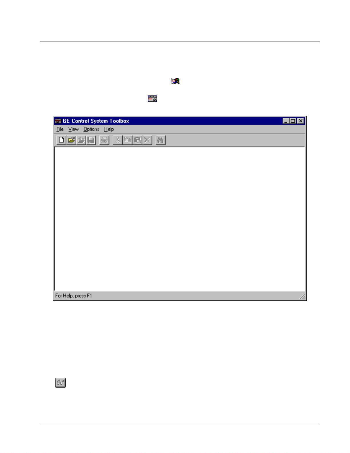
Starting the Toolbox
The toolbox is started from the Windows NT or 95 Workstation.
À To start the toolbox
To create a device, refer to
Chapter 4.
1. Click Windows
Solutions and GE Control System Toolbox.
2. Click
device is created or opened.
the toolbox icon. The toolbox Work Area displays. It is blank until a
Start button, Programs, GE Control System
Work Area
If more than one drive is open
in the Work Area, each drive
will have a window with an
Outline View and Summary
View.
Click
Detached Summary View.
GEH-6405A Toolbox for an AVDV Series Drive Chapter 3 Using the Toolbox • 3-3
to display the
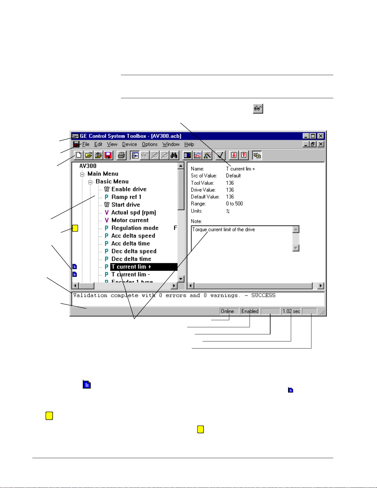
A drive’s runtime action is configured using the toolbox. From the File menu, begin
a New configuration or Open a previously saved configuration file. The toolbox
Work Area (shown below) is the main screen and contains the following:
Outline View (left side) displays the configuration in a hierarchy, with the drive
name as the first item and other configuration items listed in levels below it.
Summary View (right side) displays information for the item highlighted in the
Outline View. For example, in a drive configuratio n, the item Diagram displays
block diagrams (which can be configured from this view).
Detached Summary View is a separate window from the Work Area window and
displays a copy of the Diagram. This window can be sized, configured, and edited.
Page 22
To find the cause of an error,
double-click on the error
message.
Log View (bottom of window) displays status messages for toolbox activities, such
as file imports, validations, builds, or errors.
Note The following screen represent a basic toolbox Work Area format. Menu
commands, toolbar button, and Outline V iew items will vary with the product
installed.
Title bar
Menu bar
Toolbar
Outline
View
Bookmark
Notes
Log
View
Summary View display details of the item selected
in the Outline View. For example, the parameter
current Lim+
is shown below.
Click to display the Detached
T
Summary View. This view displays
details of Diagram (an overall picture
of the block diagrams).
Status bar
displays
toolbox
information
on the right
and drive
information
on the left
side.
For Help, Press F1
From the Outline View, click on an
item with a Note icon. The note
displays in the Summary View .
Communication status
Drive status
Fault indication
Diagram scan rate
Read only file
Status Bar can be toggled on and off from the View menu. When online, the left
side displays a description of various toolbox commands or notes entered by the
user. The right-hand side displays the drive status of the current drive.
Double click on the
Note
icon to edit the note.
Bookmark items display this
icon
3-4 • Chapter 3 Using the Toolbox GEH-6405A Toolbox for an AVDV Series Drive
.
Notes can be created for most items in the drive. Choose an item, then choose Edit
and Modify. Enter a note for the item and click OK. The Note icon
displays
beside the item in the Outline View (shown above).
Bookmark enables you to mark major items in the Outline View and then return to
them easily using the Bookmark commands in the Edit menu. The Toggle Bookmark
command turns the icon on and off. The Goto Next Bookmark command jumps to
the next item marked with the
.
Page 23
Accessing Online Help
A
I
To obtain Help for the dialog
box on the screen, press
F1
Specific dialog box Help is available by pressing the F1 function key, when a dialog
box is displayed. Help can also be accessed using the following methods:
.
To obtain Help on . . . Do this . . .
Menu commands Highlight the command and press F1
Dialog boxes Press F1 when the dialog box displays on the screen
Block information Click on the desired block with the right mouse button
Help contents Choose the Help menu and choose Contents
Help Choose the Help menu and choose Using Help
Specific word(s) Choose the Help menu, choose Contents, and choose
Privilege/Password
Refer to the next section to
change the password.
To avoid this dialog box,
choose Options menu,
Settings, and the tab General.
t the bottom of the dialog
box in the text box User
dentification, enter your
user ID.
The privilege/password system assigns different levels of access to the devices.
Then, passwords can be established for the different privilege levels, so that each
user can access a device at the level necessary for the job that person is assigned.
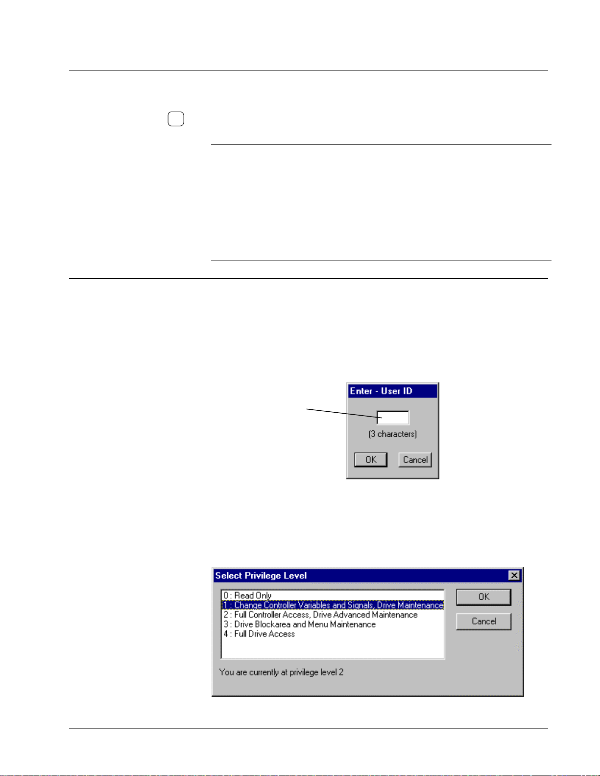
À To set a privilege level
w From the Options menu, choose Privilege.
Enter a three-character ID,
such as your initials.
Click OK.
and choose Item Help
the tab Find, then enter the word(s) to search
Privilege Level Functions
A password can be assigned to each of the five toolbox privilege levels defined
below. Each successive level allows all the functions of the previous level. The
levels are defined in the table, Privilege Levels (below).
GEH-6405A Toolbox for an AVDV Series Drive Chapter 3 Using the Toolbox • 3-5
Page 24

Privilege Levels
Level Functions
0: Read Only View code
Use the Finder
Monitor live data
Trend (including saving trend definitions in .TRN
files and saving collected data)
Change View attributes under Option menu/
Settings
Print blockware code and reports
Change the password for level 0
1: Change drive Advanced
Maintenance
2: Full drive Advanced
Maintenance
3: Drive Block Area and Menu
Maintenance
4: Full Drive Access Change GE parameters
All functions allowed in Level 0, including change
password levels in Levels 0 and 1
Change the value of variables
All functions allowed in Level 0 and Level 1
Make code changes
Download
Import/Export
Put in database and Get from database
Validate, build, save, backup, and pack signals
Change the password for Levels 0, 1, and 2
Change the location of the password file
Alter block area and change application menu
structure
View parameters that are not on a menu
Edit Hardware
3-6 • Chapter 3 Using the Toolbox GEH-6405A Toolbox for an AVDV Series Drive
Page 25

Enter the old password
in text box 1) and press
the Tab key.
Enter the new password
in textbox 2) and press
the Tab key.
Enter the new password
again in text box 3) to
verify it is correct.
Tab
Tab
À To change the password
1. From the Options menu, choo se Passw ord . The Changing password
dialog box
displays.
2. Click on the privilege level to change.
3. Click OK. The Changing password dialog box displays to enter the new
password.
Change Password or Default Password Directory
When a password is created, it is encoded in the file UCPASSWD.INI in the
Windows NT installation directory. This default directory can be changed, if the user
has a privilege level 2.
À To change the default password file directory
w From the Options menu, choose Settings, and then choose the tab General.
Enter a directory or choose a directory
from Browse…
Enter three characters that identify the current user. You
will not be prompted for initializations when values change.
Note
It is recommended that the password file be kept o n the local PC to avoid loss
of access in the case of downtime on a remote node.
GEH-6405A Toolbox for an AVDV Series Drive Chapter 3 Using the Toolbox • 3-7
Page 26

Toolbox Options
Option settings are saved in
the user’s Windows registry
when the toolbox is closed.
Choose a font for the
Outline View. The default
font is System Bold.
Choose from the following
File options:
Load last file on startup
automatically loads the last
file that was in use when
the toolbox was exited.
The toolbox’s working environment can be defined for each application. This section
describes each tab that can be set to customize the drive, such as general settings,
directories, and the Trend Recorder. These tabs are located in the Options menu
under Settings.
À To customize the toolbox settings
1. From the Options menu, click Settings. The Setting dialog box displays.
Click on a tab to bring it to the fro nt and select options.
2. Choose OK to apply the changes and close the dialog box. Choose Cancel to
exit and not change any settings. Or, choose Apply to install the change
immediately and continue to customize other tab settings.
General
Click this check box to skip a
Choose a font for the
Finder.
level of verification menus and
process changes more quickly.
Backup files before save
makes a backup copy of
files before saving new
information. This includes
.ucb, .dcb, .icb, and .ocb.
Use compact export
format
compresses the .tre
files produced by
exporting. This uses less
hard disk space and is
easier to read and edit.
This setting is
recommended.
Compress files when
saving
files in a compressed
format and save disk
space.
Save bookmarks in files
saves bookmarks between
closing and reopening files.
saves and stores
Enter three character
initials, which are used in
the privilege/password.
You will not be prompted
for initializations when
values change.
Choose an alternate
language that the toolbox
can use to for the
database and diagnostic
symbol table. The default
is English.
Choose the directory for the
password file. A local
directory is recommended.
Browse…
Click
the directory structure and
choose a location.
to search
3-8 • Chapter 3 Using the Toolbox GEH-6405A Toolbox for an AVDV Series Drive
Page 27

Enter the default directory
that will displays when
File/Open is selected.
Directories
GEH-6405A Toolbox for an AVDV Series Drive Chapter 3 Using the Toolbox • 3-9
Page 28

Trend Recorder
The Trend Recorder tab allows you to choose specific options as follows:
Check
Horizontal
Lines to display horizontal
grid lines when in Replay
mode.
Check
Vertical Grid
Lines
to display vertical
grid lines in Replay mode.
Check
Right Vertical Axis
to display vertical axis on
the right-hand side of the
Trend Recorder.
Click here to automatically
configure the Trend
Recorder with predefined
signals. (This feature
currently only works with
Innovation Series drives
and when performing
MarkVI I/O board
calibrations.)
Grid
Select the font size used in the
upper window of the Trend
Recorder.
Signal List Font sets the font
type and size used in the
lower window of the Trend
Recorder.
Click here to zoom in the
Trend Recorder, using the
mouse to drag-and drop a
rectangle on the screen.
Click here for a Yes/No
confirmation prompt to
display before the zoom
takes place.
Click here to
display the amount
of reserved
memory that was
used.
Select the default
pen width
(measured in pixels)
used to draw the
signal traces.
This sets the amount of memory
the toolbox reserves for storing
traces. The default value of 2 MB
allows 4 signals to be captured at
32 ms intervals for about 14
minutes before the oldest data
starts to be overwritten.
3-10 • Chapter 3 Using the Toolbox GEH-6405A Toolbox for an AVDV Series Drive
Page 29

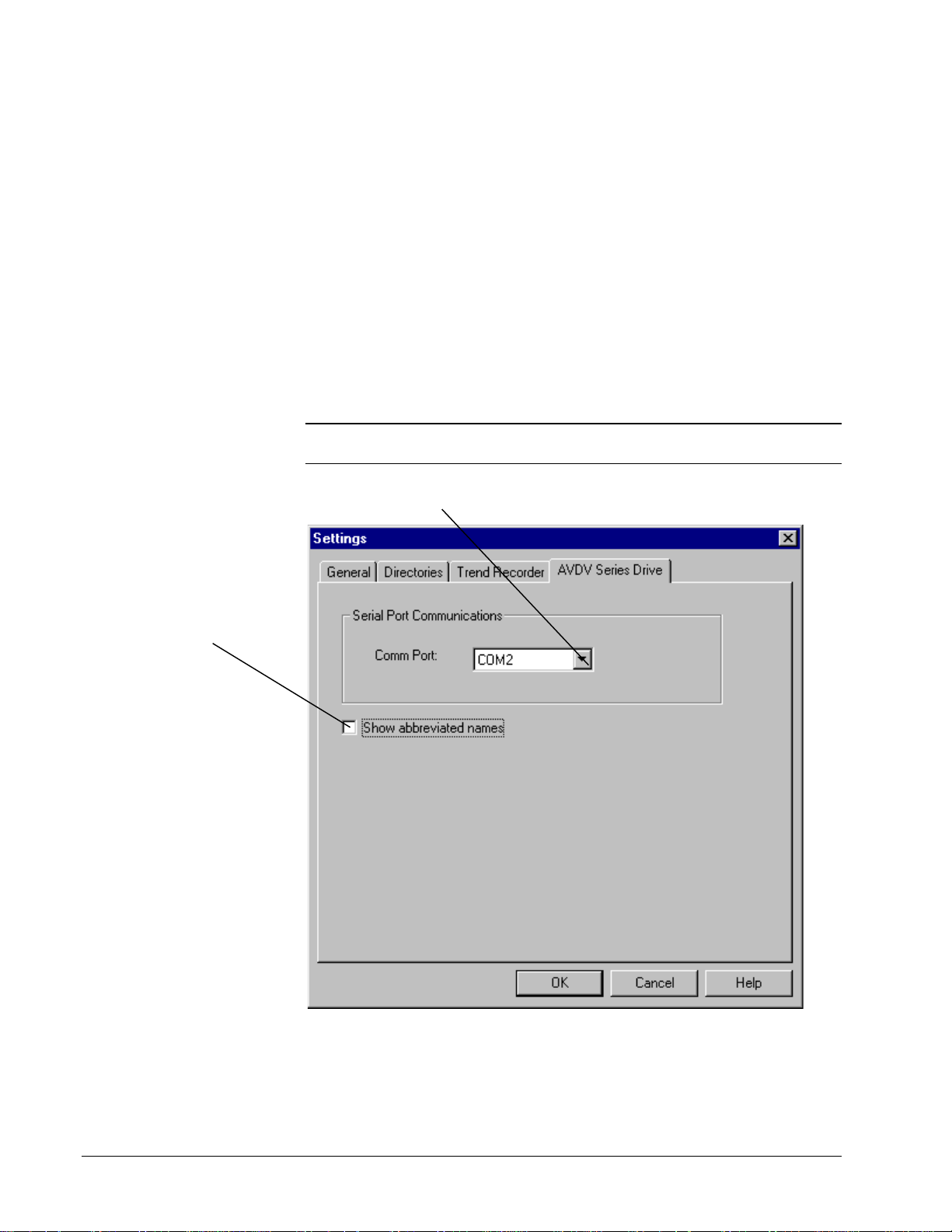
This option changes the
names used on the
diagrams and Outline View
to internal names used
mainly by firmware
developers.
be checked.
It should not
AVDV Series Drive
The AVDV Series Drive tab allows you to choose options specific to the drive.
Click on the drop-down box to choose the
communication port.
GEH-6405A Toolbox for an AVDV Series Drive Chapter 3 Using the Toolbox • 3-11
Page 30

Connecting the Toolbox
The drive requires an RS232C to RS-485 converter
(6K6V300CTI).
9-pin
socket
AV-300
or
DV-300
or
AV-300i
9-pin
socket
AV-300
or
DV-300
or
AV-300i
Drive
9-pin
plug
A - RS-485
Multidrop
Selection
0 V Power
A - RS-485
+5 V Power
9-pin
plug
A - RS485
Multidrop
Selec tion
0 V Power
A - RS-485
+5 V Power
The toolbox can communicate with an AVDV Series drive through an RS-232C/RS485 serial port connection. Refer to the manual, GEI-100275, 6KCV300CTI
Instruction Book.
Note To connect to a drive, refer to the section Connecting to an AVDV Series
Drive. Only one drive at a time can go online (communicate).
9-pin
socket
5/8
9-pin
socket
3
3
4
5
7
9
A - RS-485
4
5
A - RS-485
7
+5 V Power
9
Multidrop
Selection
0 V Power
9-pin
plug
3
4
5
7
PCI - 485
9
RS-232C
2
RX
3
TX
4
DTR
5
Gnd
6
DSR
7
6KCV300CTI
RTS
8
CTS
Terminating resistors switched off
Point to Point Communication
9-pin
socket
A - RS-485
3
4
5
7
9
3
4
5
7
9
Multidrop
Selection
0 V Power
A - RS-485
+5 V Power
9-pin
plug
9-pin
socket
3
4
5
7
PCI - 485
9
RS-232C
2
RX
3
TX
4
DTR
5
Gnd
6
DSR
7
6KCV300CTI
RTS
8
CTS
9-pin
plug
9-pin
plug
2
3
4
5
PC
6
7
8
2
3
4
5
6
PC/toolbox
7
8
Terminating resistors switched on
0 V +5V
5/8
external dc
power supply
2.5 A for 32 drops
9-pin socket 9-pin plug
AV-300
or
DV-300
or
AV-300i
Drive
A - RS-485
Multidrop
Selection
0 V Power
A - RS-485
+5 V Power
3
4
5
7
9
Up to 32
Drives
Multidrop Communication
3-12 • Chapter 3 Using the Toolbox GEH-6405A Toolbox for an AVDV Series Drive
Page 31

Chapter 4
Drive
Introduction
Configuring an AVDV Series
This chapter provides instructions for using the toolbox to configure and monitor an
AVDV Series drive. It also contains information on using other features of the
toolbox specific to the drive.
Section Page
Creating an AVDV Series Drive..................................................................................2
Configuring the Drive ..................................................................................................5
Working with Files and Menus....................................................................................8
Concepts ....................................................................................................................19
Configuration.............................................................................................................20
Block Diagram ...........................................................................................................24
Drive Controls............................................................................................................27
Wizards......................................................................................................................28
Uploading Parameters................................................................................................29
Fault Display..............................................................................................................30
Self-tune.....................................................................................................................31
Using the Finder.........................................................................................................33
Genius Configuration.................................................................................................35
GEH-6405A Toolbox for an AVDV Series Drive Chapter 4 Configuring an AVDV Series Drive • 4-1
Page 32
Creating an AVDV Series Drive
When the toolbox starts, the toolbox Work Area displays (refer to the section,
Configuring the Drive). The Work Area is used to maintain the drive configuration
file in the toolbox. You must create a new drive configuration file (.acb) or open an
existing one.
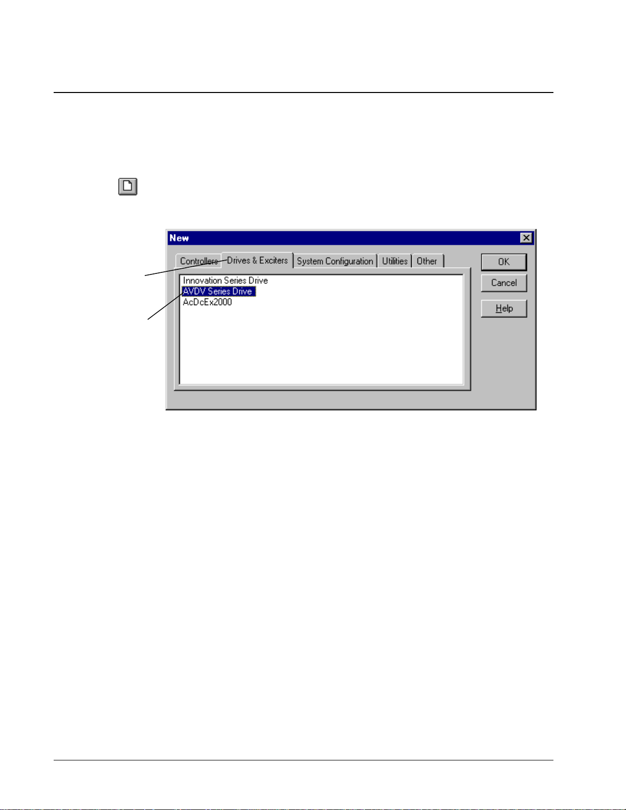
À To create an AVDV Series drive
Or choose the
button.
Click on the tab,
Drives & Exciters.
Click on Innovation
Series Drive and
click OK.
New
w From the File menu, choose New. The New dialog box contains all installed
toolbox products. Choose the drive as follows:
4-2 • Chapter 4 Configuring an AVDV Series Drive GEH-6405A Toolbox for an AVDV Series Drive
Page 33
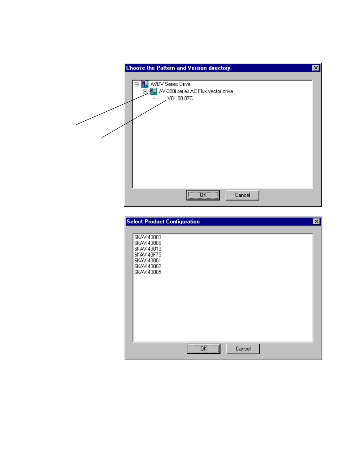
Pattern
Pattern and Version
Choose a
Click OK.
The
Configuration
displays.
Select a configuration file
that sets the values for
the particular bridge size
being configured. Obtain
this number from the
drive nameplate
drive being configured.
Version
Select Product
dialog box
on the
.
GEH-6405A Toolbox for an AVDV Series Drive Chapter 4 Configuring an AVDV Series Drive • 4-3
Page 34
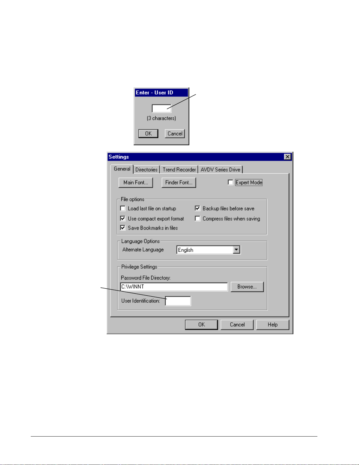
Enter User Identification
To view these configuration
changes with User ID, choose
the View menu and Reports.
If the Enter - ID dialog box (shown below) displays, you must enter an ID to
identifies the user about to make changes to the configuration.
You must enter a three character ID
(such as your initials).
If you are using the curent login on
your PC and the only user making
changes with the toolbox, you can
permanently avoid this dialog box by
entering your ID. Choose the
menu,
Settings
, and the tab
Option
General.
Enter your three
character
identification here
to avoid the
Enter-User ID
dialog box above.
4-4 • Chapter 4 Configuring an AVDV Series Drive GEH-6405A Toolbox for an AVDV Series Drive
Page 35
Configuring the Drive
The Toolbox Work Area is the main screen of an AVDV Series drive configuration
(see screen below). This area is used to configure the drive. Across the top of this
screen is the Title Bar, which contains the name of t he toolbox and the name of the
file (drive configuration) in use. Under the title bar is the Menu Bar containing all
available menu commands. These commands are described in the section, Working
with Files and Menus.
Toolbox Work Area
Tip ¬ To expand or collapse an item in the Outline View, use the mouse and click
on . Or, use the left and right arrow keys to expand/collapse the list. To navigate
through the items in the hierarchy list, use the up and down arrow keys.
Title bar
Toolbar
Outline
View
Log
View
Summary View displays detailed information for
each item in the Outline View and diagram
drawings, when Diagram is selected (shown below).
The Detached Summary View
displays Diagram.
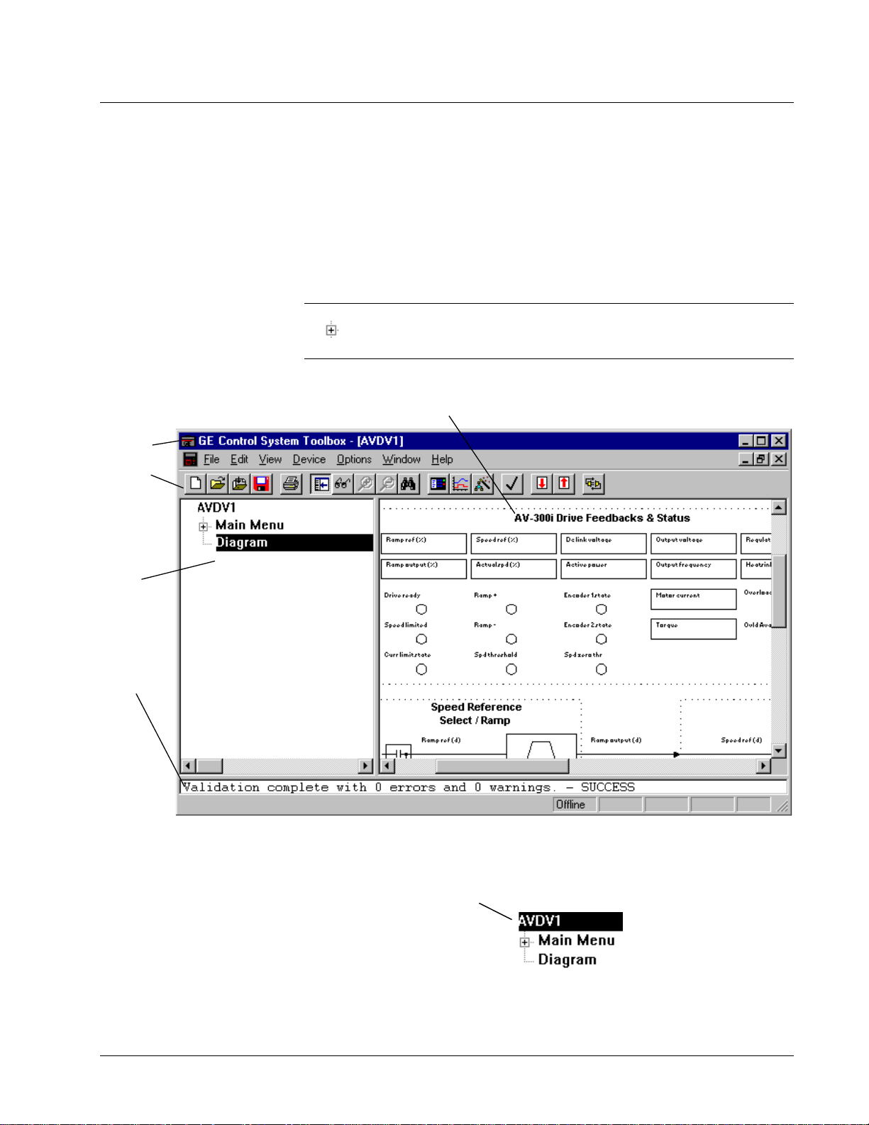
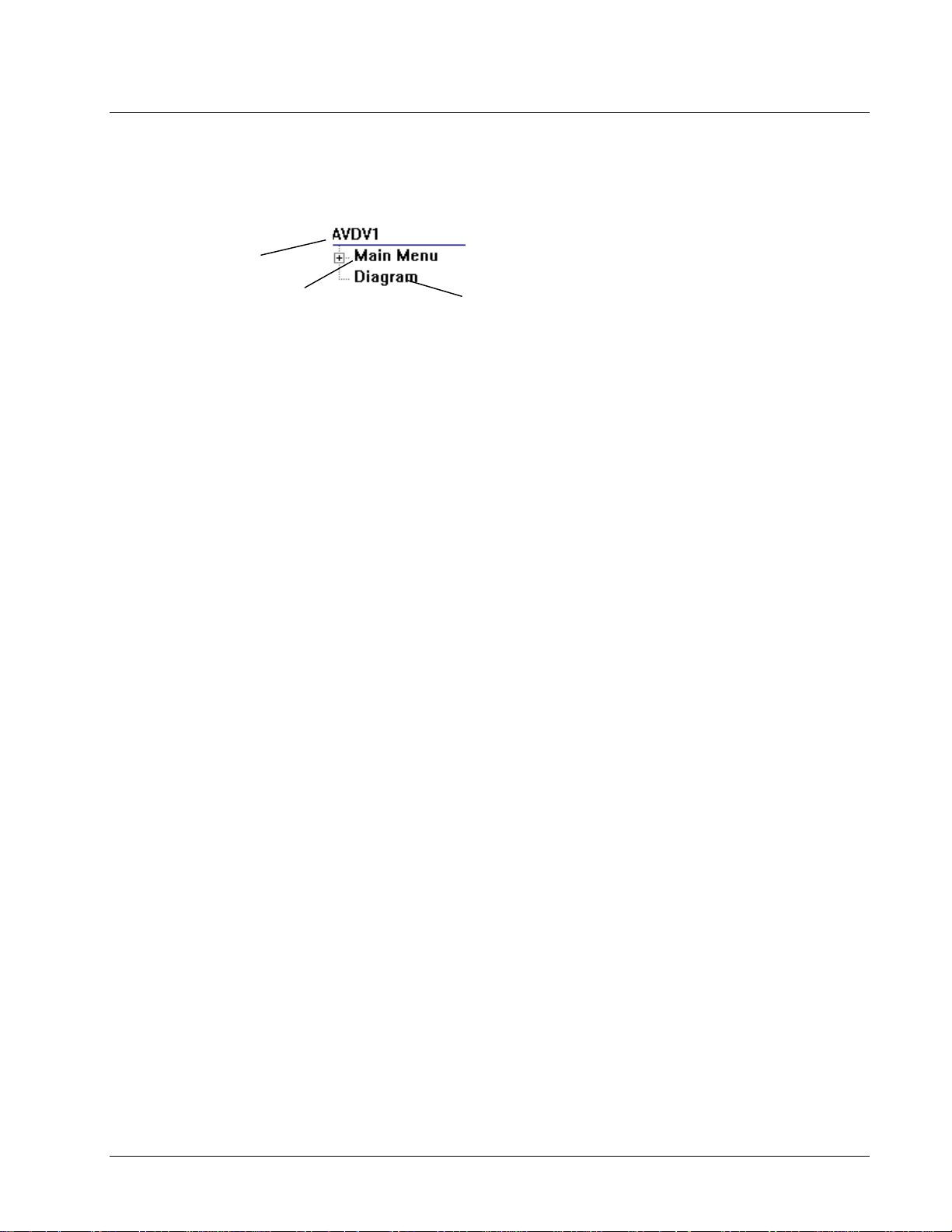
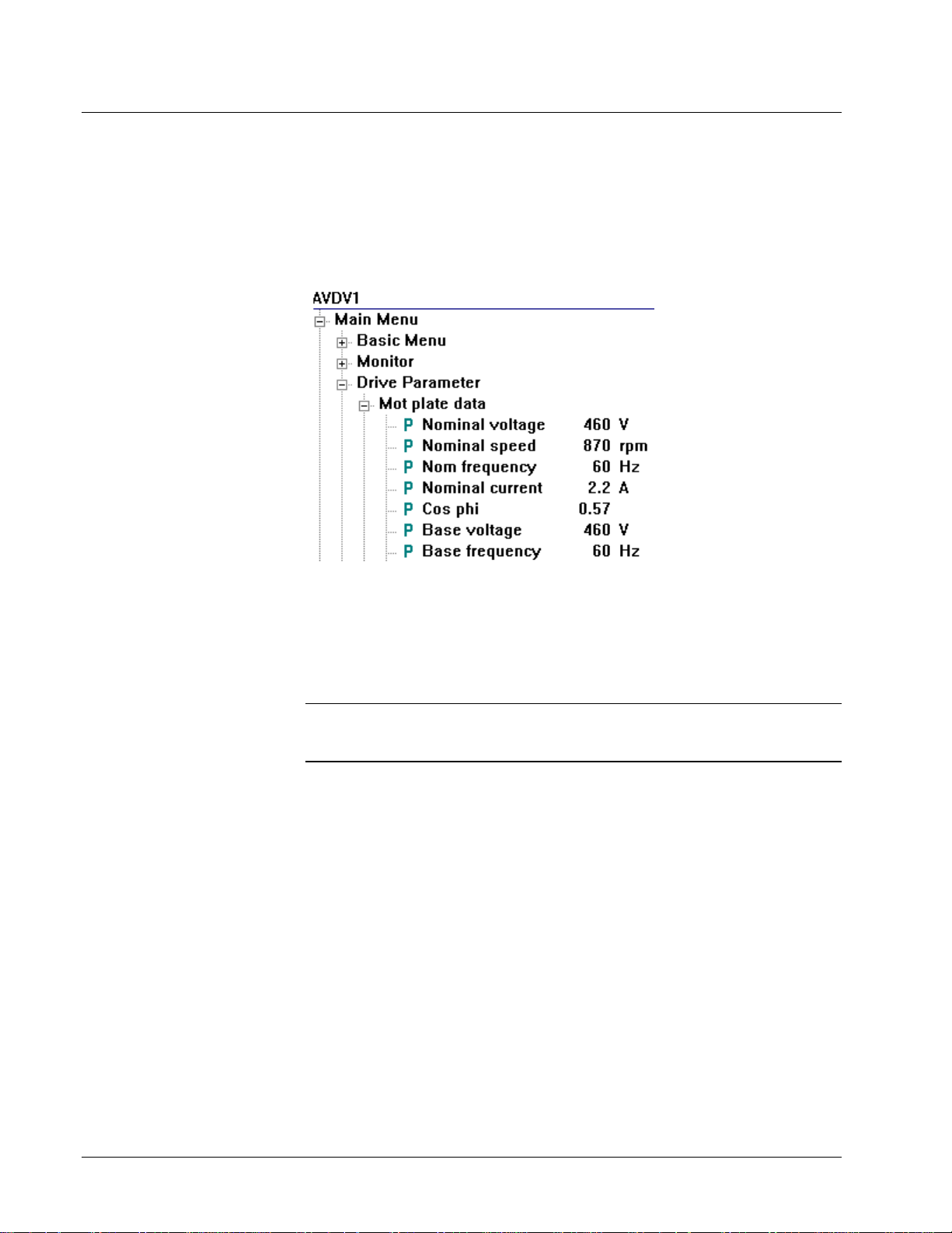
Once a new drive is created (or a file is opened), the Outline View displays the drive
name and two items; Main Menu and Diagram.
The default device name is
(where additional new devices are
incremented by one). This name
should be modified to more
accurately refer to the drive being
configured. The name is limited to
five characters
GEH-6405A Toolbox for an AVDV Series Drive Chapter 4 Configuring an AVDV Series Drive • 4-5
AVDV1
Page 36
The default device name is
AVDV1.
drive is incremented by one
number. If desired, edit the
name to more accurately
refer to the drive being
configured. Enter up to five
characters.
Each additional new
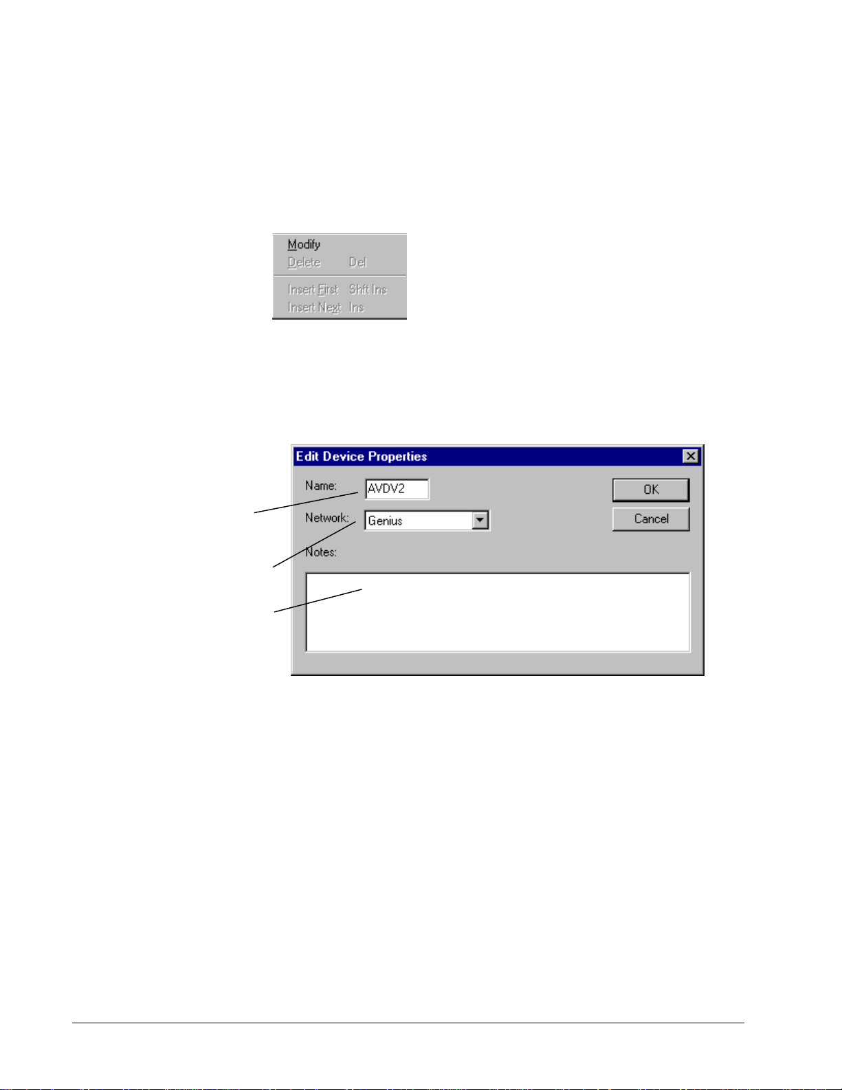
À To modify the drive
1. Click on the drive name to highlight it.
2. From the Edit menu, choose Modify.
– Or –
Use the right mouse button to click on the drive name and choose Edit from the
following pop-up dialog box.
The Edit AVDV Device Properties dialog box displays and allows you to edit
drive properties described in the next section, Modify Drive Properties.
Modify Drive Properties
Select the active
communications network
from the drop-down box.
Enter a note to describe the
drive.
4-6 • Chapter 4 Configuring an AVDV Series Drive GEH-6405A Toolbox for an AVDV Series Drive
Page 37

Validating the Drive
Also, items in the hierarchy
that had problems during
validation will display red
after the validation.
Or click
Each wizard dialog box
contains a Help button.
Each configuration depends
on application requirements.
For more information,
contact Product Service
Engineering at
+ 1 540 387 7597 or Fax at
+ 1 540 387 8606
(replace + with the
international access code).
Validation checks for errors that might prevent successful operation of the drive. If
the configuration needs to be validated, items in the Outline View displays in red.
Note In most cases, the configuration is automatically validated.
À To validate the drive configuration
w From the Drive menu, choose Validate.
The validation results display in the Log View at the bottom of the toolbox Work
Area screen.
Entering Job Specific Information
Once a new drive has been created and the properties are modified, you must enter
job specific data, such as motor hp, motor amps, and motor speed . This information
can be entered in a new configuration using the menus or the Offline Commissioning
Wizards (refer to the section, Wizards). A wizard is an interactive Help utility that
guides the user through each step of a particular task, such as drive commissioning.
À To configure the drive offline
1. From the Edit menu, choose Wizards.
2. Choose the Offline Basic Commissioning Wizard.
Note
Entering the Offline Basic Commissioning wizard information and
performing the applicable tune ups should be sufficient to configure the drive for
basic operation.
GEH-6405A Toolbox for an AVDV Series Drive Chapter 4 Configuring an AVDV Series Drive • 4-7
Page 38
Working with Files and Menus
An AVDV Series drive is configured using different types of files, which are
described in the following sections. Menu commands are also described.
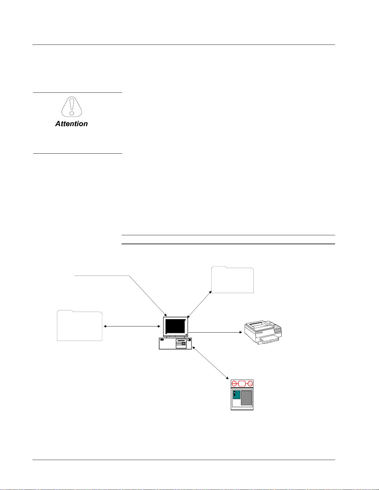
File Types
The configuration files generate output that can be downloaded to the drive.
Configuration files include:
Drive configuration file (.acb) is a binary working file that contains an exact copy
Back up all files often to
avoid loss of data.
of the drive configuration used by the toolbox. Users generally work from drive
configuration files. When the file is saved, the prior .acb is renamed to Backup of
File. For example AV300.acb would have a backup file named Backup of
AV300.acb. To restore the backup copy, rename the file to a .acb file.
Tree files (.tre) are text files that contain config uration information for the drive
product. Some define the parameters, faults, menus, and other items that exist within
a particular drive. Others store configurations for transport between different drives,
and possibly different versions of the toolbox.
Diagram files (.wmf) are drawing files that contain the toolbox block diagrams.
Help files (.hlp) provide product specific help from within the toolbox.
Project files (.prj) are text files that hold some drive confi guration information.
They are used, in conjunction with other tree files, to transport configurations across
versions of drive products, and possibly different versions of the toolbox.
Note
Pattern configuration files, such
as .tre, .wmf, .hlp, and such.
Create/New
hardware,
library, and
function .tre files
Export/Import
The .tre and .prj files are not normally used by users.
Programmer Workstation
*.acb file
Save
Documentation
+
AC
-
Windows NT or
Windows 95
running toolbox
AVDV Series Drive
Open
Print
Upload/Download
parameters
4-8 • Chapter 4 Configuring an AVDV Series Drive GEH-6405A Toolbox for an AVDV Series Drive
Page 39

Opening and Closing Files
Opening an drive configuration file (.acb) reads a previously saved drive
configuration into the toolbo x.
À To open a file
Or choose the
button.
Check the Release Notes
located in the toolbox Help
menu under About Toolbox.
Or choose the Save
button.
Open
1. From the File menu, choose Open. The Open dialog box displays.
2. Choose the file name and click OK.
Note
If an older version toolbox is used to open a drive configuration file (.acb) that
was saved with a newer ve rsion, a Warning box is displayed. Either install the
version of toolbox the drive con figuration file (.acb) was saved with (listed in the
Warning box) or consult the toolbox Release Notes to see if they are compatible.
À To close a file
w From the File menu, choose Close.
Closing a file removes the configuration from the toolbox. If the configuration has
not been saved, a dialog box displays and asks if the configuration should be saved.
Saving Files
Saving a file writes the entire contents of the configuration to a drive con figuration
file (.acb). The prior drive configuration file (.acb) is renamed to a Backup of .icb
file and used as a backup file.
À To save a file
1. From the File menu, choose Save. The Save As dialog box displays.
2. Enter the file name and click OK. (Once a configuration has been saved, the
Save button saves the new file without asking for a file name.)
Tip
¬ The Save button also indicates that a change was made to the configuration
by highlighting (red) and becoming enabled. If the computer or toolbox fails when
the button is red, all changes since the last save is lost, so save files often.
GEH-6405A Toolbox for an AVDV Series Drive Chapter 4 Configuring an AVDV Series Drive • 4-9
Page 40
Refer to Chapter 3, Using the
Toolbox.
Click
Yes
to upgrade
the drive.
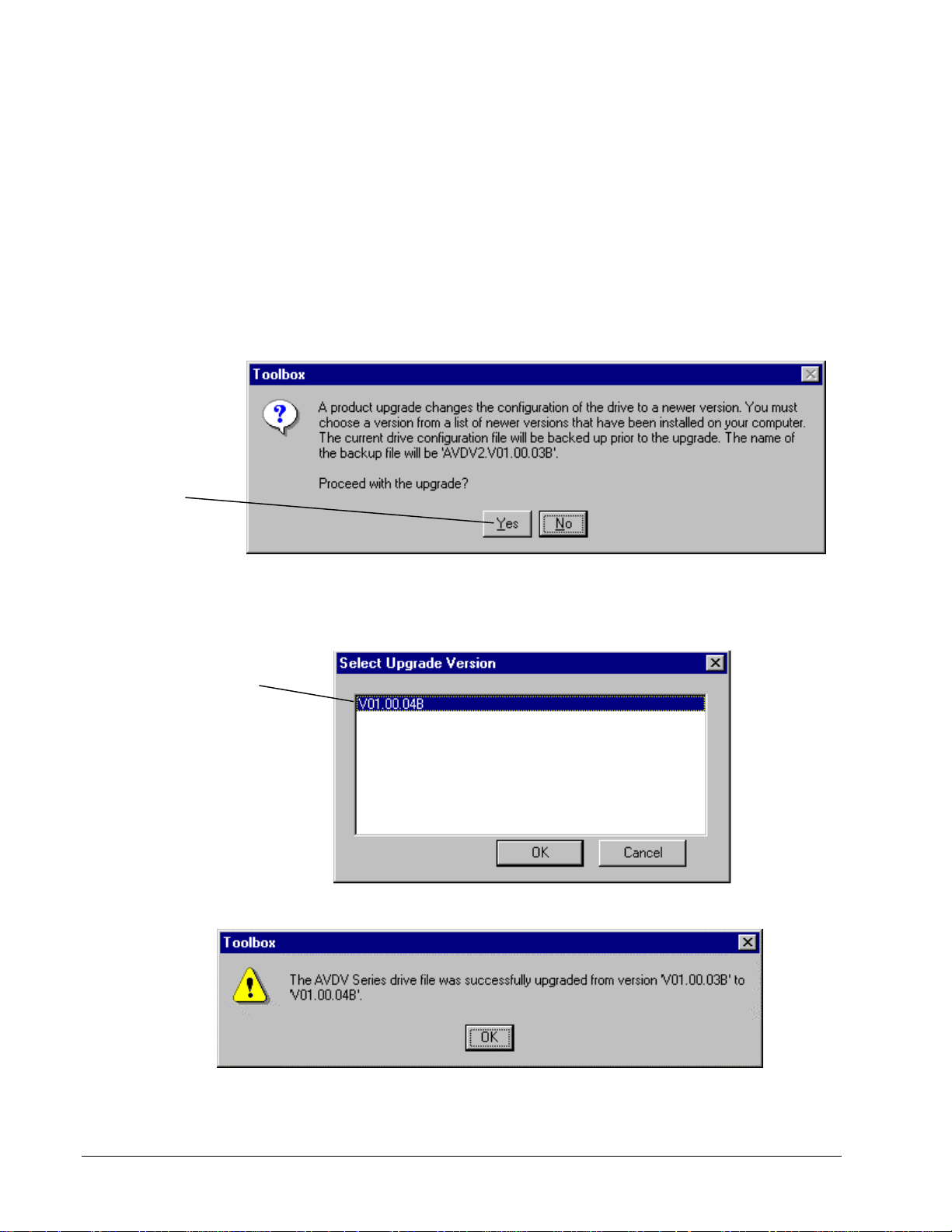
Upgrading a Configuration
The upgrade command adds the required functions of a newer version of the product
to the current drive configuration file. For example, the current drive configuration
file (.acb) is version V01.00.03B. The application req uires the functions of version
V01.00.04B. Upgrade the drive configuration file as follows:
À To upgrade a file
1. Make sure the new required version is installed (refer to Chapter 3).
2. From the current drive configuration file, such as version V01.00.03B described
above, choose the File menu and choose Upgrade. The following message box
prompts to proceed you with the upgrade.
Select the required
version.
Select Upgrade Version
If you select to upgrade the drive, the Select Upgrade Version dialog box
displays all newer installed versions.
The following message displays.
4-10 • Chapter 4 Configuring an AVDV Series Drive GEH-6405A Toolbox for an AVDV Series Drive
Page 41
Exporting Configuration Files
The .tre files can be exported
selectively or for an entire
drive.
The parameter values contained in a drive configuration file (.acb) can be exported
in a .tre file format. Exporting drive parameters allo ws setting s among drives to be
shared. Refer to the next section Exporting/Opening.
À To export parameter values
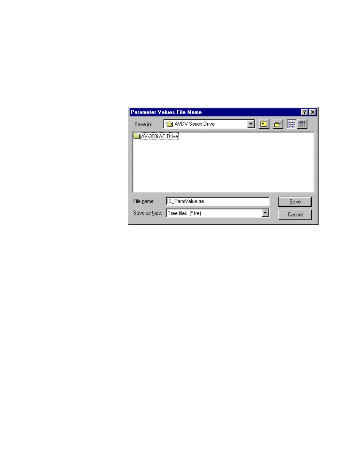
1. From the File menu, choose Export, then choose Parameter Values. The
Parameter Value File Name dialog box displays.
2. Confirm the current project directory/file name or choose a new directory. Click
Save. The file is saved as a .tre file.
GEH-6405A Toolbox for an AVDV Series Drive Chapter 4 Configuring an AVDV Series Drive • 4-11
Page 42

Project files allow the user to
export and import a drive
configuration without having
to know about all the files it
contains.
Exporting/Opening Project Files
This option is normally not required, but is
provided if a newer version of the t oo lbox makes a
change to the format of the drive configuration file
(.acb) that is not backward compatible.
Normally, newer versions of the toolbox can load drive configuration files created
by older versions. However, if a major change in functionality of the toolbox occurs,
the toolbox may not be able to load the drive configuration file. In this case, it is
necessary to first export the drive configuration file to a project (.prj) file and then
import it into the new version of the toolb ox. A project file is a text file, which
contains the names of all .tre files in a configuration. Project files save the drive
configuration in a form that can be loaded by all newer versions of the toolbox.
À To create a project file
1. From the Outline View, click on the drive name.
2. From the File menu, choose Export and choose All. All .tre files and the .prj
file is exported.
Once a project file exists, it can be used to create a drive configuration file (.acb).
From the file Open command, choose a .prj file. This creates an AVDV Series drive
and starts a series of file imports. The toolbox imports the files listed in the .prj file,
including the parameter values file.
4-12 • Chapter 4 Configuring an AVDV Series Drive GEH-6405A Toolbox for an AVDV Series Drive
Page 43
Menu Commands
File Menu
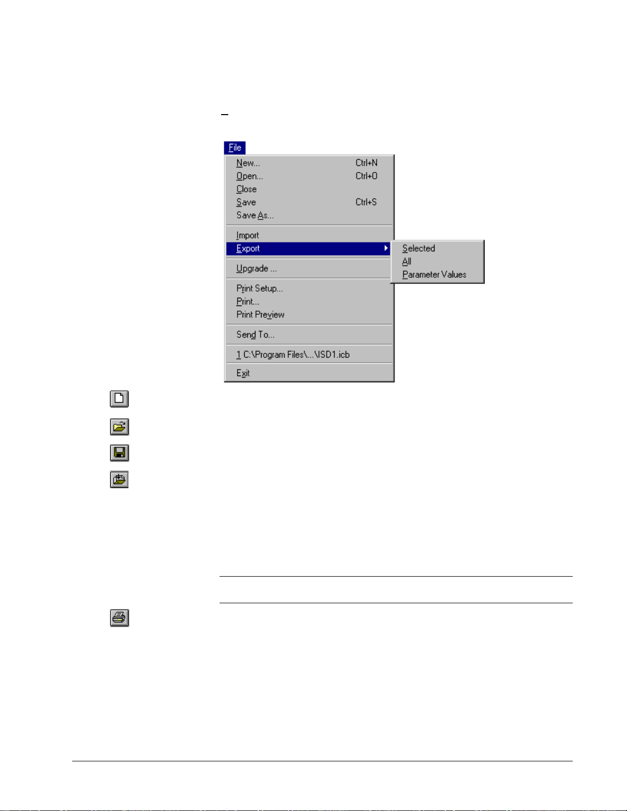
The File menu allows you to perform file operations with the following commands:
Or click
Or click
Or click
Or click
Or click
New creates a new drive configuration file.
Open loads an existing drive configuration file into the toolbox.
Close exits an existing drive co nfiguration.
Save/Save As saves an opened d rive configuration file to a specified na me.
Import retrieves values from the specified file. The values in the current
configuration are replaced with the imported values.
Export sends specified items (such as parameters and files) to a designated file.
Upgrade automatically makes the required changes to upgrade an older product
version to a newer version.
Print Setup allows the user to choose a printer and printer connection.
Tip
¬ The block diagram is designed to print best in Landscape Orientation. Refer
to the section, Block Diagrams/Printing Diagrams.
Print provides a paper (hard) copy of a specified file or page.
Print Preview displays the page as it would be printed.
Mail To opens email and provides a copy of the currently opened file to send (you
must have Window messaging, such as Exchange).
File 1, 2, 3... lists and opens the most recently used files.
Exit closes the toolbox.
GEH-6405A Toolbox for an AVDV Series Drive Chapter 4 Configuring an AVDV Series Drive • 4-13
Page 44

Or click
Edit Menu
The Edit menu allows you to edit items with the following commands:
Modify allows you to edit the highlighted ite m.
Wizards allow you to choose from a list of wizards used for drive configurations
commissioning, tests, and tune-ups.
Or click
Bookmarks enable you to mark major items in the O utline View and then return to
them easily using the menu command Goto Next Bookmark.
4-14 • Chapter 4 Configuring an AVDV Series Drive GEH-6405A Toolbox for an AVDV Series Drive
Page 45

View Menu
ä
Some of these commands can
be toggled on and off. A check
mark (
command name when the
feature is on and it will
display in the toolbox.
Or click
) displays next to the
The View menu allows you to manage the drive with the following commands:
Toolbar displays or hides the Toolbar.
Status Bar displays or hides the Status bar.
Tracking toggles the tracking feature of the Summary View on and off.
Close Outline reduces the hierarchy list of items displa ying in the Outline View to
just the drive level.
Or click
Or click
Or click
i
Or click
Or click
The list can also be displayed
by double-clicking on the
status bar (yellow indicates
an alarm or red indicates a
fault).
Detached Summary creates a detached window of the Diagram View.
Zoom In enlarges the view of the block diagram area (Summary View).
Zoom Out reduces the view of the block diagram area (Summary View).
Finder starts the Finder view to search text.
Trend Recorder is a separate window in the toolbox (refer to the manual, GEH-
6408). Use this feature to find items, such as text and variables within a
configuration.
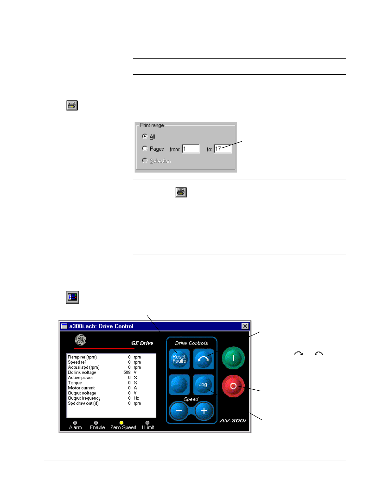
Drive Control starts the Drive Control view used to start and stop the drive. It also
provides specific information, such as motor speed, volts, amps and power.
Active Faults displays a list of all active faults and alarms. Each fault is time
stamped so that the order of events can be determined.
Fault History displays a list of faults that are saved in the drive.
Reports contain the following options:
Compare Parameters Values produces a report that shows all parameters whose
values in the toolbox are not the same as in the drive.
Parameter Values displays all parameters and their values in a menu hierarchical
structure.
Change History produces a report of changes made to the drive configuration file.
GEH-6405A Toolbox for an AVDV Series Drive Chapter 4 Configuring an AVDV Series Drive • 4-15
Page 46

Device Menu
The Device menu allows you to manage the drive with the following commands:
Or click
Or click
Or click
Or click
Validate makes certain that drive configuration does not contain errors.
Online/offline toggles to start or end communications between the toolbox and the
current drive.
Download Parameter Values to Drive sends the values of all the parameters
from the loaded drive configuration files to the current drive.
Download Parameters (include Service Parameters) sends the current
parameter set from the loaded drive configuration files including the factory Service
parameters.
Upload Parameter Values from Drive reads all the parameter values from the
current drive and provides the option of replacing the values in the currently loaded
drive configuration file in the toolbox.
Save Parame ters saves the current active set of parameter values in the drive to
permanent storage
Reset Faults resets all faults that are currently active in the drive.
Download Network Configuration downloads the active network configuration.
Upload Network Configuration uploads the active network configuration.
Load Default Values loads the factory defaults in the drive and the currently
loaded drive configuration file in the toolbox. This selection requires the drive to be
online. The drive loads factory settings only when the drive is disabled.
4-16 • Chapter 4 Configuring an AVDV Series Drive GEH-6405A Toolbox for an AVDV Series Drive
Page 47

Take Motor Parameters corresponds to the Take Motor par command in the
drive (keypad). This command must be issued after entering values into the “Mot
plate data” submenu in order to validate them and compute estimates for the
parameters in the “Motor parameter” submenu. Previous values in the “ Motor
Parameter” submenu are overwritten. This menu item ma y not be enabled for all
drive types.
Load Motor Parameters corresponds to the Load Motor par command in the
drive (keypad). Choose 400 V or 460 V parameters.
Copy Motor Setup ( Setup 0, Setup 1) copies the current motor parameters to
the alternate storage provided by either Setup 0 or Setup 1.
Motor Selection ( Setup 0, Setup 1) causes the alternate motor parameter
values in either Setup 0 or Setup 1 to be copied to the active motor para meters.
Self-tune activates the self-tune process where the drive and the motor perform
predefined tests to determine the best running conditions for the system.
Options Menu
The Options menu allows you to manage general options for too l box operation.
Settings allow you to set general toolbox options.
Privilege sets the privilege level for a session.
Passwords set the password for a privilege level.
Logout User closes the current user from the current se ssion and sets the privilege
level back to 0.
GEH-6405A Toolbox for an AVDV Series Drive Chapter 4 Configuring an AVDV Series Drive • 4-17
Page 48
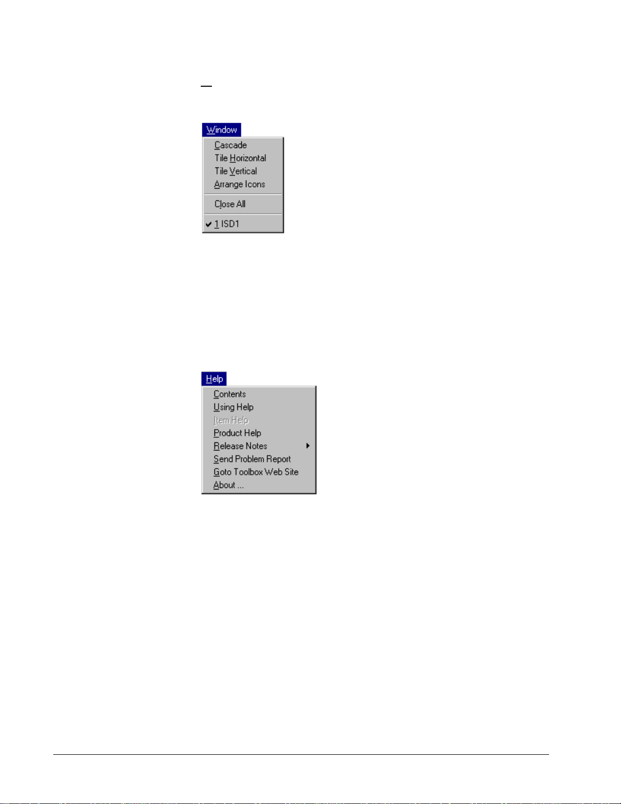
Window Menu
The Window menu arranges multiple views of open documents in the dr ive window
with the following commands:
Cascade arranges the windows in an overlapped style.
Tile Horizontal arranges the windows ho rizontally in non-overlapped tiles.
Tile Vertical arranges the windows vertically in non-overlapped tiles.
Arrange Icons arrange the icons of closed windows.
Close All closes all open windows.
Help Menu
The Help menu has the following command s:
Contents displays Help files for the toolbox. It also contains the Find tab with a
work list to search for specific topics.
Using Help displays general instructions on how to use Help.
Item Help displays help for the item selected in the Outline View.
Product Help displays the Help file for the currently loaded pattern. The file
contains help on parameters, faults, diagrams, and wizards.
Release Notes
Send Problem Report
Goto Toolbox Web Site
About … displays the version number of the toolbox.
4-18 • Chapter 4 Configuring an AVDV Series Drive GEH-6405A Toolbox for an AVDV Series Drive
Page 49
Concepts
The drive name can
be modified.
The following section defines items and fea tures used when configur ing an AVDV
Series drive. When a drive is created, the Work Area displays as follows:
Main Menu contains
the configurable
items.
Click here to display a
drawing of the block diagram
and signal flow.
Parameters allow you to configure the drive behavior. Each parameter has a name
with up to 20-characters, which identifies it and helps to convey its use. A parameter
also can have units, such as RPM, displayed with the toolbox and keypad. The unit
field is limited to five characters. Each parameter contains a value, which can be a
number or a setting. The value is adjusted in order to modify the drive behavior.
Some basic parameters along with their associated units are: Motor rated current
(Amps), Motor rated freq (Hz), Motor rated vo ltage (Volts), and Regulator type.
Parameters can be set and modified from the Outline View under the items Main
Menu or Diagram, or from a Wizard or the keypad.
Variables, similar to parameters, have a 20-character name and a 5-character unit
field. However, unlike parameters, the user can not change variables. They are
changed by the drive as a result of the execution of the pattern within it. For
example, the variable Speed feedback (RPM ) gets updated on a continuous basis and
represents the drives actual speed.
Diagrams provide an overall picture of signal flow, sequencing and regulator control
in the drive. While communicating with the dr ive, the diagrams display drive
variables and their real time values. Contact and coil states are also indicated.
Certain drive parameters can be modified from this view (refer to the section, Block
Diagrams).
GEH-6405A Toolbox for an AVDV Series Drive Chapter 4 Configuring an AVDV Series Drive • 4-19
Page 50
Configuration
Parameters
For detailed information
about a parameter, click on
the parameter (to highlight it)
and press F1.
Use the Finder to easily
locate a specific parameter.
The drive contains a set of parameters whose values, together with the pattern and
version, define the drive behavior. In the Outline View of the toolbox, parameters
display as follows:
À To modify a parameter
1. From the Outline View, click on the parameter to modify.
2. Choose the Edit menu and choose Modify.
Or, double-click on the parameter. The Edit Parameter dialog box displays
(refer to the next section).
Tip ¬ If you know the name of the parameter (or partial name) choose the Finder
and enter the name in the text box. Click Find and a list of parameters and variables
display. Double-click on the parameter/variable to modify.
4-20 • Chapter 4 Configuring an AVDV Series Drive GEH-6405A Toolbox for an AVDV Series Drive
Page 51

Edit Parameter
Enter a new value (within the range) or choose a value from the dropdown menu. Then, click
Send to Drive
Note
for the value to take effect.
When a parameter value is edited, you must click Send To Drive for the value
to take effect. Also, remember to permanently save the parameter, select Device
menu and Save Parameters.
The new value displays under
the field
Drive Value
This function is currently
not available.
Click to display the
detailed Help for this
parameter.
Click to send the new
value to the drive.
This button may not be
enabled for all parameters.
It allows you to change the
display units. (This button
only effects the displayed
values and not the drive
control.)
Enter a note for this
parameter, if desired.
.
GEH-6405A Toolbox for an AVDV Series Drive Chapter 4 Configuring an AVDV Series Drive • 4-21
Page 52
This option changes the
names used on the
diagrams and Outline View
to internal names used
mainly by firmware
developers.
be checked.
It should not
Toolbox/Drive Communications
The toolbox can communicate with the drive through an RS-232C/RS-485 serial port
connection. However, only one drive at a time can be selected to go online
(communicate). Refer to the next section, Connecting to an AVDV Series Drive.
The serial port connection settings used by the toolbox can be defined and modified.
These settings are saved and used by the toolbox for every connection to a drive
whose drive configuration file is set to communicate serially.
À To modify the communications setting
1. From the Options menu, choose Settings.
2. Click on the tab, AVDV Series Drive.
3. Modify the Serial Port Communications settings, as desired.
Settings
Note
Depending on the products insta lled, all of the following tabs may not be
available.
Click on the drop-down box to choose the
communication port.
4-22 • Chapter 4 Configuring an AVDV Series Drive GEH-6405A Toolbox for an AVDV Series Drive
Page 53
Connecting to an AVDV Series Drive
Choose the Window menu to
view multiple drive windows,
when drives are offline.
Or click
When the drive first goes
online or requires
updating, adjust the range
of addresses to be
scanned on the RS485
link.
Click the
button. A list of drives
displays in the list box.
Start Scanning
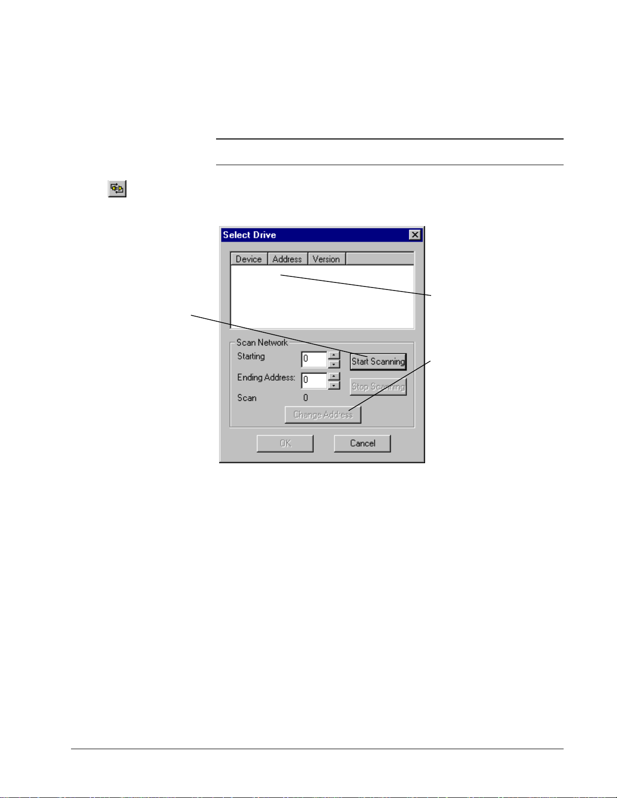
Multiple drives can be wired on the same network through an RS485 link. Each
drive on the network has a unique name and address. The drive displays in the Select
Drive dialog box when you select to go online.
Note
Only one drive at a time can be selected to go online. To select a different
drive, you must choose to go offline.
À To connect to an AVDV Series drive
w From the Device menu, choose Online. The Select Drive dialog box displays
(see the next section, Select Drive).
AV-3000i 0
Select the drive to
OK
connect to. Click
Or
, double-click on the
drive name.
To change the device’s
multidrop system, click
on the desired drive and
Change Address
click
Select the new address.
.
.
GEH-6405A Toolbox for an AVDV Series Drive Chapter 4 Configuring an AVDV Series Drive • 4-23
Page 54
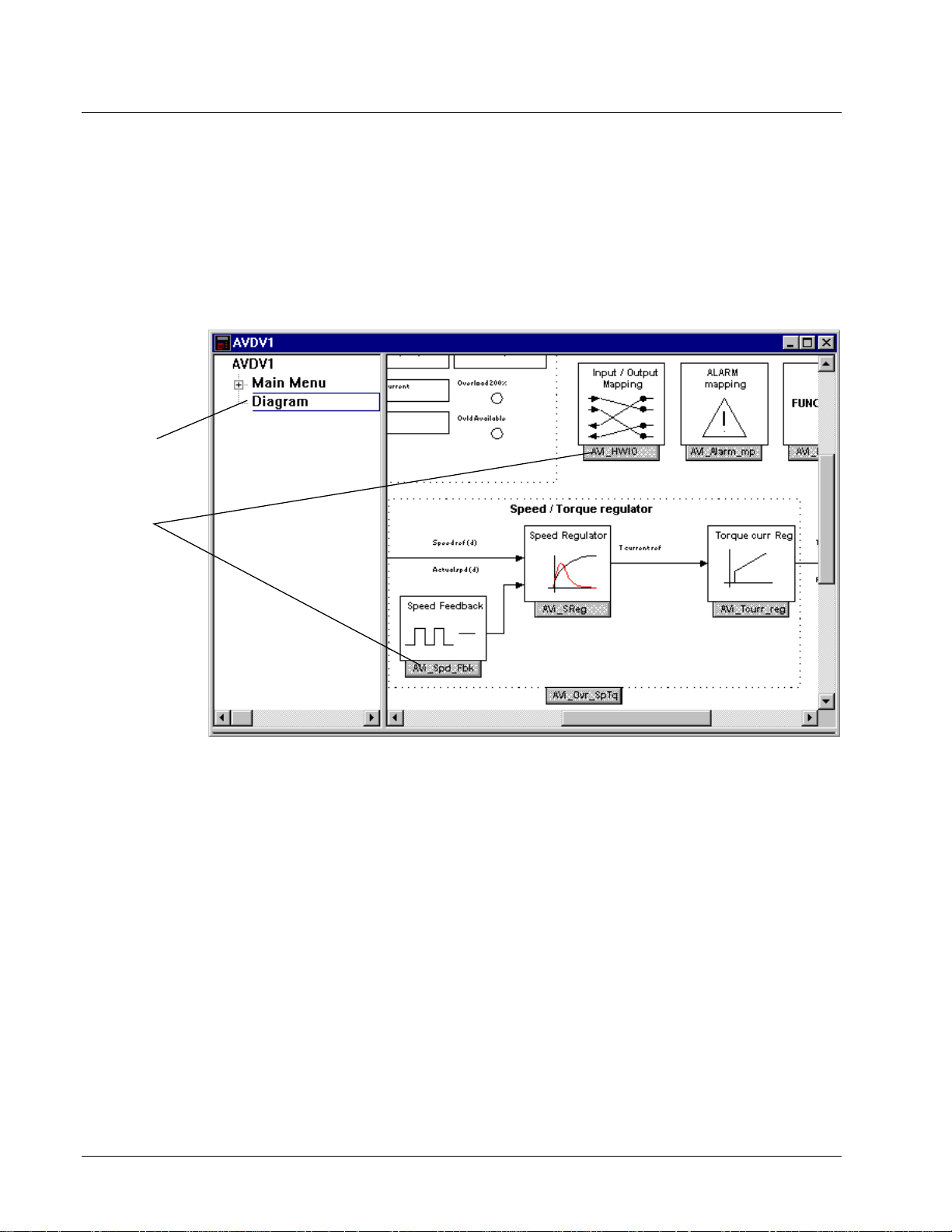
Block Diagram
In landscape, the long edge of
the paper is horizontal.
Click Diagram to
view drive block
diagrams.
Click the various
link buttons in the
Overview diagram
to view details of
the block.
Use the scroll bars
to view the entire
Overview diagram.
Use the Print
command to print
the diagram.
Diagrams provide an overall picture of signal flow, sequencing and regulator
control in the drive. While communicating with the drive, the diagrams display drive
variables and their real time values. Contact and coil states are also indicated.
Certain drive parameters can be modified from this view
À To access diagrams
w From the Outline View, click on the item Diagram. The Overview diagram
displays in the Summary View , as follows:
4-24 • Chapter 4 Configuring an AVDV Series Drive GEH-6405A Toolbox for an AVDV Series Drive
Page 55
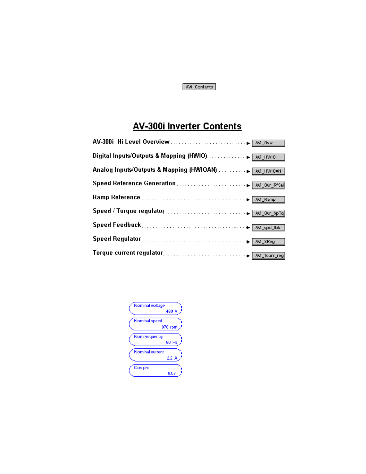
Links to Other Pages
Diagram provides links to other pages, which contain information on drive functions.
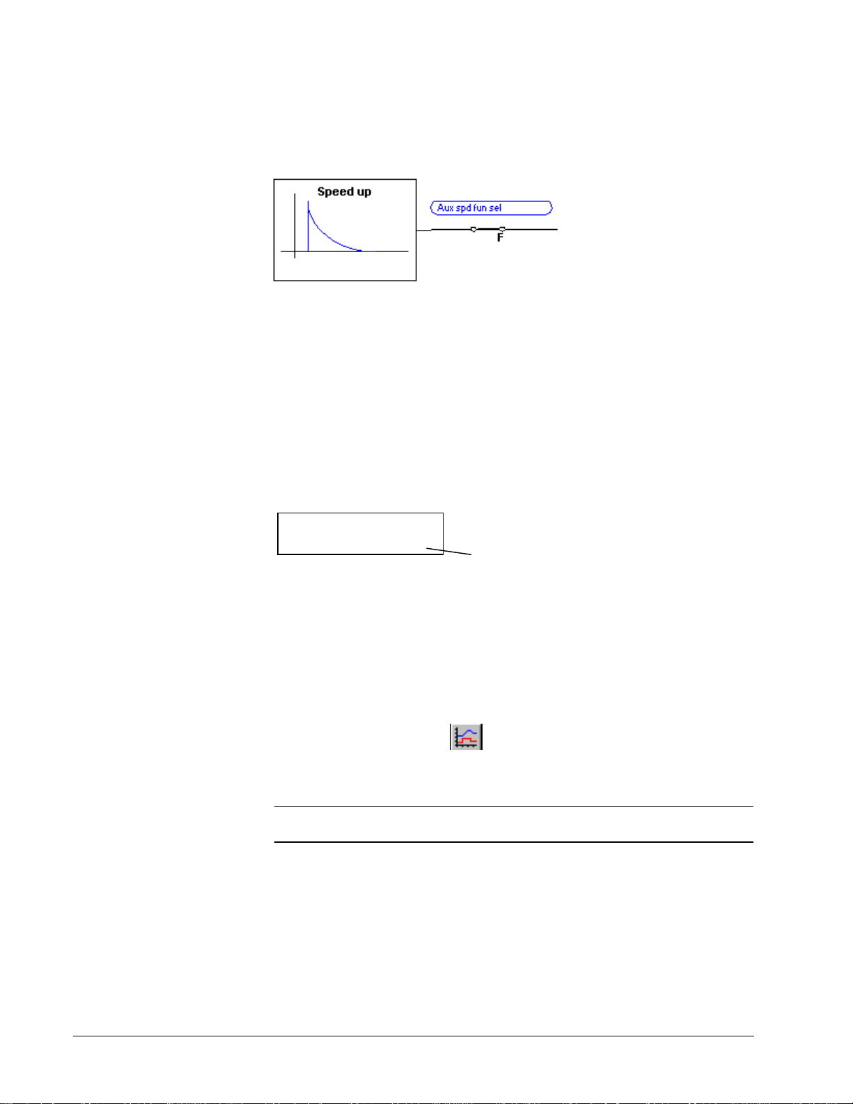
À To access diagram links
1. From the Summary View, place the mouse pointer on a link button in the
diagram, such as
2. When the pointer turns into a hand, click on the link button. Another diagram
displays with more details and links. An Index is provided, as sho wn below.
.
Modify Parameters from Diagram
Parameters can be modified from the Diagram. In the Diagram, the toolbox displays
parameter names in the color blue as follows:
À To modify a parameter
w From the block diagram, move the cursor over the parameter until it changes
into a hand. Click on the parameter. The Edit Parameter dialog box displays
(refer to the section, Parameter Settings).
GEH-6405A Toolbox for an AVDV Series Drive Chapter 4 Configuring an AVDV Series Drive • 4-25
Page 56
Parameter Jumpers
In the Overview diagrams, parameter jumpers show how different paths of the block
diagram are connected together.
Live Data Display
If the toolbox is connected to the drive, all variables on the diagram display live
values. On the Status bar, the scan rate shows the time it takes to update all the
variables on the currently selected page.
Variables
Green values are valid
numbers received from the
drive.
Variables in the block
diagram can be copied to the
Trend Recorder using the
drag-and-drop feature.
Choose the Windows menu
and Tile Horizontal or Tile
Vertical.
Variables can be monitored by the toolbox. Live values display in the color green.
Actual spd (rpm)
422 rpm
Live value
Drag-and-Drop Variables
À To drag-and-drop a variable in the Trend Recorder.
1. From the toolbox Outline View, click Diagram to display the Overview
diagram in the Summary View.
2. Click the link buttons to locate the desired variable(s). The Diagram (Summary
View) becomes full screen.
3. From the button bar, click
4. Resize and move the Trend Recorder window so that it and the block diagram
can be viewed (using regular Windows features).
Tip ¬
choose
To view both the toolbox and the Trend Recorder, from the Window menu,
Tile Horizontal
or
Tile Vertical
to open the Trend Recorder.
and adjust the size of the windows.
5. From the Diagram, place the mouse pointer over the desired variable.
6. When the pointer changes to a hand, press and hold the left mouse button. The
pointer changes to the drag-and-drop cursor.
7. Continue to hold the left mo use button down and drag to the Trend Recorder
window. At the Trend Recorder, the cursor changes to the drop pointer.
8. Release the mouse button and the variable will drop in the Trend Recorder.
4-26 • Chapter 4 Configuring an AVDV Series Drive GEH-6405A Toolbox for an AVDV Series Drive
Page 57
Printing Diagrams
with an icon or
Or click
Drive Controls
Tip ¬
the
The block diagram(s) is designed to print in Landscape Orientation. From
File
menu, choose
Print Setup
and click the option
Landscape
.
À To print block diagrams
1. From the Outline View, click the item Diagram.
2. From the File menu, choose Print. The Print dialog box displays.
3. Choose the number of copies to print and the page(s).
This field shows that there are 17
diagrams in this device.
Click OK to print all the diagrams
or enter the page number(s) to
print.
Tip
¬ To print a single block diagram, link to that page, so that it displays on the
screen and click . Choose OK. Live data can be printed, if the drive is online.
The Drive Controls command enables you to operate the drive from the toolbox, as
though you were operating it directly from the keypad located on the cabinet door.
The variables that display are the same as those that display on the keypad.
Or click .
Note The actual Drive Controls (keypad) can vary depending on the product that
connected to the toolbox.
À To display the Drive Control view
w From the View menu, choose Drive Control. The Drive Control view
displays.
Click here to reset faults.
Click here to toggle the
direction of the drive
(reverse resquest). The
selected direction is show n
Click here to Run the
drive in the selected
direction.*
Stop command can be
used in Local or Remote
mode.
Click here to Jog the drive
in the selected direction.*
GEH-6405A Toolbox for an AVDV Series Drive Chapter 4 Configuring an AVDV Series Drive • 4-27
Page 58

Wizards
A wizard is an interactive
Help utility that guides the
user through each step of a
particular task, such as Drive
Commissioning.
The Wizard list can vary with
each product, but there is
always a Offline Basic
Commissioning Wizard.
The Offline Basic
Commissioning Wizard
or the Offline Advanced
Commissioning Wizard
should be the first step
when setting up a new
drive.
The AVDV Series drive contains wizards that guide you through the setup of a
drive. Wizards display a series of dialog boxes that prompt the user for drive
configuration information. This information is also used as a basis to perform
additional tests and tune-ups on t he drive.
Note
The Offline Basic Commissioning Wizard or the Offline Advanced
Commissioning Wizard should be the first step when setting up a new drive.
À To perform a wizard
w From the Edit menu, choose Wizards, or click
wizards displays.
. The following list of
Choose Wizard
The following dialog box is an example of the Offline Basic Commissioning
Wizard. Enter a value in each field, unless you are instructed otherwise.
Click here to obtain
interactive Help on
each field.
4-28 • Chapter 4 Configuring an AVDV Series Drive GEH-6405A Toolbox for an AVDV Series Drive
Page 59

Uploading Parameters
Parameter values can be uploaded from the drive to the toolbox. This is necessary
after a self-tune or when values are modified using the keypad. The toolbox reads all
the values from the drive and compares them to the values in the toolbox. A list of
differences is generated and the user is allowed to select the parameter values to
upload to the toolbox configuration.
À To upload parameters
w From the Device menu, choose Upload Parameter Values from the Drive, or
click
Tip
À Remember to save the toolbox configuration file. From the File menu,
choose Save or click .
.
GEH-6405A Toolbox for an AVDV Series Drive Chapter 4 Configuring an AVDV Series Drive • 4-29
Page 60

Fault Display
The Status bar, located at the bottom of the
screen, indicates that a fault has occurred.
The toolbox can display two types of fault lists.
•
Fault History list displays a list of faults that ha ve cumulated since power was
applied to the drive (see the section, Fault History).
•
Active Fault list displays faults that are currently active in the drive (see the
section, Active Fault).
The fault displays in red.
Double-click on the fault to
display the Active Fault list.
Active Fault
À To display the Active Fault list
w From the View menu, choose Active Faults.
– Or –
w Double-click on the Alarm on the Status bar (see previous section, Fault
Display). The following dialog box displays.
Click here to reset the
fault list.
Check here to display a
description of the selected fault.
4-30 • Chapter 4 Configuring an AVDV Series Drive GEH-6405A Toolbox for an AVDV Series Drive
Page 61

This list is stored
in the drive.
The fault time
displays a list of
faults that have
cumulated since
power was applied
to the drive
The most recent
fault appears at
the top of the list.
Click here to clear
the fault list.
Click
Help
for a description of the selected fault.
Fault History
À To display the Fault History List
w From the View menu, choose Fault History. The following dialog displays.
Self-tune
For more information, refer
to GEI-100331, AV-300
Adjustable Speed Drives;
GEI-100360, AV-300I
Adjustable Speed Drives and
GEI-100332, DV-300
Adjustable Speed Drives.
Self-tune is a process where the drive and the motor perform predefined tests to
determine the best running conditions for the system.
À To self-tune a drive
1. Create or open an AVDV Series drive
2. From the Device menu, choose Online or click
.
3. From the Device menu, choose Self-tune. The Self-tuning dialog box display
(see the next section, Self-tuning the Drive). For DV-300 drives, refer to the
section DV-300 Current Tune.
Self-tune the Drive
The parameter, Main Commands (that determines whether the drive is controlled by
hard wired terminal inputs or digitally), must be set to Digital or the toolbox sends
the following prompt:
Choose Yes to continue and the Self-tune dialog box displays.
GEH-6405A Toolbox for an AVDV Series Drive Chapter 4 Configuring an AVDV Series Drive • 4-31
Page 62

Choose the desired self-
and copies them to the
from the drop-down
Click to Start the
self-tune test in
Click to Stop the self-tune
in process.
Click here after the self-
has completed.
This command takes the
Computed Values
created from the self-
list
Current Values
used by the current
Close
Click
process (see note
Note:
saved to non-volatile
From the
choose
The state of the selfdisplays here.
Additional messages may display here as the self-tune
to end the
These values must
Device
Save Parameters
Click Start and the following caution displays. C lick Yes to contin ue.
list to be
menu,
.
4-32 • Chapter 4 Configuring an AVDV Series Drive GEH-6405A Toolbox for an AVDV Series Drive
Note When you close the Self-tune dialog box, the following caution displays if
your Main Commands setting was switched to Digital in the first step ab ove. Choose
OK to continue.
Page 63

Using the Finder
DV-300 Current Tune
Click to Start the selected
self-tune test in process.
Click to Stop the self-tune test
in process.
Click here after the self-tune
has completed.
This command takes the
Drive Values
copies them to current drive
configuration.
Close
Click
process (see note below).
The Finder is a separate window in the toolbox, which contains several useful find
tools. It can help you find items, such as text and variables from the different types
of drives.
listed and
to end the
Or click
À To use the Finder
1. From the View menu, choose Finder. The Finder window
.
2. Choose a target from the drop-down Target List. (All loaded targets are listed.
displays.
The default target is the current device.)
3. Choose a tab according to the type of search desired.
4. Enter each field of the tab (described in the next section).
5. Click
. Once the search completes, the Output View and Status bar
display the results.
Tip ¬
By default, the Finder closes when the Find button is clicked on or when you
click on any part of the screen outside the Finder Window. Click
Finder open
.
to keep the
GEH-6405A Toolbox for an AVDV Series Drive Chapter 4 Configuring an AVDV Series Drive • 4-33
Page 64
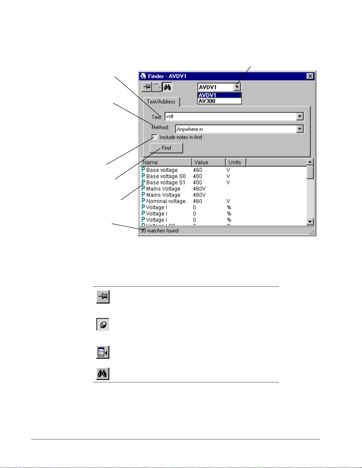
Finder Window
Enter the text to find. (wildcards such
as * and ? are not supported). the
drop-down list box allows you to
access previous finds.
Method allows you to qualify the find
by choosing one of the following from
the drop-down box:
Anywhere In
contain the find text anywhere within
their text.
Begins with
text begins with the find text.
Exact matches
exactly as the find text.
Click here to include all note
message boxes in the find.
Click the
find.
All text that is found displays in the
Output View
Status bar provides information about
the find operation.
matches items that
matches items whose
items whose text is
Find
button to start the
.
Choose a target from the drop-down Target List. (All loaded
targets are listed. The default target is the current device.)
The Finder target determines the drive and area of the search. When the Finder is
activated, it automatically chooses the current drive as the target and displays its
name in the Title bar. An AVDV Series drive target can find parameters and
variables.
Located below the Title bar is the toolbar, as described below:
Click To
Hold the Finder Window open. If this pushpin displays, the
Window closes when the area outside the Finder Window is
clicked. Click on the pushpin to keep the Finder on top of the
Device Window, even when you click outside the Finder Window.
Close the Finder Window. This pushpin displays when the
pushpin above is clicked on. The Finder Window remains opens
when the pushpin is in this position (even when working in
another window).
Goto an item in the Outline View. Highlight an item in the Output
View, then click this button to find it in the Outline View. Double-
click on an item to edit it.
Hide the tabs and make the Finder window display only the
Output View.
4-34 • Chapter 4 Configuring an AVDV Series Drive GEH-6405A Toolbox for an AVDV Series Drive
Page 65
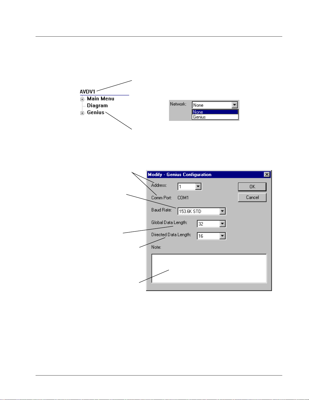
Genius Configuration
This section describes the
Horner Electric’s Genius
™
Serial Bus Interface (SB I) for
AVDV Series drives.
This is the address of the Genius board. This address must
be unique from other devices on the same Genius bus.
The
Comm Port
Settings
The
match the current setting of the other
Genius devices on the same bus.
and the tab
Baud Rate
is selected from the
of the Genius bus must
The Genius board configuration is separate from the drive configuration. The
following sections describe how to insert a Genius and set communication values.
To insert Genius, right-mouse click on the
Modify.
drop-down box.
Genius
. The
dialog box displays
Modify
AVDV Series
drive name and select
In the Properties dialog box, select Genius
from the
Genius is inserted.
Right- mouse click on
Genius Configuration
to edit communication values.
Options
.
Network
menu. Select
Select the amount of
transmitted continuously from the drive
on the Genius bus. The size can be from
0 to 32 words of data. The more data
selected here, the higher the impact on
the Genius bus scan time.
Select the amount of
is received continuously by the drive and
on the Genius bus. The size can be from
0 to 16 words of data. The more data
selected here, the higher the impact on
the Genius bus scan time.
Enter a note associated with the Genius
configuration.
Global Data
Directed Data
that is
that
GEH-6405A Toolbox for an AVDV Series Drive Chapter 4 Configuring an AVDV Series Drive • 4-35
Page 66
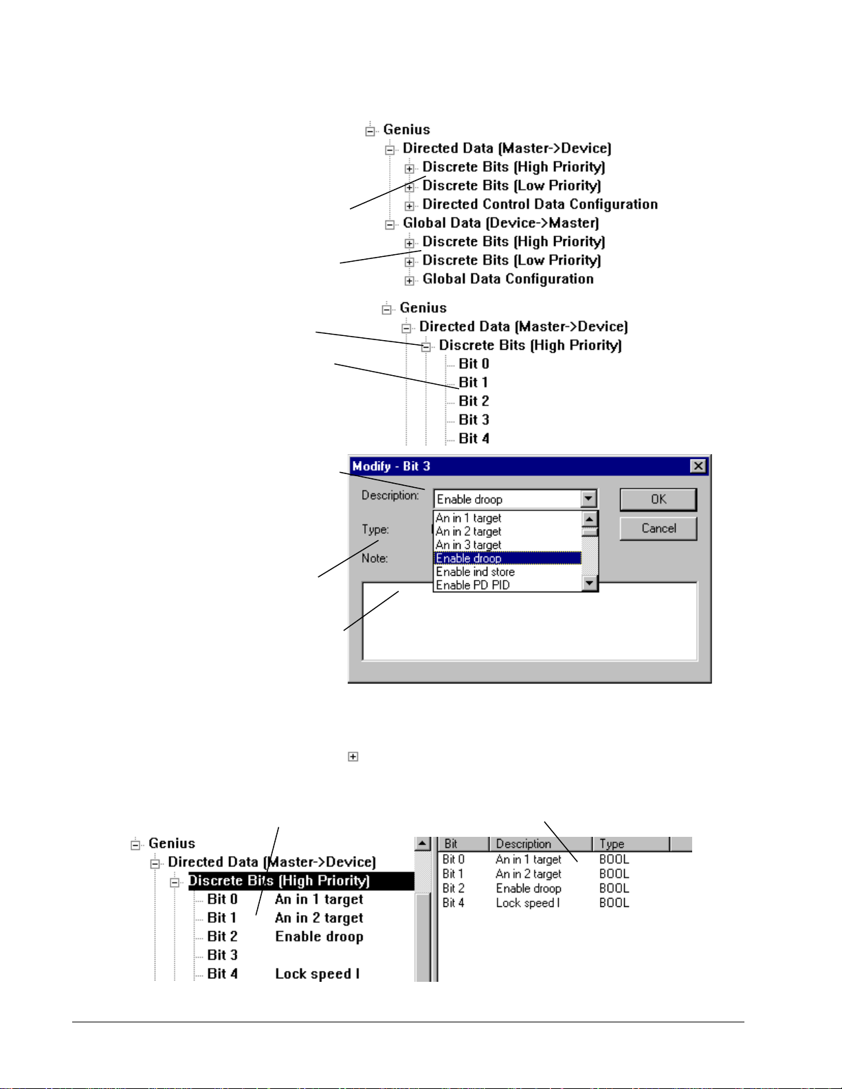
Discrete Bit Data
When the Genius item is
expanded, four types of
data
can be set:
Discrete bits passed from the
Genius to the drive.
Discrete bits passed from the
drive to the Genius.
discrete
Expand the
view all the bits.
Right-mouse click on the bit. The
Modify
Select a parameter or
variable for this bit.
view parameter and variable
numbers, from the
menu, select
the tab
then select
Names
4: Full Drive Access user.)
The
Type
automatically (either None,
BOOL, or CMD).
Enter a note to define this bit.
Discrete Bits
dialog box displays.
Setting
AVDV Series Drive,
Abbreviated
(You must be a Level
of bit displays
Note:
Options
, and
item to
To
View Discrete Data
À To view discrete data
w Click on
A list of the bits displays
(including the description of the
paramater/variable for this bit).
4-36 • Chapter 4 Configuring an AVDV Series Drive GEH-6405A Toolbox for an AVDV Series Drive
to expand Discrete Bits.
When
Discrete Bits
Summary View
bits. (Note: Bit 3 does not display because no
data is defined for that bit.)
is highlighted, the
displays all the data for the
Page 67
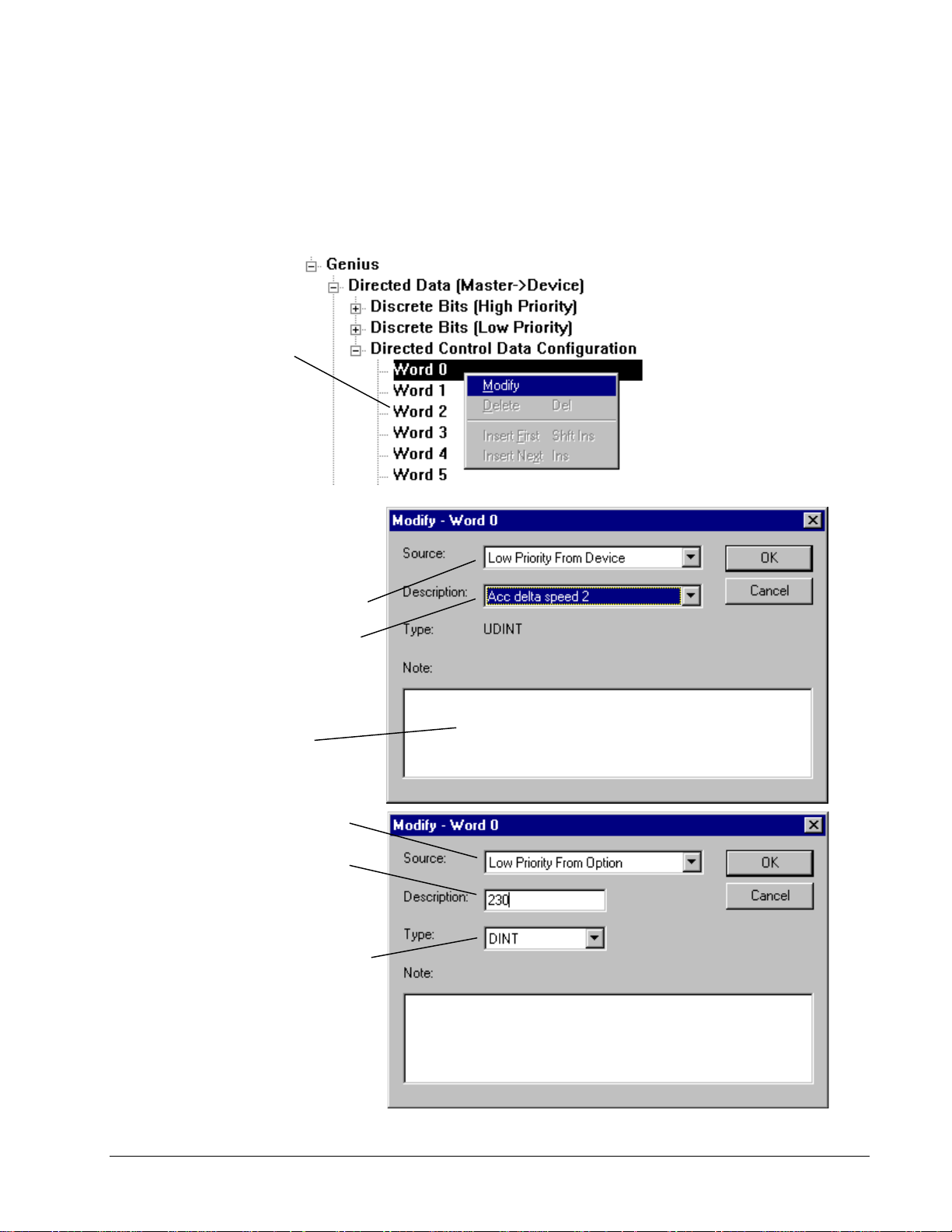
Directed Control Data and Global Data
Two types of word data can be set in the Genius configuration:
•
Directed Data (Master->Device) – data passed from the Genius to the drive
•
Global Data (Device->Master) – data passed from the drive to the Genius
À To set word data
Right mouse click on
the
Word
and select
Modify.
dialog box displays.
Note: To view parameter and
variable
Options
and the tab
then select
(You must be a Level 4: Full Drive
Access user.)
The following
numbers
menu, select
, from the
Setting
AVDV Series Drive
Abbreviated Names.
,
,
Select a
priority and destination of the data
received (To) as Directed Data or
sent (From) as Global data.
If you select
Low Priority To/From Device
High Priority To/From Device
select the
the parameter/variable for this
word and the
displays.
Enter a note, if desired.
If you select
Low Priority To/From Option
(only available with the Digital
General Function (DGF) board),
select an integer
associated with parameters/
variables on the Option board.
Enter a value from 0 to 65532.
Select the
variable (INT and UINT are 16-bit
and all others are 32-bit).
Source
to determine the
Description
Type
Description
Type
of parameter/
or
name of
automatically
If you select
Discrete Bit Word To/From
Device
the Description can be
High Priority
GEH-6405A Toolbox for an AVDV Series Drive Chapter 4 Configuring an AVDV Series Drive • 4-37
or
Low Priority
.
Page 68
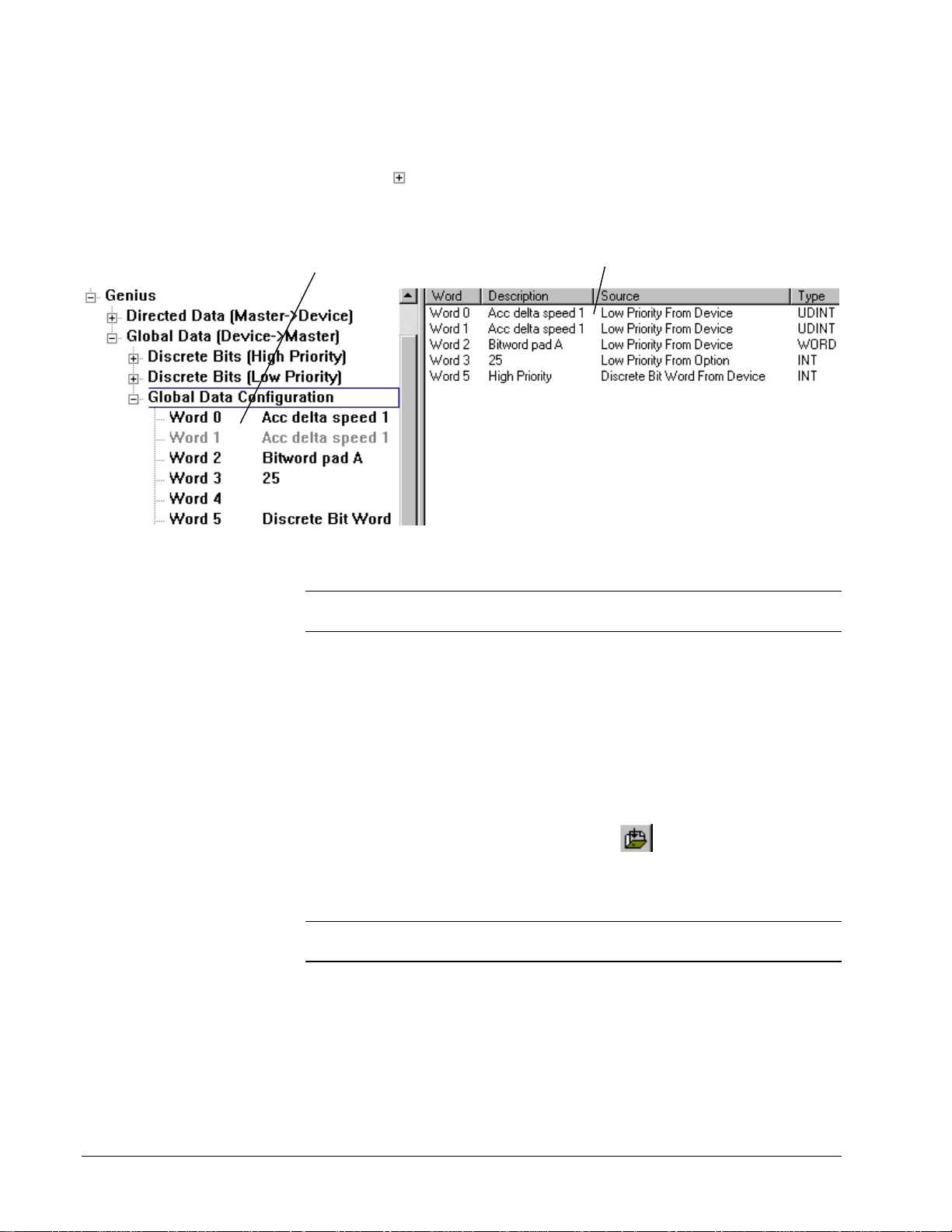
View Word Data
À To view word data
w Click on
A list of the Words displays
(including the description of the
parameter/variable for this bit).
Exporting/Importing Genius Val ues
Note In order to export/import Genius values, they must di splay in the Outline
View. Be sure to select Genius in the drive Edit Device Properties dialog box.
to expand Directed Data Configuration or Global Data
Configuration.
When Global Data Configuration is highlighted,
Summary View
the
bits. (Note: Word 4 does not display because
no data is defined for that word.)
displays all the data for the
À To export Genius values
1. From the Outline View, click on Genius to highl ig ht it.
2. From the File menu, choose Export and Selected. The Export Genius dialog
box displays. The file is saved and named for the current drive configuration,
such as AVDV_GeniusValues.tre.
À To import Genius values
1. From the Outline View, click on Genius to highl ig ht it.
2. From the File menu, choose Import or click
. Choose the file to import.
Downloading and Uploading
Note Make sure Genius is selected in the drive Edit Device Properties dialog box
and that the serial cable is plugged into the RS-232C port of the Genius board.
À To download or upload Genius configuration
1. From the Outline View, right-mouse click on Genius.
2. From the drop-down menu choose Download or Upload
4-38 • Chapter 4 Configuring an AVDV Series Drive GEH-6405A Toolbox for an AVDV Series Drive
Page 69
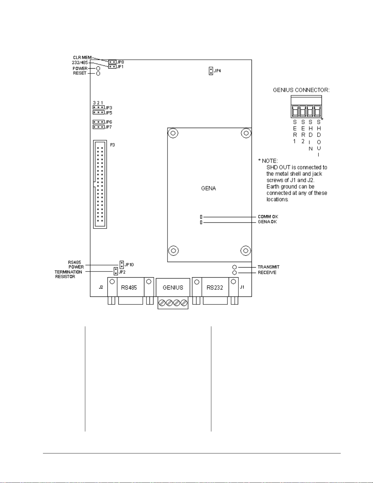
Hardware Settings
Jumper Settings
JP1 On - If using the RS-232C port
Off - If using the RS-485 port
JP2 On - If using RS-485 port and
Genius board is last device on
network (default)
Off - If using RS-485 port and
Genius board is in middle of the
network
JP3
JP4
JP5 Always on pins 1 & 2
GEH-6405A Toolbox for an AVDV Series Drive Chapter 4 Configuring an AVDV Series Drive • 4-39
Always on pins 1 & 2
Always on
JP6 Always on pins 1 & 2
JP7 Always on pins 1 & 2
JP8
On - To clear Genius board settings on
power up
Off - To retain Genius board settings
on power up
Not used
JP9
JP10 On - 5 Vdc Power is supplied to the
RS-485 port
Off - No power is supplied to the RS-
485 port
Page 70

Port Connections
RS-232C Port Pinout (J1)
Pin
2 TXD (output)
3 RXD (input)
5GND
7 CTS (input)
8 RTS (output)
RS-485 Port Pinout (J2)
Pin
3 Signal A
7 Signal B
5GND
9 +5 V dc (If JP10 is installed)
Genius Pinout (between J1 and J2)
Pin
1 Serial 1 (closest to J2)
2 Serial 2
3 Shield In
4 Shield Out
LEDs
Genius Board LEDs
D1 Power OK
D2 Reset
D3 Receive
D4 Transmit
GENA LEDs
1 GENA OK
2 Comm OK
4-40 • Chapter 4 Configuring an AVDV Series Drive GEH-6405A Toolbox for an AVDV Series Drive
Page 71

Glossary of Terms
ASCII
American Standard Code for Information Interchange. An 8-bit code used for data.
attributes
Information, such as location, visibility, and type of data that sets something apart
from others. In signals, an attribute can be a field within a record.
baud
A unit of data transmission. Baud rate is the number of bits per second transmitted.
BIOS
Basic input/output system. Performs the boot-up, which includes hardware self-tests
and the file system loader. The BIOS is stored in EEPROM and is not loaded from
the toolbox.
bit
Binary Digit. The smallest unit of memory used to store only one piece of
information with two states, such as One/ Zero or On/Off. Data requiring more than
two states, such as numerical values 000 to 999, requires multiple bits (see Word).
board
Printed wiring board.
Boolean
Digital statement that expresse s a condition that is either True or False. In the
toolbox, it is a data type for logical signals.
bus
An electrical path for transmitting and receiving data.
bumpless
No disrupt to the control when downloading.
byte
A group of eight binary digits (bits) operated on a single unit.
GEH-6405 Toolbox for an AVDV Series Drive Glossary of Terms • G1
Page 72

COM port
Serial communication ports (two). COM1 is reserved for diagnostic information and
the Serial Loader. COM2 is used for I/O communication
configure
To select specific options, either by setting the location of hardware jumpers or
loading software parameters into memory.
dead band
A range of values in which the incoming signal can be altered without changing the
outgoing response.
device
A configurable component of a process control system.
Diagram
Click on this item in the Outline View for an overall picture (in the Summary View)
of drive function.
diagram links
Click on a button to go to other pages of diagrams or information on drive functions.
Drive Control
Enables you to control the drive from the toolbox, the same as the keypad on the
cabinet door.
EIA
Electronics Industry Association (EIA), a trade organization representing the U.S.A.
high technology community. The EIA establishes Recommended Standards (RS) for
hardware devices and their interfaces.
EEPROM (EE)
Electronically erasable programmable read-only memory.
fault
A message from the drive indicating a warning or failure.
Finder
A subsystem of the toolbox for searching and determining the usage of a particular
item in a configuration.
firmware
The set of executable software that is stored in memory chips that hold their content
without electrical power, such as EEPROM.
flash
A non-volatile programmable memory device.
G2 • Glossary of Terms GEH-6405 Toolbox for an AVDV Series Drive
Page 73

font
One complete collection of letters, punctuation marks, n umbers, and special
characters with a consistent and identifiable typeface, weight, posture, and size.
hexadecimal (hex)
Base 16 numbering system using the digits 0-9 and letters A-F to represent the
decimal numbers 0-15. Two hex digits represent 1 byte.
initialize
To set values (addresses, counters, registers, and such) to a beginning value prior to
the rest of processing.
insert
Adding an item either below or next to another item in a configuration, as it is
viewed in the hierarchy of the Outline View of the toolbox.
logical
A statement of a true sense, such as a Boolean.
model
Interactive setup data (recipe) that automatically adj usts to the process. This function
is usually used with hot mills or cold mills.
module
A collection of tasks that have a defined scheduling period.
non-volatile
The memory specially designed to store information even when the power is off.
online
Online mode provides full CPU communications, allowing data to be both read and
written. It is the state of the toolbox when it is co mmunicat ing with the system for
which it holds the configuration. Also, a download mode where the device is not
stopped and then restarted.
parameter
A value used to define drive behavior.
physical
Refers to devices at the electronic or machine level in contrast with logical. Logical
implies a higher view than the physical. Users relate to data logically by data element
name; however, the actual fields of data are physically located in sectors on a disk.
put into database
Command in the device menu used to add configuration information i nto a system
database.
GEH-6405 Toolbox for an AVDV Series Drive Glossary of Terms • G3
Page 74

realtime
Immediate response. It refers to process control and embedded systems, and fast
transaction processing systems that must respond instantly to changing conditions.
reboot
To restart the toolbox.
relay ladder diagram (RLD)
A ladder diagram has a symbolic power source. Power is considered to flow from the
left rail through a contact to the coil connected to the right.
RS-232C
An EIA Recommended Standard (RS) for the serial link communications interface
for interconnecting data terminal equip ment, such as printers, computer monitors, or
computers to data communications equipment, such as modems, for transmission
over a telephone line or network. RS-232C uses an unbalanced or single-ended
voltage interface. (Also see EIA.)
RS-485
An EIA standard for multipoint communications. RS-485 is similar to RS-422 but
can support more nodes per line because it uses lower-impedance drivers and
receivers.
sample set
Set of values taken when signals are being trended together with the Trend Recorder.
sampling rate
The period that values are collected to put in a sample set.
self-tune
Self-tune is a process where the drive and the motor perform predefined tests to
determine the best running conditions for the system.
signal
The basic unit for variable information. Signals are the placeholders for memory
locations in the toolbox’s different platforms.
TCP/IP
Communications protocols developed to inter-network dissimilar systems. It is a de
facto UNIX standard, but is supported on almost all systems. TCP controls data
transfer and IP provides the routing for functions, such as file transfer and e-mail.
toolbox
A Windows-based software package used to configure drives.
trend
A time-based plot to show the history of values.
G4 • Glossary of Terms GEH-6405 Toolbox for an AVDV Series Drive
Page 75

Trend Recorder
A subsystem of the toolbox that monitors and graphs signal values from a drive.
TrueType
Scaleable font technology that renders printer and screen fonts. Each TrueType font
contains its own algorithms for converting the outline into bitmaps.
validate
Makes certain that items or devices do not contain errors and verifies that the
configuration is ready to be downloaded.
var
An AVDV Series variable.
Windows NT
Windows New Technology. Advanced 32-bit operating system from Microsoft for
386s and above. It runs NT-specific applications as well as those written for DOS,
Windows 3.x (16 and 32-bit), OS/2 character mode (non-graphical) and POSIX. NT
does not use DOS; it is a self-contained operating system.
word
A unit of information composed of characters, bits, or bytes, that is treated as an
entity and can be stored in one location. Also, a measurement of memory length,
usually 4, 8, or 16-bits long.
GEH-6405 Toolbox for an AVDV Series Drive Glossary of Terms • G5
Page 76

Notes
G6 • Glossary of Terms GEH-6405 Toolbox for an AVDV Series Drive
Page 77

7R
*(,QGXVWULDO6\VWHPV
7HFKQLFDO3XEOLFDWLRQV5P
Problem Report
General Electric Company
Name Telephone Number
Company Name Fax Number
Address Job Site
GE Requisition Number
Name of Product:
Description of PC Hardware:
Brand Processor Type Processor Speed (MHz)
486 Pentium Other
Description of PC Software
Version (see Help, About Toolbox ) Windows NT Version Amount of Memory
Problem Description (Describe problem thoroughly. Include sequence leading up to problem. If the program experienced a runti m e
error, attach a printout of the error.log file contained in the tools directory).
5RDQRNH%OYG
6DOHP9$86$
)D[
*(,QWHUQDO'&
Detach, fold, and mail − or fax this side only.
Page 78

.........................................................................Fold here and close with staple or tape.........................................................................
Place
stamp
here
GE Motors & Industrial Systems
Product Service, Room 191
1501 Roanoke Blvd.
Salem, VA 24153-6492 USA
............................................................................................. Fold here first..............................................................................................
Page 79

5HDGHU&RPPHQWV
5HDGHU&RPPHQWV
5HDGHU&RPPHQWV
5HDGHU&RPPHQWV
*HQHUDO(OHFWULF&RPSDQ\
*HQHUDO(OHFWULF&RPSDQ\
*HQHUDO(OHFWULF&RPSDQ\
*HQHUDO(OHFWULF&RPSDQ\
:HZHOFRPHFRPPHQWVDQGVXJJHVWLRQVWRPDNHWKLVSXEOLFDWLRQPRUHXVHIXO
7R
*(,QGXVWULDO6\VWHPV
7HFKQLFDO3XEOLFDWLRQV5P
5RDQRNH%OYG
6DOHP9$86$
)D[
*(,QWHUQDO'&
<RXU1DPH 7RGD\¶V'DWH
<RXU&RPSDQ\¶V1DPHDQG$GGUHVV -RE6LWH
*(5HTXLVLWLRQ1R
3XEOLFDWLRQ1R<RXU-RE)XQFWLRQ+RZ<RX8VH7KLV3XEOLFDWLRQ
3XEOLFDWLRQ,VVXH5HYLVLRQ'DWH
*HQHUDO5DWLQJ
([FHOOHQW *RRG )DLU 3RRU $GGLWLRQDO&RPPHQWV
&RQWHQWV BBBBBBBBBBBBBBBBBBBBBBBBBBBBBBBBBBBBBBBBBBBBBBBBBBBBBBBBBBBBB
2UJDQL]DWLRQ BBBBBBBBBBBBBBBBBBBBBBBBBBBBBBBBBBBBBBBBBBBBBBBBBBBBBBBBBBBBB
7HFKQLFDO$FFXUDF\ BBBBBBBBBBBBBBBBBBBBBBBBBBBBBBBBBBBBBBBBBBBBBBBBBBBBBBBBBBBBB
&ODULW\ BBBBBBBBBBBBBBBBBBBBBBBBBBBBBBBBBBBBBBBBBBBBBBBBBBBBBBBBBBBBB
&RPSOHWHQHVV BBBBBBBBBBBBBBBBBBBBBBBBBBBBBBBBBBBBBBBBBBBBBBBBBBBBBBBBBBBBB
'UDZLQJV)LJXUHV BBBBBBBBBBBBBBBBBBBBBBBBBBBBBBBBBBBBBBBBBBBBBBBBBBBBBBBBBBBBB
7DEOHV BBBBBBBBBBBBBBBBBBBBBBBBBBBBBBBBBBBBBBBBBBBBBBBBBBBBBBBBBBBBB
5HIHUHQFLQJ BBBBBBBBBBBBBBBBBBBBBBBBBBBBBBBBBBBBBBBBBBBBBBBBBBBBBBBBBBBBB
5HDGDELOLW\ BBBBBBBBBBBBBBBBBBBBBBBBBBBBBBBBBBBBBBBBBBBBBBBBBBBBBBBBBBBBB
,IQHHGHGKRZFDQZHFRQWDFW\RX"
)D[1R
3KRQH1R
(PDLO
$GGUHVV
6SHFLILF6XJJHVWLRQV
3DJH1R &RPPHQWV
______ __________________________________________________________________________________
______ __________________________________________________________________________________
______ __________________________________________________________________________________
______ __________________________________________________________________________________
______ __________________________________________________________________________________
______ __________________________________________________________________________________
2WKHU&RPPHQWV:KDW\RXOLNHZKDWFRXOGEHDGGHGKRZWRLPSURYHDQGVXFK BBBBBBBBBBBBBBBBBBBBBBBBBBBBBBBBBBBBBBBBBBBBBBBB
___________________________________________________________________________________________
___________________________________________________________________________________________
___________________________________________________________________________________________
___________________________________________________________________________________________
___________________________________________________________________________________________
___________________________________________________________________________________________
2YHUDOOJUDGH&RPSDUHGWRSXEOLFDWLRQVIURPRWKHUPDQXIDFWXUHUVRIVLPLODUSURGXFWVKRZGR\RXUDWHWKLVSXEOLFDWLRQ"
6XSHULRU &RPSDUDEOH ,QIHULRU 'RQRWNQRZ &RPPHQW BBBBBBBBBBBBBBBBBBBBBBBBBBBBBBBBBBBBBBBBBBBB
&RUUHFWLRQVLQIRUPDWLRQWKDWFRXOGEHH[SDQGHGRQDQGVXFK
'HWDFKDQGID[RUPDLOWRWKHDGGUHVVQRWHGDERYH
Page 80

)ROGKHUHDQGFORVHZLWKVWDSOHRUWDSH
BBBBBBBBBBBBBBBBBBBBBBBBBBBB
BBBBBBBBBBBBBBBBBBBBBBBBBBBB
BBBBBBBBBBBBBBBBBBBBBBBBBBBB
*(,QGXVWULDO&RQWURO6\VWHPV
7HFKQLFDO3XEOLFDWLRQV5P
5RDQRNH%OYG
6DOHP9$86$
3ODFH
VWDPS
KHUH
)ROGKHUHILUVW
Page 81

Page 82

*HQHUDO(OHFWULF&RPSDQ\
5RDQRNH%OYG
ZZZJHFRP 6DOHP9$86$
*(,QGXVWULDO6\VWHPV
 Loading...