

Page 1
g
p
g
quip
p
y
GEH5626 Installation Instructions R04
Spectra Series™ Power Panelboards
Circuit Breakers and Modules
WARNING: Danger of electrical shock or injury.
OFF
Turn
switchboard before workin
ment or removing any component. Do
e
not remove circuit
other component until the power is turned
OFF.
ower ahead of the panelboard or
inside the
rotective devices or an
General
These instructions apply to the following catalog numbers:
• Circuit breaker modules AMC6FJ, AMC4FJ, AMC3FJ,
AMC2FJ, AMC6FLS, AMC3FLS, AMC2FLS, and
AMC4FLS
• Circuit breaker frames TFJ, TFK, THFK, TFL, SFHA,
SFLA, and SFPA
Installation
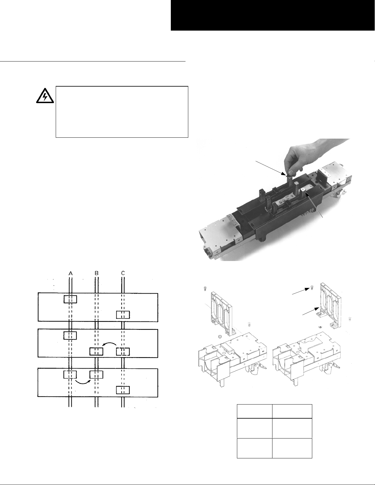
1. Phase balancing for two-pole devices in three-phase
systems. To balance the panelboard load, remove the
screws on the appropriate bus clip, reposition the bus
clip as shown in Figure 1, then install and tighten the
screws to 27–32 in-lb.
2. Prepare the breaker module. Remove the protective
caps or insulating tape only from the tops of the stud
posts to which the circuit breaker is to be attached, as
shown in Figure 2. Fasten the filler supports, as shown
in Figure 3, with #10-32 x
tightened to 15–20 in-lb. The proper position of the
filler support is listed in Table 1.
Protective Cap
or Insulating
Tape
Figure 2. Removing the caps or tape from the stud posts of the
breaker module.
3
/4" hex-head screws
Stud Post
A & C Phase
As Received
A & B Phase
B & C Phase
Figure 1. Repositioning the bus clip to balance the load.
#10-32 x 3/4"
Hex-Head
Screw
Filler
Support
Figure 3. Fastening the filler supports in position.
Breaker
Module
AMC6FJ
AMC4FJ
AMC6FLS
AMC3FJ
AMC2FJ
AMC3FLS
Table 1. Filler support position per module type.
Filler Support
Position
4
1
Page 2
3. Install the circuit breaker.
a. Main devices (lugs only on ON side of circuit
breaker). Place the OFF side of the breaker over the
stud posts, as shown in Figure 4. Fasten the breaker
to the modul e with
washers and #10-32 x 3
1
/4-20 x 3/4" screws with conical
3
/4" screws with #10 flat
washers. After all screws are in place, tighten the
1
/4-20 screws to 40–50 in-lb and the #10-32 screws to
25–30 in-lb.
b. Branch devices (lugs only on OFF side of the
breaker). Remove the lug cover, if present. Place the
ON side of the breaker over the stud posts, as shown
in Figure 4. Secu re the breaker to th e module with
1
/4-20 x 3/4" screws with conical washers and #10-32
3
x 3
/4" screws with #10 flat washers. Do not remove
the protective cap or tape from the top portion of
the stud posts unless a breaker is to be installed in
that position. After all screws are in place, tighten
1
the
/4-20 screws to 40–50 in-lb and the #10-32
screws to 25–30 in-lb. Replace the lug cover, if
present.
For double-branch devices, repeat this procedure
for the other breaker. Breaker types TFJ, TFK,
THFK, or TFL may be com bined and breaker types
SFHA, SFLA, or SFPA may be combined.
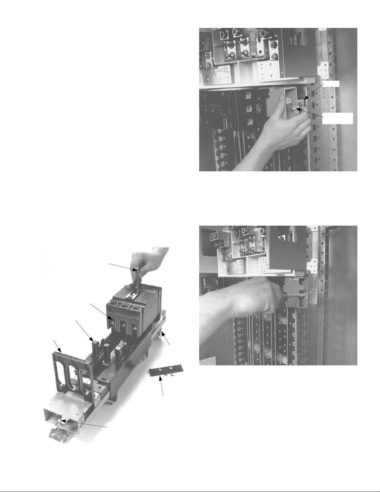
4. Position the breaker module. Loosen the latch lock
screws an d fully retrac t the latches . Line up the gu ide
fingers on bo th ends of the mod ule with the notche s
in the panelb oard interi or rails, as shown in Figur e 5.
Allow no space between units.
Latch
Latch Lock
Screw
Figure 5. Positioning the breaker module.
5. Install the module. Latch one side of the circuit
breaker module. Release the rail latch. Pivot the
module onto the bus bars and engage the second
latch. Release the rail latch. Tighten the rail latch
screws to 25 in-lb, as shown in Figure 6.
Filler
Support
#10-32 Screw
& Flat Washer
1
/4-20 Screw &
Conical Washer
Stud
Post
Latch Lock
Screw
Lug
Cover
Latch
Figure 6. Installing the breaker module.
6. Wire the circuits. Refer to the label on the circuit
breaker for the proper tightening torque.
7. Filler plate kits. Install the appropriate filler plate kits,
as listed in Table 1.
Figure 4. Installing the breaker on the module.
Page 3

Filler Plate
Cat. No. Module Type
AFP3SFD
AFP3SFS
AFP4SFD
AFP4SFS
AMC6FJ
AMC4FJ
AMC3FJ
AMC2FJ
AMC6FLS
AMC4FLS
AMC3FLS
AMC2FLS
Table 1. Filler plate kit for each breaker module type.
Attention – Procedure for Aluminum
Terminations
1. Strip the insulation, being careful to not nick the wire.
2. Clean the wire strands with a wire brush.
3. Thoroughly coat the stripped conductor with a
suitable antioxidant compound, such as ALNOX or
PENETROX A13.
4. Insert the conductor and tighten the connector screw
to the indicated torque, as indicated on the rating
label.
Page 4

g
These instructions do not cover all details or variations in e
quip
y
p
ma
be met in connection with installation, operation, or maintenance. Should further information be desired or should
articular problems arise that are not covered sufficiently for the purchaser’s purposes, the matter should be referred to the
GE Company.
ment nor do they provide for every possible contingency that
GE Industrial Systems
General Electric Company
41 Woodford Ave., Plainville, CT 06062
GEH5626 R04 0701 © 2001 General Electric Company
 Loading...