

Page 1
g
p
g
quip
y
g
g
y
y
DEH070 Installation Instructions R02
Spectra Series™ Power Panelboards
Type AMB Main Lug Kit
Application
These instructions apply to main lug kits with the
following catalog numbers:
AMB2600MA AMB3600MA AMB2600MC
AMB3600MC AMB2120MA AMB3120MA
AMB2120MA AMB3120MC AMB2120DMC
AMB3120DMC AMB2120DMA AMB3120DMA
Installation
WARNING: Danger of electrical shock or injury.
OFF
Turn
switchboard before workin
e
Equipment is to be installed and maintained b
properly trained and qualified personnel only.
1. Orient the lug base with the lug wire holes facing the
end of the box marked
AMB2120MA, AMB3120MA, AMB2120MC,
AMB3120MC, AMB2120DMC, AMB3120DMC,
AMB2120DMA, and AMB3120DMA, feed the lug
tangs through the support, as shown in Figure 1.
Catalog numbers AMB2600MA, AMB3600MA,
AMB2600MC, and AMB3600MC do not contain this
support.
ower ahead of the panelboard or
inside the
ment or removing any component.
LINE. For catalog numbers
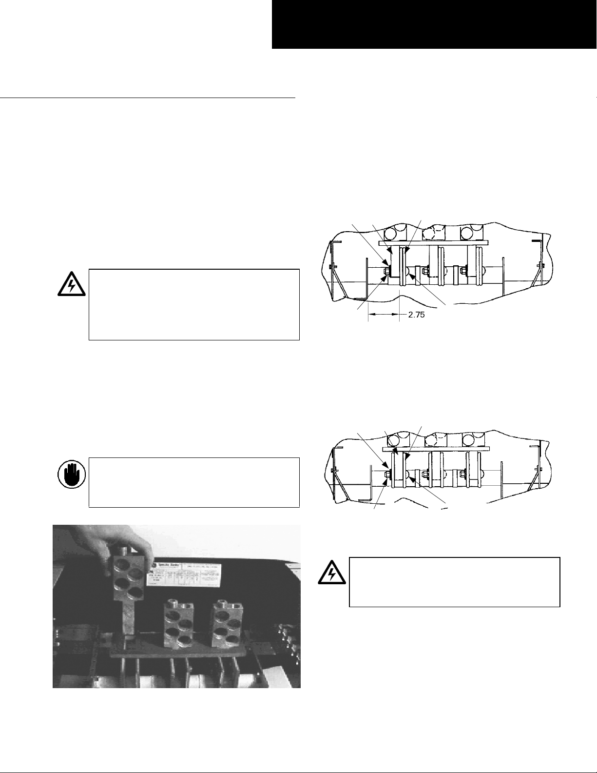
2. Locate the mounting position. For Spectra APNB bolton style interiors, locate the side of the panelboard
interior in which the dimension from the nearest bus
face to the inner face of the bus support rail is 2.75
inches, as shown in Figure 2. Lug tangs will be
mounted on this side of each phase of the bus.
Nut
Conical
Washer
Lug
Tang
Lug
Tang
Conical
Washer
Figure 2. Lug tang position relative to the bus bars of a Spectra
For Spectra APN plug-in style interiors, the lug tangs
are positioned between the buses for each phase, as
shown in Figure 3. For Spectra APN interiors, rated at
600 A or less, the lug tangs are positioned as described
above for Spectra APNB interiors.
Bus
Carriage
Bolt
APNB bolt-on interior.
Bus
CAUTION: Failure to properly insert the lu
tang in the support for the required kits will
cause destructive behavior durin
conditions.
Figure 1. Lug tang inserted into the support.
short-circuit
Nut
Figure 3. Lug tang position relative to the bus bars of a Spectra APN
plug-in interior.
WARNING: Positioning the lugs correctl
relative to the bus bars is crucial to product
and if installed improperly will result in
safet
electrical shock or injury.
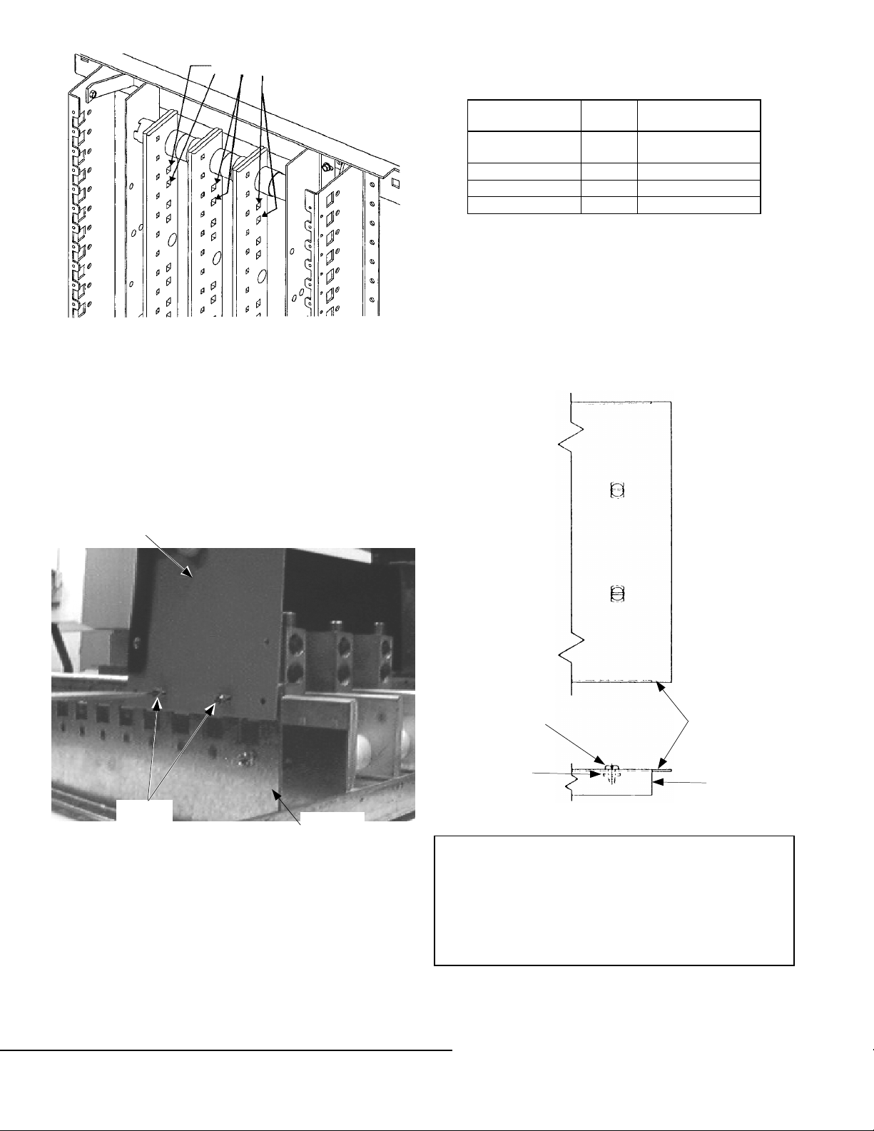
3. Align the mounting holes. Align the lug tang
mounting holes with the first and second bus holes
from the box end stamped
holes, as shown in Figure 4.
Carriage
Bolt
LINE on the rear row of
Page 2
quip
g
p
p
y
purp
g
Mounting Holes
6. Wire the lugs using the conductor sizes and tightening
torques listed in Table 1.
Figure 4. Bus bar mounting holes.
4. Fasten lugs to the bus. Fasten the lug tangs to the bus
using a carriage bolt, flat washer, Belleville washer,
and nut, making certain that the carriage bolt is fed
through the bus first, as shown in Figures 2 and 3.
Tighten these bolted connections to 200–250 in.-lb.
5. Install the wire barriers. Position the upper edge of
the wire barriers flush with the panel side rails or Z
rails, as shown in Figure 5. Fasten the wire barriers to
the panel side rails or Z rails using the thread-forming
screws supplied.
Wire
Barrier
Torque,
Lug Part No.
252B3638G9–10 375
252B3638G1–2 450 2/0–600 kcmil (4)
252B3638G3–8 450 2/0–600 kcmil (8)
GEA2-750 475 3/0–750 kcmil (2)
in.-lb.
Wire Size
(# of wires)
8–500 kcmil (1)
#2/0–600 kcmil (1)
Table 1. Recommended tightening torque and wire sizes.
7. Install the cover. Lug kits whose catalog numbers have
an F suffix include AFPML cover plates. Covers are
included for the following box sizes: 27" and 31" wide,
36" and 40" wide, and 44" wide. Choose the
appropriate cover for the box to be used.
Attach the cover to the barriers in four places with the
screws and nut fasteners provided, as shown in Figure
6. Tighten the screws to 25–30 in.-lb.
Thread-
Forming
Screws
Panel Side
Rail
Figure 5. Installing the wire barriers.
GE Industrial Systems
General Electric Company
41 Woodford Ave., Plainville, CT 06062
DEH070 R02 1001 © 2001 General Electric Company
Screw
Nut
Cover
Barrier
Figure 6. Installing the cover.
These instructions do not cover all details or variations in
e
ment nor do they provide for every possible
contin
installation, o
information be desired or should
that are not covered sufficientl
Company.
ency that may be met in connection with
eration, or maintenance. Should further
articular problems arise
for the purchaser’s
oses, the matter should be referred to the GE
 Loading...