

Page 1
DEH–40026 Installation Instructions
g
INTRODUCTION
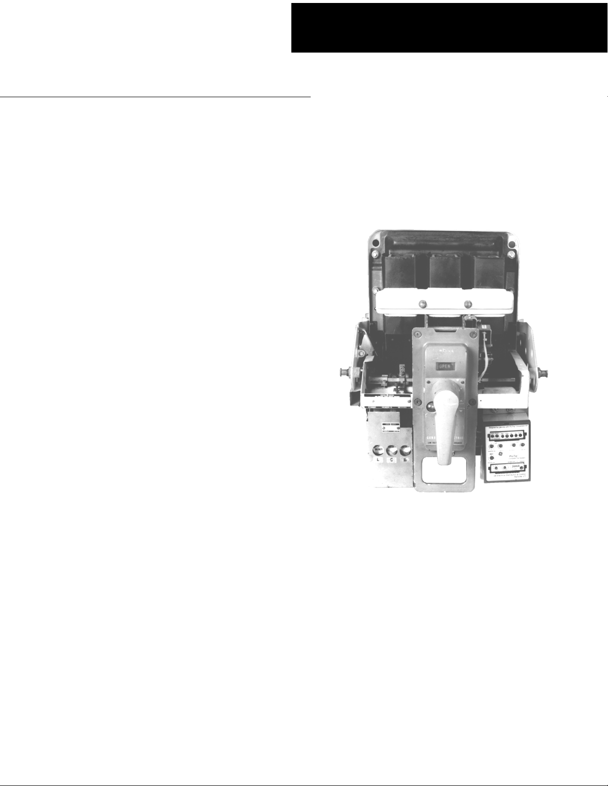
GE Conversion Kits are designed for upgrading existing
GE low-voltage power circuit breakers, rather than
replacing the entire breaker. The Conversion Kits include
ProTrip™ Trip Units, the latest technological advance in
GE trip systems.
ProTrip Conversion Kits are designed and tested to
conform to ANSI Standard C37.59, allowing the retrofitter
to properly install the kit and acceptance test the breaker.
This publication covers installation of ProTrip Conversion
Kits on GE types AK-15, AK-25, and AKU-25 low-voltage
power circuit breakers. Each Conversion Kit contains all
the components needed to convert from an existing GE
trip system.
ProTrip™ Conversion Kits
For GE Types AK-15, AK-25, and AKU25
Low-Voltage Power Circuit Breakers
Page 2

TABLE OF CONTENTS
SECTION 1. GENERAL INFORMATION............................................................................................................4
SECTION 2. BEFORE INSTALLATION..............................................................................................................4
SECTION 3. FRONT-FRAME CONVERSION
Separation of the Front and Back Frames..............................................................................................5
Removal of the Existing Trip Device.......................................................................................................6
Remounting the X and Y Relays.............................................................................................................7
Installing the Flux Shifter.........................................................................................................................8
Installing the Trip Unit Bracket and Trip Unit........................................................................................10
SECTION 4. BACK-FRAME CONVERSION
Current Sensor Installation ...................................................................................................................13
Stud Shield Modification .......................................................................................................................15
Remounting Primary Disconnects ........................................................................................................15
SECTION 5. CONFIGURING THE TRIP UNIT................................................................................................16
SECTION 6. FOUR-WIRE GROUND FAULT OPTION................................................................................16
SECTION 7. TESTING AND TROUBLE-SHOOTING
Testing ..................................................................................................................................................17
Trouble-Shooting...................................................................................................................................17
Nuisance Tripping on Ground Fault-Equipped Breakers.........................................................17
2
Page 3

LIST OF FIGURES
1. Arc chute retainer and arc chutes. ...................................................................................................................5
2. Screw to be removed from connecting links. ................................................................................................... 5
3. Breaker bottom bracket connected to the escutcheon and the back frame.................................................... 6
4. Type EC-2A trip device, with adjacent device removed...................................................................................6
5. Front view of the front frame, showing relocation of the X and Y relays..........................................................7
6. Right side view of the front frame, showing relocation of the Y relay..............................................................8
7. Y relay installed on the arc chute retainer........................................................................................................8
8. Unassembled flux shifter and mounting hardware...........................................................................................8
9. New flux shifter installed on the right side of the breaker mechanism (shown in the
reassembled breaker)......................................................................................................................................9
10. Mounting and adjusting the flux shifter shown from the right side of the mechanism. ....................................9
11. Flux shifter as isntalled on the breaker............................................................................................................ 9
12. Trip unit, mounting plate, support bracket, and harness................................................................................10
13. Trip unit support bracket mounted to the breaker frame on a manually operated stationary
breaker. ..........................................................................................................................................................10
14. Trip unit support bracket mounted to the breaker frame on an electrically operated draw-out
breaker. ..........................................................................................................................................................10
15. Bottom view of the trip unit support bracket installed on an electrically operated breaker,
showing the X relay and insulator.................................................................................................................. 11
16. Trip unit attached to the mounting plate.........................................................................................................11
17. Trip unit and mounting plate attached to the breaker. ...................................................................................12
18. Flux shifter wiring harness in place................................................................................................................ 12
19. Components for the current sensor assembly for one pole...........................................................................13
20. Current sensor assembly, right-side view......................................................................................................13
21. CT terminal board bracket and insulator installed..........................................................................................13
22. Completed CT installation..............................................................................................................................13
23. Right-side view of the back frame, showing installation of the flux shifter actuator bushing.........................14
24. Modification of the lower stud shields............................................................................................................ 15
25. Primary disconnect modification for AK-15 breakers..................................................................................... 15
26. Neutral sensor outline ....................................................................................................................................16
27. Cabling diagram for PtoTrip™ trip units with ground fault on four-wire loads...............................................19
3
Page 4

SECTION 1. GENERAL INFORMATION
GE Conversion Kit installation is straightforward, but
does require careful workmanship and attention to these
instructions. Familiarity with the breaker is highly
desirable. Then general approach is to first remove the
existing trip devices from the breaker, then install the
ProTrip components. Following this procedure, the
converted breaker is performance tested before it is
returned to service.
The majority of trip unit kit installations do not require any
customized assembly work. However, some installations
may involve unusual mounting conditions or accessory
combinations that require minor modifications and/or
relocation of components. In most instances, this
supplementary work can be done on site.
In preparation for the conversion, the installer should
verify that the appropriate current sensors and trip unit
have been furnished. Whenever a ProTrip kit is installed
on a breaker with a four-wire system, an associated
neutral sensor (CT) is required for separate mounting in
the equipment. Ensure that retrofitted breakers are
applied within their short-circuit ratings.
Note that all ProTrip trip units supplied with conversion
kits are equipped with long-time, short-time,
instantaneous, and defeatable ground fault (LSIGX) trip
functions. The installer should be aware of how these
functions will affect his application before installing the
conversion kit.
As a service-related consideration, the installation of a
ProTrip kit provides an excellent opportunity to perform
normal maintenance on the breaker, particularly when
the front and back frames are separated. Such
procedures are described in the installation and
maintenance manuals supplied with the breaker and
equipment.
SECTION 2. BEFORE INSTALLATION
Before starting any work, turn off and lock out all power
sources leading to the breaker, both primary and
secondary. Remove the breaker to a clean, well-lighted
work area.
WARNING: Low-voltage power circuit breakers use
high-speed, stored-energy spring operating
mechanisms. The breakers and their enclosures
contain interlocks and safety features intended to
provide safe, proper operating sequences. For
maximum personnel protection during installation,
operation, and maintenance of these breakers, the
following procedures must be followed. Failure to follow
these procedures may result in personal injury or
property damage.
• Only qualified persons, as defined in the National
Electrical Code, who are familiar with the installation
and maintenance of low-voltage power circuit
breakers and switchgear assemblies, should
perform any work on these breakers.
• Completely read and understand all instructions
before attempting any breaker installation,
operation, maintenance, or modification.
• Turn off and lock out the power source feeding the
breaker before attempting any installation,
maintenance, or modification. Follow all lock-out
and tag-out rules of the National Electrical Code and
all other applicable codes.
• Do not work on a closed breaker or a breaker with
the closing springs charged. Trip an OPEN breaker
and be sure the stored-energy springs are
discharged, thus removing the possibility that the
breaker may trip OPEN or the closing springs
discharge and cause injury.
• Trip the breaker OPEN, then remove the breaker to
a well-lighted work area before beginning work.
• Do not perform any maintenance that includes
breaker charging, closing, tripping, or any other
function that could cause significant movement of a
draw-out breaker while it is on the draw-out
extension rails.
• Do not leave the breaker in an intermediate position
in the switchgear compartment. Always leave it in
the CONNECTED, TEST, or DISCONNECTED
position. Failure to do so could lead to improper
positioning of the breaker and flashback.
4
Page 5
SECTION 3. FRONT-FRAME
CONVERSION
Front-frame conversion consists of the following steps:
1. Separation of the front and back breaker frames.
2. Removal of the existing trip devices.
3. On electrically operated breakers with EC trip
devices, relocating and remounting the X and Y
relays.
3. Installation of the flux shifter and trip paddle.
4. Installation of the trip unit mounting bracket.
5. Installation of the trip unit wire harness.
Separation of the Front and Back Frames
Use the following procedure to separate the front and
back frames of the breaker.
1. Remove the breaker from its enclosure and place it
on a suitable work surface.
2. Verify that closing springs are discharged and that
the breaker is OPEN.
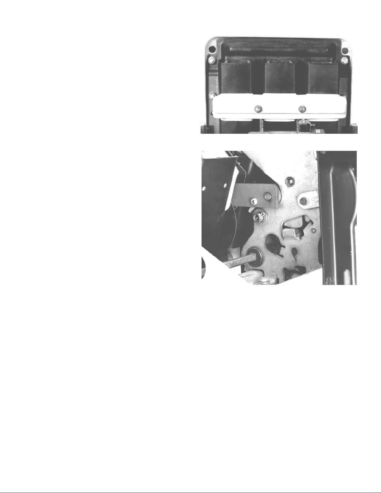
3. Loosen the two captive nuts and lift off the arc chute
retainer, shown in Figure 1.
4. Lift the three arc chutes straight up and out of the
breaker.
5. Remove the long screw and nut through the two
connecting links on each side of the breaker, as
shown in Figure 2.
6. Carefully place the breaker on its back surface,
resting on the primary disconnects.
Figure 1. Arc chute retainer and arc chutes.
Figure 2. Screw to be removed from connecting links.
5
Page 6
7. Remove the two mounting screws and lock washers
attaching the bottom bracket to the escutcheon, as
shown in Figure 3.
8. Loosen the recessed Allen screw in the side of the
charging handle base and lift off the handle.
9. Remove the snap ring and flat washer on the
charging handle mounting shaft.
10. Remove the four Philips-head screws and lock
washers on the front of the escutcheon and lift off the
escutcheon.
11. Lift the bottom bracket from its back frame
attachment.
12. Remove the nuts and washers securing the front
frame to the two long studs from the back frame.
13. Remove the nuts and washers on the studs connecting the front frame bracket to the back frame
(one on each side).
14. Lift the front frame off the back frame.
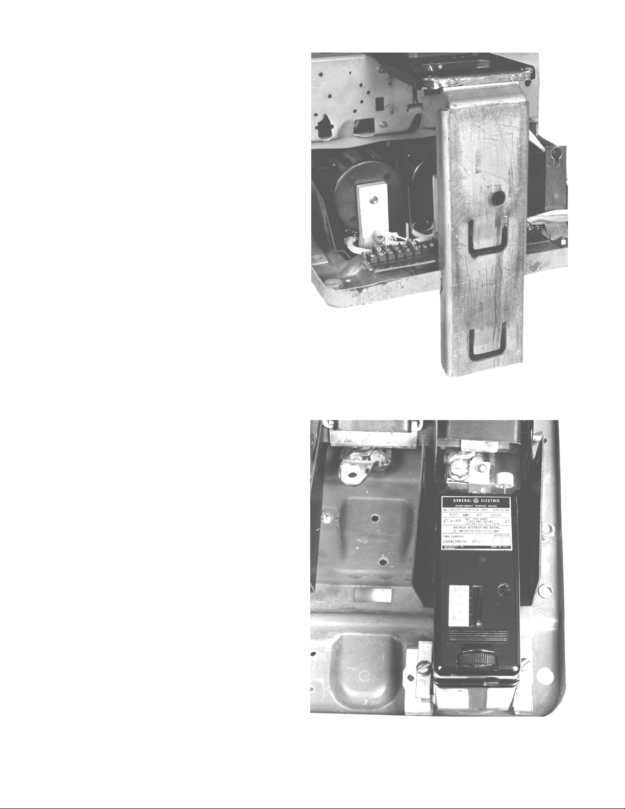
Removal of the Existing Trip Device
Figure 4 shows an existing Type EC-2A trip device with
the adjacent trip device already removed, to illustrate this
procedure.
1. Remove the existing overcurrent trip devices and trip
paddles.
2. On draw-out breakers, remove the primary disconnects from the bottom (load) copper studs.
3. Remove the three bottom (load) copper stud
assemblies. On Power Sensor-equipped breakers,
these will have been removed with the trip devices.
4. On breakers equipped with Type EC trip devices,
remove and discard the mounting brackets on the
lower front of the back frame.
Figure 3. Breaker bottom bracket connected to the
escutcheon and the back frame.
Figure 4. Type EC-2A trip device, with adjacent device
removed.
6
Page 7

Remounting the X and Y Relays
On electrically operated breakers equipped with Type EC
trip devices, the Y relay is mounted on the front frame at
the right side of the operating mechanism.
1. To provide mounting space for the new flux shifter,
remove the Y relay and remount it on the left end of
the arc chute retainer, as illustrated in Figures 5, 6,
and 7.
2. Modify the breaker’s wiring harness to suit. The X
relay should be remounted after the trip unit mount
and bracket are installed, as described in Installing
the Trip Unit Bracket.
Figure 5. Front view of the front frame, showing relocation of the X and Y relays.
7
Page 8

Installing the Flux Shifter
Figure 8 shows the unassembled flux shifter and its
mounting hardware. The flux shifter is mounted to the
right of the operating mechanism, as shown in Figure 9.
1. Remove the existing flux shifter device.
2. Mount the flux shifter trip paddle on the breaker’s trip
shaft as shown in Figures 9 and 10. Push the drawout locking lever in to allow the trip bar to rotate to an
accessible point.
3. Save the new actuating bushing for installation in the
right operating link in the back frame, as described in
Section 4.
4. Mount the flux shifter assembly to the right side of
the front frame, as shown in Figures 9 and 10. On
Power Sensor breakers equipped with a shunt trip,
mount the flux shifter on top of the shunt trip bracket.
If no shunt trip is installed, use the
provided, as indicated in Figures 10 and 11. On ECequipped breakers, the mounting hole must be drilled
and tapped for a #10-32 screw.
1
/8-inch spacer
Figure 6. Right side view of the front frame, showing
relocation of the Y relay.
Figure 7. Y relay installed on the arc chute retainer.
Figure 8. Unassembled flux shifter and mounting
hardware.
8
Page 9

5. When the flux shifter and its trip paddle are installed
and the front and back frames are reassembled, the
flux shifter must be adjusted as follows:
a. Make sure that the breaker mechanism is OPEN,
then charge the closing springs with the charging
handle.
b. Set the gap between the trip paddle and the end
of the flux shifter trip rod, as shown in Figure 10.
Use a 0.10-inch rod as a gage. To make the
adjustment, loosen the jam nut, then turn the
adjusting nut as necessary. Be sure to relock the
adjustment with the jam nut.
6. Optional test – The flux shifter may be tested by
closing the breaker and applying a 9 Vdc power
source to the flux shifter leads (the red wire is
positive). The breaker should trip.
Figure 9. New flux shifter installed on the right side of the
breaker mechanism (shown in the reassembled breaker).
Figure 10. Mounting and adjusting the flux shifter shown
from the right side of the mechanism.
Figure 11. Flux shifter as installed on the breaker.
9
Page 10

Installing the Trip Unit Bracket and Trip Unit
The ProTrip Trip Unit mounts on the lower right side of
the breaker. The trip unit, mounting plate, support
bracket, and wiring harness are shown in Figure 12.
Figure 13. Trip unit support bracket mounted to the
breaker frame on a manually operated stationary
breaker.
Figure 12. Trip unit, mounting plate, support bracket, and
harness.
1. For an electrically operated breaker, attach the X
Relay to the inside of the trip unit support bracket
with the three #10 screws and lock washers
provided, as illustrated in Figures 14 and 15. Be sure
to install the insulating shield between the relay and
the support bracket, as shown.
2. Modify the X Relay harness by adding 16-gauge
extension wire, splices, and ring terminals, as
provided. Work one wire at a time. Route the wires
as shown in Figure 5, ensuring that the wires do not
interfere with the closing solenoid plunger or the trip
unit.
3. Mount the support bracket to the two tapped holes on
the right side of the breaker with the screws and lock
washers provided, as in Figure 13 for a manually
operated breaker and in Figure 14 for an electrically
operated breaker.
Figure 14. Trip unit support bracket mounted to the
breaker frame on an electrically operated draw-out
breaker.
10
Page 11

4. Insert the 50-pin connector on the wiring harness
through the rear of the rectangular hole in the
mounting plate and secure with the two small screws
provided to the mounting plate, as shown in Figure
16.
5. Remove the large screw from the rear of the trip unit.
Line up the connector on the rear of the trip unit with
the connector on the mounting plate and join them.
Insert the large screw just removed through the rear
of the mounting plate to secure the trip unit, as
shown in Figure 16.
Figure 15. Bottom view of the trip unit support bracket
installed on an electrically operated breaker, showing the
X relay and insulator.
Figure 16. Trip unit attached to the mounting plate..
11
Page 12

6. Attach the mounting plate with the three screws and
lock washers provided to the tapped holes in the
support bracket, as shown in Figure 17.
7. Run the wiring harness from the flux shifter through
the wiring trough on the front of the frame, as shown
in Figure 18. Attach the 4-pin connector to the
corresponding connector on the trip unit wiring
harness.
8. The additional three pairs of terminals on the trip unit
wiring harness will be connected to the current
sensors after the breaker has been reassembled.
Figure 17. Trip unit and mounting plate attached to the
breaker.
12
Figure 18. Flux shifter wiring harness in place.
Page 13

SECTION 4. BACK-FRAME
CONVERSION
The components used in the installation of the current
sensor for each pole are shown in Figure 19.
Figure 19. Components for the current sensor assembly
for one pole.
Figure 20. Current sensor assembly, right-side view.
Current Sensor Installation
The three current sensors (CTs) are mounted to the back
frame in the locations from which the existing trip devices
were removed. The following installation process is
illustrated in Figure 20.
1. Insert the lower copper stud through the rectangular
slot in the back frame and attach it with the existing
mounting screw.
2. Place the right-angle bus strap in position in the back
frame and loosely attach it with the existing bolt.
3. Insert the copper sleeve into the center of the CT,
then place the CT in position between the bus strap
and lower stud. Loosely secure it with the long bolt
through the bus strap and CT into the tapped hole in
the stud.
3
4. Align the assembly, then tighten the two
bolts in the bus strap to 250 in-lb to assure proper
contact integrity.
5. Install the CT terminal board-mounting bracket below
the CTs with the two #8-32 ×
provided, as shown in Figure 21. Bring the screws in
from the rear through the existing holes in the back
frame.
6. Install the insulator and bracket to the right side of
the back frame below the CTs with the screws and
nuts provided, as shown in Figure 21.
7. Mount the terminal boards from each CT to the
bracket with the six #6-32 ×
washers provided, as shown in Figure 22.
1
/2-inch screws
1
/2-inch screws and
/8-inch
Figure 21. CT terminal board bracket and insulator
installed..
Figure 22. Completed CT installation..
13
Page 14

8. Remove the bushing from the right operating link and
replace it with the new flux shifter actuating bushing,
as illustrated in Figure 23. On pre-1969 breakers, the
hole in the link must be enlarged to
diameter.
9. Reassemble the front and back frames, using the
reverse of the procedure described in Section 3,
Separation of the Front and Back Frames. Be sure to
engage the flux shifter actuator bushing on the right
operating link with the flux shifter operating lever, as
illustrated in Figure 10.
10. Bring the three CT wires back from the trip unit to the
back frame and connect to the CT terminal boards,
as shown in Figure 22. The lengths of the wires as
supplied assure connection to the proper terminal
board. Note that the black wire (tap) connects to the
left terminal and the white wire (common) to the right
terminal.
7
/16-inch
Figure 23. Right-side view of the back frame, showing
installation of the flux shifter actuator bushing.
14
Page 15

Stud Shield Modification
Modify the left- and right-pole lower stud insulator shields
as illustrated in Figure 24. Remount on the back plate
using the original screws and special nuts supplied with
the kit.
Remounting Primary Disconnects
On draw-out breakers, remount the primary disconnect
fingers to the new lower studs.
On AK-15 breakers only, use the following procedure to
modify the primary disconnects, as illustrated in Figure
25.
1. Place the spacer with the off-center hole in the hole
in the stud, while sliding the new retainer completely
over the stud.
2. Place the new retaining ring on the stud. Insert the tip
of the upper fingers under the retaining ring and
place the bow-tie spacers in the fingers.
3. Place the retainer over the upper fingers and insert
the bolt.
4. Inset the tip of the lower fingers under the retaining
ring and place the bow-tie spacers in the fingers.
Locate the lower retainer to hold the bow-tie spacers
in place.
5. Place the cylindrical spacer and spring on the bolt
and secure it with a washer and nut.
6. Tighten the nut to obtain 60–70 pounds of pressure
per set of four fingers when the fingers are spread
inch apart. If a pressure gauge is not available,
compress the spring to
pressure.
13
/16 inch to obtain proper
1
/2
Figure 24 Modification of the lower stud shields.
CAUTION: Adequate primary contact force is essential.
Tighten the nuts on the 1/4 × 20 mounting bolts to obtain
a spring dimension of 13/16 to 27/32 inch. The proper
distance between the contact fingers is 7/16 inch. Proper
contact force is 60–70 pounds, with the contacts spread
to 1/2 inch.
Figure 25. Primary disconnect modification for AK-15
breakers.
15
Page 16

SECTION 5. CONFIGURING THE TRIP
UNIT
See DEH-40034 for detailed instructions for setting up
ProTrip trip units.
SECTION 6. FOUR-WIRE GROUND
FAULT OPTION
The ground fault option for four-wire installations requires
the installation of an additional current sensor on the
neutral bus in the equipment. The sensor is connected to
the trip unit through the connector provided in the wiring
harness.
1. Mount the neutral sensor on the outgoing neutral
lead, normally in the bus or cable compartment in the
equipment. Figure 26 shows the outline of the neutral
sensor.
2. Connect the neutral sensor wire harness to the
correct taps on the sensor. To maintain the same
polarity as the phase sensors, connect the white wire
to the common terminal, black to the tap.
3. Route the wires through the equipment and connect
to the two-pin connector on the trip unit wiring
harness. The wires should be tied to the breaker
frame in an easily accessible location. It may be
located with the communication harness.
Figure 26. Neutral sensor outline.
16
Page 17

SECTION 7. TESTING AND TROUBLESHOOTING
WARNING: Do not change taps on the current sensors
or adjust the trip unit settings while the breaker is
carrying current. Failure to adhere to these instructions
will void all warranties.
Testing
Before installing a converted breaker back into service,
perform the following steps:
1. Verify that the trip unit is securely installed by
performing a continuity test on the CT wiring and the
trip unit.
a. Disconnect the black CT wires at each phase
sensor.
b. Check for continuity with a continuity tester or
VOM from the white lead of the phase A CT to the
white lead of the phase B CT.
c. Repeat this continuity test for the white leads of
the phase A and phase C CTs.
d. Measure the resistance across each phase
sensor and compare the values measured to the
values listed in Table 1.
e. Reconnect the black CT leads to all of the phase
sensors. Ensure that this is done before
continuing with performance testing of the
breaker.
CAUTION: In addition to the continuity test described in
Step 1 and before performance testing of the converted
breaker, each phase of the breaker should be primary
injected with a current level of about 10%, but no more
than 20%, of the CT rating.
WARNING: If the converted breaker is energized or
tested by primary injection with a sufficiently high test
current with a loose or open circuit between the CTs
and the trip unit, damage will occur to the trip unit, wire
harness, 50-pin trip unit connector, and CTs. Failure to
adhere to these instructions will void all warranties.
2. Check the insulation on the primary circuit with a
1,000-volt Meggar.
3. Measure the resistance across the line and load
terminals for each phase using a micro-ohmmeter or
millivolt tester. If the resistance differs considerably
from phase to phase, the electrical connections may
not be properly tightened or it could also indicate
improper contact wipe.
4. To verify that the breaker has been properly retrofitted, perform a primary injection test on each phase.
This test will check the CTs, bus, wiring harness, flux
shifter, and trip unit as a complete system.
a. A high-current, low-voltage power supply should
be connected across each line and load terminal
to simulate an overcurrent fault.
b. Set the long-time trip at 0.5 to minimize the
breaker stress.
c. When ground fault is installed, the test can be
performed by wiring two adjacent poles in series
or by using the GE Digital Test Kit, cat. no.
TVRMS2. This will prevent the breaker from
tripping because of an unbalanced current flow.
CAUTION: Do not attempt to use GE Test Kit cat. no.
TVTS1 or TVRMS on this trip unit.
Trouble-Shooting
When malfunctioning is suspected, first examine the
breaker and its power system for abnormal conditions
such as the following:
• The breaker is not tripping in response to overcurrent conditions or incipient ground faults.
• The breaker is remaining in a trip-free state because
of mechanical interference along its trip shaft.
• The shunt trip (if present) is activating improperly.
Nuisance Tripping on Ground Fault-Equipped
Breakers
When nuisance tripping occurs on breakers equipped
with ground fault trip, a probable cause is the existence
of a false ground signal. Each phase sensor is connected
to summing circuitry in the trip unit. Under no-fault
conditions on three-wire load circuits, the currents add to
zero and no ground signal is developed. This current
sum is zero only if all three sensors have the same
electrical characteristics. If one sensor differs from the
others (such as by a different rating or wrong tap setting),
the circuitry can produce an output sufficient to trip the
breaker. Similarly, a discontinuity between any sensor
and the trip unit can cause a false trip signal.
The sensors and their connections should be closely
examined if nuisance tripping is encountered on any
breaker whose ProTrip trip unit has previously
demonstrated satisfactory performance. After disconnecting the breaker from all power sources, perform
the following procedure:
1. Check that all phase sensors are the same type
(current range).
2. Verify that the tap settings on all three phase sensors
are identical.
3. Verify that the wiring harness connections to the
sensors have the proper polarity (white lead to
common, black lead to tap), as shown in the cabling
diagram in Figure 27.
4. On ground fault breakers serving four-wire loads,
check that the neutral sensor is properly connected,
17
Page 18

as indicated in Figure 27. In particular, check the
following:
a. Verify that the neutral sensor has the same rating
and tap setting as the phase sensors.
b. Verify continuity between the neutral sensor and
its equipment-mounted secondary disconnect
block. Also check for continuity from the breakermounted neutral secondary disconnect block
through to the trip unit wiring harness connector.
c. If the breaker’s lower studs connect to the power
source, then the neutral sensor must have its load
end connected to the source.
d. Verify that the neutral conductor is carrying only
the neutral current associated with the breaker’s
load current (the neutral is not shared with other
loads).
5. If the preceding steps fail to identify the problem,
then measure the sensor resistances. The appropriate values are listed in Table 1. Since the phase
and neutral sensors are electrically identical, their
resistances should agree closely.
Breaker CT Rating, A Resistance,
ohms
AK-15
AK-25
AKU-25
150
225
225
600
7–15
12–20
12–20
40–50
Table 1. CT resistance values.
18
Page 19

Figure 27. Cabling diagram for ProTrip™ trip units with ground fault on four-wire loads.
19
Page 20

These instructions do not cover all details or variations in equipment nor do they provide for every possible contingency
that may be met in connection with installation, operation, or maintenance. Should further information be desired or should
particular problems arise that are not covered sufficiently for the purchaser’s purposes, the matter should be referred to the
GE Company.
g GE Industrial Systems
General Electric Company
41 Woodford Ave., Plainville, CT 06062
DEH40026 R03 0899 © 1999 General Electric Company
 Loading...