

GE Healthcare Portascan Service Manual
Portascan
Portable Bladder Scanner
Service Manual
GE Healthcare
Portascan Service and Assembly Manual
MAN-004-049
Issue 1

Table of Contents
Mediwatch Service Department
Service Documentation
© Mediwatch UK Ltd
Cosford Lane, Rugby CV21 1QN
Phone +44 1788 547888 Fax +44 1788 536434
Section 1
Service Information
Chapter 1. Introduction
About this manual . . . . . . . . . . . . . . . . . . . . . . . . . . . . . . . . . . . . . . . . . . . . . . . . . . . . . . . . . . . . . . . . . . . . . . . 1
Chapter 2. Warnings and Precautions
Warnings . . . . . . . . . . . . . . . . . . . . . . . . . . . . . . . . . . . . . . . . . . . . . . . . . . . . . . . . . . . . . . . . . . . . . . . . . . . . . . . . 1
Precautions . . . . . . . . . . . . . . . . . . . . . . . . . . . . . . . . . . . . . . . . . . . . . . . . . . . . . . . . . . . . . . . . . . . . . . . . . . . . . . 1
Chapter 3. Technical Specifications of the Scanner
General Specifications . . . . . . . . . . . . . . . . . . . . . . . . . . . . . . . . . . . . . . . . . . . . . . . . . . . . . . . . . . . . . . . . . . . . 2
Acoustic Output information . . . . . . . . . . . . . . . . . . . . . . . . . . . . . . . . . . . . . . . . . . . . . . . . . . . . . . . . . . . . . . 2
Chapter 4. Connector overview
Connections . . . . . . . . . . . . . . . . . . . . . . . . . . . . . . . . . . . . . . . . . . . . . . . . . . . . . . . . . . . . . . . . . . . . . . . . . . . . . 3
Main board . . . . . . . . . . . . . . . . . . . . . . . . . . . . . . . . . . . . . . . . . . . . . . . . . . . . . . . . . . . . . . . . . . . . . . . . . . . . . . 3
ETX Board . . . . . . . . . . . . . . . . . . . . . . . . . . . . . . . . . . . . . . . . . . . . . . . . . . . . . . . . . . . . . . . . . . . . . . . . . . . . . . . 3
Chapter 5. Planned Maintenance
Handling and Care . . . . . . . . . . . . . . . . . . . . . . . . . . . . . . . . . . . . . . . . . . . . . . . . . . . . . . . . . . . . . . . . . . . . . . . 4
Handling and Care probes . . . . . . . . . . . . . . . . . . . . . . . . . . . . . . . . . . . . . . . . . . . . . . . . . . . . . . . . . . . . . . . . 4
Agents and procedures that may damage the probes. . . . . . . . . . . . . . . . . . . . . . . . . . . . . . . . . . . . . . 4
Chapter 6. Unit Disassembly
Images . . . . . . . . . . . . . . . . . . . . . . . . . . . . . . . . . . . . . . . . . . . . . . . . . . . . . . . . . . . . . . . . . . . . . . . . . . . . . . . . . . 5
Chapter 7. Faults and Solutions
Screen Related . . . . . . . . . . . . . . . . . . . . . . . . . . . . . . . . . . . . . . . . . . . . . . . . . . . . . . . . . . . . . . . . . . . . . . . . . . . 7
Probe Related . . . . . . . . . . . . . . . . . . . . . . . . . . . . . . . . . . . . . . . . . . . . . . . . . . . . . . . . . . . . . . . . . . . . . . . . . . . . 7
Keypad Related . . . . . . . . . . . . . . . . . . . . . . . . . . . . . . . . . . . . . . . . . . . . . . . . . . . . . . . . . . . . . . . . . . . . . . . . . . 7
Software Related . . . . . . . . . . . . . . . . . . . . . . . . . . . . . . . . . . . . . . . . . . . . . . . . . . . . . . . . . . . . . . . . . . . . . . . . . 7
Chapter 8. Parts list . . . . . . . . . . . . . . . . . . . . . . . . . . . . . . . . . . . . . . . . . . . . . . . . . . . . . . . . . . . . . . . . . . 8
Chapter 9. ESD
What is ESD . . . . . . . . . . . . . . . . . . . . . . . . . . . . . . . . . . . . . . . . . . . . . . . . . . . . . . . . . . . . . . . . . . . . . . . . . . . . . . 9
Preventing ESD damage . . . . . . . . . . . . . . . . . . . . . . . . . . . . . . . . . . . . . . . . . . . . . . . . . . . . . . . . . . . . . . . . . . 9
ESD safe workshop . . . . . . . . . . . . . . . . . . . . . . . . . . . . . . . . . . . . . . . . . . . . . . . . . . . . . . . . . . . . . . . . . . . . . . . 9
ESD safe field service . . . . . . . . . . . . . . . . . . . . . . . . . . . . . . . . . . . . . . . . . . . . . . . . . . . . . . . . . . . . . . . . . . . . . 9
Circuit Diagrams
Diagram 1 . . . . . . . . . . . . . . . . . . . . . . . . . . . . . . . . . . . . . . . . . . . . . . . . . . . . . . . . . . . . . . . . . . . . . . . . . . . . . . . 10
Diagram 2 . . . . . . . . . . . . . . . . . . . . . . . . . . . . . . . . . . . . . . . . . . . . . . . . . . . . . . . . . . . . . . . . . . . . . . . . . . . . . . . 11
Diagram 3 . . . . . . . . . . . . . . . . . . . . . . . . . . . . . . . . . . . . . . . . . . . . . . . . . . . . . . . . . . . . . . . . . . . . . . . . . . . . . . .
Appendix 1
Testing of Final Assembly . . . . . . . . . . . . . . . . . . . . . . . . . . . . . . . . . . . . . . . . . . . . . . . . . . . . . . . . . . . . . . . . . 12

Table of Figures
Mediwatch Service Department
Service Documentation
Figure 1
Portascan Block Diagram . . . . . . . . . . . . . . . . . . . . . . . . . . . . . . . . . . . . . . . . . . . . . . . . . . . . . . . . . . . . . . . . . . . . 3
Figure 2
Mainboard Top View . . . . . . . . . . . . . . . . . . . . . . . . . . . . . . . . . . . . . . . . . . . . . . . . . . . . . . . . . . . . . . . . . . . . . . . . . 3
Figure 3
ETX Board Block Diagram . . . . . . . . . . . . . . . . . . . . . . . . . . . . . . . . . . . . . . . . . . . . . . . . . . . . . . . . . . . . . . . . . . . . 3
Figure 4
Portascan Top View . . . . . . . . . . . . . . . . . . . . . . . . . . . . . . . . . . . . . . . . . . . . . . . . . . . . . . . . . . . . . . . . . . . . . . . . . 5
Figure 5
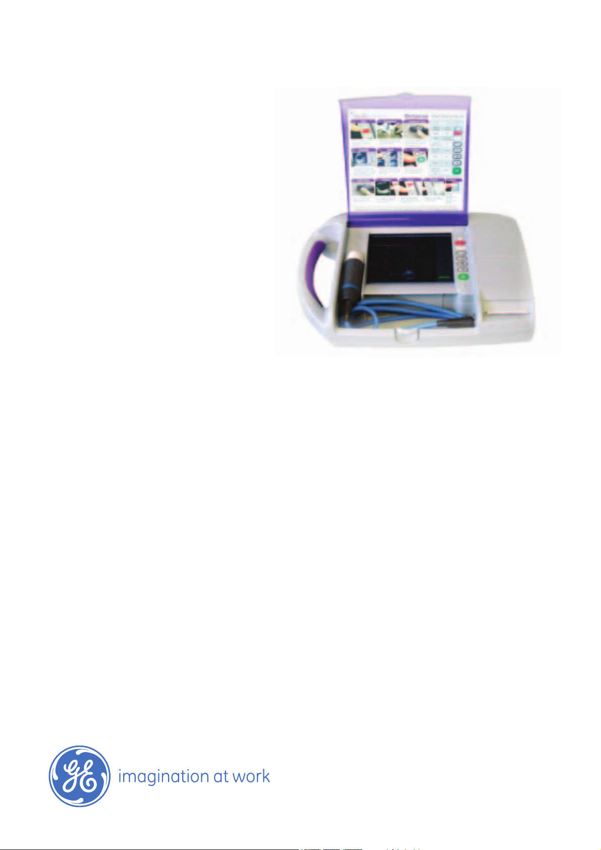
Portascan complete. . . . . . . . . . . . . . . . . . . . . . . . . . . . . . . . . . . . . . . . . . . . . . . . . . . . . . . . . . . . . . . . . . . . . . . . . . 5
Figure 6
Battery release & removal. . . . . . . . . . . . . . . . . . . . . . . . . . . . . . . . . . . . . . . . . . . . . . . . . . . . . . . . . . . . . . . . . . . . 5
Figure 7
Unscrew 4 screws ... & remove cover. . . . . . . . . . . . . . . . . . . . . . . . . . . . . . . . . . . . . . . . . . . . . . . . . . . . . . . . . . 5
Figure 8
Battery Pack & PCB Board. . . . . . . . . . . . . . . . . . . . . . . . . . . . . . . . . . . . . . . . . . . . . . . . . . . . . . . . . . . . . . . . . . . . 5
Figure 9
Back Panel with release screws arrowed. . . . . . . . . . . . . . . . . . . . . . . . . . . . . . . . . . . . . . . . . . . . . . . . . . . . . . 5
Figure 10
Note location of long screw. . . . . . . . . . . . . . . . . . . . . . . . . . . . . . . . . . . . . . . . . . . . . . . . . . . . . . . . . . . . . . . . . . . 5
Figure 11
Probe connector lock nut. . . . . . . . . . . . . . . . . . . . . . . . . . . . . . . . . . . . . . . . . . . . . . . . . . . . . . . . . . . . . . . . . . . . . 5
Figure 12
Use special Lemo wrench to loosen probe connector nut. . . . . . . . . . . . . . . . . . . . . . . . . . . . . . . . . . . . . .5
Figure 13
Cut or remove security sticker then hinge top away to separate case. . . . . . . . . . . . . . . . . . . . . . . . . . 5
Figure 14
The bottom case and handle grip can be placed to one side. . . . . . . . . . . . . . . . . . . . . . . . . . . . . . . . . . . 5
Figure 15
Two screws hold the main assembly in place. . . . . . . . . . . . . . . . . . . . . . . . . . . . . . . . . . . . . . . . . . . . . . . . . 5
Figure 16
Lift main board peeling away earth strap & disconnect plugs/skts. . . . . . . . . . . . . . . . . . . . . . . . . . . . . . 5
Figure 17
Note location of sounder & fan ... and display inverter board. . . . . . . . . . . . . . . . . . . . . . . . . . . . . . . . . . . 5
Figure 18
Carefully turn over main panel. . . . . . . . . . . . . . . . . . . . . . . . . . . . . . . . . . . . . . . . . . . . . . . . . . . . . . . . . . . . . . . . 5
Figure 19
Shielding removed. . . . . . . . . . . . . . . . . . . . . . . . . . . . . . . . . . . . . . . . . . . . . . . . . . . . . . . . . . . . . . . . . . . . . . . . . . . . 5

Table of Figures
Mediwatch Service Department
Service Documentation
Figure 20
Probe interface panel set. ... Remove screws to separate. . . . . . . . . . . . . . . . . . . . . . . . . . . . . . . . . . . . . . . 5
Figure 21
Separate ribbon connector, or carefully hinge probe interface boards . . . . . . . . . . . . . . . . . . . . . . . . . . 6
Figure 22
... to reveal ETX Heatsink screws. Retain Heatsink from other side. . . . . . . . . . . . . . . . . . . . . . . . . . . . . . 6
Figure 23
The compact flash can now be removed, reprogrammed & replaced. . . . . . . . . . . . . . . . . . . . . . . . . . . 6
Figure 24
RAM can also be accessed if necessary. (Observe E.S.D. precautions) . . . . . . . . . . . . . . . . . . . . . . . . . . . 6
Figure 25
Thermal Printer PCB … and location. . . . . . . . . . . . . . . . . . . . . . . . . . . . . . . . . . . . . . . . . . . . . . . . . . . . . . . . . . . 6
Figure 26
Paper roll installed. . . . . . . . . . . . . . . . . . . . . . . . . . . . . . . . . . . . . . . . . . . . . . . . . . . . . . . . . . . . . . . . . . . . . . . . . . . . 6
Dual Frequency prove & connector. . . . . . . . . . . . . . . . . . . . . . . . . . . . . . . . . . . . . . . . . . . . . . . . . . . . . . . . . . . . . 6
Rear panel connections. . . . . . . . . . . . . . . . . . . . . . . . . . . . . . . . . . . . . . . . . . . . . . . . . . . . . . . . . . . . . . . . . . . . . . . . 6
Bottom case label. . . . . . . . . . . . . . . . . . . . . . . . . . . . . . . . . . . . . . . . . . . . . . . . . . . . . . . . . . . . . . . . . . . . . . . . . . . . . 6
Keypad membrane. . . . . . . . . . . . . . . . . . . . . . . . . . . . . . . . . . . . . . . . . . . . . . . . . . . . . . . . . . . . . . . . . . . . . . . . . . . . 6

Section 1
1
Mediwatch Service Department
Service Documentation
About this manual
Chapter 1. Introduction
This service manual can be used to service the Portascan at board level. The manual explains the functioning of the boards by
means of functional block diagrams and photographs while connections can be checked at the connector overview.
Preventative and corrective maintenance is also included as are circuit diagrams.
Warnings
Chapter 2. Warnings and Precautions
A probe may only be connected to or disconnected from the scanner while the instrument is switched off. Ignoring
this may cause severe damage to your scanner and/or probe.
To avoid a risk of explosion the equipment must not be operated in the presence of flammable anaesthetics.
To avoid a risk of electric shock do not open the equipment. Refer servicing to qualified personnel only.
Be careful not to place the patient into contact with the ultrasound equipment or other devices. If the ultrasound
equipment or other devices are defective, there is a risk of electrical shock.
For continued protection against fire hazard, replace fuses only with the same type and rating.
The use of non-Mediwatch Plc components with this scanner may result in damage to Mediwatch Plc components.
To prevent hazards; refer to your local requirements for adequate electrical installation in case of class 1 type BF
equipment.
Do not subject the equipment to excessive shock, for example, when moving the equipment. If the equipment is
repeatedly subjected to excessive shock, mechanical parts may be damaged.
Assembly operations, extensions, re-adjustments, modifications or repairs must be carried out by authorized persons.
The electrical installation of the relevant room must comply with the IEC requirements.
The product must be used in accordance with the instructions for use.
Precautions
Cleaning the probe is done by first removing the ultrasound coupling gel with a soft tissue and then gently wipe the
probe dry using a new tissue or dry cloth.
When more cleaning is required only a mild detergent or hand-soap may be used together with some water and a
soft tissue cloth.
To avoid possible damage, the probe cable must not be coiled to a diameter of less than 9 cm (3.5 inch).
Although there is no danger to a patient with an implantable pulse generator (IPG); ultrasonic scanning equipment
could cause mechanical damage to the IPG if used directly over the device's implant site.
Do not use the equipment in locations subject to intense electric or magnetic fields (near transformers, for
example). If the equipment is used in such locations, the monitor will be adversely affected.
Do not use the equipment near devices generating high frequencies (such as medical telemeters and cordless
telephones). If used near such devices, the equipment may malfunction or adversely affect such devices.
To guarantee proper unit operation; do not operate the scanner in an environment with a temperature in excess of
35 °C. If the equipment is used in a small room, the room temperature may rise. Proper ventilation must be
provided.
Avoid installation near a heater or in direct sunlight .
For correct image geometry, only monitors properly adjusted by the manufacturer may be used on the scanner.
Inspect the probe carefully after a drop. A dangerous situation may arise due to damaged insulation of the probe
surface.
To prevent damage to mechanical probes due to excessive heat, a warning mechanism has been built into the system.

Section 1
2
Mediwatch Service Department
Service Documentation
Chapter 3. Technical Specifications of the Scanner
General Specifications:
Power Input 10 - 13.5 Vdc
Power Consumption 12 VA
Scanning Method Mechanical Sector
Display Modes B - mode
Probe Frequency 3.5/5.0 MHz
Max Image Depth 20 cm
Scan Converter Full Digital 512 x 512 x 8
Bladder Volume 0 -1500 ml
Accuracy 0 - 699 ml ± 20%, ± 20ml
(whichever is700 ml - 1500ml ± 25% ± 25ml greater)
Accuracy is based upon usage as per instructions and scanning a tissue equivalent phantom
Display Format 8 inch colour TFT LCD 640 x 480 pixels
Battery 12 Volt rechargeable at least 1.5 Hrs continuous operation
from full charge.
Dimensions WxDxH = 16 x13 x 13 cm
Weight 2540g without battery and probe3220g with battery and probe
Enclosure Leakage and Earth Leakage Current Within specification for Class II type BF according to
EN 60601 - 1
Environmental Operating Conditions Temperature 8 - 40ºC Humidity up to 90% (20ºC)
General Storage Conditions Temperature 0 - 50ºC
Standards EN 60601 - 1 & Class II, Type BF handheld equipment
Acoustic Output information for the 3.5/5.0 MHz Mechanical sector (410047):
Parameter: Mode B W o max.
P_ (MPa) 1.2
1spt (mW.cm2) 2.8
System settings 5.0HMz
Min. scan angle
Min. scan depth
1p 53.8
(mm)
Wpb6 (_1_) (mm) 2.4
Prr (KHz) 1708
Srr
(Hz) 2.8
Output Beam Dimensions 520.6
Area
(mm²)
Ø,< (mm), 19.35
(º)
Fawf (MHz) 3.2
Acoustic power up fraction 0
(%)
Maximum Power 2.6
(mW)
lob 0.6
(mW/cm²)
Power up mode B
Initialisation mode B
Acoustic output freeze YES
L tt 7.29
(mm)
Lts CONTACT
(mm)
Inclusive modes B
 Loading...