

Page 1
GE Healthcare
Lunar
enCORE-based X-ray Bone Densitometer
User Manual
Revision 5 - Part number: LU43616EN
Jan-2010
GE Medical Systems LUNAR Contact Numbers
Headquarters
GE Medical Systems Lunar
3030 Ohmeda Dr.
Madison, WI 53718
USA
+1 (800) 437-1171
China
No. 19 Changjiang Road
Wuxi, Jiangsu, 214028
P.R.C.
+86-510-85225888
+86-510-85226688 (fax)
www.gehealthcare.com
DPX Series YZB/USA 2099
Prodigy Series YZB/USA 0509
iDXA YZB/USA 1104-2007
Operator's Manual for DPX-NT, DPX-MD+, DPX Bravo, DPX Duo, Prodigy, Prodigy Advance, Prodigy Primo, and Lunar iDXA x-ray bone densitometers
systems using enCORE with Windows XP Professional computers. GE Healthcare recommends viewing the instructions for navigating the Lunar
enCORE™ based X-ray Bone Densitometer User Manual before proceeding through the online guide for the first time. Before operating scanner,
read the Safety and Technical Specifications manual which is part of operator's instructions.
SFDA(I) 20023301115
SFDA(I) 20043301375
SFDA(I) 20073302084
GE Medical Systems IT GmbH
Munzinger Strasse 3-5
D-79111 Freiburg, Germany
+49 212 2802 652
+49 0761 45 43 233 (fax)
France
11 Avenue Morane Saulnier
78 457 VELIZY
+33-1-34-49-5365
+33-1-34-49-5406 (fax)
DPX-Bravo SFDA Register Number:
Production License Number:
Product Standard Number:
Production & Registration Address:
Service Address:
Postal Code:
Contact Phone:
Germany
Beethoven Str. 239
D-42655 Solingen
Germany
+49-212-2802-0
+49-212-2802-390 (fax)
Asia/Pacific
4-7-127 Asahigaoka
Hino-shi, Tokyo 191-8503
Japan
+81-42-585-5111
+81-42-585-3077 (fax)
JSFDA(I) 2009 No.2300674
YZB/苏0637-2009
苏食药监械生产许2001-0041号
No.19 Changjiang Road, Wuxi National Hi-Tech
Development Zone, Jiangsu P.R.China
GE Medical Systems Trade Development
Corporation (Shanghai) Co.,Ltd
3 floor, CTP1 building,
No1. Huatuo Road
ZhangjiangGaoke, Shanghai
201203
8008108188
Page 2

Table of Contents
Introduction ................................................................................................................. 7
Intended Use ....................................................................................................... 7
Device Descriptions ............................................................................................ 7
Installation and Operation ................................................................................. 11
1.0 Screens and Toolbars ....................................................................................... 14
1.1 Overview ..................................................................................................... 14
1.2 Main Screen ............................................................................................... 15
1.3 Analyze Screen .......................................................................................... 16
1.4 Directory Screen ........................................................................................ 18
1.5 New Measurement Screen ........................................................................ 20
1.6 Quality Assurance screen .......................................................................... 23
1.7 Options ....................................................................................................... 24
2.0 Quality Assurance .............................................................................................. 34
3.0 Measurement .................................................................................................... 37
3.1 Measurement Overview & Warnings .......................................................... 37
3.2 Measurement Procedures .......................................................................... 38
3.3 Pediatrics Option ....................................................................................... 53
3.4 OneScan .................................................................................................... 53
3.5 OneVision Feature ..................................................................................... 55
3.6 Orthopedic Hip Option ............................................................................... 56
3.7 Quick View .................................................................................................. 58
3.8 Spine Phantom Procedure .......................................................................... 58
4.0 Analysis Procedures ........................................................................................... 60
4.1 Basic analysis procedures ......................................................................... 61
4.2 AP Spine Analysis ...................................................................................... 64
4.3 APVA Morphometry Analysis ..................................................................... 66
4.4 APVA Spine Geometry Analysis ................................................................ 66
4.5 Femur/ DualFemur Analysis ....................................................................... 68
4.6 Advanced Hip Analysis ............................................................................... 69
4.7 Total Body Analysis.................................................................................... 73
4.8 Composition Analysis ................................................................................. 75
4.9 Lateral Spine Analysis ............................................................................... 85
4.10 LVA Morphometry Analysis ....................................................................... 86
4.11 LVA Spine Geometry Analysis .................................................................. 93
4.12 Forearm Analysis ..................................................................................... 94
4.13 Hand Analysis .......................................................................................... 96
4.14 Orthopedic Analysis .................................................................................. 97
4.15 Pediatric Analysis ...................................................................................... 98
4.16 Small Animal Body Analysis ................................................................... 101
4.17 Custom Reference Population ................................................................ 103
4.18 ScanCheck™ ......................................................................................... 104
4.19 Practice Management Tools .................................................................. 106
4.20 Composer Reports ................................................................................. 110
4.21 DXA Results Report ................................................................................ 114
4.22 Precision Calculator ................................................................................ 118
4.23 Custom Analysis .................................................................................... 120
4.24 FRAX* 10-Year Fracture Risk ................................................................. 122
5.0 Database Maintenance .................................................................................... 124
5.1 Maintenance Procedures .......................................................................... 125
5.2 Compress Database ............................................................................... 125
5.3 Delete Database ..................................................................................... 126
5.4 Edit Database ......................................................................................... 126
5.5 New Database ....................................................................................... 127
5.6 Archive .................................................................................................... 128
Page 2 of 138
Page 3

5.7 Rebuild Database................................................................................... 128
5.8 Database Importing ................................................................................... 129
5.9 Move ....................................................................................................... 131
5.10 Copy exam file ...................................................................................... 132
5.11 Change Image Type ............................................................................. 133
5.12 Delete patient and Delete image ........................................................... 133
5.13 Edit Patient and Edit Image .................................................................. 134
5.14 External USB Hard Drive ........................................................................ 134
5.15 SQL Database Interface ......................................................................... 134
5.16 Task Scheduler ....................................................................................... 137
5.17 Batch Exam File Operations ................................................................... 137
Index ....................................................................................................................... 138
Page 3 of 138
Page 4

Caution: United States Federal law restricts this device to sale by or on the order of a licensed physician.
This is required per 21CFR801.109 (code of federal regulations). The information in this manual is subject to change without notice.
You may use or copy the software described in this manual only in accordance with the terms of your software license, product
warranty, or service contract agreements. No part of this publication may be reproduced for any purpose whatsoever, stored in a
retrieval system, or transmitted in any form or by any means, mechanical, photocopying, recording or otherwise, without the express
written permission of GE Medical Systems Lunar.
GE Medical Systems Lunar makes no warranty of any kind with regard to this material, and shall not be held liable for errors
contained herein or for incidental or consequential damages in connection with the furnishings or use of this manual.
Read this manual thoroughly before using the system or attempting to service any components. Unauthorized service may void
system warranties or service contracts. Consult GE Medical Systems Lunar Support before attempting any service: 800-437-1171.
LUNAR is a registered trademark of GE Medical Systems Lunar. All other product and brand names are registered trademarks or
trademarks of their respective companies.
Copyright© 1999, 2000, 2001,2002, 2003,2004,2005, 2006, 2007, 2008, 2009, 2010
GE Medical Systems Lunar, Madison, Wisconsin. All rights reserved.
Software License Agreement and Limited Software Warranty
Please carefully read the following terms and conditions before installing or operating the GE Medical Systems Lunar Software
("Software"). By installing or using the Software in your GE Medical Systems Lunar product, You indicate your acceptance of these
terms and conditions. If You do not agree with the terms and conditions, do not install or operate the Software and return it to GE
Medical Systems Lunar. The Software has been provided to You for use on a specific GE Medical Systems Lunar product. The
Software is provided under the terms of this Agreement and is licensed to You, not sold. Your rights to use the Software are subject
to the terms and conditions contained within this License Agreement and GE Medical Systems Lunar reserves any rights not
expressly granted to You. This License is non-exclusive and a non-transferable license to use the GE Medical Systems Lunar
Software. Re-distribution of Software or any documentation provided to you by GE Medical Systems Lunar is strictly prohibited. This
product includes some software components that are licensed under the GNU General Public License (GPL). Source code for GPL
components is available upon request.
The terms and conditions of this License Agreement and Limited Software Warranty are as follows:
1. LICENSE. This License allows You to:
(a) use the Software on a product in accordance with the accompanying documentation.
To "use" the Software means that the Software is either loaded in the temporary memory
of a computer or installed on any permanent memory or media of a computer (e.g.,
hard disk, CD-ROM, optical disk, zip disk, and the like);
(b) make one (1) copy, in machine-readable form, of the Software as provided to
You solely for the purposes of backup; provided that such copy includes the reproduction
of any copyright notice or other proprietary notice appearing in or on such Software.
2. LICENSE RESTRICTIONS.
(a) YOU MAY NOT, EXCEPT AS EXPRESSLY PROVIDED FOR IN THIS LICENSE: (i) DECOMPILE, DISASSEMBLE, OR
REVERSE ENGINEER THE SOFTWARE (except to the extent applicable laws specifically prohibit such restriction); (ii)
COPY, MODIFY, ADAPT, TRANSFER, TRANSLATE, RENT, LEASE, GRANT A SECURITY INTEREST IN, OR LOAN THE
SOFTWARE OR ANY PORTION THEREOF; (iii) CREATE DERIVATIVE WORKS BASED UPON THE SOFTWARE OR
ANY PORTION THEREOF; OR (iv) REMOVE ANY COPYRIGHT OR PROPRIETARY NOTICES OR LABELS IN OR ON
THE SOFTWARE.
(b) You understand that GE Medical Systems Lunar may update or revise the Software, and in so doing incur no obligation
to furnish such updates to You under this License. GE Medical Systems Lunar has no obligation to improve, update or
support the Software in the future.
(c) In the event the instrument or product designated for the Software is sold or otherwise transferred to a third party, that
party is not authorized to use the Software unless they first pay to GE Medical Systems Lunar the applicable license fee and
agree to the terms and conditions of a Software License Agreement. Upon transfer of the Software or any copy thereof, the
License granted hereunder shall terminate immediately.
3. TERM AND TERMINATION.
This License is effective until terminated. This License will terminate immediately without notice from GE Medical Systems Lunar or
judicial resolution if You fail to comply with any provision of the License. Upon any termination of this License, You agree to return or
destroy the Software, all accompanying written materials and all copies thereof in any form. Section 5 will survive any termination.
4. EXPORT LAW.
You agree that neither the Software nor any direct product thereof is being or will be shipped, transferred or re-exported, directly or
indirectly into any country prohibited under United States law or regulations promulgated thereunder.
5. WARRANTY.
GE Medical Systems Lunar warrants that, to the best of our knowledge, the software provided with this License will perform as
described in the product's operator's manual and the technical specification for this Software. This limited warranty is contingent
upon proper use of the Software and does not cover any Software which has been modified, subjected to malicious logic, unusual
physical or electrical stress, or used on computer equipment not specified by GE Medical Systems Lunar.
GE Medical Systems Lunar does not warrant that the functions contained in this Software will meet your requirements, or that the
operation of the Software will be uninterrupted or error- free. Statements made about this Software do not constitute warranties and
shall not be relied upon by You in deciding whether to purchase the GE Medical Systems Lunar product or use the Software. IN NO
EVENT SHALL GE HEALTHCARE BE LIABLE TO YOU FOR ANY DAMAGES ARISING OUT OF THE USE OR INABILITY TO
USE SUCH SOFTWARE.
THE SOLE AND EXCLUSIVE REMEDY IN THE EVENT OF DEFECT IS EXPRESSLY LIMITED TO THE REPLACEMENT OF THE
SOFTWARE PROVIDED. IF FAILURE OF THE SOFTWARE HAS RESULTED FROM ACCIDENT OR ABUSE, GE MEDICAL
Page 4 of 138
Page 5

SYSTEMS LUNAR SHALL HAVE NO RESPONSIBILITY TO REPLACE THE SOFTWARE. GE Medical Systems Lunar will
consider this warranty to be void if You fail to comply with the terms in the Software License Agreement.
6. TITLE.
Title, ownership rights, and intellectual property rights in the Software shall remain with GE Medical Systems Lunar. This Software is
protected by the copyright laws and treaties.
7. MISCELLANEOUS.
This Agreement represents the complete agreement concerning this License and may be amended only by a writing executed by
both parties. The License is governed by the laws of the State of Wisconsin, U.S.A. without regard to its conflict of laws principles. If
any provision of this Agreement is held by a court of competent jurisdiction to be unenforceable, that provision shall be enforced to
the maximum extent permissible and/or reformed only to the extent necessary to make it enforceable, and the remaining provisions
of this Agreement will not be affected or impaired in any way. If any legal action or proceeding is brought for the enforcement of this
Agreement, or because of any alleged dispute, breach, default or misrepresentation in connection with any of the provisions of this
Agreement, the successful or prevailing party shall be entitled to recover reasonable attorneys' fees and other costs incurred in such
action or proceeding, in addition to any other relief to which such party may be entitled.
This product includes some software components that are licensed under the GNU General Public License (GPL). Source code for GPL
components is available upon request.
General Product Information
The bone densitometer is designed to estimate the bone mineral density of patients when medically indicated by their physicians. The
manuals provide instructions for operating the software and scan table, system information, and maintenance information.
Variables Affecting Scan Results
Scan results can be affected by operator technique and patient variability:
• Operator technique refers to patient positioning and scan analysis. To minimize technique variables, 1) establish consistent
positioning and scan analysis routines by using anatomical landmarks when positioning patients, and 2) during analysis,
manipulate raw scan data only when absolutely necessary.
• Patient variability refers to changes in the patient's medical history, metabolism, and diet. It also refers to diagnostic procedures
that involve radionuclide uptake and medical treatment, and the presence of external radiation (particularly the use of other
radiation-generating devices in the vicinity of the system). To minimize patient variability, 1) thoroughly familiarize yourself with
the patient's history, and 2) install the scanner in an environment effectively shielded from other sources of external radiation.
United States Federal Law restricts this device to the sale, distribution, and use by or on the order of a physician.
Operator Profile
The intended users of the DXA scanner are medical professionals with knowledge and experience required to work with x-ray
equipment.
Training Information
GE Medical Systems Lunar or authorized GE Medical Systems Lunar distributors provide individual, hands-on training as part of the
installation procedure for your system. (GE Medical Systems Lunar distributors provide training for systems installed outside the United
States.) An Applications Specialist provides information on software and hardware operations, and reviews the warnings and cautions
in the manuals.
IMPORTANT: Only trained technologists should operate the system. New technologists should receive training prior to
unsupervised operation of the system. Additional training sessions are available on request for a nominal fee. For more
information, contact GE Medical Systems Lunar Support at 800-334-5831, or your local GE Medical Systems representative.
Cautions for DXA Determinations
You should be aware of the following factors which may affect the clinical accuracy of DXA spine estimates: marked distortions of
skeletal architecture-e.g., osteophytes, degenerative disc disease, spinal arthritis, spondylolisthesis, kyphoscoliosis, and vertebral
fractures-and significant calcium deposits in the aorta can falsely elevate spine bone mineral values. Regions that contain these
dystrophic calcifications can be excluded from the scan analysis in some cases. The scanner can be used to monitor changes in bone
mineral over time in patients with these disorders, but caution must be taken in interpretation. Use DXA estimates as an aid to other
methods in the evaluation of patient bone mineral status in the clinical setting.
In addition, spine estimates will be difficult to interpret for patients with orthopedic metal devices and previous surgical interventions,
such as bone grafts. Radiographic contrast material and radiopharmaceuticals used for myelograms, barium enemas, and other
diagnostic tests prevent accurate estimates. Barium clears the body within a few days, but the oil-based dyes used in myelograms
several years ago may remain within the body for years. A three-day waiting period is sufficient time for barium and most
radiopharmaceuticals to be completely discharged from the body.
Femur estimates will be difficult to interpret for patients with orthopedic metal devices and previous surgical interventions. The most
common complicating factors for femur estimates are prosthetic devices and surgical implants in the region of the bone scan. Results
may be adversely affected if the patient has difficulty with the desired 25° inward rotation of the leg or with maintaining this position
without movement.
Total Body estimates require consistent patient positioning for accurate results and will be difficult to interpret for patients with
orthopedic metal devices and previous surgical interventions. The operator should pay particular attention to the location of the patient's
arms, keeping the positioning the same for each scan. Results may be affected if the patient moves during the scan.
Precautions for Standard Operating Procedures
• Do not attempt to operate the scanner without first reading this manual.
• Do not remove the assembly panels or attempt any repairs without prior instructions from authorized GE Medical Systems
Lunar personnel.
• Do not sit or lie on the scan table for purposes other than scanning.
• Perform the Quality Assurance procedure each morning. If any test fails, check the position of the calibration block and rerun
the QA procedure. If a test fails again, contact GE Medical Systems Lunar Support. Also, call GE Medical Systems Lunar if
more than two failures occur in a one-week period.
Page 5 of 138
Page 6

• If the patient is or might be pregnant, always contact the patient's physician before performing a scan.
• Remain in the room with the patient while a scan is in progress.
• Restrict access to the room to authorized personnel.
• Do not attempt to service any of the system's electrical components while the scan table is turned ON. High voltage is used to
produce x-rays.
• Radiation safety information is located in the safety and technical specifications manual you received with your system.
• To stop the scanner in an emergency, press the emergency stop button on the scan arm. DO NOT use the emergency stop
button to routinely abort a scan.
Software Installation
If loading software, you will be asked for your system number and feature code during the installation procedure. These numbers are
printed on the CD sleeve. Put the CD in the CD-ROM drive. When the Installation window appears, select the product software option.
Follow the screen prompts to install the program. The software will attempt to install validated Microsoft Security updates on all U.S.
computers before installing the product software. This may take up to 45 minutes. The Help disk (second disk) contains Help Topic
documents in PDF format for printing. You will need Adobe Acrobat Reader to open PDF documents.
Note: If the CD does not automatically start, select the My Computer icon on the desktop, select the CD-ROM drive, and select the
software installation icon.
Page 6 of 138
Page 7

Introduction
Intended Use
The X-ray Bone Densitometer (DPX-Bravo, DPX-Duo, DPX-NT, Prodigy, iDXA) supports the following intended
use:
Provides an estimate of bone mineral density at various anatomical sites (Spine, Femur, Total Body, and Forearm).
These values can then be compared to an Adult reference population at the sole discretion of the physician.
Provides an assessment of relative fracture risk based on the patient's T-score value using the categories of
fracture risk defined by the World Health Organization (WHO).
Provides an assessment of 10-year fracture risk using WHO FRAX model.
Provides a standardized bone density report using data from the densitometer and physician- generated
assessments based on the patient's demographics, which can assist the physician in communicating scan results
to the patient and the patient's referring physician.
Optional Hand BMD software estimates the BMD at the hand.
Optional Dual-Energy Vertebral Assessment software provides an x-ray image of the spine for qualitative visual
assessment in order to identify vertebral deformations and estimate vertebral heights (morphometry).
Optional Orthopedic Hip Software estimates Periprosthetic BMD of an orthopedic hip implant
Optional Pediatric software option expands the range of bone densitometry reference data to include ages 5
through 19 years of age. The software provides a comparison of measure variables obtained by dual energy x-ray
absorptiometry to a database of reference values. These data can be used for comparative purposes at the sole
discretion of the physician.
Optional Body Composition software measures the regional and whole body bone mineral density (BMD), lean and
fat tissue mass and calculates other derivative values which can be displayed in user-defined statistical formats and
trends, and compared to reference populations at the sole discretion of the health care professional. Some of the
diseases/conditions for which body composition values are useful include chronic renal failure, anorexia nervosa,
obesity, AIDS/HIV and cystic fibrosis.
Optional Advanced Hip Assessment Software provides a measurement of hip axis length (HAL) and a mean value
of HAL for Caucasian and Asian females on femur images. It also calculates hip geometry val ues used to evaluate
the structural properties of the hip.
The DPX-Duo model has special mechanical features including stirrups, storage dra wers, and patient step to allow
use as an exam table when bone densitometry is disabled and the scan arm is rotated and locked parallel to the
table.
Device Descriptions
Structure
The X-Ray Bone Densitometer is made up of a scan arm, X-ray source assembly, and exam table. Each
model is described in more detail below. The scan arm control panels for each model are described in scan
arm control panel section.
Product Model
DPX Bravo and Duo
Page 7 of 138
Page 8
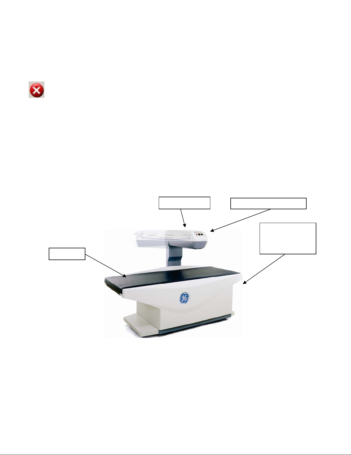
The DPX Bravo and Duo models use pencil beam technology with a single-crystal detector and have a
compact table design to provide space efficiency (see images below).
The DPX Duo and the DPX Bravo come equipped with a scan arm that swings to the side of the table when not
in use when not in use as a densitometer and to facilitate patient loading. X-ray scanning is not possible until
the scan arm is locked into the scan position. A handle releases the scan arm interlock and allows operator to
move the scan arm for patient loading. Once the patient is loaded on the table, the operator moves the scan
arm back to scanning position and the arm locks into scan position. If a scan is attempted without the scan arm
locked into position, the following error will be displayed:
Error Description:
Swing arm not locked in scanning position. Please lock before continuing.
Corrective Action:
Please try again. If the problem persists, contact GE Lunar Support for assistance.
To retract the scan arm once the scan is completed, home the scan arm.
Pull the lever on the front of the scan arm towards you and push the scan arm to the left until it rests along the
back of the scanning table. The patient can then sit up and the table is free of obstruction.
The power switch is located at the head of the table. There is also a roll at the head of the table to store up to
21” x 3” (53.34 cm x 7.62 cm) exam paper. The table weight limit is 159 kg (350 pounds).
Swing Scan Arm
Scan Arm Control Panel
Exam Paper Roll
and Power Switch
(head of scanner-not shown)
Table Pad
DPX-Bravo
The DPX-Duo model also has mechanical features including stirrups, procedure drawer, storage drawers, and
patient step to allow use as an exam table when bone densitometry is disabled and the scan arm is rotated and
locked parallel to the table.
Page 8 of 138
Page 9
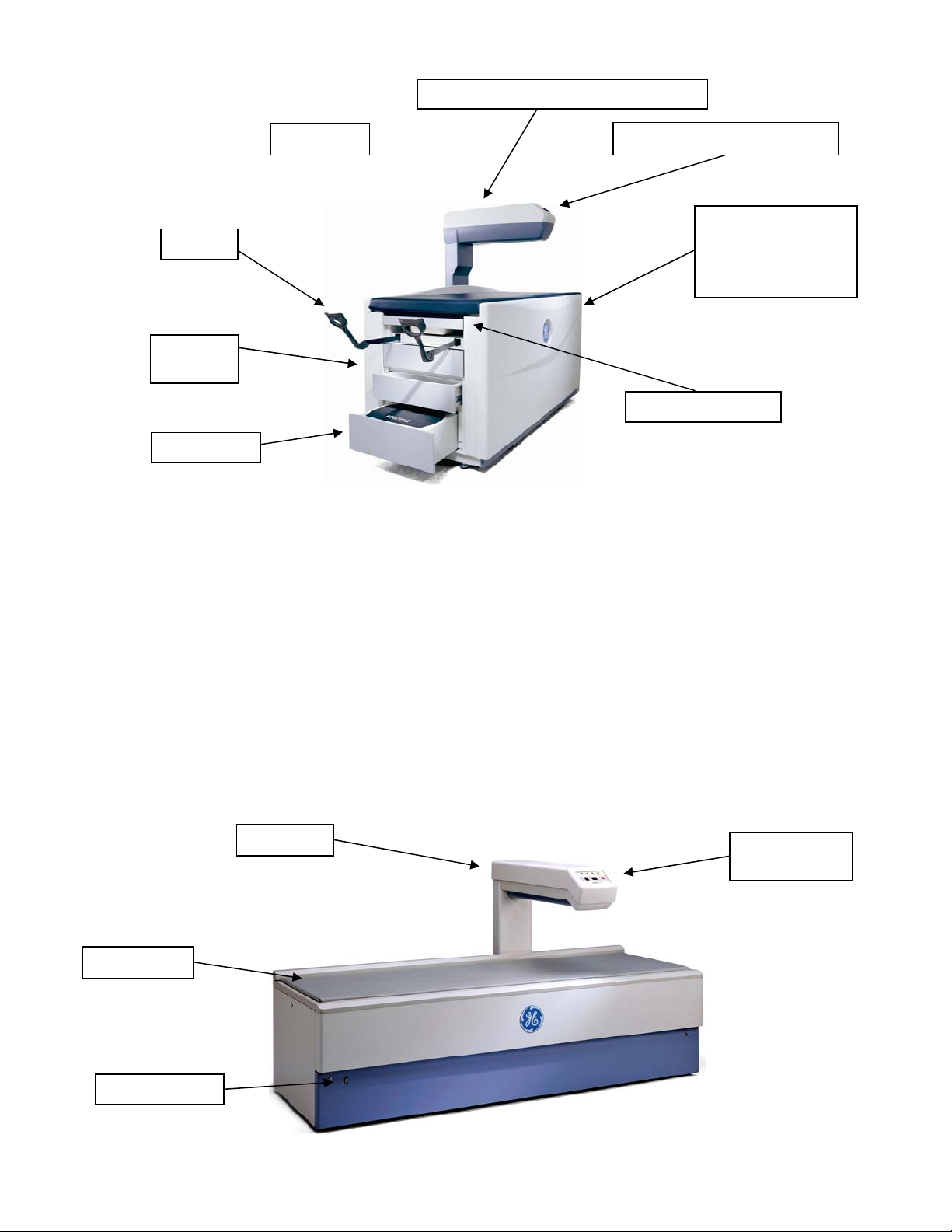
Stirrups
Storage
Drawers
Patient Step
Table Pad
Swing Scan Arm (in scanning position)
Scan Arm Control Panel
Procedure Drawer
Exam Paper Roll
and Power Switch
(head of table--not
shown)
DPX-Duo
Product Model
DPX-Pro/NT/MD+
DPX-Pro/NT/MD+ models come in full and compact sizes and u se pencil beam technology with a single-crystal
channel NaI detector. The power switch is located on the lower front panel. The table weight limit is 136 kg
(300 lbs).
Scan Arm
Scan Arm
Control Panel
Table Pad
Power Switch
Page 9 of 138
Page 10
DPX-NT
Product Model
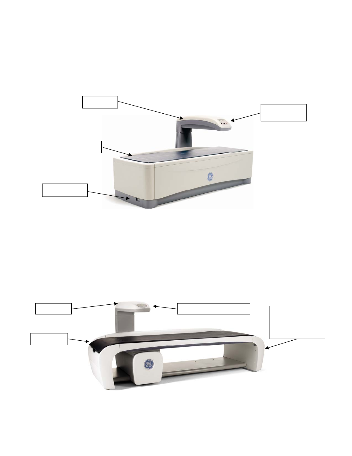
Prodigy Pro/Primo/Advance
Prodigy models come in full and compact sizes and use fan beam technology with a 16-channel solid-state
detector. The power switch is located at the foot of the scanner. The table weight limit is 159 kg (350 lbs).
Scan Arm
Scan Arm
Control Panel
Table Pad
Power Switch
Prodigy Series
Product Model
iDXA
The Lunar iDXA uses fan beam technology with a 64-channel solid-state detector and is a scanner designed for
optimal image quality and supports patient's weights to 204 kg (450 lbs).
The power switch and exam paper roll is located at the head of the scanner.
Scan Arm Scan Arm Control Panel
Exam Paper Roll
and Power Switch
(head of scanner-
-not shown)
Table Pad
iDXA
Page 10 of 138
Page 11
The Warning label identifies the location of possible pinch points. When the scanner arm is in motion, make sure
possible pinch point areas are clear at all times. The technologist must keep their feet away from the moving
carriage. Patient limbs must remain inside the boundaries of the table top to avoid a pinch between the scanner
arm and table.
Installation and Operation
Only individuals trained by GE Lunar should service or install the X-ray Bone Densitometer. Do not attempt to
service the X-ray Bone Densitometer. Please call GE service or your GE distributor for support.
Before operating X-ray Bone Densitometer, please review the Safety and Technical Specification manual.
X-ray Bone Densitometer Table Assembly
Below “Scanner” is equal to “X-ray Bone Densitometer”
Scanner Table
The Scanner table is to support the patient during a measurement or general examination. In addition, the X ray
source assembly and other electronics are contained inside the scanner table.
Scan Arm
The laser light, emitted from an aperture on the scanner arm, helps you locate the measurement start position.
Positioning switches let you move the scanner arm until the laser light is located at the correct start position.
The start position is different for each measurement type. The scanner arm on the DPX Duo and Bravo models
has a release and locking mechanism allowing the upper arm to swivel when the scanner is idle. The scanner
arm must be in the locked position over the scanner table to perform a measurement.
Scan arm control panel
Indicator Lights
Symbol Indicator Status (on)
Green (power) Power is supplied to the scanner table
Yellow (x-ray) X-ray tube assembly is supplying x-rays
Yellow (shutter) Shutter is open
Amber (laser) Laser is on
Page 11 of 138
Page 12
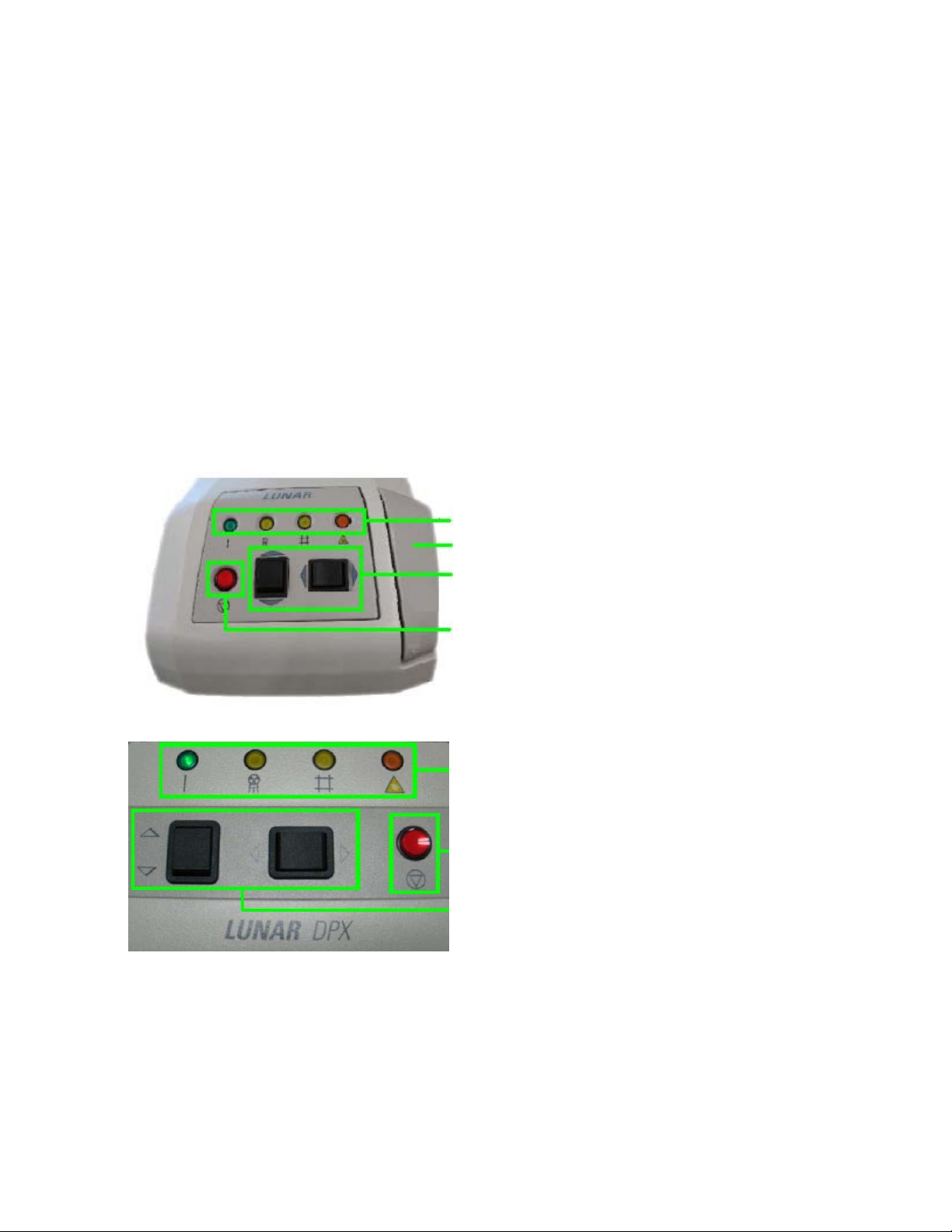
Emergency stop button
Push the red emergency stop button to stop the scanner arm and immediately shut down x-rays in an
emergency. Do not use the emergency stop button to routinely stop the scanner during normal operation.
Positioning switches
The positioning switches move the scanner arm and detector to the measurement start position (the lase r
light indicates the position of the detector). The Back/Front switch moves the detector across the width of
the scanner table. The Left/Right switch moves the scanner arm down the length of the scanner table.
Swing arm position sensing switches (DPX Duo and Bravo models only)
The swing arm position sensing switches detect the locking status of the swing arm and the swing arm
latch. The swing arm latch must be locked and the swing arm must be in the locked position over the scan
table before a measurement can be performed. Release of the swing arm latch during a measurement will
abort the scan and the measurement data will be lost.
Scanner Start button (iDXA model only)
Once the patient has been positioned, the scan may be initiated from the green Start Scan button instead
of starting the scan from the enCORE software.
See scan arm control panel for each model below:
Indicator Lights
Lever to lock/unlock Swing Arm
Positioning Switches
Emergency Stop Button
DPX Duo and Bravo
Indicator Lights
Emergency Stop Button
Positioning Switches
DPX-Pro/NT/MD+
Page 12 of 138
Page 13

Indicator Lights
Emergency Stop Button
Positioning Switches
Start Scanner Button
iDXA Front Panel
The enCORE software is used to operate the X-ray Bone Densitometer, the following chapters describe how
to use the enCORE software.
Note:
Daily Quality Assurance procedure
Complete quality assurance procedures daily. Make sure each QA procedure passes. Refer to Chapter 2
for detailed instructions. Make sure you save your printed results for future reference.
Archive image files
Archive your image files before you leave for the day. Refer to Chapter 5 for detailed instructions.
Shut down computer
At the end of the day, select Exit from the Main screen, and select Exit enCORE from the close window to
close the program. Then shut down the computer. Note: Do not turn off the scanner at the end of the day for
stationary systems.
Some of the functions of the enCORE are not available for all X-ray Bone Densitometer models.
Classifications
Protection against electric shock: Class I, Type B
Protection against water: IPX0
Operation mode: continuous operation with intermittent loading
The device can neither be used in flammable anesthetic mixture with air or non flammable anesthetic mixture
with oxygen or nitrous oxide.
Page 13 of 138
Page 14

1.0 Screens and Toolbars
1.1 Overview
1.2 Main Screen
1.3 Analyze Screen
1.4 Directory Screen
1.5 New Measurement Screen
1.6 Quality Assurance Screen
1.7 Options
1.1 Overview
This section describes the screens and toolbars that are shown throughout the program. Screens and toolbars
give the options necessary to complete the procedures given in this online Operator's Manual.
1.1.1 Using screens
The screens provide information that lets you set up and complete measurements, analysis, and quality
assurance procedures. At the bottom of each screen, short descriptions of procedures and alternative
keystrokes are given to help you complete a procedure.
1.1.2 Using toolbars
The toolbars show icons that represent a "tool" which lets you complete a specific procedure. To view a short
description of a tool, hold the cursor stationary over the tool's icon.
1.1.3 Patient block
The Patient block is shown at the bottom of the Analyze, Directory, and New Measurement screens. The
Patient block gives information about the patient that is being analyzed, measured, or is currently selected at
the Directory screen. This is the same information you record in the Patient Information dialog box or select
from the Patient list before starting a new measurement.
Page 14 of 138
Page 15
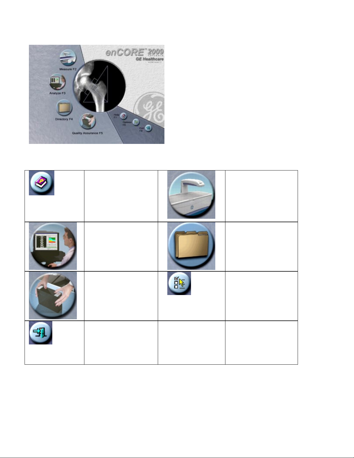
1.2 Main Screen
The Main screen is the first screen shown during the program. Select the options that follow to access different
areas of the program:
Help (F1)– select to
view additional
reference information
concerning the
operation of the
scanner.
Analyze (F3)–select to
open a patient
measurement for
analysis.
Quality Assurance
(F5)–select to access
the Quality Assurance
(QA) screen.
Exit (F8)–select to exit
the program from the
Main screen.
Measure (F2)–select to
start a patient
measurement.
Directory (F4)–select
to work with your
patient files and
complete database
maintenance
procedures.
Options (F6)–select to
change the User
Options and
Connectivity Options
default settings or to
view the Error log.
Page 15 of 138
Page 16
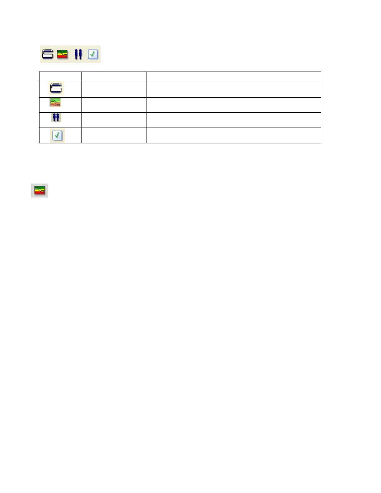
1.2.1 Common Toolbar
The Common Toolbar is shown on all screens.
Icon Program Description
Measure
(F2 or Ctrl+M)
Analyze
(F3 or Ctrl+A)
Directory
(F4 or Ctrl+D)
QA
(F5 or Ctrl+Q)
Select to enter patient information or select a patient from
the database to start a new measurement.
Select to choose an image file for analysis.
Select to work with patient files and complete database
maintenance procedures.
Select to start a Quality Assurance (QA) test.
1.3 Analyze Screen
The Analyze screen is used to analyze image files. This screen is shown when you select Analyze from
the Common toolbar or the main screen or when you select an image file for analysis from the Dire ctory screen.
In addition, this screen is shown immediately after a patient measurement if the "Analyze When Done" option is
selected at the New Measurement screen.
1.3.1 Results Tabs
The data that follows is included in the Results tabs for image files:
• ScanCheck™ tab–provides a checklist of items to confirm and/or correct during analysis
• Densitometr y tab–provides BMD, BMC, and Area for each region of the scan
• Trend tab–provides results trending over time
• Information tab–gives info rmation related to the scan parameters.
• Composition tab- Total Body composition or Spine/Femur estimated composition
• AHA ta b–Femur Advanced Hip Assessment, gives information about hip axis length and hip strength
results.
• Morphometry tab. (Refer to LVA analysis or APVA analysis for more information.)
1.3.2 Analyze toolbar
Select tools from the Analyze toolbar to complete analysis procedures. Refer to specific scan types for
detailed analysis recommendations for each measurement site.
Page 16 of 138
Page 17
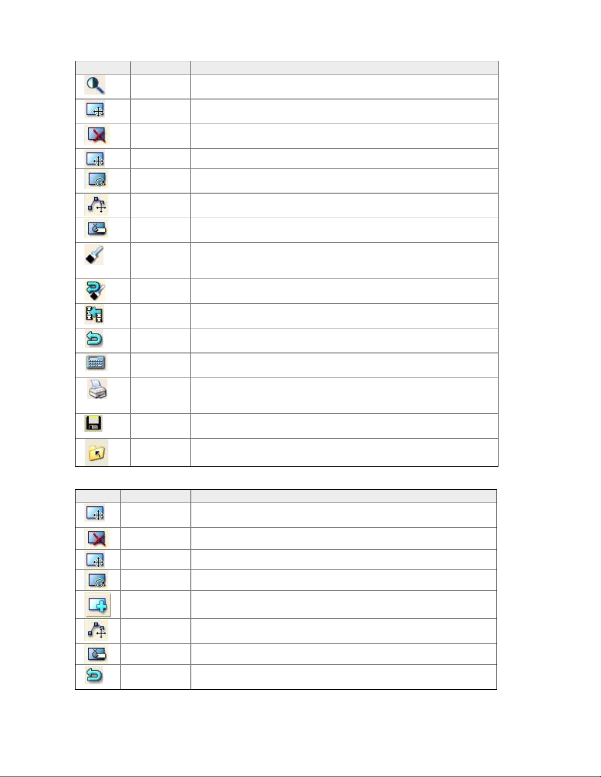
General Analysis Tools
Icon Tool Description
Imaging
(Ctrl+I)
ROIs
(Ctrl+R)
Delete
ROI
Move ROI
Select to adjust contrast and zoom the image file.
Select to position ROIs during analysis. Move and size ROI as well
Use this option to delete an ROI
This tool allows an ROI to be moved
Rotate
ROI
Move
Vertex
Label
ROIs
Points
(F4)
Select this tool to turn an ROI in a circular motion
Select this tool to move a vertex of an ROI
May be used to label an ROI.
Select to verify that bone and tissue samples are correctly classified.
DO NOT adjust point typing unless the program made obvious
errors.
This option is shown after you select Points. Select Reset to delete
changes you made to point typing.
Use this option to copy ROIs from an existing image file to the
current image file.
This option is shown after you select ROIs or Points. Select Cancel
to delete changes you made to the image file.
This option is shown after you select ROIs or Points. Select Results
to view analysis results for the image file.
Select to create analysis reports for the image file.
Reset
(F3)
Copy
(F5)
Cancel
(Esc)
Results
(Enter)
Report
(Ctrl+Shif
t+P)
Save
(Ctrl+S)
Close
(Esc)
Select to save the image file and data to the patient database.
Select to close the image file.
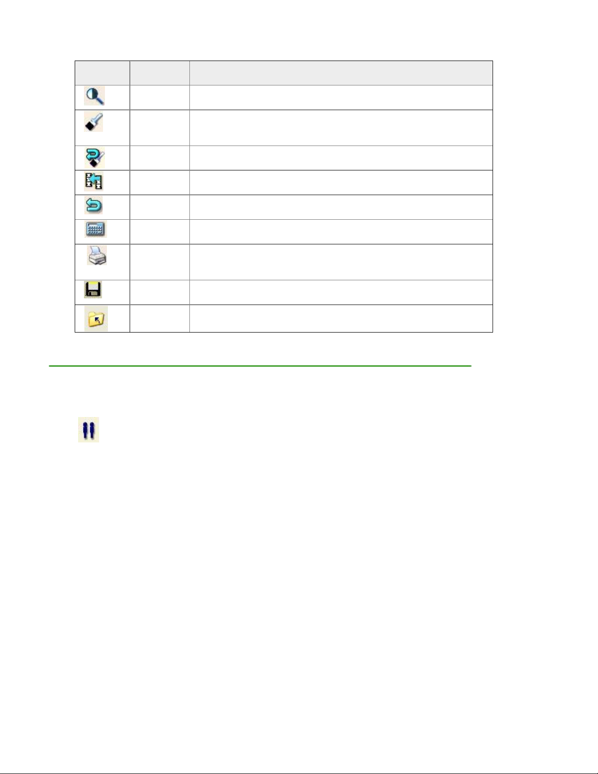
ROI Tools
Icon ROI Tool Description
ROIs
(Ctrl+R)
Delete ROI
Select to position ROIs during analysis. Move and size ROI as well
Use this option to delete an ROI
Move ROI
This tool allows an ROI to be moved
Rotate ROI
Select this tool to turn an ROI in a circular motion
Add ROI
AP Spine
Move
Vertex
Label ROIs
Select this tool to move a vertex of an ROI
May be used to label an ROI.
Cancel
(Esc)
This option is shown after you select ROIs or Points. Select Cancel
to delete changes you made to the image file.
Page 17 of 138
Page 18
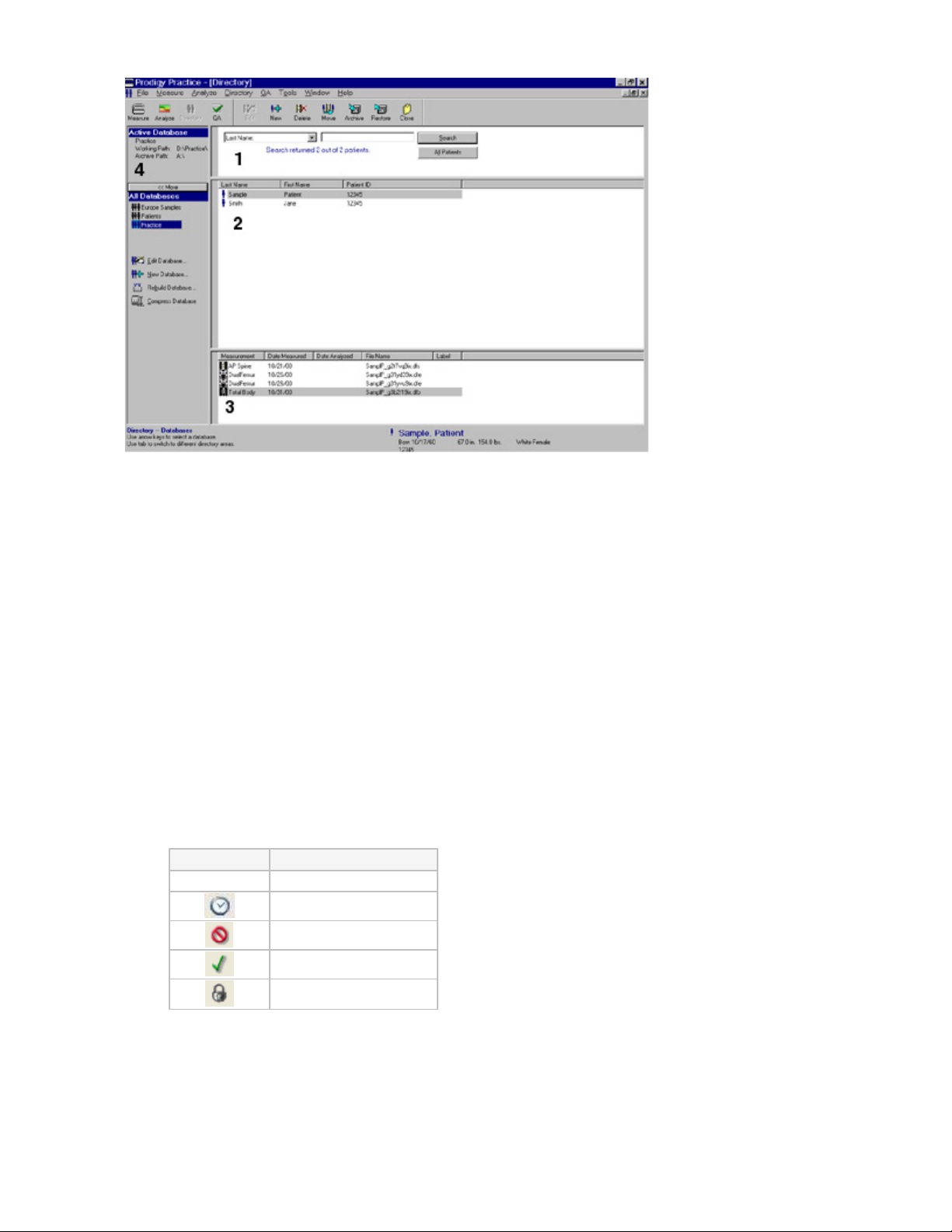
Imaging Tools
Icon Image
Tool
Imaging
(Ctrl+I)
Points
(F4)
Reset
(F3)
Copy
(F5)
Cancel
(Esc)
Results
(Enter)
Report
(Ctrl+Shif
t+P)
Save
(Ctrl+S)
Close
(Esc)
Description
Select to adjust contrast and magnify the image file.
Select to verify that bone and tissue samples are correctly
classified. DO NOT adjust point typing unless the program made
obvious errors.
This option is shown after you select Points. Select Reset to delete
changes you made to point typing.
Use this option to copy ROIs from an existing image file to the
current image file.
This option is shown after you select ROIs or Points. Select Cancel
to delete changes you made to the image file.
This option is shown after you select ROIs or Points. Select
Results to view analysis results for the image file.
Select to create analysis reports for the image file.
Select to save the image file and data to the patient database.
Select to close the image file.
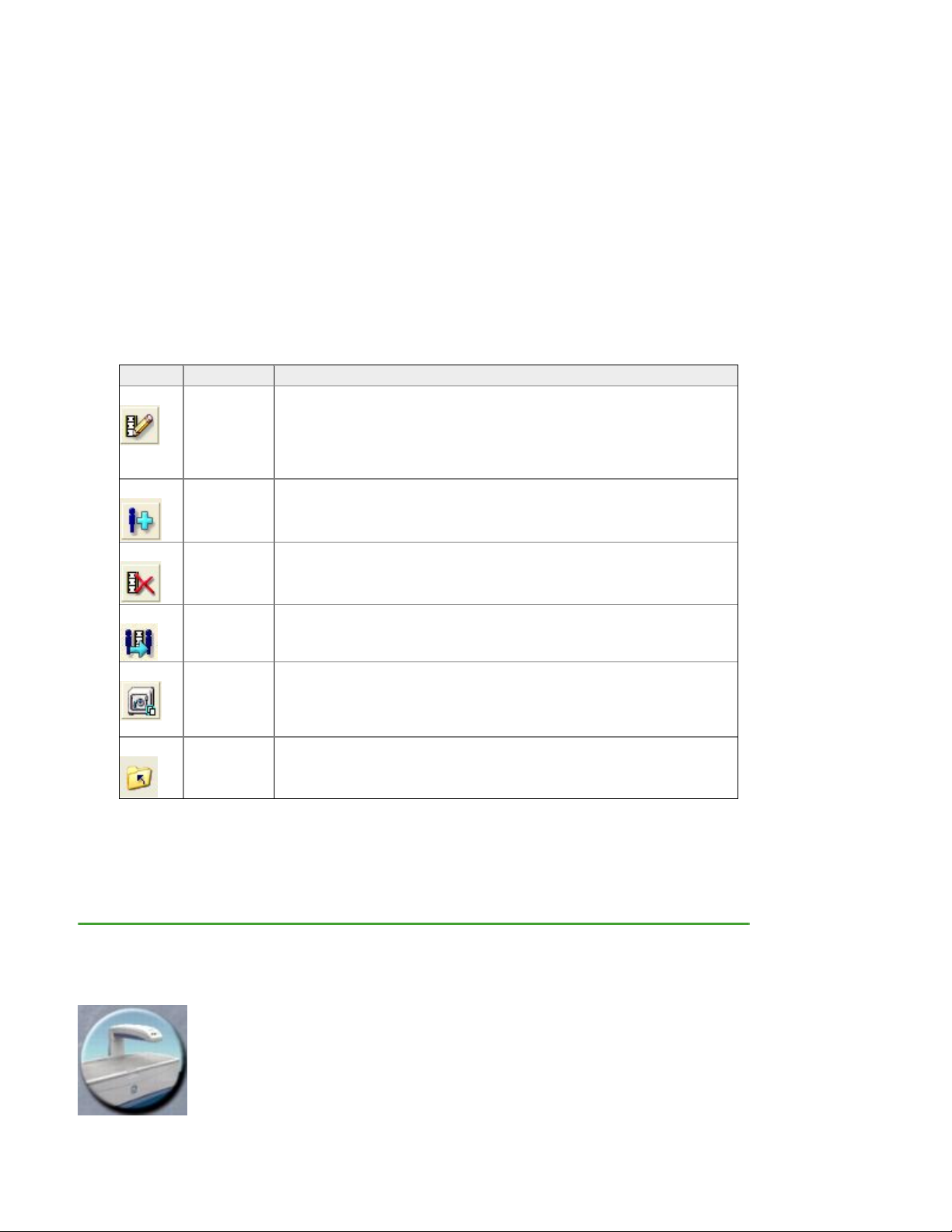
1.4 Directory Screen
The Directory screen is shown when you select Directory from the Main screen or from the
Common toolbar. This screen lists the patient files and images that are stored in the active database.
The Directory Screen is divided into four areas:
1) Search Option
2) Patient List
3) Image List
4) Database Sidebar
Page 18 of 138
Page 19
1.4.1 Search
Use the Search option to quickly locate a patient record and image file in a large database. The Search
option is located near the top of the Directory screen.
1. Select the database field to use in the search (1).
2. Enter the patient information to use in the search (2).
3. Select Search. The patient record and associated image files are shown in the Patient and
Image lists.
The All Patients button clears the search criteria and lists all the patients in the database.
1.4.2 Patient and Image lists
Use the Patient and Image lists to select a patient to measure or an image file to analyze. Double-click
on a highlighted patient record to start a new measurement, or double-click on a highlighted image file to
analyze the image file.
• Patient list: The Patient list shows patient records in the database according to the patient’s
last name, first name, and ID. The patient information for the selected patient is also shown in the
Patient block at the bottom of the Directory, New Measurement, and Analyze screens.
• Image list: The Image list shows the measurement images recorded for a patient according to
measurement type, date measured, date analyzed, file name, and label. The image list may
include exams made up of multiple measurement images. Assign a status or notes to an exam by
right-clicking on the exam in the directory and selecting Change Status or Notes. Choose from a
list of 5 status types:
Icon Status
No Icon Not Reviewed
Pending Review
Rejected
Approved
Closed
Enable Exam Status/notes features and set defaults, actions when sending a report, and status
colors under Tools/User Options/Directory/Directory Status.
1.4.3 Database Sidebar
The Database sidebar shows the database that is currently being used (active database) and the
working path of that directory. The Active Database panel indicates the location of the database and the
drive used for archiving patient studies. Most systems will use a hard drive location for the working path
Page 19 of 138
Page 20
and a removable media drive for the archive drive. This information is always available on the Directory
screen.
All Databases are presented on the database sidebar. Creating more than one database is especially
useful for customers performing research studies. The database currently active is highlighted in the
available databases list. To change databases, highlight the desired database from the list.
The lower portion of the Database sidebar shows all available databases, and database maintenance
options. If you do not see this information, select More >>.
Database Maintenance tools provide the ability to edit, create, rebuild or compress the database. Refer
to Edit Database, Compress Database, or Rebuild Database, New Database, for additional
information.
1.4.4 Directory toolbar
The Directory toolbar displays options that let you work with your patient files.
Icon Tool Description
1.4.5 Help Text
Help Text is located in the lower left corner of every screen in enCORE™ software. The Help Text
provides keystroke functionality, current operation of the system, and instructions for the software user.
Edit
Patient
(Ctrl+E)
New
(Ctrl+N)
Delete
(Del)
Move
(F4)
Archive
(F5)
Close
(Esc)
Select to edit Primary, Secondary, and Additional data for the
highlighted patient record in the Patient list. The edits are not
saved to image files that have already been acquired for the
patient. Use the Edit Image tool to edit information for individual
image files.
Enter a new patient that is not in the patient database.
Select to delete the highlighted patient, exam, or image file. You
can delete the patient, exam, or image record(s), or the record(s)
and related exam or image file(s).
Select to move exam to another patient record.
Select to copy or move exam files from the computer hard
drive to an archive location. You can archive single exams,
single patients, or all patients. You can also archive all exams
for all patients found during a search.
Select to exit the Directory screen.
1.5 New Measurement Screen
The New Measurement screen is used to complete a new measurement
for an existing patient (recorded in the database) or for a new patient. This
screen is shown or when you select Measure from the Common toolbar.
Page 20 of 138
Page 21
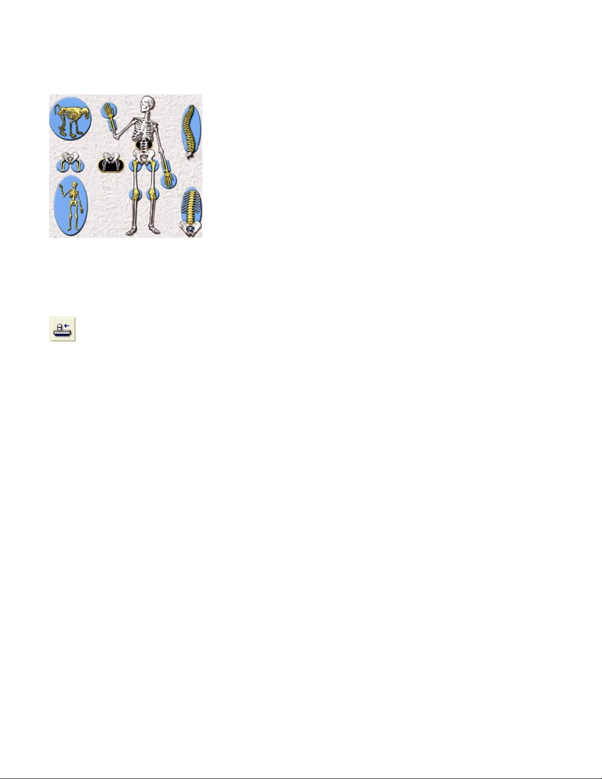
A list of applicable measurement sites is presented on the New Measurement screen. The
user may select the measurement site from the Exam List or highlight the measurement
region on the corresponding Skeletal Image.
1.5.1 "Analyze When Done" option
Select the "Analyze When Done" option if you want to analyze the image file after the measurement:
the Analyze screen is shown immediately after the measurement is complete.
1.5.2 Patient and laser position graphic
When you select Position from the New Measurement toolbar, a graphic is shown
which illustrates the correct patient and laser position for the measurement type. (The
laser is not used for total body measurements.) Review Measurement Procedure for
further information on the appropriate laser starting position.
Page 21 of 138
Page 22
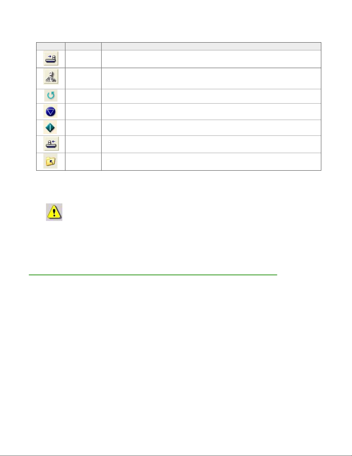
1.5.3 New Measurement Toolbar
Icon Tool Description
Select to move the scanner arm to the Home position.
This option is shown after you select Position. Select Set Up to return to the set
up screen and change the settings for the measurement. In addition, use this
option to select a different measurement type and start a new measurement.
This option is shown after you complete an exam. Select Repeat to reposition the
image and repeat the measurement.
Select to stop the measurement and save, continue (resume), or start a new
measurement.
This option is shown after you select Position. Select Start to start the
measurement.
Select to move the scanner arm to the start position; then, use the controls on the
scanner arm to position the laser light for the measurement.
Select to exit the New Measurement screen.
Home
(F3)
Set Up
(F6)
Repeat
(F4)
Abort
(F5)
Start
(F7)
Position
(F7)
Close
(F8)
1.5.4 Home scanner arm
Select Home Scanner (Ctrl + H) from the Measure menu to move the scanner arm to the home position
from any screen in the program.
Note: If the scan arm has been set to Home at the foot end of the table, and the foam leg block
is used for AP Spine measurement, a warning will appear. Please remove patient positioner.
1.5.5 Park Scanner
Select Park Scanner (Ctrl+K) from the Measure menu to move the scan arm on a mobile system to
the foot of the table for lockdown.
Page 22 of 138
Page 23
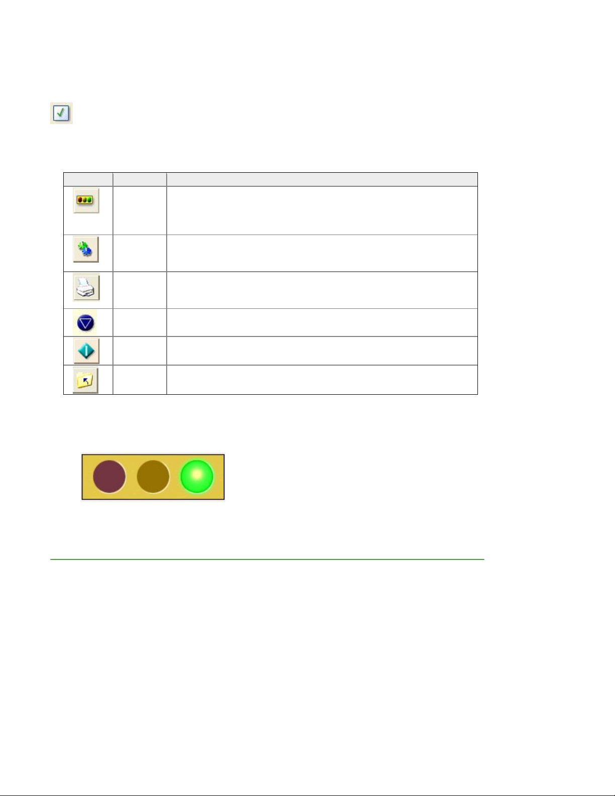
1.6 Quality Assurance screen
The Quality Assurance screen is used to complete a Quality Assurance (QA) procedure. This screen is
shown when you select Quality Assurance from the Main screen or from the Common toolbar.
1.6.1 Quality Assurance Toolbar
Icon Tool Description
Trend
1.6.1 System Status
The Quality Assurance screen indicates the current operating status of the system. The System Status
should indicate 'System is ready to measure patients' before performing patient measurements to ensure
accurate results.
(F2)
Setting
(F3)
Report
(Ctrl+P
Abort
(F5)
Start
(Enter)
Close
(Esc)
QA trending history is automatically shown after a QA procedure
(unless you have changed this behavior in the User Options). If the
trending history is not shown, you can select Trend to view the QA
trending history after you complete the QA procedure.
Select to change information for trending.
s
Select to create a report of the QA results.
)
Select to stop the QA test.
Select to start the QA procedure.
Select to exit the QA screen.
Refer to the topic Quality Assurance for instructions on performing a quality assurance procedure.
Page 23 of 138
Page 24
1.7 Options
elect Options from the Main screen or select the Tools menu to access User Options, Connectivity
S
Options, and the Error Log.
7.1 User Options
1.
User Options le
Select Options
Main screen and ct User Options.
hange the necessary default setting(s).
C
Select OK to save changes. If you do not
User Options Description
t you set and change the program default settings.
(F6) from the
sele
O
R
elect the Tools menu and select User
S
Options.
want to save changes, select Cancel.
Systems
Directory
Analyze
Results Display
Trending
Reference
Data
Image
ScanCheck™
Reports
This tab lists scanner System ID number and Feature code. User Interface Options,
Exam File Options and ISCD settings.If the Automatic return to Directory option
is selected, you will return to the Directory screen instead of the main screen when
you close windows. The Auxiliary Workstation option is shown if you purchased th
e
Multi-User Database kit. Select this option to prevent the workstation from performing
QA procedures or patient measurements. The Number of Open Exams option lets
you choose how many exams can be opened for analysis at the same time.
Use this option to determine how information is sorted in the Patient and Exam/Image
lists and to configure default ethnicity. You can also choose to expand exams by
default.
Enable/Disable analysis features for all scan types.
ation to use and the type of You can also choose the type of Small Animal calibr
forearm calibration to use for BMD results.
The Results Display tab lets you change the appearance of graphs; Standard, WHO
or JSBMR. You can select the information shown in the results tables, select the
composition results to show, and set the Morphometry SD cutoffs.
hs and in Use this option to select the type of information shown on trending grap
trending tables, and configure the software to flag significant change. The
integrated Precision Calculator Tool is also located within this option.
Use this option to select a reference population and show the reference sources on
the screen and the results reports. Use of the reference population comparisons is
fully at the discretion of the clinician. The program does NOT show the
comparative values when shipped from GE Medical Systems LUNAR.
Use this option to set the colors of ROIs, bone edges, and point typed areas of an
image file during analysis, and enable optimal image magnification.
Use this option to select the ScanCheck™ checks that will be included on the
ScanCheck™ tab for AP Spine, Femur, Forearm and Total Body analysis.
Select Patient ID types and Report background color. Under Dexa Report
Configurations select to report on Selected Region Only, Trend Multiple Results,
Invert Image, GE Healthcare Logo, Report Dialog, sBMD Footnote, Comments, Show
Vertebral Height T-Scores, and Show Ethnicity.
Change the Report Center Defaults- where the report will be sent, the types of
reports that will be created, regions to be reported on, and the number of copies f or
each page of the report.
User Information Includes the site name, address, phone numbers, web site and
email information.
Page 24 of 138
Page 25
Morphometry Report Options are configured here.
Composer
QA
Measure
2. Systems Tab
The scanner's System ID is unique. The System ID is needed for support.
The feature code is only compatible with your system ID. It enables the purchased options in your
software. If you wish to try out a feature before buying it, contact your sales person for a trial feature
code.
Icon Function Choices
Configure the file type to output from Composer. Use the Spelling Options to
customize spell checker functions.
Use this option to change the default setting for printing QA reports.
Select Automatic Printing: Daily QA to have the program print a QA report each
time you complete a quality assurance procedure.
Select Automatic Return to Trend Screen to automatically return to the trend
screen once a QA has completed.
Use this option to set the default settings used during a measurement.
Save prompt at end of scan (select this option to show a message after every
measurement that asks you if you want to save the measurement), Allow continue
after SmartScan abort, Use Old Positioner for Lateral Measurements (Densitometry
and Morphometry Only), Show Previous Scan, Allow Scanner Start Button to
initiate a Measurement, LVA reverse (For LVA, scan patient facing foot of table),
Default to seated patient for forearm and hand scans, Pause between Femur
scans, OneScan™ (no Foam Leg Block positioner for AP Spine scans), or Pause
between AP Spine and Femur Scans.
Additional
Feature
Codes
User
Interface
Options
Enter Trial and IRB feature codes. Expiration dates will display below
each feature code.
Automatic return to Directory will return your display back to the
Directory scan after an acquisition is complete.
HIPAA Secure View hides patients in the directory view.
Play Multimedia Sounds option.
Auxiliary Workstation for use with MUDBA setups. The Auxiliary
Workstation option is shown if you purchased the Multi-User
Database kit. Select this option to prevent the workstation from
performing QA procedures or patient measurements. The Number of
Open Exams option lets you choose how many exams can be opened
for analysis at the same time.
HIPAA Secure Filename On: pat_z8gutml1w.dff
HIPAA Secure Filename Off: SmithJf0m485s.dff
Compress Exam Files to conserve space for high resolution images such
as iDXA scans.
Exam
File
Options
Encrypt Exam Files
Page 25 of 138
Page 26
ISCD Official
Position
Acceptance
Select "Yes" to accept the settings recommended by ISCD.
Review current ISCD Positions from the link in the enCORE software.
FRAX
Check box(s) for ‘Enable FRAX’ and/or 'Apply US NOF/ISCD FRAX
recommendations'
Review the NOF/ISCD FRAX Implementation Guide from the link in the
enCORE software for details.
3. Directory Tab
Icon Function Choices
Patient Sort
Options
Exam Sort
Options
Patient List
Columns
Directory
Rules &
Defaults
Sort by First name, Last name or Patient ID
Ascending or Descending
Sort by Measurement, Date Measured, Date Analyzed, File Name,
Archive, Import, or Status
Ascending or Descending
Choose Patient Third column contents:
Patient ID, Facility ID, Department ID or Exam ID
When duplicate patients occur follow Duplicate Patient Match Rule.
Select Default Gender, Default Ethnicity, Duplicate Patient Match
Rule:
Use Patient Last Name & Birthdate or Use Patient ID.
Checkbox Option to Expand Exams view in the directory by Default.
Enable Exam Status/notes features. Also, set defaults, actions when
sending a report, and status colors.
Directory
Status
Page 26 of 138
Page 27
4. Analyze Tab
Icon Function Choices to Appear in the Results
Femur Analysis
Options
Total Body
Analysis
Options
Forearm
AHA: Hip Axis Length, Upper Neck region, Lower Neck region,
Calculate Hip Strength results and Hip Geometry results
Calculate Left and Right results
Calculate Total Body Less Head (TBLH) result (used for Pediatric)
Forearm Calibration: Lunar, SPA or Comac
Analysis
Options
Orthopedic
Analysis Options
Small
Standard Gruen zones or Extended Gruen zones
Calibration: Chemical/Ash or Lunar
Animal/Research
Options
Morphometry
Options
Finish Button
Options
Estimated Total
Body
Create ROIs on Request (Recommended)
Automatically create Reference ROIs when needed
Automatically create ROIs for T8-L4 when opening exam
Finish Button On/Off
Operation to perform: Send Report(s) to destinations, Save Exam and
Close Exam
Estimate % Body Fat from Spine/Femur scan On or Off
5. Results Display Tab
Icon Function Choices
Reference Graph
Options
Densitometry Table
Options
Young Adult (YA) Bars: Standard SD, WHO or JSBMR
Show Y2-axis values
Age-Matched (AM) Bars appearance and SD applied
Young Adult (YA) in % or T-Score, Age-Matched (AM) in % or
T-Score.
Show BMC, Show Area, Show Diagnostic Category Icons
and Show All DualFemur Regions
Composition Options
Morphometry
Reference Options
BMI Options
Z-Score or Centile Results
Metric or English measurement system
Reference in Z-Score or Percent Height Reduction
Configuration for assigning deformity Mild, Moderate and Severe
BMI cut-off points assigned per WHO or Custom
BMI On or Off
Page 27 of 138
Page 28
6. Trending Tab
Icon Function Choices
Trend Graph Options
Trend Table Options
Precision Calculator
Select Line Pattern, Densitometry Trend Graph, Morphometry
Trend Graph, or Composition Trend Graph settings.
Flag Significant Change On or Off. Configure how trending is
to be displayed.
A complete Precision Tool to determine Least Significant
Change (LSC) for scan types: AP Spine, Femur, DualFemur,
Choice of Measures
to Trend On
Total Body, Forearm, Hand and Lateral Spine
For Densitometry Pediatric, Densitometry Adult,
Morphometry, Composition Y1 axis, Composition Y2 axis,
Estimated Composition Trend, and Pediatric Growth Trend.
7. Reference Data Tab
Function Choices
Choice of Reference
Population
Asia, Australia (Combined Geelong/Lunar), Australia (Geelong),
Australia (Lunar), Brazil, China, Egypt, Finland, France, Germany,
Indonesia, Italy, Japan, Korea, Mexico, Middle East, Philippine,
Spain, Tunisia, Turkey, UK, USA (Combined BMDCS/Lunar), USA
(Combined NHANES/BMDCS/Lunar), USA (Combined
NHANES/Lunar), USA (Lunar)
Scan Site
AP Spine, Femur, LVA, Total Body, Forearm or Lateral Spine
Choice of Default Region
for Each Scan Type
Choose the region that will be the default region for analysis for each
scan type
8. Image Tab
Icon Function Choices
Image Options
On or Off for: Interpolation, Invert Image, Show bone edges, Show
Artifacts, Size Image to Fit screen on Open.
Display On or Off: Two Total Body images, Dual Femur Images
top/bottom, Composition Image for Total Body.
Image Colors
Change image colors for ROIs, Zoom Region/Masks, Bone Edges,
Point Typing, Markers and Artifacts
Image Export
Options
Morphometry
Wizard Options
JPG Quality set
LVA Wizard Zoom Margin set in millimeters
9. ScanCheck™ Tab
Select the ScanCheck™ items that you would like to show in the analysis screen.
ScanCheck™ On or Off
Page 28 of 138
Page 29
Set ScanCheck™ view to appear first when analyzing
Include ScanCheck™ indications on report.(bottom of screen)
Show AP Spine
Detect the following problems
Alert
Measure
Technique
Correct scan mode used?
Analysis
Technique
AP Spine alignment reasonably straight?
Optimal contrast and brightness set?
ROIs properly defined?
L1-L4 labeled correctly?
Tissue region properly defined?
Bone edges properly defined?
Results consistent with previous scan?
Analysis region free of unusual high density bone?
Anatomy
Issues
Free of unusual T-Score variation?
Free of unusual curvature?
AP Spine - Comments:
Show Femur Alert Detect the following problems
Measure
Technique
Correct scan mode used?
Sufficient pelvis and shaft separation?
Femur shaft reasonably straight?
Proper femur rotation?
Analysis
Technique
Optimal contrast and brightness set?
ROIs properly defined?
Tissue region properly defined?
Bone edges properly defined?
Results consistent with previous scan?
Anatomy Issues
Analysis region free of unusual high density bone?
Page 29 of 138
Page 30
Femur - Comments:
Show Total Body Alert Detect the following problems
Show Forearm Alert Detect the following problems
10. Report Tab
Icon
Measure
Technique
Analysis
Correct scan mode used?
Patient within scan field?
Optimal contrast and brightness set?
Technique
ROIs properly defined?
Patient Height Entered Correctly?
Patient Weight Entered Correctly?
Anatomy Issues
Analysis region free of unusual high density bone?
Total Body - Comments:
Measure
Technique
Analysis
Forearm alignment reasonably straight?
Optimal contrast and brightness set?
Technique
ROIs properly defined?
Anatomy Issues
Tissue region properly defined?
Bone edges properly defined?
Analysis region free of unusual high density bone?
Forearm - Comments:
Function Choices
Report Patient ID
Types
Report Colors
Patient Name, Patient ID, Facility ID, Dept ID, Exam ID,
Attendant, Referring Physician, Reading Physician or blank.
Change the background color of DXA Reports
DXA Report
Configuration
Selected Region Only, Trend Multiple Results Only, Invert Image,
Show GE Healthcare Logo, Show Report Dialog, sBMD Footnote
on, Show Comments, Show Vertebral Height T-Score, Show
Ethnicity
Report Center
Defaults
Opens the Report Center Window for configuration. See
Report Center Chapter for more information.
Report Regions
Select the regions desired for each scan type. "Selected
Region" will report the region currently highlighted on screen
Page 30 of 138
Page 31

Report Regions for
Trending
User Information
Select the trend regions desired for each scan type.
User Information will be used as a header for all DXA reports
Morphometry
Report Options
Morphometry Trend Regions: Deformities Only or All Regions
Morphometry Trend Results: Average Height, Posterior Height,
Middle Height, Anterior Height,
P/A Ratio, M/P Ratio and A/P Ratio
11. Composer Tab
Icon Function Choices
Image Storage
JPG, PNG, or WMF
Format
Chart Storage Format
JPG, PNG, or WMF
Object Storage
JPG, PNG, or WMF
Format
Quality and
Resolution for JPG &
PNG
Spelling Options
PDF Export Security
Settings
Automatic or manual configuration of Quality
Automatic or manual configuration of Resolution
General options, Spelling Suggestions, Dictionary or
Customized Dictionary, Advanced Settings and Performance
& Accuracy settings
Add password protection to PDF documents exported
Set permissions for printing and editing.
Display ICD9 codes
with Fractures,
ICD9 Codes On or Off
Indications and
Treatments
12. QA Tab
Icon Function Choices
Default QA Copies
Automatic Daily QA
Print
Automatic return to
trend screen
Graphical Interface
Enter number of copies
On or Off
On or Off
On or Off
Enable QA stability
analysis
Compress Patient
Database after QA
Allow QA Block scans
outside of Daily QA
On or Off
On or Off
On or Off
Page 31 of 138
Page 32

QA Means
Reset Means Activation
QA AutoMentor
Enable AutoMentor to automatically export QA report to email
or Fax if QA fails
13. Measure Tab
Icon Function Choices
Save Prompt at the end of a scan
Allow a continue option after SmartScan abort
Show Previous Scan
Allow Scanner Start Button to initiate a
Measurement
Use Old Positioner for Lateral Measurements
(Densitometry and Morphometry only)
LVA Reverse scan arm direction. Patient head
at foot of the table.
Default to seated patient for forearm and hand
scans
Pause between Femur scans
OneScan (Foam Leg Block positioner not used
for AP Spine scans)
Pause between AP Spine and Femur scans
Adjust the speed of movement of the scan
arm: Transverse Joystick Speed &
Longitudinal Joystick Speed
Download scanner firmware (service tool)
On or Off
On or Off
On or Off
On or Off
On or Off
On or Off
On or Off
On or Off
On or Off
On or Off
Faster or Slower
Initiate download
1.7.2 Connectivity Options
Connectivity options let you change report delivery, fax, email, DICOM, and HL7 default settings.
1. View Connectivity Options:
Select
(F6) from the Main
screen and select Connectivity
Options.
2. Select one of the Connectivity Options tabs that follow:
Connectivity
Description
Options
Report Delivery
Use this option to select the recipient of your e-mailed and faxed results reports.
Referring physician-The program sends reports to the physician listed in the
patient's Primary information.
OR
Page 32 of 138
Select the Tools menu and select
Connectivity Options.
Page 33

Fax
Email
DICOM
HL7
Support
1.7.3 Error Log
In the event you encounter difficulties which prevent normal operation of the program, view the Error Log
for a list of errors that may be causing the problem. Service will need the digital file of errors.
1. To view the Error log:
Select Options
the Main screen and select Error
log...
2. To export the error logs go to Tools / Send Configuration and check the options to export.
The Error log consists of two sections:
• Sessions–This section lists the dates and times that the program was being us ed and the
number of errors that occurred during each session.
• Errors–This section gives a description of each error that occurred during the selected session.
Reading physician-The program sends all reports to the physician listed in this
field.
Use this option to change the default settings for the fax feature.
The Receive Incoming Faxes feature lets you receive faxes if you have a fax
modem attached to your system.
The Invert Image feature lets you invert the gray scale for images on your
faxes.
An analog phone line is required.
The Fax option is only available if you purchased the TeleDensitometry kit.
Use this option to change the default settings for the email feature. In Outlook
Express or Outlook, setup a "Personal Address Book" to interface with
enCORE.
The Add case information to Subject feature automatically includes the
patient's name, the scan type, and the name of the file you are emailing in the
Subject line of the email message. Make sure a check appears in the check
box if you want to use this feature.
The Invert Image feature allows you to invert the gray scale for images in your
emails.
The Image quality drop-down list allows you to choose the quality level for
images included in your emails. Quality affects the size of the image.
The Email option is only available if you purchased the TeleDensitometry kit.
Use this option to change the default settings for the DICOM feature. If you
change the store folder location, you will also have to change the Report Folder
Location setting in the LUNAR DICOM program.
The DICOM Worklist feature displays a list of patients who are scheduled for
DXA measurements. The list is supplied by the hospital information system.
Make sure a check appears in the Directory in Worklist Mode check box if you
want to use this feature. The DICOM option is only available if you purchased
the DICOM kit.
Use this option to change the default settings for the HL7 feature.
The Worklist Mode feature displays a list of patients who are scheduled for
DXA measurements. The list is supplied by the hospital information system.
The Reporting option can send Text and Images in HL7 format. DO NOT
change any of the HL7 default settings without authorization from your network
administrator. The HL7 option is only available if you purchased the HL7 kit.
This option lists the fax and email information for your service provider. The
program uses this information to email or fax QA reports to your service
provider if the QA procedure fails.
Select the Tools menu and select
(F6) from
OR
Error Log.
Page 33 of 138
Page 34

Troubleshoot button takes you to a help topic about the selected error. Find Errors takes you to similar
errors in the list.
If you cannot correct the error condition, go to Tools / Send Configuration and check the Error log and
Configuration files options. Email the files into support. Or you can print the Error log by selecting Print
Errors. Call your GE representative and provide them with the error description as shown in the Errors
section.
2.0 Quality Assurance
2.0.1 Daily Quality Assurance Procedure
Complete a Quality Assurance (QA) test each morning before you measure a patient. If the room
temperature changes more the 5°C during the day, then perform another Daily QA. This procedure
calibrates and verifies functionality, as well as, the accuracy and precision of the densitometer. The QA
procedure should be performed a minimum of once a week if the scanner is not being used. Save all QA
printouts.
Use the black calibration block to complete a QA test (the calibration block consists of tissue-equivalent
material with three bone-simulating chambers of known bone mineral content). Leave the pad on the
scanner table during the QA procedure.
1.
toolbar.
2.
3. Put the calibration block on the pad so that the laser light (1) rests in the center of the cross-hair label
on the calibration block.
4. Select OK. Follow the screen prompts to complete the QA procedure.
5. If the QA test did not pass, reposition the calibration block and repeat the procedure. If the procedure
fails a second time, call Lunar Support for assistance.
6. To print the QA results, select Report if the auto print option is not set. Save the QA printout.
Select Quality Assurance (F5) from the Main screen or select QA from the Common
Select Start. A message instructs the technician to position the calibration block.
Laser
Brass on bottom
Page 34 of 138
Page 35

2.0.2 Quality Assurance Options
Go to Tools / User Options / QA tab.
Click here or go to the Options chapter.
2.0.3 Graphical Interface
Startup
Test:
Mechanical
Test:
X-ray /
Detector:
Calibration: BMD values of High, Medium and Low block
Phantom: BMD, BMC, Area,
Database Validation
Scanner Self-test
QA Block Search
Peaking
Beam Stop
Transverse Distance
Longitudinal Distance
Spectrum Spillover
Reference Counts
Detector Status
chambers
Tissue values of Lean, Normal and Fat block values
Trend analysis
Edge detection
Click on the Trend tool to exit out of the QA process screen.
2.0.4 QA Trend Reporting Options
Click on Settings. The settings screen provides many options for QA trend reporting components.
In the upper right panel are options for the QA Report Type.
• QA Phantom Report
• Ancillary page
• Legacy QA Report
Page 35 of 138
Page 36

QA Phantom Report QA Ancillary page
Legacy QA Report
Page 36 of 138
Page 37

3.0 Measurement
3.1 Measurement Overview and Warnings
3.2 Measurement Procedures
3.3 Pediatric Measurement
3.4 OneScan Feature
3.5 OneVision Feature
3.6 Orthopedic Hip Measurement
3.7 Quick View
3.8 Phantom Procedure
3.1 Measurement Overview & Warnings
Patient considerations:
Obey the patient considerations that follow before you start a patient measurement:
• Clothing restrictions: Make sure the patient removes items that can attenuate the x-ray beam, such as
clothing with zippers, snaps, buckles, and buttons. Ask patients to wear a jogging suit to the exam or give them
an examination gown when they arrive.
• Radionuclide and radiopaque agents: Make sure the patient has not ingested or been injected with
radionuclides or radiopaque agents in the past 3–5 days. If the patient has taken tests that use such agents,
postpone the measurement until all traces of the element have left the patient’s body. A 72-hour waiting period
is usually long enough for most agents to leave the patient’s body. However, consult your radiation safety
officer (RSO).
• Pregnancy restrictions: If it is necessary to measure a pregnant patient, the fetus could be exposed to small
amounts of radiation. Postpone the measurement until the end of pregnancy if clinical management is not
affected. The decision to subject a fetus to radiation exposure must be made by the referring physician, noti ng
that 1) bone quality for most patients does not significantly change during pregnancy and 2) in the advanced
stages of pregnancy, the fetus’ mineralized bone can interfere with measuremen ts of the mother’s spine and
femur.
Measurement Warnings
WARNING: Each GE LUNAR scanner is equipped with a Class II Laser that is less than 1
milliwatt in strength. DO NOT STARE INTO THE BEAM.
WARNING: Remove Foam Leg block prior to positioning scan arm over the patient
and immediately after completing an AP Spine scan.
WARNING: Insure the patient's head, arms, knees or any body part are not in direct
path of a moving scan arm.
Page 37 of 138
Page 38

3.2 Measurement Procedures
This section describes the basic steps necessary to complete a patient measurement. These steps mu st be
completed in the order given. Review the steps before you start a patient measurement.
Note the following, whenever you see the following symbol:
WARNING: Each GE LUNAR scanner is equipped with a Class II Laser that is
less than 1 milliwatt in strength. DO NOT STARE INTO THE BEAM.
WARNING: Remove Foam Leg block prior to positioning scan arm over
the patient and immediately after completing an AP Spine scan.
WARNING: Verify the patient's head, arms, knees or any body part are not
in direct path of a moving scan arm.
3.2.1 Step 1: Record or select patient
To complete a patient measurement, you must record information for a new patient or select a patient
record from the database.
Record new patient information
1. Select
2. Record the nece ssary information in the three tabs that are shown on the Patient Information dialog
box:
• Primary tab–You must record the patient’s name, birth date, height, and weight to complete a
patient measurement. Change the default gender or ethnicity in the Tools/User Options/
Directory/Directory Rules and Defaults.
• Secondary tab–The Secondary tab lets you record comments and administrative information that
is not required to complete a patient measurement. If the ISCD guidelines are turned on under
Tools/User Options/Systems, it is important to enter a menopause age for postmenopausal
women as the WHO criteria will only be applied to postmenopausal women and men age 50 and
older.
• Additional tab–The Additional tab lets you record fracture, indication, and treatment information
for the patient. In addition, you can also enter the patient’s insurance information. This information
is not required to complete a measurement.
from the Main screen or from the Directory toolbar.
Page 38 of 138
Page 39

3. Select OK when you have finished recording the patient information. The New Measurement screen
is shown if you started from the Main screen; if you started from the Directory screen, highlight the
patient's name and select Measure from the toolbar to go to the New Measurement screen.
Select existing patient record
Select a patient for a new measurement from either the Main screen or the Directory screen.
Use the Search option to find the patient, if necessary.
Main screen
a. Select Measure. The Patient Information dialog box is shown.
b. Select Find. The Patient and Image lists are shown.
c. Double-click on the patient in the Patient list. The Patient Information dialog box is shown.
d. Make sure the patient information is correct, then select OK. The New Measurement screen is
shown.
Directory screen
Double-click on the patient in the Patient list, or highlight the patient and select Measure from the
Common toolbar. The New Measurement screen is shown.
3.2.2 Step 2: Select measurement site
The New Measurement screen shows a skeletal image which give s the sites you can select to
measure. Use the mouse to click on the site you want to measure. The site you select is
highlighted in the Exam list.
Information about the measurement modes is located in the Safety Information and Technical
Specifications manual you received with your system.
Now follow the measurement procedure for the site you selected.
3.2.3 AP Spine measurement
The positioning requirements for an AP Spine measurement depend on whether you have chosen to use
the foam leg block positioner in the User Options Measure tab.
The foam block must not be used if OneScan™ is checked for a specific measurement, but it must be
used if OneScan™ is not checked for the measurement. For OneScan™ measurements, the T-Score
calculation assumes the foam block is not used.
1. Foam Leg Block
• If you are using the foam leg block positioner:
Help the patient onto the scanner table and position the patient as follows in the center of the scan
table. Use the centerline on the table as a reference to align the patient.The patient's arms should be
on the scanner table, alongside the patient's body.
•
after the AP Spine scan.
Warning: Remove the foam leg block prior to positioning the scan arm and immediately
Page 39 of 138
Page 40

• If you are using the foam leg block:
2. OneScan™
• OneScan™ Does not use the foam leg block positioner:
• OneScan™ Does not use the foam leg block positioner:
Select Position from the New Measurement toolbar. The scanner arm moves to the
approximate start
position. A graphic is shown that gives the correct patient position and
measurement start position.
Use the support block to elevate the patient's legs. Make sure the patient's thighs form a 60°to 90°
angle with the table top. This step helps separate vertebrae and flatten the lower back.
Help the patient onto the scanner table and position the patient as follows in the center of the scan
table. Use the centerline on the table as a reference to align the patient. The patient's arms should be
crossed over the chest, away from the side of each hip.
Select Position from the New Measurementtoolbar. The scanner arm moves to the
approximate start
position. A graphic is shown that gives the correct patient position and
measurement start position.
Use the centerline on the scanner table as a reference to make sure the foot brace is centered. Align
the centerline with the guide on the base of the foot brace. Internally rotate the patient's legs, and
secure the patient's feet to the foot brace (GE-Lunar suggests not removing the shoes).
Page 40 of 138
Page 41

3. Laser Position
Use the graphic shown to adjust the position of the laser light. Position the laser light
approximately 5 cm below the patient's navel and in the same longitudinal plane as the patient's
midline.
4.
Select Start from the New Measurement toolbar to start the measurement. Monitor the image to make
sure it is correct.
5. Make sure the spine is in the center of the
image, all of L4 (1) is shown, the top of L5 (2) is
shown in the first 1-2 sweeps for Prodigy, 5-15
scan lines for DPX. (3) Approximately 1/2 of
T12 is shown.
If the image is not correct, select Abort,
reposition the laser light, and restart the
measurement.
6.
If you want to complete another
measurement for the patient, select Set Up from
the New Measurement toolbar. Refer to the
topic New Measurement screen for additional
screen functions.
7.
If you have completed measurements for the patient, select Home to move the scanner arm to
the Home position.
8.
Select Close to exit the New Measurement screen. Refer to the topic New Measurement screen for
additional screen functions.
3.2.4 Femur/DualFemur measurement
1. Help the patient onto the scanner table and position the patient as follows:
The patient's body is in the center of the scanner table - use the centerline on the table as a reference
to align the patient. The patient's arms are crossed over the chest, away from the side of each hip.
Page 41 of 138
Page 42

2.
Select Position from the New Measurement toolbar. The scanner arm moves to the approximate
position.
start
3. A graphic is shown that gives the correct patient position and measurement start position for the site you are
measuring. Use the centerline on the scanner table as a reference to make sure the foot brace is centered.
Align the centerline with the guide on the base of the foot brace. Internally rotate the patient's legs, and
secure the patient's feet to the foot brace (GE-Lunar suggests not removing the shoes).
4. Select the appropriate scan mode based on the thickness of the femur area. Note that the scan mode for
the femur may be different than the scan mode used for the AP Sine, based on the patient's weight
distribution. Use the graphic shown to adjust the position of the laser light. Position the laser light
approximately 7-8 cm below the greater trochanter where the transverse (Pubic Symphysis) and midline of
the femur intersect. If you are performing a DualFemur™ measurement, position the laser light for the
left femur first.
5.
Select Start from the New Measurement toolbar.
Monitor the image to make sure it is correct. The Femur
image shows the greater trochanter (1),
femoral neck (2), and ischium (3).
A minimum of three centimeters of tissue should be shown
above the greater trochanter and below the ischium.
Select Abort and reposition the laser light if the image is not correct.
DualFemur:
DualFemur lets you measure the patient's left and right femur in an automatic sequence. After the
program has measured the left femur, the scan arm moves to the approximate start position for the right
femur. Check the start position and, if necessary, adjust the measurement start position for the right
femur.
Note: DPX-Duo and DPX-Bravo have a narrow scan region. Therefore, repositioning the patient for the
contra-lateral femur may be necessary.
Page 42 of 138
Page 43

Select Close to exit the New Measurement screen. Refer to the topic New Measurement screen
for additional screen functions.
3.2.5 Forearm measurement
1. Put the forearm positioner on top of the pad. The L UNAR logo should be located near the patient's
fingers. The forearm positioner keeps the patient's forearm from moving during a measurement.
2. Seat the patient in a chair next to the scan table.
Note: Use a chair without arms or wheels. Use the same chair for all forearm m easurements to get
optimal precision.
Note: Lunar iDXA and Prodigy scanners have an option to scan the patient in a non-seated position with
the scan positioner under the forearm (Tools /User Options/Measure tab). Continue to use the same
method of positioning. If previous scans were done in a seated position, continue to use the same
scanning method to trend data.
Page 43 of 138
Page 44

3. The arm is place d on the positioning board with the palm down with the hand near the Lunar label (1). Tell
the patient to make a loose fist.
The red line (2) shows the center of the measurement area. Center the patient's forearm along this line. The
black lines (3) show the boundary of the measurement area. Position the patient's forearm so that both the
radius and the ulna are between these lines. The blue line (4) shows the starting point of the measurement.
Position the patient's forearm so the distal end of the ulna is at this line. Position the laser light at this line(4)
when you start a measurement.
4. Attach the velcro straps over the fist and over the arm immediately below the elbow. The straps must be
outside the measurement region.
5.
Select Position from the New Measurement toolbar. The scanner arm moves to the approximate
start position. For forearm measurements, be careful that the scanner arm does not bump the patient's head.
6. Use the graphic shown on the New Measurement screen to adjust the position of the laser light. The Laser
Light is positioned in the center of the wrist, adjacent to the ulna styloid. If necessary, move the positioner
and the patient's arm so that the laser light shines in the center of the patient's arm and is aligned with the
blue line on the forearm positioner. Make sure the patient's elbow makes a 90-degree angle, and make sure
the forearm positioner is straight on the table top. All of the ulna styloid should be visible. The forearm bones
should be centered and straight.
Page 44 of 138
Page 45

7. Select Start from the New Measurement toolbar to start the measurement. Monitor the image to
make sure it is correct.
Make sure the forearm is in the center of the image and the distal end of the ulna (1) is shown near the
top of the image. If the image is not correct, select Abort, reposition the laser light, and restart the
measurement.
8.
Select Close to exit the New Measurement screen. Refer to the topic New
Measurement screen for additional screen functions.
3.2.6 Lateral Spine/LVA measurement Option
1. Put the lateral positioner o n the table.
Positioner A should unfold and set over the back rail of the table. Positioner B (1) should be
placed on top of the spine strap (2) and against the back rail of the table.
2. The lateral positioner and the instructions below are intended to position the lumbar spine straight and
parallel to the scanner table. Refer to the figure below to complete the steps that follow.
• Set a pillo w on the table for the patient's head.
• Position the patient's knees toward the chest until the lower back and both shoulders are flat against
the lateral positioner.
• Make sure th e patient's spine is parallel to the scanner table.
Page 45 of 138
Page 46

3. Positioner A:
Refer to the figure below to complete the steps that follow for Positioner A:
• Place a pillow under the pa t ient's head.
• Set a foam wedge below t he bottom knee and between the knees for comfort.
• Make sure th e patient's back and hips are flat against the positioner.
• Patient's arms should be 90-degrees from the chest.
4. Positioner B:
Refer to the figure below to complete the steps that follow old Positioner B:
• Pull the compressor strap over the patient's torso and secure it to the back of the positioner. Make
sure the strap does not hang over the back edge of the scanner.
• Set a foam wedge betwee n the patient' s thigh s and the bottom of the positioner. Set a second wedge
between the patient's knees, and set a third wedge below the bottom knee. Make sure the patient's
back is flat against the positioner and adjust the strap so the patient does not roll forward during the
measurement.
• Adjust the foam wedge between the back of the patient's thighs and the positioner to hold the knees
in place during the measurement.
5.
Select Position from the New Measurement toolbar. The scanner arm moves to the approximate
position.
start
6. Adjust scan length or width as needed. LVA Morphometry scan length can be increased to 55.4 cm. LVA
Spine Geometry scan length should be increased to 69.5 cm. For patients that a unable to re st on their left
side for LVA scanning, select the Reverse box to allow the patient to rest on their right side and reverse the
scan arm direction. Use the graphic shown on the New Measurement screen to adjust the position of the
laser light. Position the laser light at the top of the patient's iliac crest.
Page 46 of 138
Page 47

Lateral Spine measurement
End in L1
All posterior
elements visible
2.5+ cm tissue
Start in Sacrum so
that all of L5 is visible
Laser Light
LVA Morphometry measurement
2.5+ cm
tissue
Laser Light
End near T4
All posterior
elements visible
Start at Sacrum so
all of L5 is visible
Note: An LVA measurement only produces BMD results when SmartScan is turned off.
When SmartScan is on, the scan time is reduced.
LVA Spine Geometry measurement
End near C1
All posterior
elements visible
Start in Sacrum so
all of L5 is visible
2.5+ cm tissue
Laser Light
7.
Select Start from the New Measurement toolbar to start the measurement. Monitor the image to make
sure it is correct.
8. Make sure the image is correct.
• The image starts in the Sacrum so that all of L5 is visible..
• At least 2.5 cm of soft tissue is shown on the anterior side of the verteb rae.
• The image ends in L1 for a Lateral Spine measurement, near T4 for an LVA Morphometry
measurement, or near C1 for a LVA Spine Geometry Measurement.
Page 47 of 138
Page 48

• All of the posterior elements appear in the image.
• The edge of the positione r may appear in the image. This is not a problem.
If the image is not correct, select Abort, reposition the laser light, and restart the measurement.
9.
If you have completed measurements for the patient, select Home to move the scanner arm to the
Home position.
10.
Select Close to exit the New Measurement screen. Refer to the topic New Measurement screen for
additional screen functions.
3.2.7 APVA Measurement Option
1. Follow the same scan procedure that is typically for AP Spine measurements.
2.
Select Position from the New Measurement toolbar. The scanner arm moves to the approximate
start position. APVA Morphometry scan length can be increased to 55.4 cm. APVA Spine Geometry scan
length should be increased to 69.5 cm.
3. Use the graphic shown on the New Measurement screen to adjust the position of the laser light. Position
the laser light approximately 5 cm below the patient's navel. End the scan in T4 for APVA Morphometry
Measurement or near mandible for APVA Spine Geometry Measurement.
APVA Morphometry Measurement
Center and Square
Patient
End at T4
Laser Light
~5
cm below
navel
Start in L5
Page 48 of 138
Page 49

APVA Spine Geometry Measurement
Center and Square
Patient
End at
Mandible
Laser Light ~5
cm below navel
Laser Light ~5
cm below navel
Start in L5
4. Select Start from the New Measurement toolbar to start the measurement. Monitor the image to
make sure it is correct.
5. Make sure the image is correct. If the image is not correct, select Abort, reposition the laser
light, and restart the measurement.
6.
If you have completed measurements for the patient, select Home to move the scanner arm to
the Home position or select next.
7.
Select Close to exit the New Measurement screen. Refer to the topic New Measurementscreen
for additional screen functions.
3.2.8 Dual VA Measurement Option
Dual VA measurement includes both APVA and LVA measurements in one exam
.
3.2.9 Total Body Measurement Option
1. Make sure all attenuating materials (belts, metal buttons, etc.) are removed from the measurement region. For Total
Body scans, all materials that may cause significant attenuation must be removed.
2. Help the patient onto the scanner table and position the patient as follows:
A the patient’s body is in the center of the scanner table—use the centerline on the table as a
reference to align the patient. Note: If a patient is wider than the scan area, the patient can be
positioned for a half body scan. In addition to all of the left or right side of the body, the entire head and
spine should be included in the scan window.
Page 49 of 138
Page 50

B the patient’s hands are turned on sides with thumbs up, palms facing legs and arms are alongsi de the
patient’s body. If possible, hands should not touch legs. Verify that the patients arms are within the
scan area lines on the table pad.
C velcro strap
A B C
3. Select Position from the New Measurement tool bar. The scanner arm moves to the approximate start
position.
4. A graphic is shown that gives the correct patient position and measurement start position for the site you are
measuring. Remove the patient’s shoes. Make sure the patient’s head is approximately 3 cm below the
horizontal line on the table pad. Use the velcro straps to secure the patient’s knees and feet to prevent
movement during the measurement.
Note: You are not required to adjust the scan arm position for Total Body measurements.
5.
Select Start from the New Measurement toolbar to start the measurement.
6. Monitor the image to make sure it is correct. A correct
Total Body image shows the patient's entire body. Make
sure the head (1), feet (2), and patient’s arms (3) are
shown in the image.
If the image is not correct, select Abort and
reposition the patient.
7.
If you have completed measurements for the patient, select Home to move the scanner arm to
the Home position.
8.
Select Close to exit the New Measurement screen. Refer to the topic New Measurement
screen for additional screen functions.
Page 50 of 138
Page 51

3.2.10 Hand Measurement Option
1. Set the patient in a chair next to the scan table. Have the patient place the hand flat on the table, 2 cm from
the line on the table pad, with the thumb and fingers together.
Note: Use a chair without arms or wheels. Use the same chair for all hand measurements to get optimal
precision.
Note: Lunar iDXA scanners also have an option to scan the patient in a non-seated position with the
scan positioner under the hand (Tools /User Options/Measure tab). Continue to use the same method of
positioning. If previous scans were done in a seated position, continue to use the same scanning method
to trend data.
Non-Seated (iDXA
only)
Seated
Laser Light: In
center of wrist,
adjacent to ulna
styloid
Fingers and thumb flat
and together
2.
Select Position from the New Measurement toolbar. The scanner arm moves to the approximate
position. For hand measurements, be careful that the scanner arm does not bump the patient's head.
start
Position hand 2 cm from the line
on the table pad, fingers and
thumb flat and together
Page 51 of 138
Page 52

3. Use the graphic shown on the New Measurement screen to adjust the position of the laser light. If
necessary, move the positioner and the patient's arm so that the laser light shines in the center of the wrist,
adjacent to the ulna styloid.
.
All of the Ulna Styloid is visible
Let scan
proceed past all
fingertips
Laser Light: In center of wrist, adjacent
to ulna styloid
4.
Select Start from the New Measurement toolbar to start the measurement.
5. Monitor the image to make sure it is correct. Make sure the scan proceeds past all fingertips, and make sure
that all of the ulna styloid is visible. If the image is not correct, select Abort and reposition the patient.
6.
If you have completed measurements for the subject, select Home to move the scanner arm to the
Home position.
7.
Select Close to exit the New Measurement screen. Refer to the topic New Measurement screen for
additional screen functions.
3.2.10 Small Animal Body Measurement Option
CAUTION: This software is for investigational use on laboratory animals or for other tests that do not involve
human subjects.
WARNING: Proper cleaning and handling procedures must be followed to prevent the
possibility of cross-infections between subjects scanned on the same system.
Clean and disinfect the system according to your local and country-specific hygienic
regulations. Protect table pad and table top from wetness and prevent the ingress of
liquid into the scanner by protectively covering the scanner with a waterproof nonattenuating material. Some plastics and vinyls may have unique x-ray attenuation
properties that could affect results.
1. Make sure all attenuating materials (metal, etc.) are removed from the measurement region.
2. Position the subject on the scanner table. Center specimen on center line, placing the head toward head
end of the table, start a few centimeters above the head.
3.
Select Position from the New Measurement toolbar. The scanner arm moves to the approximate
start position.
Page 52 of 138
Page 53

4. Select Start from the New Measurement toolbar to start the measurement of few centimeters above
the head.
5. Monitor the image to make sure it is corre ct. If the image is not correct, select Abort and reposition the
subject.
6.
7.
8.
3.2.11 Abort measurement
If you want to complete another measurement for the subject, select Set Up from the New
Measurement toolbar.
If you have completed measurements for the subject, select Home to move the scanner arm to the
Home position.
Select Close to exit the New Measurement screen. Refer to the topic New Measurement screen for
additional screen functions.
Select Abort (F5) from the New Measurement toolbar if the image is not correct or if you
determine that a sufficient area of the measurement is obtained. When you select Abort, the
measurement stops automatically when the detector reaches the edge of the scan window. A message
shows the options that follow:
• "Resume Me asurement"–Select this option to continue the measurement that you chose to abort.
• "Save Measurement"–Select this option to save the current measurement.
• "Do not save measurement. Reposition this measurement."–Select this option to start the
measurement again using the same settings. The box that is shown around the image shows the
measurement area. Use the arrow keys to move the box and reposition the measurement. Select
Start from the New Measurement toolbar to restart the measurement
• "Do not save measurement. Set up a new measurement."–Select this option to change the
settings for the measurement.
3.3 Pediatrics Option
The Pediatric option provides BMC, BMD and Z-Score values for females and males who are 5-19 year s old.
Measurement procedures are the same as the procedures for adult patients.
Reference values are available for AP spine, Femur and Total body measurements.
When a patients age is less than 20 years, additional pediatric patient information fields appear automatically.
Pediatric Skeletal Age and Pubertal Stage. This information is obtained by the physician through other
means.
3.4 OneScan
OneScan™ performs a AP Spine and DualFemur exam without repositioning between scans. OneScan™ d oes
not use the foam leg block positioner for spine positioning.
3.4.1 Configuring OneScan On/Off
Page 53 of 138
Page 54

The OneScan option can be defaulted on or off through User Options/ Measure.
A pause may be enabled to occur between femurs (DualFemur) or between AP Spine and Femur scans.
See OneScan Measurement below.
The Position screen also includes a OneScan checkbox. If the patient has had a previous scan, the
software will auto-select the matching OneScan option for trending.
(Determine if the OneScan feature was on or off through examination of the analysis screen under the
Information tab.)
3.4.2 Positioning the Patient
The positioning graphics are tied directly to the configurable OneScan checkbox. The graphics will
change slightly, depending upon the configuration selected.
Graphics: OneScan ON
Graphics: OneScan OFF
Positioning the patient remains the same if you choose to not use the OneScan option. However, if you
are using OneScan, the following positioning should be utilized:
1) Help the patient onto the scanner table and position the patient in the center of the scan table.
Use the centerline on the table as a reference to align the patient.
2) The patient's arms should be crossed over the chest, away from the side of each hip.
3) Align the centerline on the scanner table with the guide on the base of the foot brace.
4) Internally rotate the patient's legs, and secure the patient's feet to the foot brace (GE-Lunar
suggests not removing shoes).
Page 54 of 138
Page 55

3.4.3 OneScan™ Measurement
During a combined AP Spine and DualFemur (or single femur) measurement the software immediately
proceeds to the femur setup. With the OneScan feature enabled, the software proceeds directly to the
positioning screen indicated below for adjustment of the laser light position. The OneScan feature
eliminates this pause as the patient is already positioned with their feet in the DualFemur brace for femur
measurements.
Note: OneScan is intended to be used without
A Pause may be enabled between scans. This option is found in Tools/User Options / Measure tab.
Check the desired options.
the leg block.
3.5 OneVision Feature
The OneVision feature allows the user to set up multiple measurements within one exam. This eliminates
keystrokes and improves throughput for customers that routinely perform multiple measurements on each
patient. OneVision feature is required for DICOM or HL7 reporting interfaces. By default, the enCORE software
includes the exam combinations of AP Spine + DualFemur or AP Spine + DualFemur + LVA. Exam
combinations can be found at the top of the Exam list. The images included in the Exam are displayed in tab
view above the skeletal image.
When scanning with a series of OneVision scan types,
the exam or Repeat the current measurement. Refer to Measurement procedure for details on how to obtain
an appropriate image measurement.
select Next to proceed to the next image site in
Page 55 of 138
Page 56

3.5.1 Create Exam Protocols
The user may create their own exam protocols with the OneVision feature. Select Create Exams
from the Measure menu on the Windows Tool bar.
Select the New button to create an exam protocol. The user may also delete, rename, or edit
existing exam protocols from the Create Exam dialog.
Enter a protocol name in the box provided. It is recommended to enter a name that describes
either the images included in the exam or a specific description of the exam. Then, select OK.
Once the protocol name is entered, you may define the measurement sites included in the exam
and the sequence of the measurements in the exam. Select the image site from the available
sites on the left and select Add to add the image site to the Exam. Use the Up or Down buttons
to modify the sequence of image measurements in the exam. When you have finished, click OK.
3.6 Orthopedic Hip Option
The Orthopedic option lets you get BMD, BMC, and Area values for patients with femur implants. This option is
available for research purposes and is only available if you purchased the orthopedic option.
To perform a patient measurement, first select or record the patient as described in Section 3.1. Then, select
Left Ortho or Right Ortho in the Exam list on the New Measurement screen.
Information about the measurement modes is located in the Safety Information and Technical
Specifications manual located in the Help topics.
3.6.1 Position Patient
Select Position from the New Measurement toolbar. The scanner arm moves to the approximate
start position. The patient should be centered and square on the table.
Page 56 of 138
Page 57

Use the centerline on the scanner table as a reference. The patient's arms must be crossed over the
chest, away from the side of each hip. Place the foam knee positioner under the knee of the leg to be
scanned, with the tapered end toward the patient's thigh. The foot of the leg to be scanned should be
strapped to the vertical side of the foot brace. The leg should be in a neutral position, NOT rotated as in
the femur scan. You should also position the leg so the femoral shaft and implant are parallel with the
centerline on the scan table.
Refer to the topic Measurement procedures for additional information.
3.6.2 Adjust Measurement Start Position
Use the graphic shown on the New Measurement screen (shown when you select
Position from the New Measurement toolbar) to adjust the position of the laser light.
Position the laser light mid-thigh, approximately 3-4 cm below implant tip.
Page 57 of 138
Page 58

3.6.3 Start measurement
Select Start from the New Measurement toolbar to start the measurement. Monitor the image to
make sure the (1) scan is initiated 3-4 cm below the implant tip, (2) femoral shaft and implant are
perpendicular to the scan path, (3) scan continues 2-3 cm above the greater troc hanter.
3.7 Quick View
QuickView offers a fast, 10 second Spine or Femur scan that may be useful for quick review of a region. This
option provides a BMD and T-Score value for females and males who are
T > 20 years of age. Measurement
and procedures are the same as other scan mode procedures. Analysis
Standard scan modes provide optimal precision and are recommended for follow-up scans to monitor
changes in BMD. Determine precision with the scan mode used to monitor patients.
The larger pixel width of QuickView results in reduced resolution.
For more details on the scan mode specifications, review the Safety and Specification help file.
3.8 Spine Phantom Procedure
While many instruments require a separate Quality Control to be run in addition to the Quality Assurance, the
enCORE based scanner does not require this separate measurement. The daily QA procedure run on the
scanner both calibrates the machine, and also has “bone” chambers that are used for Quality Control
measurements. This removes the necessity of requiring a phantom to be measured by the user for separate
control measures. The phantom is considered a service tool. Every system includes an aluminum spine
phantom and water container. An encapsulated phantom is available for purchase.
Page 58 of 138
Page 59

Water Container Encapsulated
A Spine Phantom baseline was performed with the installation of your scanner. This will be found within
the patient database. For general use, use the same patient information that was established with that
Spine Phantom scan.
NOTE: The procedure below assumes you are familiar with AP Spine scan and Analysis procedures.
3.8.1 Measure the Spine Phantom.
Put 15 cm of water in the plastic container and position the aluminum phantom in the middle of
the plastic container. Position the phantom so that L5 is toward the foot of the scanner.
1. From the Main Menu screen, select F2 (Measure).
2. Have you measured the phantom before?
• If yes, select the phantom from the patient list and continue to step 5.
• If no, continue to step 3 to record the information for the spi ne phantom.
3. Record the primary information in the dialog box.
• First name: Spine
• Middle initial: None
• Last Name: Phantom
• Birth Date: Record the current date minus 40 years. For example, if today's date is September 28,
2006, type 09/28/1964. DO NOT change this date for future Spine Phantom measurements.
T
• Height: 67 inches
• Weight: 154 pounds or 70 kilograms
• Sex: Male
• Ethnic Group: White
4. Select the secondary tab and record the following information:
• Facility ID: Record the phantom numb er given on the L5 region of the spine phantom.
• Department ID: Record your System ID number. This number is located in the User Options-System
tab.
5. Select Position from tool bar. A graphic is shown which illustrates correct patient and laser
position for the scan type.
6. Position the laser cross-hair in the on the letter “R” in the word “LUNAR” on the L5 vertebral body
of the phantom. Start the scan.
Page 59 of 138
Page 60

T12
L1
L2
Once approximately half of T12 is imaged,
select Abort from the toolbar.
Choose Save measurement from the
Save Dialog Box and select OK if the
measurement was performed correctly.
L3
L4
L5
For spine phantom analysis it is necessary with to verify and adjust accordingly for the following vertebral
heights:
L2: 3.00 cm +/- .02 cm
L3: 3.50 cm +/- .02 cm
L4: 4.00 cm +/- .02 cm
L2-L4 region height should be 10.5 cm.
In the Analysis screen, select ROI's tool to view this information.
4.0 Analysis Procedures
4.1 Basic Analysis Procedures
4.2 AP Spine Analysis
4.3 APVA - Morphometry Analysis
4.4 APVA - Spine Geometry Analysis
Page 60 of 138
Page 61

4.5 Femur Analysis
4.6 Advanced Hip Assessment
4.7 Total Body Analysis
4.8 Composition Analysis
4.9 Lateral Spine Analysis
4.10 LVA - Morphometry Analysis
4.11 LVA - Spine Geometry Analysis
4.12 Forearm Analysis
4.13 Hand Analysis
4.14 Orthopedic Analysis
4.15 Pediatric Analysis
4.16 Small Animal Analysis
4.17 Custom Reference Population
4.18 ScanCheck™
4.19 Practice Management Tools
4.20 Composer Reports
4.21 DXA Results Report
4.22 Precision Calculator
4.23 Custom Analysis
4.24 FRAX 10-year fracture risk
AT ALL TIMES, let the program perform the analysis unless the scan image obviously must be corrected.
4.1 Basic analysis procedures
Note: The results tabs for AP Spine, Femur, Forearm and Total Body images include a ScanCheck™
(computer assisted densitometry) The list of Yes/No questions should be used to assist in analysis.
There is a space for comments. You can print the checklist by selecting to print ScanCheck™ in the
Report Center. Refer to ScanCheck™ Section for more information.
4.1.1 Select Image
1. From the Main screen, select Analyze. (From the Directory screen, select the patient from the
Patient list. Use the Search option to locate a patient in a large database).
2. Select the image to analyze from the Image list,
3. Select OK (or the Analyze button from the directory screen).
4. enCORE typically performs the analysis automatically. Do not change ROIs or Point Typing unless the
analysis shows an obvious need for corrections
4.1.2 Adjust Image
Select Imaging from the Analyze toolbar to adjust the image: the Image Tools window is shown.
Use this window to change the gray levels of the image and zoom the image.
Image Tools Window
The Image Tools window shows a bone profile and gives the options that follow:
• Brightness-To adju st the brightn ess for the image, click and drag the brightness scroll bar right or
left. Select OK.
• Contrast-To adjust the contrast for the image, click and drag the contrast scroll bar right or left. Select
OK.
• ClearView-For LVA and iDXA AP Spine, Femur, and Forearm images, you can adjust the sharpness.
To increase or decrease the sharpness of the image, move the arrow up or down the ClearView
scale.
Page 61 of 138
Page 62

• Zoom-To zoom the image, use the bar to scroll through the percentage values. Select OK. Use the
Pan tool if the image is larger than the window area on the Analyze screen.
Check Show Advanced Features to adjust Threshold, Range, Black/White Controls, or Image Type
and to reset contrast.
• Threshold-To adjust the threshold, select the Threshold option and either move the vertical
lines that are shown on the bone profile, enter values in the black/white fields, or adjust the
Brightness/Contrast controls. Select OK.
• Range-To adjust the range, select the Range option and either move the vertical lines that are
shown on the bone profile or enter values in the black/white fields. Select OK.
• Black/White-Enter a value in the Black and White fields. Select OK.
• Type-Click the drop down menu and choose between the following image types: Enhanced
Bone, Tissue, and Unfiltered Bone. Select OK.
• Reset Contrast-Select Reset Contrast to reset settings. Select OK.
Use the tools given in the following table to magnify an image during analysis. These tools are shown
on the Analyze screen:
Icon Tool Description
Reset
Mode
Zoom
Image
Pan
Image
Select to deactivate the Zoom and Pan Image tools.
Move the cursor over the image and use the Zoom
Image tool to activate mouse control to zoom in or
out on the image.
If you zoom the image larger than the viewable area
on the screen, use the Pan Image tool to view
hidden areas of the image. Select the Pan Image
tool, then drag the cursor to move the image.
Zoom
Image
Move the cursor over the image and use the Zoom
Image bar to zoom in or out on the image.
4.1.3 Advanced: Adjust ROIs
ROIs do not need to be adjusted in most circumstances. The procedures for adjusting ROI position are
specific to each measurement site. Caution: Some ROI adjustments will render the results unreliable.
See the specific scan type recommendations for analysis.
4.1.4 Advanced: Adjust Point Typing
1
enCORE analysis automatically assigns point typing to a scan and usually requires no adjustment.
Significant changes to Point Typing will affect both the results and reproducibility of a scan. The
procedures that follow give instructions to examine and adjust point typing for an image (only Artifact
point typing can be adjusted for Total Body analysis).
DO NOT adjust the point typing unless the program has made obvious errors. Change the point typing
only if the area that needs to be changed is larger than the default cursor size. It is recommended that
changes be limited to Bone and Neutral point typing.
1
A tool that lets you 1) view how the program classified the sample points, and 2) change the classification if
necessary. The point typing determines the placement of bone edges.
Page 62 of 138
Page 63

Select Points from the Analyze toolbar: the Point Type window is shown. The program automatically
determines if a sample is bone, tissue, neutral, air, or artifact:
• Bone- Verify that the bone is typed as Bone.
• Artifact- Foreign material to be excluded in analysis.
• Tissue–Tissue point typing is specific to each measurement site.
• Neutral–Select the Neutral brush type and verify that a thin border of neutral samples is shown
around the bone.
DO NOT adjust the point typing unless the program has made obvious errors. Change the point typing
only if the area that needs to be changed is larger than the default cursor size. Only change the Bone
and Neutral point typing.
To adjust point typing, select a brush type (Bone or Neutral) and a brush size. Click on the image to
make your changes.
If necessary, select the Artifact brush to point type an artifact in the image.
Select Reset to return the image to its original state.
Select Undo to correct errors you make while adjusting the point typing.
.
Examples of correct bone point typing
AP Spine correct bone point typing
Femur correct bone point typing
Forearm correct bone point typing
Lateral spine bone point typing
Refer to the specific scan type Analysis for further information.
Page 63 of 138
Page 64

4.2 AP Spine Analysis
Note: The results include ScanCheck™ tab. Use ScanCheck™ to assist in the analysis of the image and to
help you make corrections where necessary. See the section on ScanCheck™ for more information.
4.2.1 AP Spine analysis procedure
enCORE software will place the ROIs correctly most of the time. Do not make adjustments to the analysis
unless there is an obvious adjustment needed.
Complete the steps below to complete an AP Spine analysis:
1. Select an image file for analysis.
If necessary, select Imaging from the Analysis tool bar to adjust the image.
If necessary, select ROIs from the Analyze toolbar to adjust the ROIs. Make sure vertebrae are
correctly identified and intervertebral (IV) markers are between the vertebral bodies (1) and located at
the lowest point of bone density as indicated on the bone profile (2). Select Results to view the
analysis results.
Page 64 of 138
Page 65

Use the tools given if it is necessary to adjust ROIs for an AP Spine image:
Icon Tool Description
Add ROI
This tool is shown when you select ROIs. Select the Add ROI tool to add an ROI
during AP Spine analysis. When you add a new ROI, it is inserted below the ROI
that is selected on the image. Select the Label ROIs tool to label the ROIs
accordingly.
Delete ROI
Move ROI This tool is shown when you select ROIs. Select the Move ROI tool to move
Rotate ROI This tool is shown when you select ROIs. Select the Rotate ROI tool to rotate an
Label ROIs This tool is shown when you select ROIs. Select the Label ROIs tool to relabel
Exclude ROIs
This tool is shown when you select ROIs. Select the Delete ROI tool to remove
an ROI during AP Spine analysis: use the left mouse button to click on the ROI,
then select the Delete ROI tool. Select the Label ROIs tool to relabel the ROIs if
necessary.
ROIs.
ROI.
ROIs after you have added or deleted an ROI from an image.
The Exclude ROI tool lets you remove ROIs from AP spine
results.
Select the Exclude ROI tool, and then select the ROIs you want
to exclude from analysis. Parentheses appear around the ROI
labels of excluded ROIs.
Results for individual ROIs are shown even if the ROIs are
excluded from analysis. Excluded ROIs are not included in the
results for combinations of vertebrae.
Show/Hide
ScanCheck™
Markers
This tool allows you to show/ hide ScanCheck™ markers that indicate a possible
high density area, such as an artifact or osteophyte.
If necessary, select Points from the Analyze toolbar to adjust point typing. DO NOT adjust the point
typing unless the program made obvious errors. If you adjust point typing,
2. Select Results to view the new analysis results based on your changes.
Bone Points
Neutral Points
Tissue Points
3. Select Save to save your changes, or select Close then No if you do not want to save your cha nges.
Refer to Basic Analysis Procedure for additional AP Spine Analysis information.
Page 65 of 138
Page 66

4.3 APVA Morphometry Analysis
4.3.1 APVA Morphometry analysis procedure
Complete the steps below to complete an APVA analysis.
Select an image file for analysis. If necessary, select Imaging from the Analysis tool bar to adjust the
image.
Icon Tool Description
Morphometry
1. Click on the vertebra you want to analyze, and select a label for the vertebra. The Morphometry
Wizard opens.
Wizard
Change Deformity
Indication
Delete ROI
Select this tool to start the Morphometry Wizard. The
Morphometry Wizard helps you label, measure, and
assign deformities to the vertebrae.
Select Change Deformity Indication to change the
deformity assessment for a vertebra.
Click on the Delete tool and then click the target ROI.
2. Select a deformation for the vertebra. When you assign a deformation to a vertebra, the symbol for
the deformation appears next to the ROI label in the results table in the Analysis window.
3. Select Save to save your changes, or select Close then No if you do not want to save your changes.
Refer to Basic Analysis Procedures for additional APVA Analysis information.
Note: If you chose Dual VA, the exam includes APVA and LVA measurements. Refer to LVA Analysis
for more information.
Image contrast may be inverted. Go to Tools/ User Options / Images tab. Check the option to Invert
Images.
4.4 APVA Spine Geometry Analysis
APVA Spine Geometry features only appear in the enCORE software if you purchased the APVA Spine
Geometry option for your bone densitometer.
Page 66 of 138
Page 67

4.4.1 APVA Spine Geometry Analysis Tools
Icon Spine Geometry
Analysis Tool
Move / Size ROI
Rotate ROI
Delete ROI
Add ROI
Label ROI
Angle
Show/Hide ROIs
Description
Click on the Move / Size ROI tool. Click and drag ROI or
edges as needed.
Click on the Rotate ROI tool. Click and drag near the end
of the ROI.
Click on the Delete tool and then click the target ROI.
Click on Add ROI tool and then select desired ROI from
menu.
Select ROI to relabel, then click Label ROI tool. Choose
desired label from menu.
After at least two ROIs have been added, the Angle tool will
activate. Click Angle tool to change angle configurations.
Onscreen control to show or hide ROIs.
4.4.2 APVA Spine Geometry Analysis Procedure
The software will automatically place the ROIs in most cases. The vertebrae used for analysis are define d as
the last vertebral bodies at extreme ends of the spinal curvature, where the end plates tilt to the side of
curvature concavity. Use the APVA Spine Geometry Analysis tools to adjust ROIs. In patients with multiple
spinal curves, each component can be measured. To add additional ROIs:
1. Click the Add ROI button or press the Insert key on keyboard. The Add ROI menu should appear.
2. Select the superior end vertebra from the menu and move the ROI line through and parallel to the
superior end plate on the superior end vertebra using the Spine Geometry analysis tools, if necessary.
3. Click the Add ROI toolbar button or the Insert key on the keyboard again. The Add ROI menu should
appear again.
4. Select the inferior end vertebra and move the ROI line through and parallel to the inferior end plate on
the inferior end vertebra using the Spine Geometry analysis tools, if necessary.
The Cobb Angle (degrees) will show to the right of the scan image under the Geometry tab in the
Geometry table:
5. Three reports are available for APVA Spine Geometry Reporting:
APVA Spine
displays the APVA scan image and any Cobb Angle analysis.
Geometry
Dual VA Spine
Geometry
displays the LVA and APVA scan images only. This report is only
available if the exam contains both LVA and APVA scans.
Standard
Dual VA Spine
Geometry
displays the Cobb Angle analysis without images. This report is only
available if the exam contains both LVA and APVA scans.
Ancillary
Refer to Basic Analysis Procedures for additional Analysis information.
Page 67 of 138
Page 68

4.5 Femur/ DualFemur Analysis
Note: The results tabs for Femur images include a ScanCheck™ tab with a list of Yes/No questions. These
questions should be used to assist in the analysis of the image and to help you make corrections where
necessary. The answers to the questions can be recorded on the tab. The tab also includes space for
comments. To print the checklist, select Print ScanCheck™.
4.5.1 Femur Analysis Procedure
1. Select an image file for analysis.
Note: When you open a DualFemur image for analysis, the left and right femur image s are both shown.
The active femur has a blue box around its image window. Click inside an image window to make that
femur image the active image. The results include BMD values for each region of each femur and
averages and differences between femurs. Reference data and trending are available.
2. If necessary, select Imaging from the Analyze toolbar to adjust the image.
3. If necessary, select Points from the Analyze toolbar to adjust point typing. DO NOT adjust the point
typing unless the program made obvious errors. If you adjust point typing, select Results to view the
analysis results based on your changes.
Bone Points
Neutral Points
Tissue Points
4. Typically no adjustments are necessary to ROI placement.
DO NOT adjust (move, rotate, or size) the Neck ROI unless it is obviously incorrect.
The Neck ROI should be positioned as follows:
• The Neck ROI includes no part of the greater trochanter.
• The Neck ROI includes soft tissue on either side of the neck.
• The Neck ROI is perpendicular to the femoral neck.
• The Neck ROI, contains little or no ischium. If the ischium is included in the Neck ROI, the program
automatically assigns the bone within the ischium as Neutral.
Page 68 of 138
Page 69

5. GE Healthcare LUNAR does not recommend adjusting the Neck ROI.
Select the Search tool to position the neck ROI correctly. Search locates the region of the
lowest BMD and most narrow area of the neck.
If it is necessary to perform further adjustments, select the ROI tool from the Analysis toolbar to
complete the procedures that follow:
• Move–Select the Move ROI tool. Use the cursor to select and move the Neck ROI and the Neck
Axis.
• Rotate–Select the Rotate ROI tool. Use the cursor to select and rotate the Neck ROI and the
Neck Axis.
• Lengthen ROI–Select the Size tool. Use the cursor to include tissue on either side of the neck if
none is present. Never edit the Neck ROI width.
6. Select Results to view the analysis results.
7. Select Save to save your changes.
Refer to Basic Analysis Procedure for additional Femur Analysis information.
4.6 Advanced Hip Analysis
The values computed by this software option are used to estimate the structural properties of the hip.
The values are not for clinical diagnosis of a disease.
4.6.1 Advanced Hip Analysis Options
Advanced Hip Assessment Results are available for Femur and DualFemur™ reports. Advanced Hip
Assessment Results (AHA) includes upper neck regi on, lower neck region, hip axis length (HAL) and
hip strength results. AHA is a purchased software feature.
Page 69 of 138
Page 70

Go to Tools / User Options / Analyze tab to enable these options.
4.6.2 Advanced Hip Assessment
Advanced Hip Assessment (AHA) includes all the standard femoral regions of interest previously
available. In addition, AHA provides a measurement of two new regions of interest-upper and lower
femoral neck, automated determination of hip axis length, and hip strength values.
1. Lower Femoral Neck
2. Trochanter
3. Ward's
4. Shaft
5. Total Hip (defined as the density of the
combined region of the femoral neck,
trochanter, and shaft regions.
6. Upper Femoral Neck
7. Hip axis length (HAL)
4.6.3 Hip Axis Length
HAL can be found on the AHA tab under the Hip Axis Length Comparison chart. This DualFemur
measurement example indicates a comparison mean of 108.7 mm. The patient's right hip axis length is
100.2 mm and the left hip axis length measured 100.2 mm.
Page 70 of 138
Page 71

4.6.4 Upper Neck and Lower Neck Regions
Upper Neck ROI (indicated in red on this
image) includes the bone above the neck axis
line. This region is automatically determined
by the software based upon the Neck ROI
position and the calculated neck axis position.
Lower Neck ROI (indicated in red on this
image) includes the bone below the neck
axis line. This region is automatically
determined by the software based upon
the Neck ROI position and the calculated
neck axis position.
Upper Neck Reference Data
Comparison to Reference Data is
available for the upper neck region.
Femur upper neck reference data ia
available for both males and females for
the following reference populations: USA,
Germany, Australia, UK, Brazil, and
Finland. Both Young Adult and AgeMatched Results are displayed for Upper
Neck. Age-matched adjustments are
provided for weight and ethnicity for all
supported populations. The "Upper Neck"
region can be found immediately below
the "Neck" in the region table.
Page 71 of 138
Page 72

4.6.6 Hip Strength
Provides an index of hip strength by combining BMD, Femur Geometry, Age, Height and Weight. The Hip
Strength Index is derived from published information from the Journal of Bone Mineral Research 1994 article
entitled, Geometric Structure of the Femoral Neck Measured Using Dual-Energy X-ray Absorbtiometry.
Hip Strength Index = strength / stress
where,
strength = 185 - 0.34(age - 45); Age >45 years
stress = moment * y / CSMI + force / CSA
1/2
moment = d1 * 8.25 * weight * 9.8 (height / 170)
* cos(180° - θ)
force = 8.25 * weight * 9.8 * (height / 170)
1/2
* sin(180° - θ)
d1 = Distance along the neck axis from the center of the femoral head to the section of minimum CSMI.
y = Distance from center of mass to the upper neck margin, along the section of minimum CSMI.
θ) = Angle of the intersection of the neck and shaft axes
theta (
The value is not for clinical diagnosis of disease.
Page 72 of 138
Page 73

4.6.7 Hip Geometry
Definitions
CSA Cross-sectional area
CSMI Cross-sectional moment of
inertia
Alpha
(α)
Theta
Angle of shaft axis with
respect to vertical
Shaft-neck angle
(θ)
y Dista nce from the center
of mass to the superior
neck margin
d1
Distance from head center
to section of minimum
CSMI along neck axis
d2 Distance along the neck
axis from the center of the
femoral head to the
neck/shaft axis
intersection
d3 Average diameter of the
femoral neck
4.7 Total Body Analysis
4.7.1 Total Body Analysis Procedure
Both the bone and soft tissue images are shown when you open a total body image for analysis.
Changes you make to the cut positions on one image are also made on the other image. You can turn
off the dual image option in the User Options Image tab. Refer to the topic Options for further
information on configuring User Options.
Complete the steps below in the order given to complete a Total Body analysis:
Select an image file for analysis.
Select Imaging and adjust the image if necessary.
Page 73 of 138
Page 74

4.7.2 Total Body Cuts
1 Head: The Head cut is located immediately below the
chin.
2 Left and right arm: Both arm cuts pass through the
arm sockets and are as close to the body as possible.
Ensure the cuts separate the hands and arms from the
body.
3 Left and right forearm: Both forearm cuts are as
close to the body as possible and separate the elbows
and forearms from the body.
4 Left and right spine: Both spine cuts are as close to
the spine as possible without including the rib cage.
5 Left and right pelvis: Both pelvis cuts pass through
the femoral necks and do not touch the pelvis.
6 Pelvis top: The Pelvis Top cut is immediately above
the top of the pelvis.
7 Left and right leg: Both leg cuts separate the hands
and forearms from the legs.
8 Center leg: The Center Leg cut separates the right
and left l
eg.
Adjust Cuts
Select the
Select the
ROI tool from the Analysis toolbar.
Move Vertex tool. Adjust the cut itself or select a vertex to adjust the cut position.
Icon Tool
Move Vertex
This tool is shown when you select ROIs. Select
the Move Vertex tool if it is necessary to position
ROI vertices or cuts.
Select Results to view the analysis results. Select Save to save your changes or select Close then No
if you do not want to save your changes.
4.7.3 Total Left / Total Right Regions
The option to generate total left and total right regions is located in Tools / User Options /
Analysis tab. Check the option box to enable Left/Right Total Body results.
4.7.4 Half Body Scan to Estimate Total Body
For very wide patients that do not fit within the scan boundaries it is recommended that the analysis of
half of the body be done.
Description
Page 74 of 138
Page 75

In this example, only the entire right half of the body fit into the scan
area.
Click on the tool to estimate one side of the body from the other.
4.8 Composition Analysis
Composition results are shown on the screen when you
select the Composition tab in the Analyze window.
• Fat as a percentage total tissue and as a percentage of
region tissue.
• Total mass in kilogram s or pounds.
• Grams or pou nds of soft tissue, fat tissue, and lean
tissue.
• BMC in gram s or pounds.
• Centile or Z-score
• BMI
Options for Centile or Z-score and Metric or English
(US) results are found under Tools / User Options /
Results Display / Composition Options
The program prints a Composition report if you select the
Composition report option in the Reports dialog box.
Use the cut positions to define the tissue regions. Adjust the
cuts as necessary to include all of the tissue in the
appropriate regions. Be very careful to separate the arm
regions from the tissue in the hips and thighs.
Note: Estimated Total Body %Fat is only available with OneVision Exams comprised of AP Spine plus Femur.
Left Total / Right Total Regions
The option to generate total left and total right regions is located in Tools / User Options /
Analyze / Total Body Analysis Options. Check the option box to enable "Calculate
Left/Right Total Body" results.
Page 75 of 138
Page 76

4.8.1 Composition Measurement of Android and Gynoid Fat
Android and Gynoid Composition ROIs are available in analysis.
Basic ROI descriptions:
Android ROI = Lower boundary at Pelvis cut. Upper
boundary above Pelvis cut by 20% of the distance between
Pelvis and Neck cuts. Lateral boundaries are the Arm cuts.
Gynoid ROI = Upper boundary below the Pelvis cut line by
1.5 times the height of the Android ROI. Gynoid ROI height
equal to 2 times the height of the Android ROI. Lateral
boundaries are the outer Leg cuts.
The A/G ratio is between the %Fat of the Android (central) and %Fat of the Gynoid (hip and thigh)
regions. The Enhanced Composition report page will display the Android/Gynoid ratio.
4.8.2 Composition BMI ( Body Mass Index )
BMI reference graph is from the World Health Organization's classification. BMI has been
added to the Composition display tab if the composition results option is selected. The graph is
intended for adult men and nonpregnant women that are 20 years of age or older. The BMI is
a simple but objective anthropometric indicator of the nutritional status of the adult population.
The 4 configurable reference graph divisions are:
Underweight (<18.5 BMI)
Normal (18.5-24.9 BMI)
Overweight (25.0-29.9 BMI)
Obese (30.0 and above)
BMI = Weight in kilograms / (Height in meters)
Body Composition BMI Graph is available in Composer Reports as an option.
Note: BMI does not distinguish between fat and lean. Therefore, BMI is not a good indicator of
ideal body weight for athletes and body builders with above average lean muscle mass. In
other words, an athlete with a large muscle mass may have a BMI in the overweight range, but
not be overweight for his/her body size.
4.8.3 Composition Trending Options
The options to change trending graphs is found on the Composition Trend tab in the Analysis
Screen.
2
Page 76 of 138
Page 77

Page 77 of 138
Page 78

1. Choose Region to trend from drop
down menu
2. Choose a Display option
3. If Change vs. is selected for Display
option, choose a Trend On option
for Y1 only. This will plot %Change
vs Previous or Baseline for Y1.
4. If Absolute Value is selected for the Display
option, two Trend On options will appear for
Y1 and Y2. Y1 is represented in black and
will appear on the left axis and Y2 is
represented in magenta and will appear on
the right axis.
Additional Trend On options A/G Ratio and Total
Body (%Fat) are available.
Line Pattern and Change vs. Previous or Baseline options are set under Tools / User Options /
Trending / Trend Graph Options.
Page 78 of 138
Page 79

Display, Y1, and Y2 options can also be changed under Tools / User Options / Trending.
Page 79 of 138
Page 80

Composition trending tables will display the Composition Trend of the region selected and the Fat
Distribution.
4.8.4 Composition Report Options
Composition Ancillary Report
In addition to the main Composition report enCORE also features a composition ancillary report.
The Ancillary report page includes fat mass ratios of Trunk/Total, Legs/Total, and
(Arms+Legs)/Trunk.
Enhanced Composition Report
enCORE also features an Enhanced Composition option. This report provides the Composition
Reference Graph, a Composition Trend Graph, a Fat Distribution Table and the WHO BMI reference
chart.
4.8.5 Estimated Total Body %Fat and Android/Gynoid %Fat
Using the scan tissue data from standard spine and femur scans, it is possible to make an estimate of
the total body %Fat and Android/Gynoid %Fat. The required scan types are as follows:
• An exam with AP Spine and a Femur.
• An exam with AP Spine and Dual Femur (avera ged value).
A Composition tab in the analysis screen for Spine/Femur exams, displays a reference graph, BMI
graph, and table that includes Tissue (%Fat), Tissue (%Lean), and Centile.
Page 80 of 138
Page 81

The Estimated Total Body exam report found in the Report Center for Spine/Femur exams
includes a reference graph, trend graph (when applicable), BMI graph, and table that includes
Tissue (%Fat), Tissue (%Lean), and Centile are displayed.
4.8.6 Estimated Total Body Composition Limitations
68% of estimated total body %Fat values will be within approximately 3% of the measured value for
males and females. The estimated Total Body %Fat estimates are only valid for Caucasian and Asian
patients. The estimated Android and Gynoid %Fat estimates are only valid for Caucasian patients.
Patient’s age, weight, height, BMI, and spine and femur measurement values fall must fall within limited
ranges (see below for details).
Caucasian Range Limits for Valid Total Body %Fat Estimation Variables
Female
Male
Limits Age Height
(cm)
min 20 130 40 15 2 11 10 10 10
max 100 185 135 48 55 27 50 25 60
min 20 150 50 15 2 13 10 12 10
max 100 200 125 45 55 29 40 22 45
Weight
(kg)
BMI Spine
%Fat
Spine
Thickness
(cm)
Femur
% Fat
Femur
Thickness
(cm)
Predicted
Total
Body
%Fat
Page 81 of 138
Page 82

Caucasian Range Limits for Valid Android & Gynoid %Fat Estimation Variables
A
Limits Age Height
(cm)
Female min 20 130 40 15 2 11 10 10 10 22 0.3 2
max 100 185 135 45 55 27 50 23 60 62 1.25 61
Male min 20 150 55 18 2 15 10 12 10 20 0.75 18
max 100 200 125 42 53 28 40 22 45 49 1.6 53
Weight
(kg)
BMI Spine
%Fat
Spine
Thickness
(cm)
Femur
%Fat
Femur
Thickness
(cm)
Predicted
Total Body
%Fat
Gynoid
%Fat
A/G
Ratio
ndroid
%Fat
In addition to the above fixed ranges for Total Body, Android, and Gynoid %Fat, the spine thickness
values should fall within limits which vary with BMI which are given in the equations below (BMI is
calculated from the entered height & weight):
Caucasian Female spine tissue thickness (cm) = -9.014 + 5.214√(BMI) ± 3.8 cm
Caucasian Male spine tissue thickness (cm) = -6.726 + 5.199√(BMI) ± 3.0 cm
Android and Gynoid %Fat has an additional limitation:
Spine Thickness / Femur Thickness = 1.46
Asian Range Limits for Valid Total Body %Fat Estimation Variables
Limits Age Height
(cm)
Female min 20 140 34 14 5.85 10 9 9 5
max 90 180 90 35 4.79 21 45 17 50
Male min 20 150 35 14 4.79 11 10 9 5
max 90 180 92 31 46 22 40 17 43
Weight
(kg)
BMI Spine %Fat
Spine
Thickness
(cm)
Femur
%Fat
Femur
Thickness
(cm)
Predicted
Total Body
%Fat
In addition to the above fixed ranges, the spine and femur thickness values should fall within limits which
vary with BMI which are given in the equations below (BMI is calculated from the height & weight
entered):
Asian Female spine thickness (cm): 7.861 + 0.06798*BMI
1.5
± 5.54
Asian Female femur thickness (cm): 0.07868 + 2.669*√(BMI) ± 3.39
Asian Male spine thickness (cm): -8.958 + 5.313√(BMI) ± 6.63
Asian Male femur thickness (cm): -2.633 + 3.277√(BMI) ± 4.10
Page 82 of 138
Page 83

4.8.7 Half Body Scan to Estimate Composition
For very wide patients that do not fit within the scan boundaries it is recommended that the analysis of
half of the body be done.
In this example, only the entire right half of the body fit into the
scan area. Click on the
to estimate one side of the body from the other.
tool then click on the tool
If the Total Body is derived from an estimate from half of the body, an "(e)" will appear next to the
Region column in Densitometry and Composition results tables and next to the Measured Date
column in Trend tables.
Page 83 of 138
Page 84

4.8.8 iDXA Composition Color Mapping
A
iDXA enCORE software provides the option to color map the total body scan.
1. Click on the Color
2. Click on the Color Mapping Thresholds button
adjustments.
Mapping button
the left of images in the
to
nalysis screen to display.
to make threshold
3. Default Tissue mapping colors are red, orange, and yellow where red
represents an area of low level %Fat, orange represents an area of medium
level %Fat, and yellow represents an area of high level %Fat. These colors
are customized under Tools/User Options/Image/Image Colors.
4.8.9 Resting Metabolic Rate (RMR) and Relative Skeletal Muscle Index (RSMI)
Resting Metabolic Rate (RMR) and Relative Skeletal Muscle Index (RSMI) are Composer field
codes.
RMR, which is synonymous with Resting Energy Expenditure (REE), is an estimate of how many
calories are burned at a resting state and represents the minimum amount of energy needed to maintain
body temperature, heartbeat, and respiratory rate. RMR is calculated using Harris-Benedict equations
[1]:
RMR (male) = 66.473 – (6.775 * age [yrs]) + (13.7516 * weight [kg]) + (5.0033 * height [cm])
Page 84 of 138
Page 85

RMR (female) = 655.0955 – (4.6756 * age [yrs]) + (9.5634 * weight [kg]) + (1.8496 * height [cm])
RSMI represents the relative amount of muscle in the arms and legs and is calculated using the
Baumgartner equation [2]:
RSMI = (lean mass of arms [kg] + Lean mass of legs [kg]) / (height [m])
2
[1] Harris JA, Benedict FG. A biometric study of basal metabolism in man. Washington, DC: Carnegie Institute of Washington, 1919.
(Carnegie Institute of Washington Publication 279).
[2] Baumgartner RN, Koehler KM, Gallagher D, Romero L, Heymsfield SB, Ross RR, Garry PJ, Lindeman RD (1998) Epidemiology of
sarcopenia among the elderly in New Mexico. Am J Epidermiol 147(8):755-763.
4.9 Lateral Spine Analysis
Lateral Scans provide BMD values only.
4.9.1 Lateral Analysis
1. Do not make any changes to the locations of the ROIs unless the program made obvious errors.
2. Adjust the Body ROIs using either the arrow keys or the mouse. The Body ROI should be positioned
with the top of the ROI just below the upper vertebral endplate and the bottom of the ROI just above the
lower vertebral endplate.
• Each ROI should contain ONLY BO NE.
• Do not analyze B4 if the pelvis covers part of the vertebral bo dy.
• Do not analyze B2 if ribs cover part of the vertebral bo dy.
• Do not adjust the point typing unless the program made obvious errors. Select Points from the
Analyze toolbar to adjust point typing.
Page 85 of 138
Page 86

Lateral Bone Points
Lateral Neutral Points
Lateral Tissue Points
3. Select Results to view the new analysis results based on your changes.
4. Select Save to save your changes or select Close then No if you do not want to save your changes.
Refer to Basic Analysis Procedures for additional Lateral Spine Analysis information.
4.10 LVA Morphometry Analysis
LVA Morphometry features only appear in the enCORE software if you purchased the LVA
Morphometry option for your bone densitometer.
4.10.1 LVA Morphometry Analysis Tools
Icon Morphometry
Analysis Tool
Morphometry
Density
Morphometry Wizard
Change Deformity
Indication
Show/Hide ROIs
Delete ROI
Description
Select Morphometry to complete a Morphometry analysis of
a LVA measurement.
Select Density if a bone density analysis of a LVA is
desired. This option is not
during measurement.
Select this tool to start the Morphometry Wizard. The
Morphometry Wizard labels, measures, and assigns
deformities to the vertebrae.
Select Change Deformity Indication and then click the target
ROI to set or change the deformity assessment for a vertebra. Only
use this tool to override automated morphometry analysis.
Onscreen control to show or hide ROIs. Morphometry
reports do not show ROIs.
Click on the Delete tool and then click the target ROI.
available if you used SmartScan
Page 86 of 138
Page 87

With the Morphometry Wizard enabled , the following tools become available after clicking a target
ROI:
Icon Morphometry
Description
Wizard Tool
Move / Size ROI
Rotate ROI
Adjust Vertices
Position
Reference ROIs
Click on the Move / Size ROI tool. Click and drag ROI or
edges as needed.
Click on the Rotate ROI tool. Click and drag near the
corner, but inside the ROI to rotate the ROI.
Click on the Adjust Vertices tool. Click and drag vertices
as needed.
This tool is only available on LVA scans after reference
vertebrae are identified. This will reposition the reference
ROIs.
Label ROI
Click on drop down menu and select correct vertebra to label
ROI.
ROI Suggestions
• Select the Move/Size ROI tool or the Rotate ROI tool to move or rotate an ROI.
• Select the Delete ROI tool to delete an ROI.
• Right-click an ROI and choose Relabel or click an ROI to enter the Morphometry Wizard and use the
Label ROI tool to re-label an individual ROI.
• Select Save to sav e changes or select Close then No if you do not want to save changes.
4.10.2 LVA Morphometry Configuration
The Morphometry analysis feature is available if you purchased the LVA option for your bone
densitometer.
The enCORE software will provide the Morphometry results for the vertebrae of interest according
to the parameters setup in Tools / User Options / Results Display / Morphometry Reference
Options.
A. Z-Score Morphometry Mode uses Average Height, A/P and M/P ratios in the results and
includes stature adjustment.
B. Percent Reduction (%) Morphometry Mode uses the ratio of posterior height to anterior
height to check for Compression. Therefore, when Percent Reduction (%) mode is used, P/A
ratios are provided. Checking stature adjustment while in Percentage Adjustment mode, provid es
the additional output of Average height (%) values (Note: This requires the additional step of
confirming the heights are set properly for L2-L4.).
Page 87 of 138
Page 88

A
B
C. Cutoffs determine what deformity will be labeled as Mild, Moderate or Severe. Adjust if
necessary.
4.10.3. LVA Imaging
Select the imaging tool to adjust the image. The ClearView bar enhances the bone edges of the
vertebrae. To invert the contrast of your images, go to Tools/ User Options / Images tab. Check the
option to Invert Images.
Page 88 of 138
Page 89

4.10.4 LVA Morphometry Analysis Steps
Select desired analysis type under Tools / User Options / Analyze tab and select the Morphometry
options.
1. Enable Morphometry Wizard
then follow the steps for the analysis type selected.
I Create ROIs on Request (Recommended)
a) Click on a vertebra that appears deformed as close to the center of the vertebra as possible.
b) The Morphometry Wizard window will open. Verify the ROI label and positioning and make
appropriate changes if necessary. Make sure each vertex of the ROI is centered in the vertebral
endplate. Re-do the auto-endplate finding by double-clicking in the exact center of the vertebra.
c) Click on Next.
d) Click on L4 in the Morphometry Wizard window and click on Next.
e) Verify the heights of L2, L3, and L4 and make changes as needed. These vertebrae will be
used as a reference. If any of the reference vertebrae are deformed, it will not be used in the
stature adjustment. Click on Finish.
f) To analyze additional vertebrae, repeat steps a-b and click on Finish.
II Automatically create Reference ROIs when needed
a) Click on a vertebra that appears deformed as close to the center of the vertebra as possible.
b) The Morphometry Wizard window will open. Verify the ROI label and positioning and make
appropriate changes if necessary. Make sure each vertex of the ROI is centered in the vertebral
endplate. Re-do the auto-endplate finding by double-clicking in the exact center of the vertebra.
c) Click on Finish. L2, L3, and L4 ROIs will automatically be created.
d) Verify the heights of L2, L3, and L4. If changes are necessary, click on the vertebra to open
the Morphometry Wizard and make appropriate changes.
e) To analyze additional vertebrae, repeat steps a-b and click on Finish.
III Automatically create ROIs for T8-L4 when opening exam
Page 89 of 138
Page 90

a) T8-L4 ROIs will automatically be created upon opening scan for analysis.
b) Verify ROI label and positioning. If changes are necessary, click on the vertebra to open the
Morphometry Wizard and make appropriate changes.
c) To analyze additional vertebrae, click on a vertebra as close to the center as possible. The
Morphometry Wizard window will open. Verify the ROI label and positioning and make
appropriate changes if necessary. Make sure each vertex of the ROI is centered in the vertebral
endplate. Re-do the auto-endplate finding by double-clicking in the exact center of the vertebra.
Click on Finish.
2. The software automatically assigns the Morphometry label, for all analysis types.
Symbol Label
Mild Wedge
Moderate Wedge
Severe Wedge
Mild Biconcavity
Moderate Biconcavity
Severe Biconcavity
Mild Compression
Moderate Compression
Severe Compression
3. To change a Morphometry deformity label, click on the "Change Deformity" icon
and then click
on the vertebra of interest. A warning will appear, click OK. A list of deformities will be displayed.
Select the desired deformity indication label. When you assign a deformation to a vertebra, the symbol
for the deformation appears next to the ROI label in the results table in the Analysis window. Note: Only
use this tool to override automated morphometry analysis.
4. Select Save to save your changes, or select Close then No if you do not want to save your cha nges.
Page 90 of 138
Page 91

4.10.5 Trending Morphometry
1. Options to trend Morphometry on-screen are found under Tools/ User Options / Trending. Change
Trend On option under Tools / User Options / Trending or on the Morphometry Trend tab in the analysis
screen. Select A/P Ratio, Anterior Height, Average Height, M/P Ratio, Middle Height, P/A Ratio or
Posterior Height.
2. Trend Graph Options are found under Tools / User Options / Trending / Trend Graph Options
3. Trend Table Options are found under Tools / User Options / Trending / Trend Table Options
Page 91 of 138
Page 92

4. Options to trend Morphometry on DXA reports are found under Tools/ User Options / Reports /
Morphometry Report Options. Multiple trending selections can be made for a single report.
5. Composer Trending options are configured within the Compose r program.
Refer to Basic Analysis Procedures for additional Analysis information.
Page 92 of 138
Page 93

4.11 LVA Spine Geometry Analysis
LVA Spine Geometry features only appear in the enCORE software if you purchased the LVA Spine
Geometry option for your bone densitometer.
11.1 LVA Spine Geometry Analysis Tools
4.
Icon Spine Geometry Description
Analysis Tool
Move / Size ROI
Rotate ROI
Delete ROI
4.
11.2 LVA Spine Geometry Analysis Steps
e software will automatically place the ROIs in mTh
the last vertebral bodies at extreme ends of the spinal curvature, where the end plates tilt to the side of
curvature concavity. Use the LVA Spine Geometry Analysis tools to adjust ROIs. To add additional ROIs
1. Click the Add ROI button or press the Insert key on keyboard. The Add ROI menu should appear.
Select a vertebra and move the ROI line through the superior end plate of the chosen vertebra using
2.
the Spine Geometry analysis tools, if necessary.
3. Click the ROI toolbar button or the Insert key on the keyboard again. The Add ROI menu appears
again.
Select another vertebra. Another ROI line is placed on the LVA scan. Move the ROI through the
4.
inferior end plate of the chosen vertebra using the Spine Geometry analysis tools, if necessary.
e Cobb Angle (degrees) will show to the right of the scan image under the Geometry tab in the
Th
Geometry table:
Add ROI
Label ROI
Angle
Show/Hide ROIs
Move / Size ROI tool. Click and drag ROI or Click on the
edges as needed.
ROI tool. Click and drag near the end Click on the Rotate
of the ROI.
Click on the
Click on Add ROI tool and then select desired ROI from
menu.
desired label from menu.
activate. Click Angle tool to change angle configurations.
Onscreen control to show or hide ROIs.
Delete tool and then click the target ROI.
OI to relabel, then click Label ROI tool. Choose Select R
e been added, the Angle tool will After at least two ROIs hav
ost cases. The vertebrae used for analysis are defined as
:
5. e reports are available for LVA Spine Geometry Reporting:
Thre
A Spine
LV
Geometry
displays the LVA scan image and any Cobb Angle analysis.
Page 93 of 138
Page 94

Dual VA
Spine
Geometry
Standa
Dual VA
Spine
Geometry
Ancilla
Refer to Basic Analysis Procedures for additional Analysis information.
rd
ry
displays the LVA and APVA scan images only. This report is
available if the exam contains both LVA and APVA scans.
displays the Cobb Angle analysis without images. This report is only
available if the exam contains both LVA and APVA scans.
only
4.12 Forearm Analysis
4.12.1 Forearm analysis procedure
1. Select an image file for analysis.
2. If necessary, select Imaging from
3. If necessary, select ROIs from the Analyze toolbar to adjust ROIs.
Make sure the forearm ROIs are positioned correctly as follows:
• 1 the Reference line is located at the distal tip of the ulna styloid process.
• 2 the UD ROI does not contain the radial endplate.
• 3 the vertical lines in the center of the UD and 33% ROIs are located betwe
the Analyze toolbar to adjust the image.
en the radius and ulna.
Do not make any changes to the locations of the ROIs nless the program made obvious errors.
a. Select gth, and make sure the length of the patient’s forearm is co rrect.
Ico
n Tool Description
b. Select the Move Line to the
correct location. All the ROIs move when you move the Reference Line.
Len
Length
This option is shown after you select ROIs during a Forearm
analysis. Select Length to rearm length value. change the fo
/Size ROI tool or the Rotate ROI tool and move the Reference
u
Page 94 of 138
Page 95

c. If the radial endplate is included within the UD ROI, move the UD ROI to just proximal the
endplate.
DO NOT m
ove the 33% ROI after you correctly position the Reference Line. The program
positions the 33% ROI based on the location of the Reference Line.
4. If n g. DO NOT adjust the point
ecessary, select Points from the Analyze toolbar to adjust point typin
ping unless the program made obvious errors. If you adjust point typing, select Results to view the
ty
new analysis results based on your changes.
Bone Points
Neutral Points Tissue Points
5. Select Save to save your changes or select Close then No if yo o not want to save your changes.
u d
Refer to Basic Analysis Procedure for additional Forearm Analysis information.
Page 95 of 138
Page 96

4.13 Hand Analysis
4.13.1 Hand analysis procedure
1. Select Imaging from the Analyze toolbar to verify point typing.
2. Select ROI is from the Analyze toolbar to adjust ROIs. Make sure the hand ROIs are positioned
correctly as follows: The enclosed area includes the entire hand to the tips of the fingertips and ends at
the ulna styloid process. The ROI should include the carpal bones, but not the ulna or radius.
3. Select the Move ROI tool or the Move Vertex tool to adjust the edges of the region of interest.
Icon Tool Description
Move ROI
Move Vertex
Select to move the ROI edges. Do not move the lines unless
they are obviously incorrect.
Select to move the vertices of the ROI.
4.
point typing unless the program made obvious errors. If you adjust point typing, select Results to view
the new analysis results based on your changes.
5. Select Save to save your changes, or select Close then No if you do not want to save your changes.
Refer to Custom Analysis Procedures for additional Analysis information.
If necessary, select Points from the Analyze toolbar to adjust point typing. Do not adjust the
Bone Points
Neutral Points
Tissue Points
Page 96 of 138
Page 97

4.14 Orthopedic Analysis
4.14.1 Basic Analysis Tools for Orthopedic
Orthopedic Analysis is done automatically. Select either Standard Gruen or Extended Gruen Zones.
Set the default Gruen method in Tools/ User Options/ Analyze and select the Ortho Analysis Option.
Toggle between Standard and Extended Gruen zones from the ROIs screen.
Standard Extended
Verify that the ROIs and implant length are correctly identified. The following tools are available on the
ROIs screen:
Click on the ROIs Tool to view the following options.
Icon Tool Description
Move / Size
Gruen
Ruler
Length
The Ruler icon allows the user to measure the implant length The Ruler provides a measurement value
real time by clicking on the edge and moving to the user's choice of destination. Either edge of the ruler
may be relocated for a measurement.
The Length icon provides the opportunity to modify the length of the implant. (The software
automatically calculates a length based on the automated ruler measurement.) The Length feature also
includes a Find button which prompts the software to search for the implant edges based upon the ruler
position.
This option enables the selection and adjustment of a single
Gruen zone.
Edit the Top and Bottom points of the Implant
Edit the Length of the Implant
Page 97 of 138
Page 98

It is recommended that the top of
Gruen zones 1 and 7 align with the
shoulder of the implant. Upon entering
the ROI screen, the Gruen icon is
selected and all ROIs are active. This
allows the user to move all regions at
the same time. However, the user has
the option to move each zone
individually, if desired.
4.15 Pediatric Analysis
Pediatric analysis is a purchased option. Reference data is available for U.S. and European populations.
Reference data is limited to AP Spine, Femur and Total Body analysis. Z-scores and percentages are used to
compare the pediatric patient to their peers. Pediatric patients have not yet reached their peak bone densities.
4.15.1 Pediatric Total Body Analysis
Pediatric Total Body will provide reference data for U.S. and European reference populations. The BMD
of the head appears to dominate the Total Body BMD in children.
To enable the feature to omit the head ROI, select Tools / User Options / Analyze / Total Body
Analysis Options. Check the option box. Click OK.
Select Regions or Omit Region on DXA Report
To select regions or omit the head ROI on DXA reports, select Tools / User Options / Reports tab.
Click on the Report Regions button.
Click on the Total Body tab.
Page 98 of 138
Page 99

Highlight the desired region or TBLH (Total Body Less Head) option in the left
T Available window. (TBLH
indicates the head is omitted from the analysis.)
Click on the Add button.
The new selected region ROI will be added to the Selected list on the right.
Repeat the same steps to add the ROI region to the Composition Report.
Note the variable SD reference values for pediatrics are shown with tapered edges sin ce chil dren mature
at different rates.
Page 99 of 138
Page 100

4.15.2 Pediatric AP Spine and Femur Analysis
Pediatric AP Spine and Femur will provide reference data for U.S. and European reference populatio ns.
4.15.3 Pediatric Monitoring Tools
Pediatric Growth tools can be found under the Peds tab in the analysis screen. The software will provide
information on Bone Size and Lean Body Mass Assessment.
Reporting the Growth Information
In the Reports options, select the Ancillary check box to report the Growth Analysis data.
The Pediatric information must be
entered in the Patient Information
screen.
Bone Size Assessment
• Height for Age (Centile)
• BMC for Bone Area (Centile)
• Bone Area for Height (Cen tile)
Lean Mass Assessment
• LBM (lean body mass) for Height
(Centile)
• BMC for LBM (Centile)
Page 100 of 138
 Loading...